Article

Numerical Simulation and Process Parameter Optimization of Warm Forging Near-Net Forming for Spiral Bevel Gear

1
School of Mechatronics Engineering, Henan University of Science and Technology, Luoyang 471003, China
2
School of Mechanical and Electrical Engineering, Shangqiu Polytechnic, Shangqiu 476001, China
*
Author to whom correspondence should be addressed.
Appl. Sci. 2024, 14(3), 1147; https://doi.org/10.3390/app14031147
Submission received: 19 December 2023 / Revised: 21 January 2024 / Accepted: 26 January 2024 / Published: 30 January 2024

Abstract

:
The warm-forging technology of the spiral bevel gear (873 K–1073 K) was studied. Based on the rigid–plastic finite element method, a numerical simulation was carried out by using DEFORM V11.0 software to explore the influence of different process parameters on gear-forming quality and forming force in the process of warm forging. Taking into account the complexity of the geometry of spiral bevel gears and the diversity of the influence factors in the forging process, as determined through nine groups of numerical simulation experiments, this paper systematically analyzed the influence law of different forging speeds, die preheating temperatures, friction factors and workpiece heating temperatures on the effective stress and strain of spiral bevel gears. The best combination of process parameters with minimum forging force was obtained via the orthogonal experiment, which provides a theoretical basis for the optimization design of the precision forging process of spiral bevel gears and also provides a new idea for studying the precision-forging–forming process of other complex parts.

1. Introduction

Spiral bevel gears are key components in the intersecting or staggered shaft mechanical transmission that have a complex structure and high mechanical performance requirements. The spiral bevel gear has many advantages in transmission, such as a high contact ratio, strong bearing capacity, smooth transmission and low noise. It is widely used in automotive, aerospace, engineering machinery, agricultural machinery and many other fields. Spiral bevel gears are mostly manufactured via the traditional cutting method, which has low material utilization, and the metal fibers of the tooth profile are cut off during machining, resulting in poor mechanical properties. With the development of manufacturing process technology, the use of the precision forging process for the production of spiral bevel gears not only results in energy saving, material saving, high efficiency and low cost; it also can improve the mechanical properties and service life of the gear.
At present, many experts and scholars for the spiral bevel gear precision forging process have carried out a lot of research on the feasibility of the forging process. Zheng Jianshe et al. used the design concept of advanced near-net forming technology to explore the new forming technology of spiral bevel gear tooth face and the design method of closed precision hot-forging dies [1]. Zhao Jun et al. carried out a simulation study that focused on the problem of getting the material to flow smoothly into the cavity in the precision forging process of spiral bevel gear with a small cone angle, and they conducted relevant verification experiments to prove the feasibility of precision-forging spiral bevel gears [2]. Zhang Meng et al. studied the feasibility of the forging method of the spiral bevel gear in the main reducer of the automobile drive axle, designed a grid experiment to explore the metal flow law on each section of the spiral bevel gear in the process of plastic forming, and put forward their own views on the deformation process of the spiral bevel gear in forging [3]. Douglas R. et al. believe that although the gear forging process is very complex and there are many variables, with the development of science and technology, especially the in-depth application of computer simulation technology, the accuracy of forgings can be greatly improved [4]. In regard to improving the quality of forging and forming, based on the plastic finite element analysis software DEFORM-3D, Feng Wenjun et al. carried out a numerical simulation on the precision forming process of spiral bevel gear. According to the structural characteristics of spiral bevel gear, the relevant parameters of preformed blank are formulated to reduce the forming force and improve the forming quality [5]. On the basis of the shunt forging process, Luo Shanming et al. proposed the closed pre-forging-porthole finish forging process for the complexity of the tooth surface structure of the spiral bevel gear and carried out a numerical simulation analysis. The results show that the process is conducive to tooth filling, reduces the forming load, and has the characteristics of a small stress value and uniform temperature distribution [6]. Zhang Hua et al. used the method of combining control variables and numerical simulation to change the diameter of the cutter head to trim the tooth surface of the forging die. This method improves the fluidity of the metal, and improves the forging defects of the tooth tip of the spiral bevel gear, such as unfilled filling, cracks and the like [7]. Gao Zhenshan et al. proposed an advanced hot forging method for spiral bevel gears which was helpful to improve the defects of insufficient filling of the gear tooth top, large forming load and low service life of die in traditional forging method [8]. Knust J. et al. analyzed the impact of the hot-forging preform shape on forging quality, proposed an optimization design method for preform shape and conducted experimental verification [9]. Chen Fuxiao et al. used DEFORM-3D software to numerically simulate the forging and forming process of the driven wheel of the spiral bevel gear, and through the analysis of the simulation results, the flow law of the metal material inside the gear was elaborated, and the changes in the parameters and the distribution of the stresses in the forming process were also explained [10]. In the aspect of spiral bevel gear-forging die design, based on the three-dimensional finite element analysis method, Cai Yuyu et al. analyzed, in detail, the influence of process parameters such as the billet temperature, deformation speed and friction coefficient on the precision forging of spiral bevel gears and finally provided a relevant basis for the precision forming and die design of spiral bevel gears [11]. Xu Wei et al. analyzed the defects, such as low die life and insufficient filling, of forgings in the closed forging process of spiral bevel gear and proposed to modify the die structure to eliminate the forging defects [12]. Su Huibo et al. proposed a new type of “outer-closed-inner-open” type die, which adopts the step-by-step forming process with expanded corner preforming and then final forming, significantly reducing the forming load so as to precisely forge the driven curved bevel gear with a full tooth shape and clear contour [13]. Based on the elastic–plastic finite element theory, Li Tianxing et al. used DEFORM-3D software to carry out a finite element simulation to simulate the parameter changes in the tooth blank in the process of forging and forming, investigated the important influence of the structure of the forging die on the internal metal flow of the spiral bevel gear forging, and put forward an optimization method for the spiral bevel gear-forging die structure [14]. The above research was mainly carried out on the basis of hot forging, although the forming load is small and the equipment investment is low, but the forged spiral bevel gears are seriously oxidized, with low precision and poor comprehensive mechanical properties. For this reason, the technologists and scholars concerned have proposed the use of a warm-forging–forming process.
Warm forming is a plastic deformation in which the metal is heated to an appropriate temperature range below the recrystallization temperature. During warm-forging deformation, the work hardening is reduced by different degrees, so the forging deformation force is lower than that of cold forging but higher than that of hot forging. The accuracy, surface roughness, surface oxidation, decarburization and mechanical properties of forgings are better than those of hot forgings and similar to those of cold forgings. It has the advantages of both hot and cold deformation and avoids their respective drawbacks. Zhao Zhen et al. analyzed the development trend of precision-forging technology and proposed the process advantages and development prospects of warm forging [15]. Luo Jing et al. summarized the application of warm-forging technology in the automotive industry and its latest development trend through the practical application of warm forging of several common automotive parts [16]. Raghu Karthick et al. evaluated the mechanical properties and microstructure of 27MnSiVS6 steel after warm forging at temperatures ranging from 1033 K to 1123 K. Compared with hot forging, the mechanical strength value is increased by about 50 MPa, and the impact toughness is almost doubled [17]. Skubisz P. et al. compared the microstructural changes in metallic materials under hot forging and warm forging and found that warm forging can obtain a higher surface quality of parts [18]. Zheng Mingyu et al. carried out a numerical simulation on the warm-forging process of cylindrical spur gear; analyzed the influence of forging speed, die preheating temperature and other process parameters on the forming process; and obtained better process parameters, which played a guiding role in the actual production [19]. Yang T.S. et al. used FEM to analyze the maximum forging load and strain distribution of internal helical gear forgings under different isothermal forging process parameters of the module, number of teeth and die temperature, and they determined the power demand of internal helical gear warm forging [20]. In view of the complex shape of the gear with shaft, Zhang Zaiping et al. simulated and analyzed the warm-forging process of the gear with shaft based on ANSYS 16.0 software, found the forging defects of the gear with shaft and put forward the improvement scheme of the die to solve the problem of insufficient tooth filling [21]. Sun Yang et al. analyzed the forging defects of combined gear warm forging in detail, used DeForm-3D to simulate and analyze the influence of the pre-forging blank skin at different positions on the forging–forming and obtained a reasonable warm forging-process scheme, which provided technical support for the pre-forging–forming process of combined gear and helped enterprises to reduce development and production costs [22]. Sun Zhengli et al. studied the die structure of closed warm forging of cylindrical gears by combining experimental research with computer process simulation and analyzed the influence of the die structure on the forming effect of gears, which is convenient for enterprises to guide the design of warm-forging dies [23]. In a word, warm forging has been widely used in the common gear forging process. However, due to the complex structure of the spiral bevel gear-tooth profile, it is difficult to grasp the flow law of metal material in the process of forging, and the stress and strain of each part of the tooth cannot be applied to the theoretical modeling and analysis, so the research on warm forging of spiral bevel gear is relatively small. Based on the rigid–plastic finite element method, the equivalent strain and equivalent stress of some representative points of the gear teeth are analyzed by using DEFORM-3D software in this paper. The influence of the main warm forging-process parameters on the plastic forming quality of spiral bevel gears was investigated. It provides a theoretical basis for the optimization design of the warm-forging precision-forming process of spiral bevel gear and also provides a new idea for the study of the precision warm-forging–forming process of other complex parts.

2. Establishment of Finite Element Model and Formulation of Process Plan for Warm Forging–Finishing of Spiral Bevel Gear

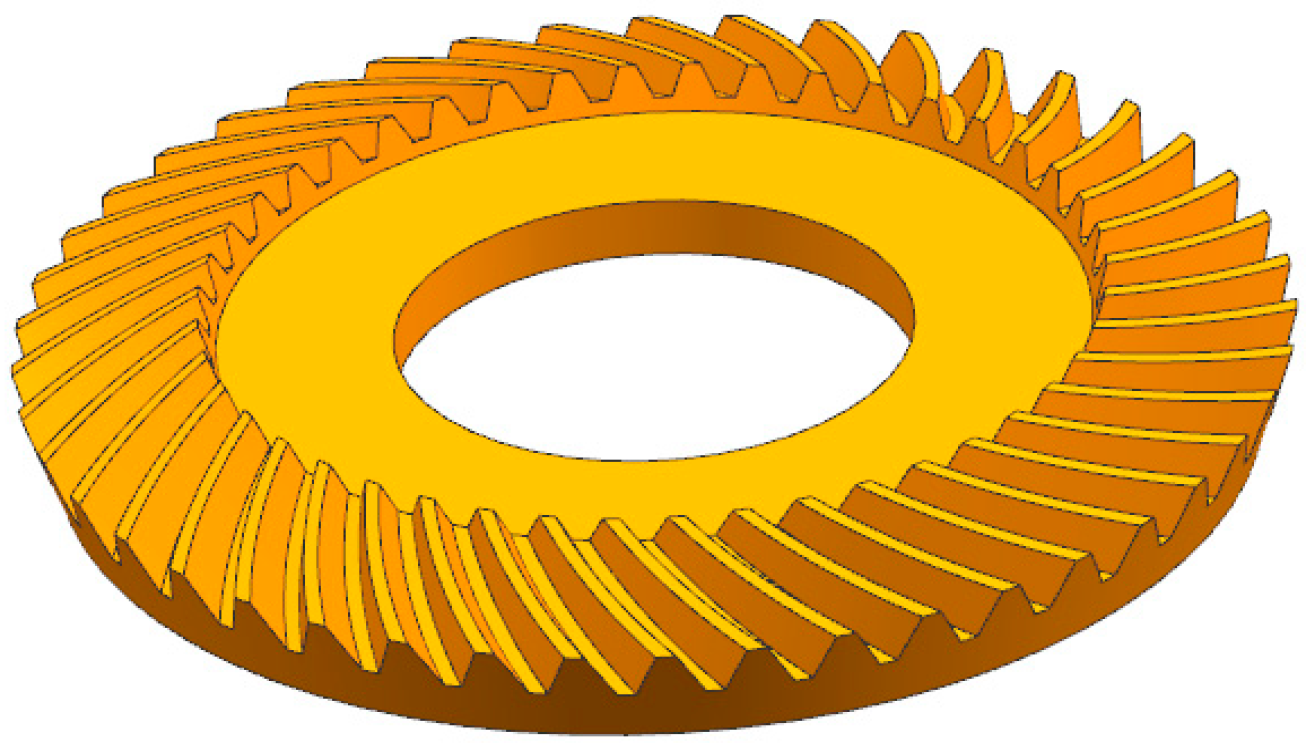
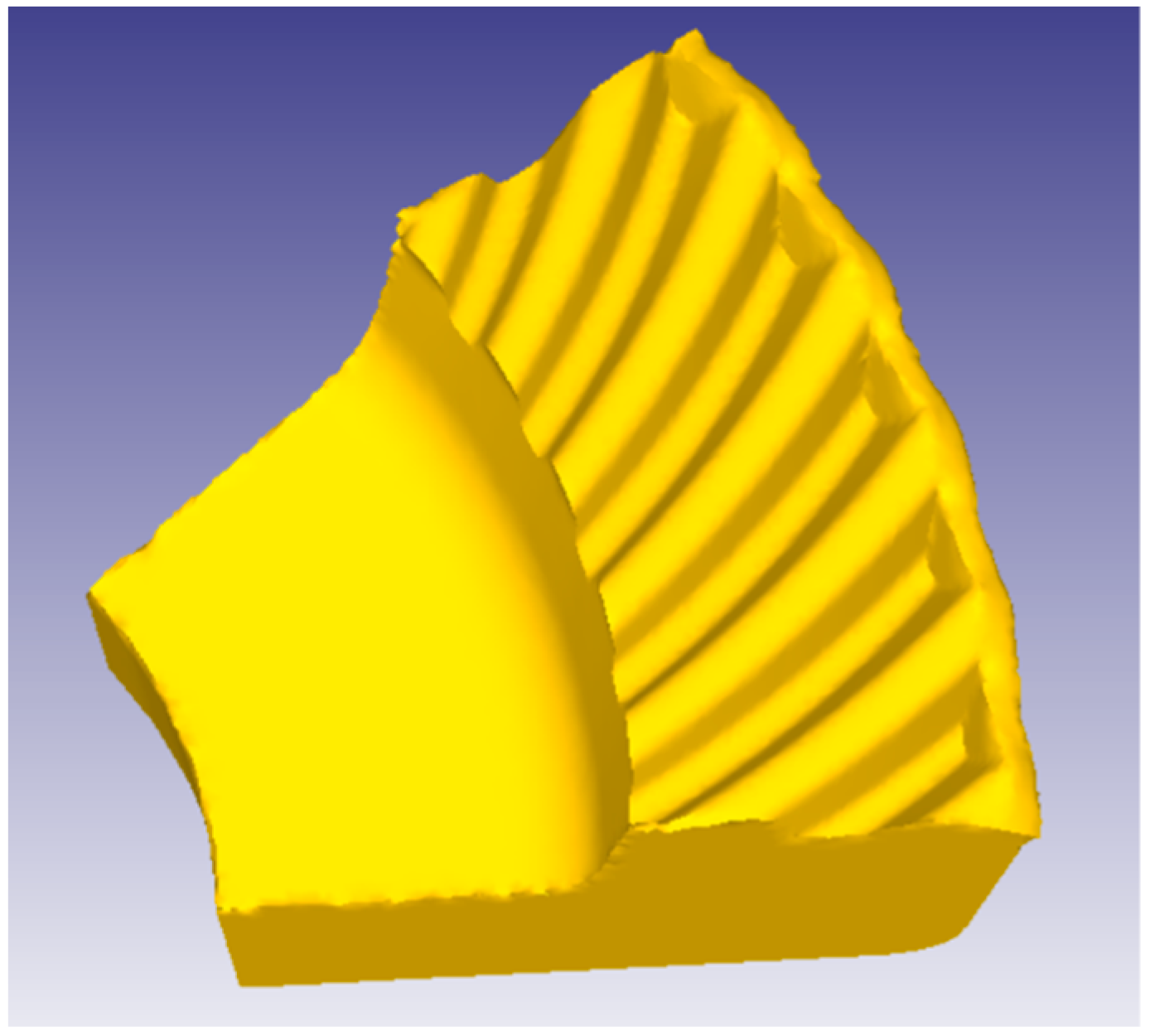
2.1. Three-Dimensional Modeling of Spiral Bevel Gear

With the progress and continuous development of computer simulation technology and numerical control machining technology, based on the meshing theory and local synthesis method of spiral bevel gear, according to the geometric parameters shown in Table 1, the coordinates of the points on the tooth surface are calculated, and the three-dimensional accurate modeling of spiral bevel gear is carried out by using NX 10.0 software on the computer [24], as shown in Figure 1.
The geometrical parameters of the spiral bevel gear in this paper are shown in Table 1.

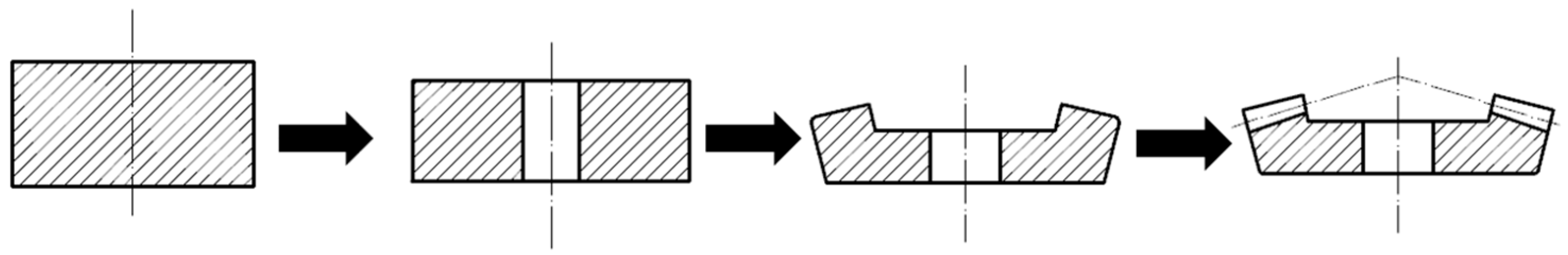
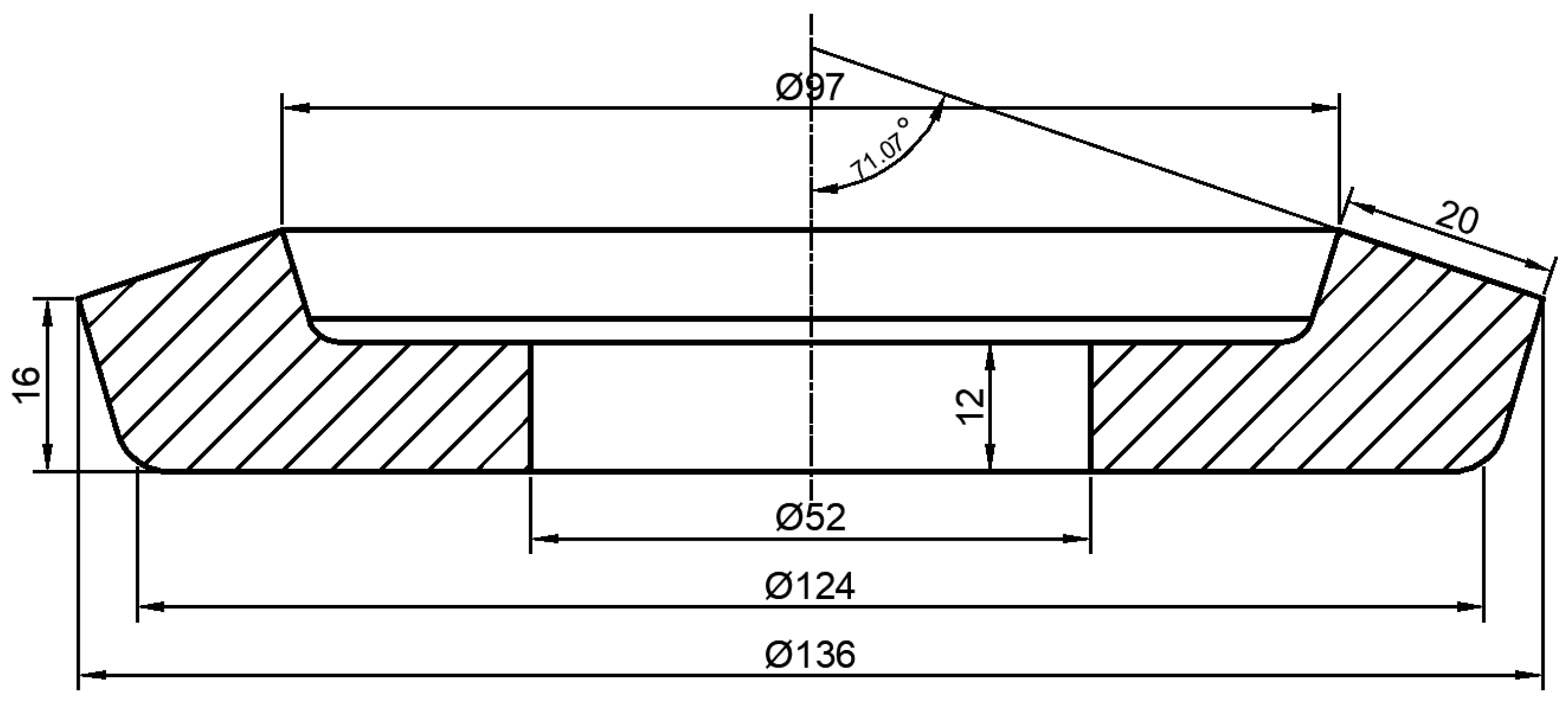
2.2. Design of Forging Gear Blank for Spiral Bevel Gear

Forging–finishing is a common metal forging process which is often used to manufacture hubs, gears and other similar parts. According to the requirements of the geometric parameters of the forging target spiral bevel gear, it is necessary to preprocess the gear blank. In the forging process, considering that the forging process of the spiral bevel gear belongs to unsteady large deformation, it is necessary to use a two-step forming process to forge the bar-shaped material into a blank with a gear ring. In this paper, the warm forging and finishing of the spiral bevel gear adopts the semi-closed forging process with one fire and two forgings, as shown in Figure 2. The forming process of the spiral bevel gear includes upsetting, punching, rolling preforming and final forging.
In terms of material selection, spiral bevel gears are usually made of high-strength alloy steel or carbon steel, and AISI-1045 is selected as the material in this experiment. The material has good cold and hot workability and is suitable for forging–forming. Its comprehensive mechanical properties are excellent, and it is widely used in the manufacturing of gear, bearings and other parts. According to the design principle that the diameter of the blank is equal to the diameter of the middle point of the tooth profile of the spiral bevel gear and the condition that the volume is unchanged before and after forging, the bar material of Φ 110 × 25 mm is selected as the specification of the gear blank.
In the design process of the gear blank, it is necessary to consider the various geometric parameters of the gear blank, including the pitch circle diameter, outer cone distance, etc. The setting of these parameters needs to be combined with factors such as the gear ratio, torque and strength [1]. At the same time, it should be noted that the inclination angle of the tooth root is very important for the manufacturing and strength of the gear blank, and it needs to be designed reasonably. The gear blank designed by CAD is shown in Figure 3, and the three-dimensional model of it is established by NX software, as shown in Figure 4.

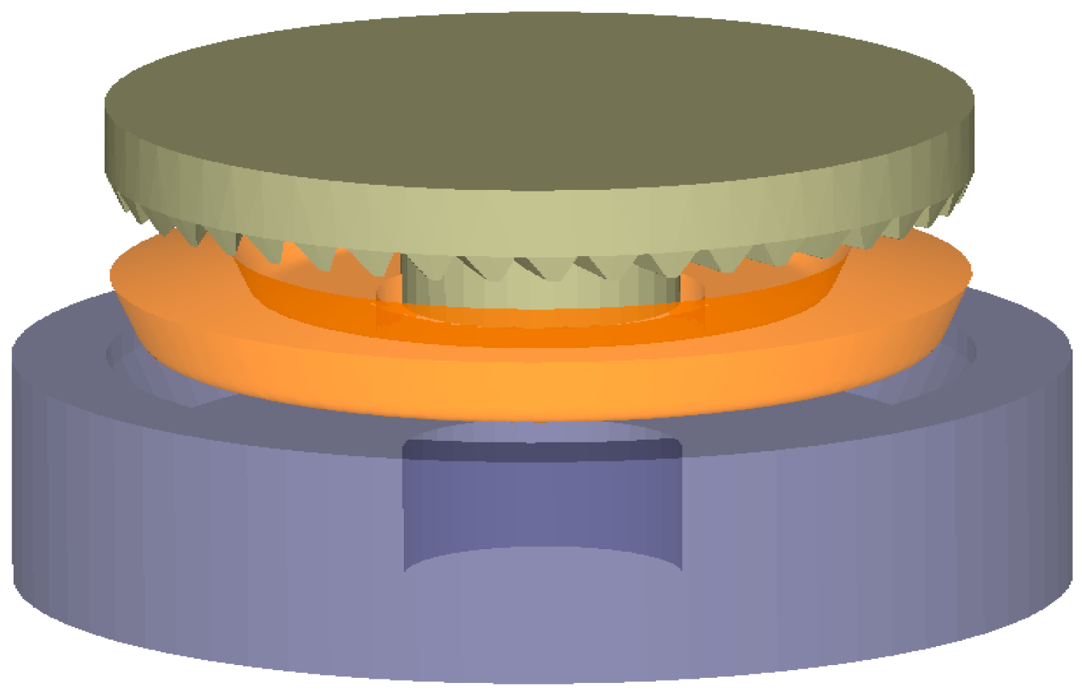
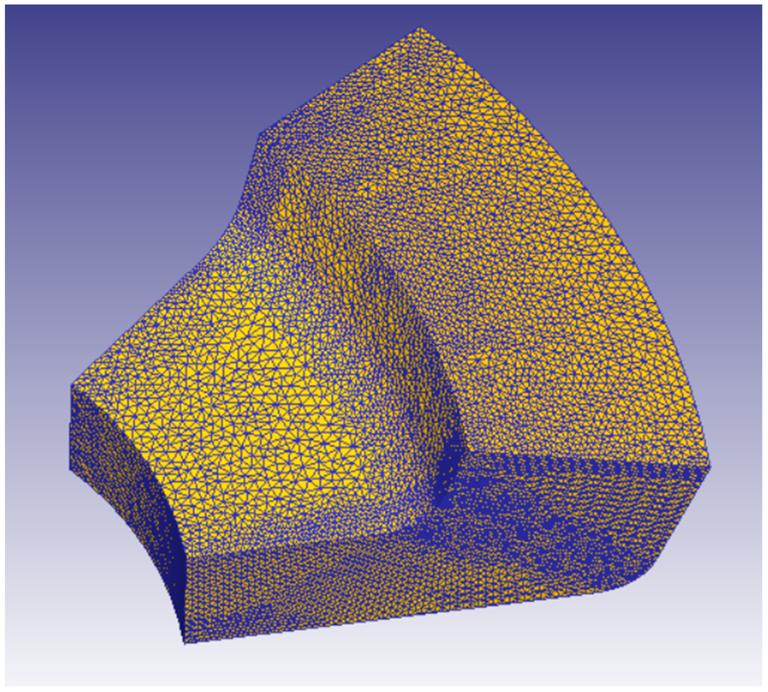
2.3. Establishment of Geometric Model for Numerical Simulation

According to the established model of spiral bevel gear, using the difference function of NX software, and in accordance with the requirements of die design process, the model of spiral bevel gear warm-forging gear die is established. Save the established wheel blank and die models in STL file format in NX software, and then import them into DEFORM-3D software for the finite element analysis. The geometric modeling is as shown in Figure 5.

2.4. Numerical Simulation Process Analysis and Scheme Formulation of Warm Forging–Finishing

The main process parameters affecting the forming quality of spiral bevel gear forging are the forging striking speed, die preheating temperature, friction factor and workpiece heating temperature. According to the principle of the single variable, three different groups of forging striking speed, die preheating temperature, friction factor and workpiece heating temperature were set, and the differences of numerical simulation results under different combinations of process parameters were studied and analyzed, so as to find out the influence law of various process parameters on the forging–forming quality of spiral bevel gears. The reasonable combination of process parameters is determined to guide the warm forging of spiral bevel gears, providing theoretical support for the warm-forging precision-forming process of spiral bevel gears.
Combined with the practical production experience, a reasonable range of process parameter values was selected to better analyze the influence law of the parameter in the warm-forging process of spiral bevel gear. According to the relevant data, the temperature of warm forging of 45 steel is 923~1073 K, and the heating temperatures of workpieces are 923 K, 1023 K and 1073 K, respectively. The forging striking speed of the die-forging hydraulic press is generally 1-to-50 mm/s, and the forging striking speeds are 10 mm/s, 20 mm/s and 30 mm/s, respectively. Considering the heat transfer performance between the blank and the die, the preheating temperature range of the warm-forging–finishing die is usually 423~573 K, so the preheating temperature of the die is 473 K, 523 K and 573 K, respectively. Lubricant materials in warm-forging–finishing are graphite, MoS2, PbO, etc., and the friction coefficient is 0.008~0.2, so the friction factors are selected to be 0.1, 0.15 and 0.2, respectively.
The numerical simulation process scheme formulated in this paper is shown in Table 2.
At the same time, the specific process parameter combinations of 12 kinds of process schemes used in the numerical simulation were determined. In addition, the forging die used in the simulation experiment in this paper adopts the semi-closed forging die structure, and the forging simulation geometry is shown in Figure 5. Due to the influence of the gear mold structure, the forging flying edge of the finished gear is distributed in the direction of the gear back cone, as shown in Figure 6.

3. Numerical Simulation of Warm Forging–Finishing of Spiral Bevel Gear

3.1. Numerical Simulation Parameter Settings

With the rapid development of computer graphics, applied mathematics and modern mechanics, the finite element method (FEM) has become a recognized and effective numerical computation method which can be used to deal with the problems of continuum mechanics and structural science. The rigid–plastic finite element method, rigid–viscoplastic finite element method and elastic–plastic finite element method are the most commonly used methods for finite element numerical simulation of metal plastic forming. The rigid–plastic finite element method is used in this paper.
DEFORM-3D software is a finite element simulation analysis system based on process simulation. The software has good stability, a simple operation and powerful functions. It can analyze the metal flow process and various parameters in the metal during the plastic deformation process and has been widely used in the field of forging–forming of complex parts.
In the forging process, the metal material not only bears the deformation force but also has heat transfer and heat exchange with the surrounding environment, leading to a non-constant temperature environment in the deformation process of the metal material. Therefore, the effect of heat transfer should be taken into account in the numerical simulation of the forging process of spiral bevel gears. Due to the complex forming process of warm-forging spiral bevel gear, many factors should be considered in the modeling of warm-forging spiral bevel gear in DEFORM-3D software, including the forging temperature of the gear blank, the limitation of the model boundary conditions and the influence of the heat produced in the process of forging deformation. In order to ensure the accuracy and efficiency of the simulation, the finite element simulation of the warm-forging–finishing spiral bevel gear is simplified as follows:
(1) In the process of warm-forging–finishing deformation of spiral bevel gear, the main deformation of the gear blank is plastic deformation, while the elastic deformation of the die and the workpiece is small, so the gear blank is set as a plastic body, and the die is set as a rigid body. In this experiment, the gear blank material is AISI-1045 [70–2000 F (293–1373 K)], and the die material is AISI-H-13.
(2) The warm-forging–finishing model of spiral bevel gear is shown in Figure 5. In order to improve the efficiency and accuracy of the simulation and shorten the operation time, 1/9 of the preform is taken for numerical simulation, the tetrahedral mesh is used to divide the preform, the number of generated meshes is set to about 120,000 and the automatic mesh division is set, as shown in Figure 7.
(3) In addition to the preheated temperatures of the die and forging, the heat loss of the gear blank and the heat exchange between the forging die during the forging process should also be taken into account. In order to make the simulation results more in line with the reality, the heat transfer option of the simulation model is turned on, the ambient temperature is set to 20 °C, the contact heat coefficient is set to 5 N/s/mm/C and the convection coefficient is set to 0.02 N/s/mm/C.

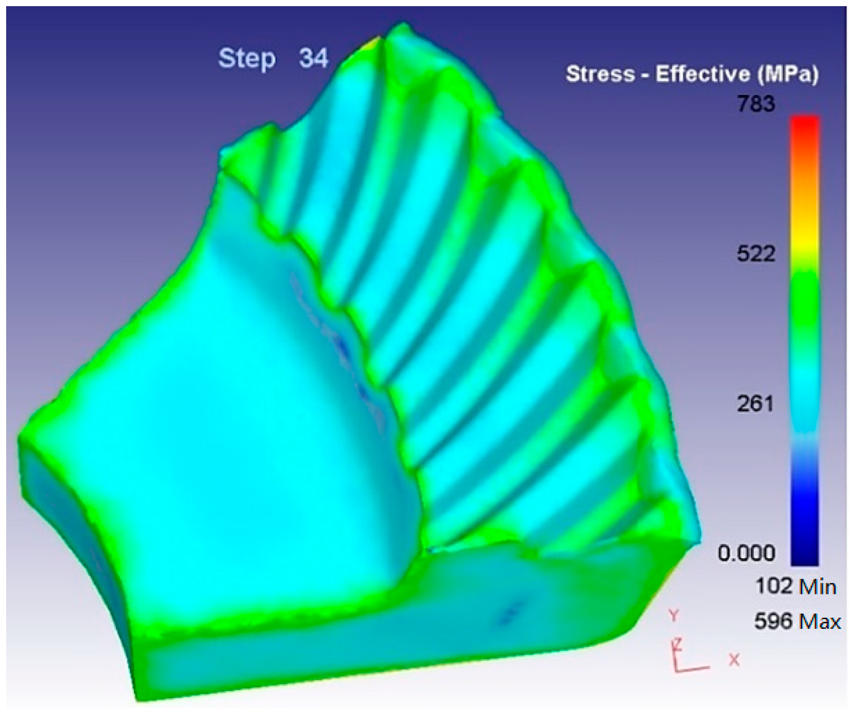
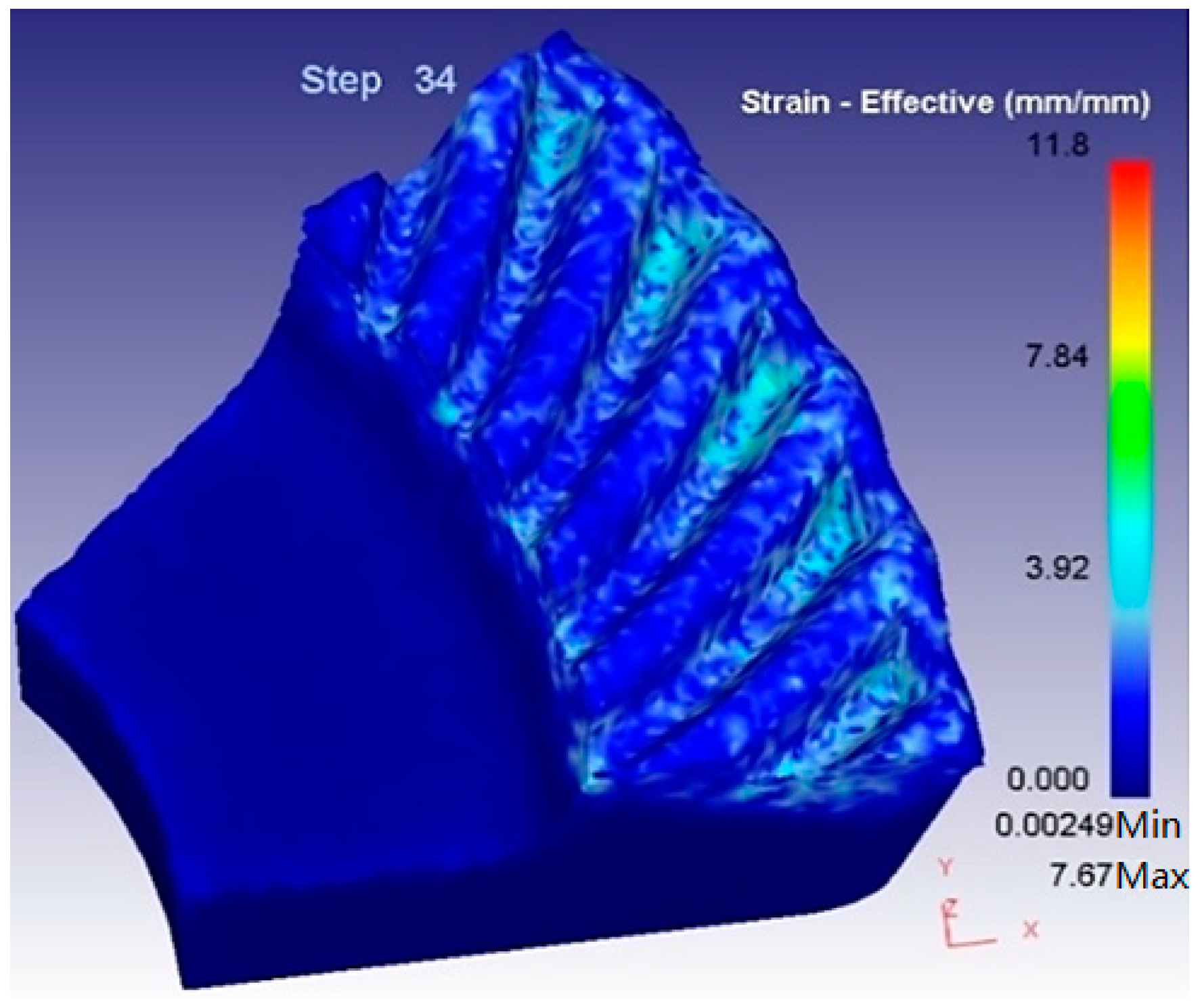
3.2. Brief Analysis on the Forging Process of Spiral Bevel Gear

During the forging process of the workpiece, the metal material flows due to the forging impact force. When the pre-divided mesh is distorted, the mesh’s remeshing setting in DEFORM-3D software will be activated, and the mesh will be automatically remeshed according to the preset mesh size and mesh ratio. The forging process of the spiral bevel gear is also the process of tooth filling completely, and the forming load of the workpiece and die will change in the process. In the plastic deformation process of the spiral bevel gear, the generated flash will be distributed along the back cone direction, so the effective stress and effective strain at the large end of the gear are relatively large, as shown in Figure 8 and Figure 9.
In order to analyze the plastic deformation process of the gear blank more specifically and accurately, eight points, including the tooth top and tooth space positions, are selected at the large end, middle part and small end of the gear forging. The position of the point is taken at the position of the transition arc of the gear tooth, as shown in Figure 10. By analyzing the effective strain and effective stress of these special points, the influence law of the main process parameters on the plastic forming quality of spiral bevel gear can be analyzed. Therefore, by changing the main process parameters in the forging process, the forming law of each group of spiral bevel gears can be analyzed, which can provide a theoretical basis for actual production.

3.3. Simulation and Result Analysis of Warm-Forging–Finishing of Spiral Bevel

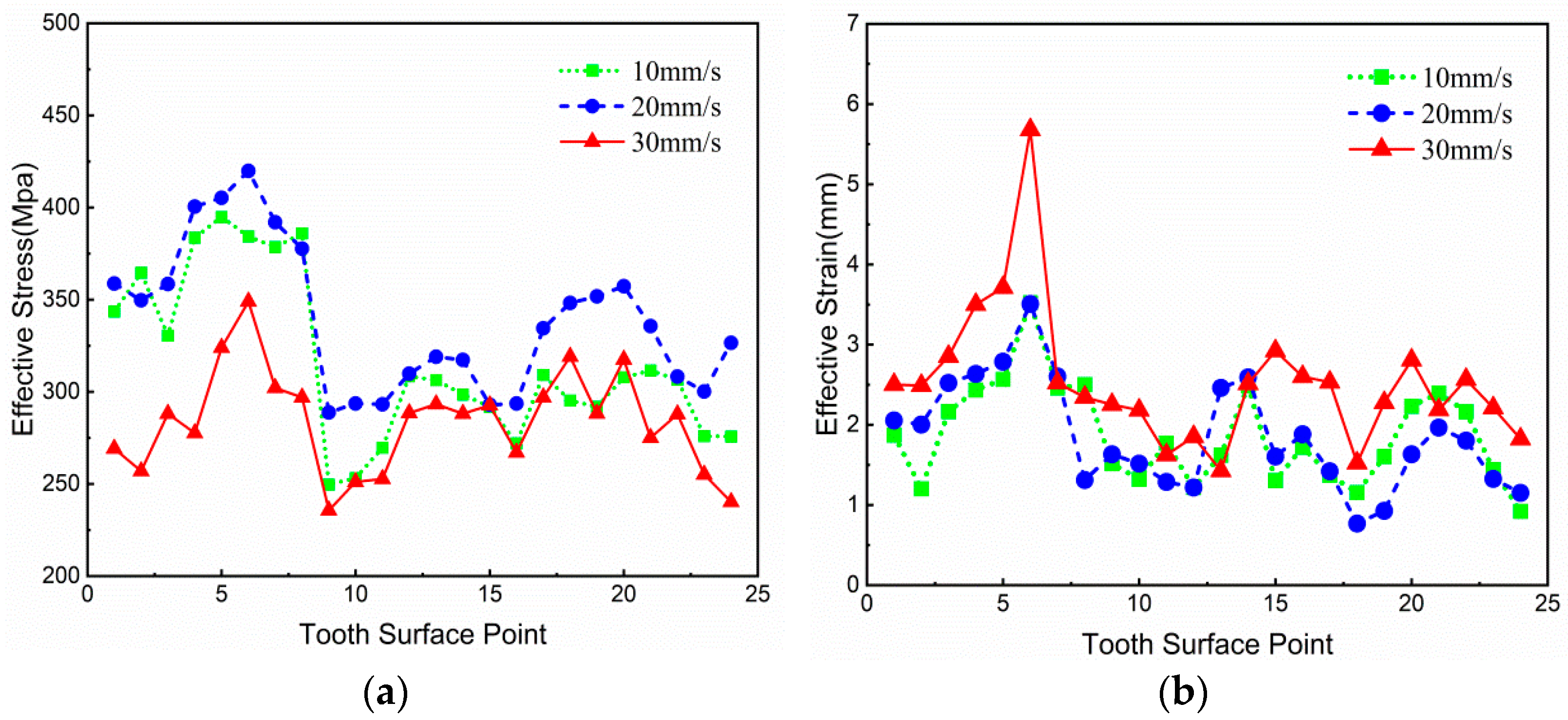
3.3.1. Influence of Forging Striking Speed on Forging Formation

Under the condition of not changing other process parameters, three different forging striking speeds, namely 10 mm/s, 20 mm/s and 30 mm/s, were selected to analyze the effective strain and effective stress at each reference point of the forging workpiece, and the variation curve is shown in Figure 11.
From Figure 11, it can be seen that, from the overall trend of the curve, the faster the forging striking speed is, the greater the effective strain at the reference point is and the smaller the effective stress is. Seen from the point of view of the gear as a whole, the effective strain and the effective stress of the large end of the spiral bevel gear are obviously larger than those of the middle and the small end of the gear, which is due to the formation of flash at the large end of the gear, so the deformation of the metal material at this part is larger. Because of the existence of the forging flash, the flow of metal material here requires a greater forging impact force, so the force at the root of the tooth is larger than that at other parts. From all parts of the gear, the effective stress and effective strain at the tooth top of the spiral bevel gear forging are greater than those at the tooth root. It should be noted that when the forging speed is set at 30 mm/s, the effective strain and effective stress at the tooth top of the forging have a large mutation.
In a word, the higher the forging striking speed is, the smaller the effective force the forging bears in the forging process and the faster the deformation speed is, which is conducive to the full deformation of the forging and can also improve the stress situation of the forging die. Therefore, a relatively higher forging blow speed can be selected in the actual production.

3.3.2. Influence of Die Preheating Temperature on Forging–Forming

Three different die preheating temperature conditions—473 K, 523 K and 573 K—were selected to analyze the effective strain and effective stress at each reference point of the forging workpiece, and the simulation results are shown in Figure 12.
It can be seen from Figure 12 that, from the overall trend of the curve, the higher the die preheating temperature is, the greater the effective strain at the reference point of the forging is, which indicates that the increase in the die temperature is conducive to the flow deformation of the material and the filling of the gear tooth material. From the whole gear, the effective stress is gradually reduced along the gear from the big end to the small end, but with the increase in the die preheating temperature, the effective stress is not significantly reduced; on the contrary, when the die preheating temperature is 573 K, the effective stress is higher than that when the die preheating temperature is 523 K. Therefore, the preheating temperature of the warm-forging die for spiral bevel gears should be selected in the range of 473 K~523 K, which can not only ensure the forming quality of forged gears but can also help to reduce the stress of the die in the forging process and improve the service life of the die.

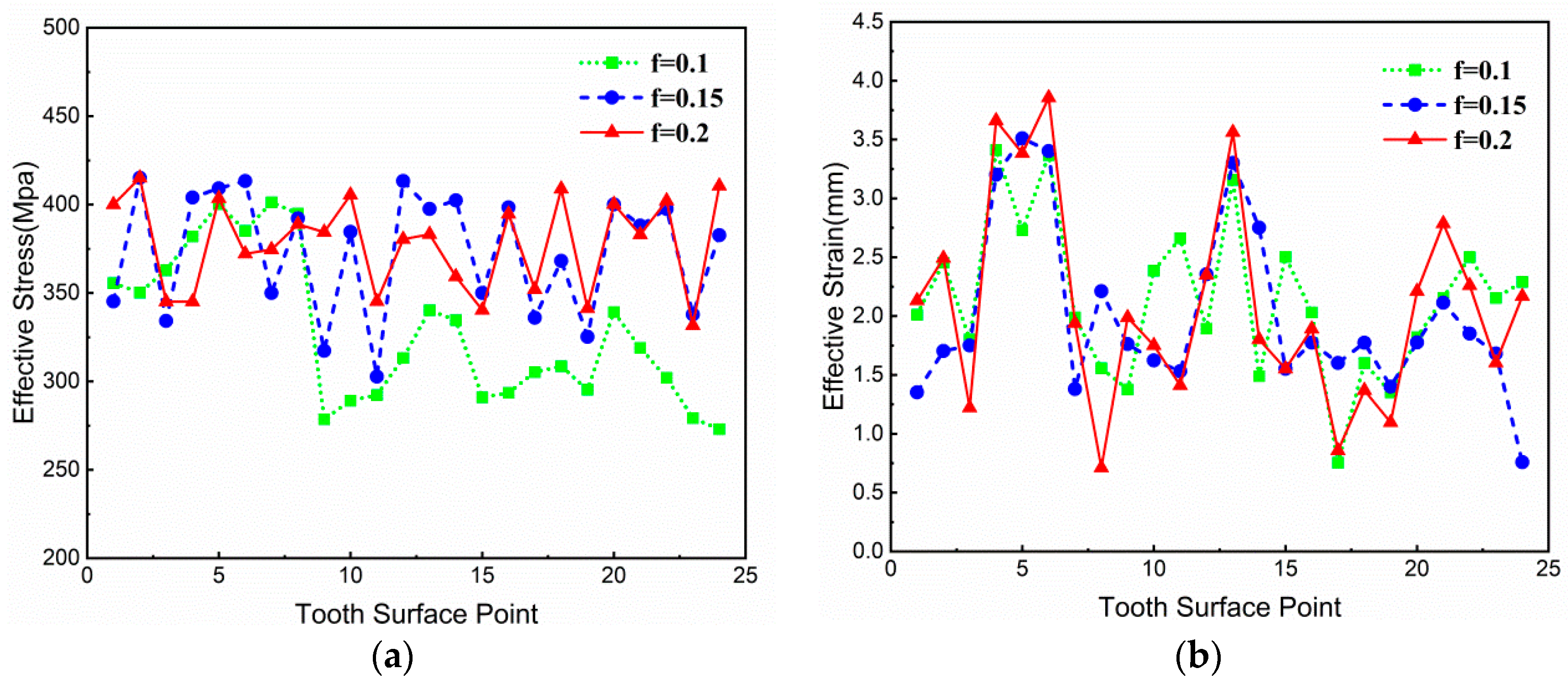
3.3.3. Influence of Friction Factor on Forging–Forming

Three different friction factors, namely 0.1, 0.15 and 0.2, were selected to analyze the effective strain and effective force at each reference point location of the forged workpiece, and the value variation curve is shown in Figure 13.
We can see from the overall trend of the curve, the larger the friction factor is, the larger the effective stress value of the forging is. This is because the friction conditions in the forging process have a great impact on the quality of forging–forming; bad lubrication conditions will cause the material flow rate in contact with the die to be slow, the forging force will increase and other phenomena will occur. The different friction factors of the conditions of the effective strain value of gears at various places do not have much of an impact. From the gear as a whole, the effective stress value and effective strain value from the gear’s large end to the middle of the gear and the small end of the gear is decreasing in order, which is due to the large end of the gear forging when there is a flying edge, increasing the deformation and stress value. From all parts of the gear, the effective stress and strain force at the root of the forged gear tooth are larger than those at the tooth top and tooth surface, and the effective stress and strain value at the tooth top are the smallest.
Therefore, good lubrication conditions can ensure the filling quality of the tooth profile in the forging process of spiral bevel gears, reduce the forming load of forgings and forging dies, improve the stress concentration phenomenon at the big end of gears and the top of gear teeth and thus improve the service life of dies.

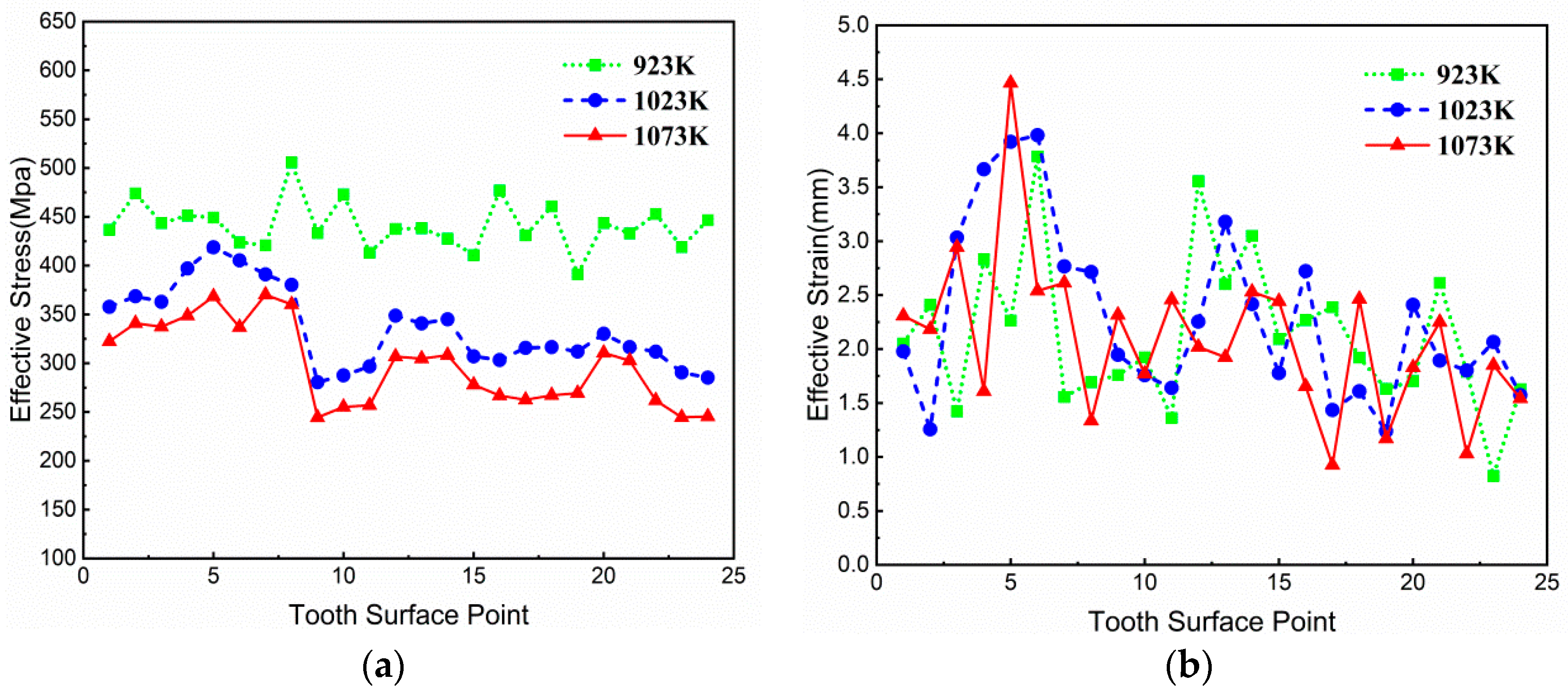
3.3.4. Influence of Workpiece Heating Temperature on Forging–Forming

The heating temperature of the workpiece was selected to be 923 K, 1023 K and 1073 K, respectively; the effective stress and strain at each reference point positions of the forged workpiece were analyzed, and the simulation results are shown in Figure 14.
As can be seen from Figure 14, from the overall trend of the curve, it can be clearly observed that the higher the heating temperature of the workpiece, the smaller the effective stress value of the forging. The reason is that the higher the temperature of the workpiece, the stronger the fluidity of the material and the lower the deformation resistance. From the whole gear, the effective strain and effective stress of the big end of the gear are significantly greater than those of the middle and small end of the gear, which is mainly caused by the flash of the forging. From the various parts of the gear, the effective strain at the reference point of the tooth root of the forging is significantly greater than that at the reference point of the tooth surface and the tooth top, which is due to the fact that the forging flash is produced by the flow of excess metal material from the tooth root along the direction of the back cone of the gear.
Therefore, the increase in the forging temperature of the workpiece can effectively reduce the stress generated during the forging of the spiral bevel gear, especially the equivalent stress at the tooth root of the big end, so as to improve the stress condition at the tooth top of the big end of the forging die and reduce the probability of fracture failure of the tooth top of the tooth die.
By using DEFORM-3D software, the changes in four process parameters, namely forging speed, die preheating temperature, friction factor and workpiece heating temperature, in the warm-forging process of spiral bevel gears are simulated and analyzed, and the changing laws of the metal material flow and forming load in the warm-forging process of spiral bevel gears are obtained. The forging–forming load will affect the precision of the forging gear, die life, forging equipment, etc. Reducing the forming force can reduce costs and improve quality, which is of great significance for actual production. Therefore, it is necessary to further optimize the warm forging-process parameters of spiral bevel gear to obtain higher-quality parts.

4. Optimization of Warm-Forging–Finishing Process Parameters of Spiral Bevel Gear

4.1. Identification of Evaluation Indicators

The forging–forming load has a significant impact on the quality of the forged gear and the service life of the gear die. If the forming load is large in the gear forging process, it will result in the following effects on the finished gear and the gear die:
(1)
The geometric accuracy of the finished gear will be affected. If the forming force is too large, the metal blank will produce unnecessary elastic deformation; and if the deformation is too large, it will result in a large tooth profile error, tooth alignment error and so on, which will reduce the geometric accuracy of the finished forging.
(2)
The service life of the tooth mold will be reduced. Higher forming forces acting on the die during the forging process may cause premature fatigue damage to the surface of the die, thus affecting its service life.
(3)
The surface quality of the finished gear can also be affected. Because the forming force is too large, it may cause cracks in the gear, especially in the stress concentration areas, such as the root and top of the gear teeth, thus affecting its surface quality.
Therefore, reducing the forming forces in the gear forging process can improve the geometric accuracy of the finished gear, the durability of the tooth die and the surface quality of the gear, which is very important for the forming quality of the spiral bevel gear and the service life of the die.
In this paper, the forming load of the upper die is used as the evaluation index to optimize the forging process parameters. In order to reduce the number of simulation experiments, the orthogonal experiment method was used to optimize the four process parameters in the warm-forging–finishing process of spiral bevel gear [25], including the forging speed, the die preheating temperature, the friction factor between the die and the wheel blank, and the workpiece heating temperature. And the influence of the technological parameters on the forming force of the spiral bevel gear in the process of warm forging is analyzed. Finally, a set of optimal combinations of process parameters is selected for controlling the forming force in the warm-forging–finishing under the premise of ensuring the forming quality of the spiral bevel gear.

4.2. Orthogonal Experimental Design

In this experiment, there are four influencing factors, namely the forging striking speed (A), die preheating temperature (B), friction factor (C) and workpiece heating temperature (D). Without considering the influence of the interaction among the factors, we can establish that there are three levels for each factor. Table 3 shows the experimental factors and levels.
It can be seen from the above table that this orthogonal experiment is a three-level four-factor experiment, so the orthogonal experiment table of L9 (34) is used, as shown in Table 4. There are nine different combinations of process parameters in this orthogonal experimental table. In this paper, the forming force of the upper tooth die in the forging process is taken as the measurement index, and the numerical simulation of the warm-forging spiral bevel gear is carried out for these nine combinations.

4.3. Data Analysis and Results of Orthogonal Experiment

The simulation experiment is carried out according to the level combinations formulated in the previous orthogonal table. There are nine groups in this experiment. The experimental results are given in the last column of Table 5.
The experiment results and data analysis are shown in Table 5. R is used to represent the range at the level i (i = 1, 2, 3). The degree of influence of the parameter on the forging–forming load can be seen from the size of the range, R. The larger the range (R) is, the greater the influence of the parameter on the forming force is, and the parameter is the main influence factor. The smaller the range (R) is, the smaller the influence of the parameter on the forming force is, and the parameter is the secondary influence factor. According to the value of the range, R, in Table 5, it can be seen that the influence of each process parameter on the forging–forming force is D, C, B and A, from the largest to the smallest.
In Table 5, Ki represents the sum of the experimental results corresponding to a factor at level i (i = 1, 2 or 3 in this experiment). The smaller the Ki value is, the smaller the forming load is, indicating that the factor performs better at this level. For example, the value of K3 in factor A is the smallest, indicating that the performance is the best when the forging striking speed is 30 mm/s. Similarly, the values of K2 in factor B, K1 in factor C and K3 in factor D are the smallest. Therefore, the optimal combination of process parameters should be A3B2C1D3, which is the No. 8 experimental scheme, A3B2C1D3, with the minimum forging–forming force.
In Table 5, ki represents the arithmetic mean of the experimental results obtained when the factor level on any column is taken as i; that is, ki = Ki/s, where s is the number of occurrences of the previous level on any column. Here, we take the factor level as the abscissa and ki as the ordinate and draw the relationship diagram between all factors and experimental indicators, creating a trend diagram, as shown in Figure 15. It can be more clearly observed from the figure that the optimal experimental scheme is still A3B2C1D3.
Therefore, the optimal combination of process parameters in this experiment is shown in Table 6.

5. Conclusions

In this study, DEFORM-3D software was used to establish the simulation model of the warm forging of the spiral bevel gear, and the numerical simulation of a warm-forging–finishing process of spiral bevel gear was carried out. The main conclusions are as follows:
(1)
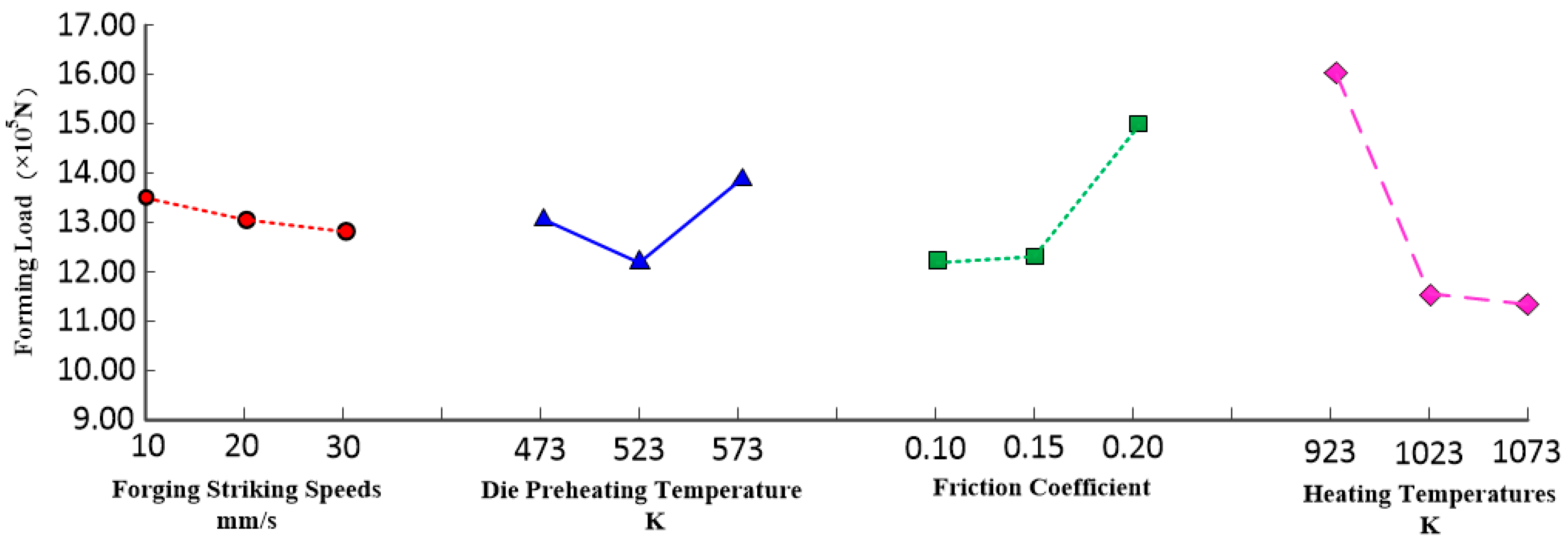
In the warm-forging process of spiral bevel gear, the maximum deforming force is at the dedendum of the gear big end, and the deforming force increases with the increase in the friction factor in the forging process and decreases with the increase in the forging speed and workpiece heating temperature.
(2)
Based on the orthogonal experiment method, the combination of four process parameters was designed, and the combination of process parameters with the minimum warm-forging force of spiral bevel gear was obtained as follows: a forging speed of 30 mm/s, a die preheating temperature of 523 K, the friction factor of 0.1, and a workpiece heating temperature of 1073 K.
(3)
The combination of a numerical simulation and orthogonal test can help to work out the warm-forging process scheme of spiral bevel gear quickly, accurately and reasonably.

Author Contributions

Conceptualization, Z.W. and C.J.; methodology, Z.W.; software, Z.W.; validation, B.W., Y.W. and C.J.; formal analysis, Y.W.; investigation, Z.W.; resources, C.J.; data curation, Z.W.; writing—original draft preparation, Z.W.; writing—review and editing, Z.W. and C.J.; visualization, Y.W.; supervision, B.W.; project administration, B.W.; funding acquisition, C.J. and B.W. All authors have read and agreed to the published version of the manuscript.

Funding

This research was funded by National Key Project (J2019-VII-0017-0159).

Institutional Review Board Statement

Not applicable.

Informed Consent Statement

Not applicable.

Data Availability Statement

The data presented in this study are available on request from the corresponding author. The data are not publicly available due to the requirements of the project party.

Acknowledgments

The authors would like to thank all the authors of the references that gave us inspiration and help. The authors are grateful to the editors and anonymous reviewers for their valuable comments that improved the quality of this paper.

Conflicts of Interest

The authors declare no conflict of interest.

References

  1. Zheng, J.S.; Li, J.H. Near-net-shape forming technology and manufacturing process of precision die forging for spiral bevel gears. J. Mech. Transm. 2009, 33, 111–112. [Google Scholar]
  2. Zhao, J.; Luo, S.M.; Li, F.Q. Study on precision forming and lift-out process of small cone angle spiral bevel gear by finite element analysis. Int. J. Adv. Manuf. Technol. 2017, 92, 2559–2568. [Google Scholar] [CrossRef]
  3. Zhang, M.; Huang, S.Y.; Zhao, Y.M.; Wang, H.J.; Zhang, S.H. Deformation characteristics of bevel pinion of automotive output shaft by no-flash die forging. Chin. J. Nonferrous Met. 1999, 3, 567–572. [Google Scholar]
  4. Douglas, R.; Kuhlmann, D. Guidelines for precision hot forging with applications. J. Mater. Process. Technol. 2000, 98, 182–188. [Google Scholar] [CrossRef]
  5. Feng, W.H.; Duan, H.J.; Chen, Y.Y.; Zhang, W.Q. Research on precision forming process parameters of spiral bevel gear based on numerical simulation. Forg. Stamp. Technol. 2014, 39, 147–150. [Google Scholar]
  6. Luo, S.M.; Fang, Y. Numerical simulation of precision forging process of spiral bevel gears. China Mech. Eng. 2009, 20, 485–487. [Google Scholar]
  7. Zhang, H.; Chen, J.F.; Yang, J.J.; Li, T.X. Analysis of precision forging process of spiral bevel gears. Mach. Tools Hydraul. 2018, 46, 97–103. [Google Scholar]
  8. Gao, Z.S.; Li, J.B.; Deng, X.Z.; Yang, J.J.; Chen, F.X.; Xu, A.J.; Li, L. Research on gear tooth forming control in the closed die hot forging of spiral bevel gear. Int. J. Adv. Manuf. Technol. 2018, 94, 2993–3004. [Google Scholar] [CrossRef]
  9. Knust, J.; Stonis, M.; Behrens, B.-A. Preform optimization for hot forging processes using an adaptive amount of flash based on the cross section shape complexity. Prod. Eng. 2016, 10, 587–598. [Google Scholar] [CrossRef]
  10. Chen, F.X.; Huang, T.; Guo, J.Q.; Yan, X.J. The study of physical simulation and numerical simulation for precision forming of spiral bevel driven gear. Manuf. Technol. Mach. Tool 2010, 5, 36–39. [Google Scholar]
  11. Cai, Y.Y.; Zhou, Z.X.; Wang, W. Influence of process parameters on precision forging process of spiral bevel gear. Equip. Manuf. Technol. 2020, 8, 31–34. [Google Scholar]
  12. Xu, W.; Wan, Y.; Sha, X.M. Influence of mold loading mode on closed forging process for transmission spiral bevel gear. Forg. Stamp. Technol. 2022, 47, 75–80. [Google Scholar]
  13. Li, H.B.; Zhang, R.H.; Yu, H.; Yi, X.; OuYang, J.Z.; Cao, C.L. Experimental research on precision forming of driven spiral bevel gear preformed by enlarging die corner. J. Plast. Eng. 2021, 28, 36–41. [Google Scholar]
  14. Li, T.X.; Zhang, X.L.; Fu, J.Z.; Gao, Z.S.; Wu, S.B.; Yang, C. Influence of the technological parameter and die structure on metal flow line for precision forging car gear blank. J. Mech. Transm. 2015, 39, 154–157. [Google Scholar]
  15. Zhao, Z.; Bai, X.J.; Hu, C.L. Status and development trend of precision forging technology. Forg. Stamp. Technol. 2018, 43, 90–95. [Google Scholar]
  16. Luo, J.; Yin, X.Y. Application of precision warm forging technology in auto parts. Die Mould. Technol. 2018, 4, 32–36. [Google Scholar]
  17. Raghu, K.; Balachandran, G.; Ravichandar, D. Microstructure and mechanical properties in warm forged 27MnSiVS6 micro-alloyed steel. Trans. Indian Inst. Met. 2019, 72, 411–421. [Google Scholar] [CrossRef]
  18. Skubisz, P.; Lisiecki, Ł. Warm-Forging Characteristics and Microstructural Response of Medium-Carbon High-Strength Steels for High-Duty Components. Key Eng. Mater. 2014, 611, 167–172. [Google Scholar] [CrossRef]
  19. Zheng, M.Y.; Xie, J.S.; Chen, W.L.; Liu, D.; Tang, T.; Wang, S.Y. Process parameters optimization for spur gear warm forging. J. Netshape Form. Eng. 2012, 4, 14–18. [Google Scholar]
  20. Yang, T.S.; Deng, J.Y.; Chang, J. Study on intnal helical gear worm forging by finite element analysis. Appl. Mech. Mater. 2014, 465, 1361–1364. [Google Scholar] [CrossRef]
  21. Zhang, Z.P. Optimum design of warm forging process and die for shaft gear based on ANSYS. Hot Work. Technol. 2018, 47, 177–183. [Google Scholar]
  22. Sun, Y.; Huang, S.T.; Wu, H.; Dai, X.D.; Cao, J.G. Research on warm forging process and defect control for combined gear based on numerical simulation. Die Mould. Ind. 2021, 47, 1–5. [Google Scholar]
  23. Sun, Z.L.; Li, Z.H.; You, S.; Sheng, N.; Zhang, M. Optimization analysis of numerical simulation of warm closed forging die structure for cylindrical gears. Hot Work. Technol. 2016, 45, 117–120. [Google Scholar]
  24. Liu, G.L.; Tian, Y.J.; Fan, H.W.; Wang, M.Y. Three dimensional modeling technology for spiral bevel gear based on Matlab and UG. Heavy Mach. 2011, 2, 6–9. [Google Scholar]
  25. Zhou, J.; Lin, L.; Luo, Y. The multi-objective optimization design of a new closed extrusion forging technology for a steering knuckle with long rod and fork. Int. J. Adv. Manuf. Technol. 2014, 72, 1219–1225. [Google Scholar] [CrossRef]
Figure 1. Three-dimensional modeling of spiral bevel gear.
Applsci 14 01147 g001
Figure 2. Forging process for spiral bevel gear blank.
Applsci 14 01147 g002
Figure 3. Two-dimensional design of forged wheel blanks for spiral bevel gear.
Applsci 14 01147 g003
Figure 4. Three-dimensional model of forged gear blank for spiral bevel gear.
Applsci 14 01147 g004
Figure 5. Numerical simulation geometric model of warm forging.
Applsci 14 01147 g005
Figure 6. Finished product of forging numerical simulation.
Applsci 14 01147 g006
Figure 7. Schematic diagram of gear blank meshing.
Applsci 14 01147 g007
Figure 8. Effective stress field quantities.
Applsci 14 01147 g008
Figure 9. Effective strain field quantities.
Applsci 14 01147 g009
Figure 10. Distribution of tooth reference points.
Applsci 14 01147 g010
Figure 11. Effective strain at the reference point of the final forgings of the spiral bevel gear with different forging striking speeds: (a) effective force and (b) effective strain.
Applsci 14 01147 g011
Figure 12. Effective strain at the reference point of the final forgings of the spiral bevel gear at different die preheating temperatures: (a) effective force and (b) effective strain.
Applsci 14 01147 g012
Figure 13. Effective strain and stress at the reference point of the final forgings of spiral bevel gear with different friction factors: (a) effective stress and (b) effective strain.
Applsci 14 01147 g013
Figure 14. Effective strain at the reference point of the final forgings of the spiral bevel gear at different workpiece heating temperatures: (a) effective stress and (b) effective strain.
Applsci 14 01147 g014
Figure 15. Trend diagram of influence of process parameters on gear forming load.
Applsci 14 01147 g015
Table 1. Geometrical parameters.
ParametersGear
Tooth number 44
Module (mm)3
Average pressure angle (°)20°
Midpoint helix angle (°)35°
Hand of helixLH
Diameter of indexing circle (mm)132
Tooth top height (mm)1.516
Tooth root height (mm)4.148
Matching gear teeth number15
Top cone angle (°)73°39′3″
Partial cone angle (°)71°10′31″
Root cone angle (°)67°0′14″
External taper distance (mm)69.73
Mounting distance (mm)27 ± 0.1
Table 2. The numerical simulation process scheme.
Experimental SchemeProcess Parameters
Forging Striking
Speeds (mm/s)
Die Preheating
Temperature (K)
Friction
Factor
Workpiece Heating
Temperature (K)
Scheme I205230.15923
1023
1073
Scheme II105230.151023
20
30
Scheme III204730.151023
523
573
Scheme IV205230.11023
0.15
0.2
Table 3. Table of factors and levels of the experiment.
Factor LevelFactors
A (mm/s)B (K)CD (K)
1104730.10923
2205230.151023
3305730.201073
Table 4. Table of orthogonal experiments.
Experiment No.A (mm/s)B (K)CD (K)Experimental Scheme
1104730.1923A1B1C1D1
2105230.151023A1B2C2D2
3105730.21073A1B3C3D3
4204730.151073A2B1C2D3
5205230.2923A2B2C3D1
6205730.11023A2B3C1D2
7304730.21023A3B1C3D2
8305230.11073A3B2C1D3
9305730.15923A3B3C2D1
Table 5. Experimental scheme and experimental results analysis table.
Experiment No.ABCDForming Load
(×105 N)
1111115.80
212229.94
3133314.80
4212310.30
5223117.40
6231211.50
7313213.20
832139.27
9332116.40
K140.5439.3036.5749.60
K239.2036.6136.6434.64
K338.4742.3045.4034.37
k113.5113.1012.1916.53
k213.0712.2012.2111.55
k312.8214.1015.1311.46
R2.075.698.8315.23
Primary → SecondaryDCBA
Table 6. Optimal process parameter combinations.
A (mm/s)B (K)CD (K)
305230.11073
Disclaimer/Publisher’s Note: The statements, opinions and data contained in all publications are solely those of the individual author(s) and contributor(s) and not of MDPI and/or the editor(s). MDPI and/or the editor(s) disclaim responsibility for any injury to people or property resulting from any ideas, methods, instructions or products referred to in the content.

