Abstract
As large-scale depletion of shallow coal seams and increasing mining depths intensify, the frequency and intensity of mining-induced earthquake events have significantly risen. Due to the complex formation mechanisms of high-energy mining-induced earthquakes, precise identification and early warning cannot be achieved with a single monitoring method, posing severe challenges to coal mine safety. Therefore, this study conducts an in-depth risk analysis of two high-energy mining-induced earthquake events at the 3308 working face of Yangcheng Coal Mine, integrating microseismic monitoring, stress monitoring, and seismic source mechanism analysis. The results show that, by combining microseismic monitoring, seismic source mechanism inversion, and dynamic stress analysis, critical disaster-inducing factors such as fault activation, high-stress concentration zones, and remnant coal pillars were successfully identified, further revealing the roles these factors play in triggering mining-induced earthquakes. Through multi-dimensional data integration, especially the effective detection of the microseismic “silent period” as a key precursor signal before high-energy mining-induced earthquake events, a critical basis for early warning is provided. Additionally, by analyzing the spatiotemporal distribution patterns of different risk factors, high-risk areas within the mining region were identified and delineated, laying a foundation for formulating precise prevention and control strategies. The findings of this study are of significant importance for mining-induced earthquake risk management, providing effective assurance for safe production in coal mines and other mining environments with high seismic risks. The proposed analysis methods and control strategies also offer valuable insights for seismic risk management in other mining industries, ensuring safe operations and minimizing potential losses.
1. Introduction
Mining-induced earthquake refers to the phenomenon of vibrations caused by the rapid release of elastic energy in rock masses, induced by disturbances from underground resource extraction. These events are common and will invariably occur with the exploitation of underground solid resources [1]. However, as mining depth increases, the scale of goaf areas expands, the complexity of mine structure intensifies, and the surrounding stress levels rise, the frequency and intensity of high-energy mining-induced earthquake events are increasing [2,3,4]. Frequent high-energy mining-induced earthquake activity typically indicates the gradual accumulation of stress within rock masses, which can further lead to rockburst hazards, posing significant threats to mine safety and regional social stability [5]. Consequently, research on precursor identification and control strategies for high-energy mining-induced earthquake event risks is crucial to ensure safe mining operations. To enhance the safety and efficiency of deep coal mining, various monitoring and early warning methods have been widely applied, including microseismic monitoring [6,7,8], electromagnetic radiation monitoring [9,10], stress monitoring [11,12], and infrared monitoring [13,14]. Additionally, in conditions of dynamic hazards, rock mass monitoring should be carried out in parallel with the selection of a support system capable of absorbing the largest possible amount of dynamic energy, ensuring the safety of mining operations by reducing the impact of dynamic events [15]. Domestic and international researchers have conducted in-depth studies on these monitoring techniques, continuously optimizing and integrating different methods, thereby establishing a solid technical foundation for the identification of high-energy mining-induced earthquake precursors and the development of effective risk control strategies.
Microseismic monitoring, as a real-time and efficient monitoring method, utilizes sensors installed at various locations underground in coal mines to capture seismic signals generated by the fracturing of coal and rock masses. This technique enables the localization of seismic sources and the calculation of event energy [16,17,18] and has been widely applied in coal mine operations. Zhang et al. [5], using a microseismic monitoring system, analyzed the response characteristics of different parameters prior to mining-induced earthquake events and defined a new prediction parameter—the Energy Rockburst Warning (ERW) index. Source mechanism inversion is a crucial technique in seismic analysis, as it uses raw waveform data collected from multiple sensors to precisely locate seismic sources, determine fracture modes, and calculate parameters such as moment magnitude and energy [19], offering valuable insights into seismic risk precursors and triggering factors. Song et al. [20] investigated the destruction mechanisms and stress evolution in irregular coal pillar anomaly zones using microseismic monitoring, moment tensor inversion, and velocity tomography. Similarly, He et al. [21] studied the outcomes of rockbursts, as well as the spatiotemporal evolution of microseismic (MS) and acoustic emission (AE) monitoring results. They analyzed the relationship between AE and MS precursor signals prior to rockbursts, finding that their spatiotemporal evolution patterns could serve as early warning indicators for rockbursts. Furthermore, the study also indicates that the “silent period” of mining-induced earthquakes is one of the critical precursor signals. In the hours to days leading up to a mining-induced earthquake, the frequency and energy of microseismic events often show a significant reduction or even a temporary cessation, a phenomenon referred to as the “silent period” [22,23]. The identification of the silent period is crucial for predicting mining-induced earthquakes, as its presence often indicates high-risk areas for such events. Although microseismic monitoring provides high real-time accuracy in locating the seismic source and analyzing energy release characteristics, it can only indirectly reflect the fracturing process of coal and rock masses. This limitation makes it challenging to capture the degree and evolution of stress concentration in real time, thereby restricting the effectiveness of dynamic early warning for high-energy mining-induced earthquakes.
The stress monitoring method offers advantages such as high precision, strong real-time capabilities, and high data directness, enabling it to sensitively capture internal stress changes within rock masses. This provides critical data support for identifying high-energy mining-induced earthquake precursors, making it particularly suitable for stress monitoring and stress evolution studies in key areas. It thus provides reliable technical support for coal mine safety management [24,25,26,27,28]. Based on an analysis of the load transfer mechanism between key strata and thick-impact coal seams, Zhu et al. [29] proposed a theoretical calculation model for abutment pressure on longwall panels in thick-impact coal seams, with validation from microseismic and stress monitoring results supporting the model’s rationality. In further research, Zhu et al. [30] investigated the mechanism of the newly defined Overall Instability Induced (OII) rockburst and developed a direct OII rockburst risk assessment method based on actual load indicators using microseismic and stress monitoring. Although stress monitoring can capture stress changes in rock masses and identify concentration areas, it has limited ability to predict energy release from the seismic source and cannot fully reveal the disaster-causing mechanisms of mining-induced earthquakes.
Existing studies have made advances in understanding seismic source mechanisms, spatiotemporal distribution patterns, and microseismic monitoring methods. However, most research lacks a comprehensive, multi-parameter fusion analysis, often focusing on individual parameters or regional characteristics, without integrating factors such as stress monitoring, microseismic monitoring, and source mechanisms. In particular, studies on the dynamic coupling of triggering factors for high-energy mining-induced earthquake events remain limited. To address the above issues, this paper focuses on the Yangcheng Coal Mine, integrating microseismic monitoring, dynamic stress analysis, and seismic source mechanism analysis to investigate the primary triggering mechanisms of high-energy mining-induced earthquakes in deep mines. Key precursor features, such as the silent period preceding high-energy mining-induced earthquake events, were identified. Based on the research findings, this paper proposes dynamic risk prevention and control measures that combine pressure relief boreholes and deep-hole blasting, providing an efficient strategy for managing mining-induced earthquake hazards in high-risk areas.
2. Engineering Background
2.1. Overview of the Working Face
This study selects the 3308 working face of the Yangcheng Coal Mine for analysis. Located in Jining, southwestern Shandong Province, the 3308 fully mechanized caving face lies in the deep area of the third mining district of the Yangcheng Coal Mine. The working face spans 150 m in width and advances over a 650 m length, with an average coal seam thickness of 7.5 m. To the east, it borders the 3306 working face, with the DF60 fault to the north, the −920 shaft bottom station to the south, the goaf of the 3306 working face to the west, and the DF56 normal fault to the east. The layout of the working face is shown in Figure 1. To ensure safety and stability during mining, a 3 m wide pillar is left between two adjacent longwall panels. This pillar width provides adequate support for the area between the mining panels, preventing large-scale surface subsidence or localized rock damage during mining.
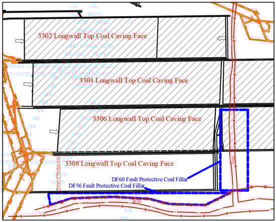
Figure 1.
Structural layout of the 3308 working face in relation to surrounding mining areas and faults.
In the shallow adjacent area of the 3308 working face, there is an extensive goaf formed by the 3306, 3304, and 3302 working faces. Due to the steep dip angle of the #3 coal seam, the overlying strata of the shallow goaf in adjacent working faces have not fully collapsed. The subsidence and collapse of overlying strata in the inclined direction of the goaf may negatively affect the coal seam and roof of the 3308 working face, which is one of the primary factors influencing mining-induced earthquakes in the 3308 working face.
Based on the mining experience of the Yangcheng Coal Mine, the 3306 working face, which has similar geological and production conditions to the 3308 working face, had already been mined before this study. The zone of destruction of the roof rocks above the post-mining space for the 3306 working face (mainly due to periodic pressure causing roof rock damage) was approximately 15 to 20 m. During the microseismic research of the 3308 working face, which was in its initial extraction stage, the zone of destruction of the roof rocks above the post-mining space was estimated to be around 25 to 30 m based on the microseismic location, source mechanism, and microseismic response before and after the high-energy mining-induced earthquake event on 20 December. After the targeted seismic measures recommended in this study were implemented at the Yangcheng Coal Mine, no further high-energy mining-induced earthquakes or rockbursts occurred, and the zone of destruction of the roof rocks above the post-mining space decreased to the 15 to 20 m range, similar to that of the 3306 working face under similar working conditions. The primary seam mined in the 3308 face is the No. 3 coal seam, which exhibits a tendency for rockburst. The seam has a dip angle ranging from 26° to 30°, with an average dip of 28°. It is black with a vitreous luster and a brownish-black streak. Compositionally, it is mainly bright coal, with lesser amounts of vitrinite, minor dark coal, and trace fiber coal. It has a stepped fracture and a banded structure, with the middle to upper portions mostly consisting of blocky, hard coal. The structure of the coal body in this face generally appears banded; however, near the faults, structural stress effects cause the coal to exhibit fractured, granular, and pulverized structures. The average coal seam thickness is 7.5 m, classifying it as a stable thick seam. The occurrence characteristics of the coal seam at the working face are shown in Figure 2.
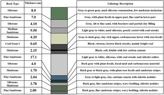
Figure 2.
Occurrence characteristics of the coal seam at the working face.
2.2. Monitoring System and Sensor Arrangement
The KJ550 stress monitoring system is primarily used for real-time stress monitoring within mine roadways and working faces. Utilizing high-sensitivity sensor devices, it collects data on surrounding rock stress changes, providing data support for early warning of mining-induced earthquakes and other geological disasters. The stress sensors used in this study are primarily designed to measure changes in the stress environment of the roadway and surrounding rock mass. These sensors operate based on the strain gauge principle, detecting deformations caused by stress changes. When stress acts on the rock mass, the strain gauge deforms, resulting in measurable changes in electrical resistance. These resistance changes are recorded and used to analyze the magnitude of the stress and its variation over time. These sensors are highly sensitive and capable of providing real-time data, which is crucial for identifying stress concentration areas and potential risk zones, especially under deep mining conditions. Its advantages lie in high monitoring accuracy and rapid response speed, enabling dynamic stress monitoring and real-time monitoring of stress concentration areas, thus assisting in disaster prediction.
The arrangement of stress sensors in roadways plays a crucial role in monitoring stress distribution and identifying potential risk areas. In this study, the sensors were deployed to ensure even distribution and effectively cover stress concentration areas, allowing for accurate measurement of stress variations over time. This approach ensures that the collected data represent the broad conditions of the roadway and surrounding areas, which is essential for mine-induced earthquake prediction analysis. Furthermore, cost is an important consideration when deploying these sensors. While the cost of sensors is relatively low compared to other mining equipment, their number and placement are optimized to enhance data accuracy while avoiding unnecessary expenses. Therefore, the monitoring scheme not only ensures data precision and broad coverage but also takes budget constraints into account. Figure 3 shows the arrangement of KJ550 stress sensors in the 3308 working face.
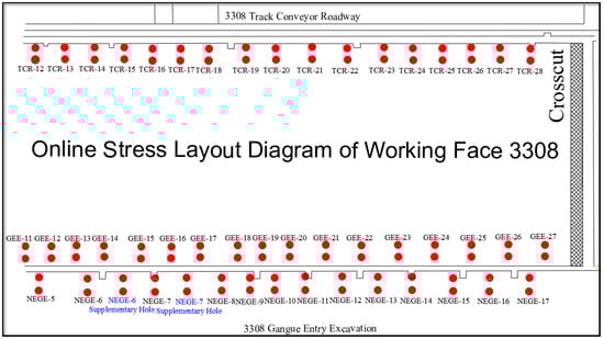
Figure 3.
Online arrangement of KJ550 stress sensors at the 3308 working face.
The SOS microseismic monitoring system, developed by the Polish Mining Research Institute, is widely applied in underground mining environments such as coal mines due to its high sensitivity and real-time data acquisition capabilities, meeting the demands of complex, high-stress mining areas. The SOS microseismic monitoring system used in the Yangcheng Coal Mine employs velocity-type sensors with a sampling frequency of 500 Hz. Through microseismic sensors positioned at various locations, it can accurately capture microseismic signals during coal and rock fracturing processes. Using algorithms such as the L1/L2 norm simplex and Newton iterative methods, the system performs source localization and energy calculations for microseismic events. This enables effective monitoring and early warning of coal and rock dynamic hazards (e.g., rockburst) and provides reliable support for predicting the development trends of dynamic phenomena like mining-induced earthquakes. Figure 4 illustrates the arrangement of effective microseismic sensors near the 3308 working face.
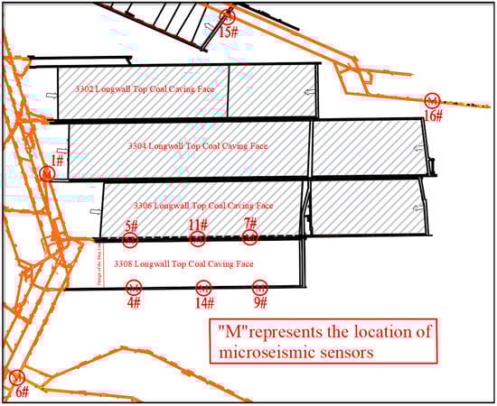
Figure 4.
Spatial arrangement of microseismic sensors around the 3308 working face at Yangcheng Coal Mine.
3. Overview and Mechanism of Mining-Induced Earthquake Events at the 3308 Working Face
3.1. Overview of Mining-Induced Earthquake Events
On 10 September 2022, a high-energy mining-induced earthquake occurred during the initial extraction phase at the 3308 fully mechanized caving face of the Yangcheng Coal Mine. According to the analysis by the mine’s SOS microseismic monitoring system, a fracture occurred in the roof ahead of the 3308 fully mechanized caving face at 14:38:25 on 10 September, with an energy release of 3.06 × 10⁵ J. Feedback from underground personnel indicated that a tremor was felt at the 3308 working face, accompanied by a sudden strong airflow from the goaf direction. Minor spalling and coal dust were observed in the advanced section of the track roadway, but there were no occurrences of rib spalling, floor heave, roof subsidence, or support damage, and no tremors were felt on the surface. This mining-induced earthquake drew the attention of local government officials and the mine leadership, leading to a halt in production at the 3308 working face until December of the same year.
On 20 December 2022, another high-energy mining-induced earthquake event occurred during the resumption of extraction at the 3308 face. According to the SOS microseismic monitoring system’s analysis, this event took place on 20 December at 20:55:42, due to damage to the floor ahead of the 3308 face, with an energy release of 1.06 × 10⁵ J. Based on site feedback, underground conditions remained safe, with no impact on personnel or equipment, and all operational conditions were normal.
Based on the dynamic manifestations observed during the two mining-induced earthquakes, as well as feedback from on-site personnel, it is evident that although neither event resulted in casualties, severe damage to roadway and mining space surrounding rock, or equipment destruction, both caused noticeable tremors felt by workers at the face and inflicted varying degrees of damage to the surrounding rock in the roadway. There was even a distinct tremor felt in the surface industrial area. Therefore, it is essential to analyze the generation mechanisms and precursor characteristics of these two high-energy mining-induced earthquake events at the working face to effectively prevent destructive rockburst hazards triggered by high-energy mining-induced earthquakes.
3.2. Analysis of Mine Pressure Manifestations in Roadways Before and After High-Energy Mining-Induced Earthquakes
When deploying stress sensors, the staff at the Yangcheng Coal Mine performed an initial calibration and established a periodic inspection cycle, with checks conducted every two days to ensure the sensors’ proper operation and data accuracy. The calibration procedure included verifying the sensor’s response to known reference loads, allowing inspectors to fine-tune its sensitivity and ensure reliable data collection. Additionally, Yangcheng Coal Mine used a calculation formula to convert the electrical signals recorded by the sensors into actual stress values, taking into account the sensor’s calibration coefficients and environmental factors. This process enabled the mine to obtain precise stress measurements, accurately reflecting the stress changes within the rock mass. These calibrated values were then used for further analysis of stress variations related to mining-induced seismic events.
where σ represents the actual stress value, Vout is the sensor’s output voltage, Vref is the reference voltage, and S is the sensitivity of the sensor. This formula allows us to convert the electrical signal into precise stress values, ensuring the reliability of the monitoring data.
Due to the limited advance of the 3308 working face, this paper focuses on analyzing the stress variations recorded by the sensors at locations 23 to 28 in the track entry and 22 to 27 in the belt roadway, as other sensors are positioned farther from the cut, with low correlation to the stress changes associated with high-energy mining-induced earthquake events.
The ten-day stress distribution of the KJ550 stress sensors in the track entry from 3 September to 12 September 2022 is shown in Figure 5. It is evident that on 11 September, sensors 23 and 25 in the track entry showed a decrease in stress, while sensor 26 recorded an increase in stress around 10 September. The response of sensor 28 was the most pronounced, showing a sharp stress drop on 7 September, followed by a rapid increase, reaching levels comparable to the initial stress at the time of sensor installation. This indicates that a stress concentration occurred around sensor 28 on the track entry side before and after the high-energy mining-induced earthquake event on 10 September.
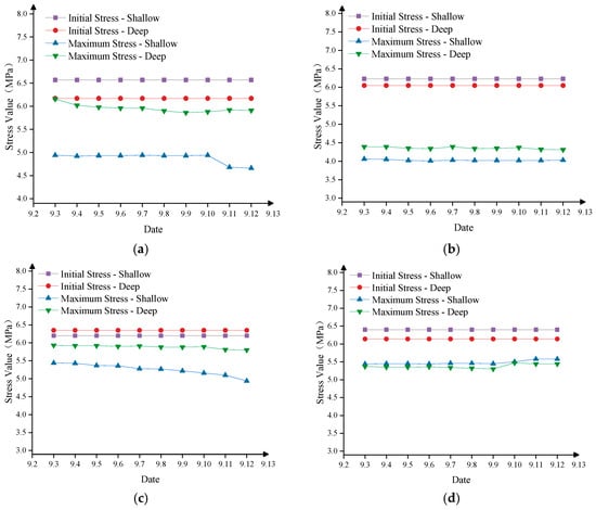
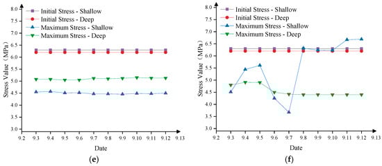
Figure 5.
Stress variation trend of track conveyor roadway sensors 23–28 on the working face (3–12 September): (a) stress graph of track conveyor roadway sensor 23 (3–12 September); (b) stress graph of track conveyor roadway sensor 24 (3–12 September); (c) stress graph of track conveyor roadway sensor 25 (3–12 September); (d) stress graph of track conveyor roadway sensor 26 (3–12 September); (e) stress graph of track conveyor roadway sensor 27 (3–12 September); (f) stress graph of track conveyor roadway sensor 28 (3–12 September).
The stress distribution over ten days (from 3 September to 12 September 2022) recorded by KJ550 stress sensors in the belt roadway is shown in Figure 6. It is evident that most sensors showed a minimal response, with low stress variation. Sensor 26 displayed a noticeable response, with stress initially decreasing on 7 September and then gradually increasing. Sensor 27 had a smaller response, with an increase in stress observed on 11 September.
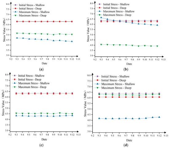
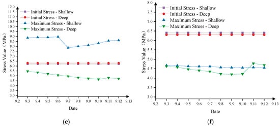
Figure 6.
Stress variation trend of belt roadway sensors 23–28 on the working face (3–12 September): (a) stress graph of belt roadway sensor 22 (3–12 September); (b) stress graph of belt roadway sensor 23 (3–12 September); (c) stress graph of belt roadway sensor 24 (3–12 September); (d) stress graph of belt roadway sensor 25 (3–12 September); (e) stress graph of belt roadway sensor 26 (3–12 September); (f) stress graph of belt roadway sensor 27 (3–12 September).
According to the trend analysis above, prior to the high-energy mining-induced earthquake on 10 September at the 3308 working face, certain stress sensors on the track roadway side had already recorded abnormal data, particularly Sensor 28, which showed a significant increase in stress from 7 September to 10 September. This indicates that stress concentration was occurring within the coal-rock mass, with elastic energy gradually accumulating. Following the high-energy event on 10 September, stress sensors on the track roadway side detected a decrease in stress, while some sensors on the belt roadway side showed an increase in stress. This phenomenon suggests that the elastic energy on the track roadway side was released during the event, relieving the stress concentration. Additionally, as the stress in the coal body was released, it also transferred to other areas, resulting in an increase in stress detected by the sensors on the belt roadway side after 10 September. This indicates that the high-energy mining-induced earthquake on 10 September occurred near the track roadway side, where there was significant stress concentration.
The ten-day stress distribution of KJ550 stress sensors in the track conveyor roadway from 13 December to 22 December is shown in Figure 7. It can be observed that most sensors recorded a slight increase in stress prior to 20 December, followed by a slight decrease after 20 December.
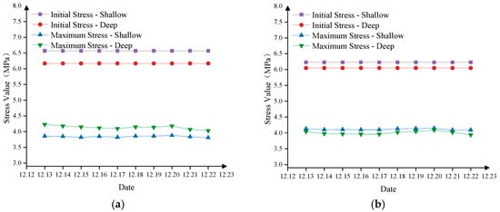
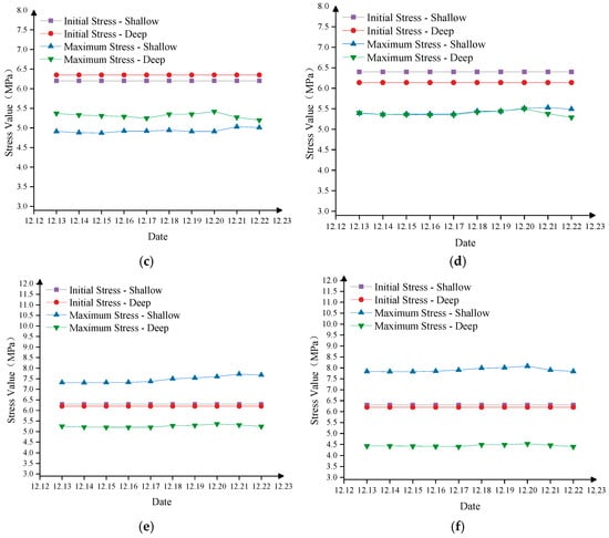
Figure 7.
Stress variation trend of track conveyor roadway sensors 23–28 on the working face (13–22 December): (a) stress graph of track conveyor roadway sensor 23 (13–22 December); (b) stress graph of track conveyor roadway sensor 24 (13–22 December); (c) stress graph of track conveyor roadway sensor 25 (13–22 December); (d) stress graph of track conveyor roadway sensor 26 (13–22 December); (e) stress graph of track conveyor roadway sensor 27 (13–22 December); (f) stress graph of track conveyor roadway sensor 28 (13–22 December).
As shown in Figure 8, the stress distribution of the KJ550 stress sensors in the belt roadway from 13 December to 22 December reveals that sensors 22, 23, 25, and 27 experienced a sudden increase in stress on 20 December, followed by a rapid decrease after the high-energy mining-induced earthquake event. This indicates a sharp rise in stress at the 3308 working face between December 19 and 20 December, pointing to a significant stress concentration in the area. The subsequent high-energy mine mining-induced earthquake event released the accumulated elastic energy, resulting in a reduction in stress levels.
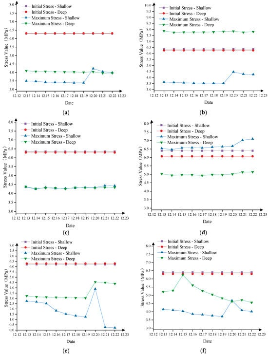
Figure 8.
Stress variation trend of belt roadway sensors 23–28 on the working face (13–22 December): (a) stress graph of belt roadway sensor 22 (13–22 December); (b) stress graph of belt roadway sensor 23 (13–22 December); (c) stress graph of belt roadway sensor 24 (13–22 December); (d) stress graph of belt roadway sensor 25 (13–22 December); (e) stress graph of belt roadway sensor 26 (13–22 December); (f) stress graph of belt roadway sensor 27 (13–22 December).
Overall, the high-energy mining-induced earthquake on 10 September was primarily reflected in the sensors on the track gate side, whereas the 20 December high-energy event was more prominently detected by sensors on the belt roadway side. In comparison, the stress variations on the belt roadway side were less distinct for the 10 September event, while the 20 December event displayed a consistent pattern across sensors on both sides.
From the observed trend, the 20 December high-energy event appears to have occurred directly at the working face or within its roof and floor. With elastic energy accumulating in these areas, both sets of stress sensors at the working face showed a clear increase in stress. When the event occurred, this elastic energy was released, leading to a subsequent drop in stress at the working face and an outward transfer of stress, visible as a stress decrease in sensors on both sides. The 10 September event, however, followed a different pattern: the sensors on the track gate side displayed a typical energy release trend of first increasing and then decreasing, while the belt roadway side exhibited an opposite trend. This suggests that the high-energy event on 10 September likely did not occur directly at the 3308 working face or its roof and floor, but rather involved stress release on the track gate side, with part of the stress transferring to the belt roadway side.
3.3. Analysis of Microseismic Activity Patterns Before and After High-Energy Mining-Induced Earthquakes
3.3.1. Time-Frequency Analysis of Microseismic Activity Patterns Before and After High-Energy Mining-Induced Earthquakes
The microseismic statistics and advance data for the 3308 working face from 25 August to 14 September are shown in Figure 9. During this period, the daily frequency of microseismic events fluctuated between 10 and 25, with maximum energy per event not exceeding 10,000 J and total energy not surpassing 40,000 J. However, on 6 September, the frequency of microseismic events surged to 32, and on 7 September it further increased to 47, with a maximum energy of 27,000 J and a total energy of 114,000 J on that day. Prior to high-energy mining-induced earthquake events, the microseismic response typically exhibits a sharp increase in frequency, with relatively low single-event and total energy levels. As a high-energy event approaches, a “silent period” in microseismic activity often emerges [20]. For instance, on 9 September, the frequency, maximum energy, and total energy of microseismic events all declined to low levels, indicating the imminent high-energy mining-induced earthquake event on 10 September.
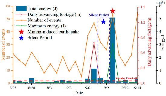
Figure 9.
Microseismic statistics and location information of the 3308 working face (25 August–14 September).
It is noteworthy that precursors to a high-energy mining-induced earthquake were evident in the 3308 working face prior to mining, with abnormal microseismic responses beginning on 6 September. However, the extraction advance on 8 September was only 0.8 m, suggesting a weak correlation between microseismic responses and the working face advance.
The microseismic statistics and advance data for the 3308 working face from 5 December to 24 December are shown in Figure 10. During regular mining, the daily microseismic frequency at the 3308 working face ranged from 10 to 34, with total energy between 10,000 J and 38,000 J, and maximum energy per event between 3500 J and 36,000 J. On 15 December, the maximum energy per microseismic event reached 36,000 J, marking a high-energy event. On the same day, the daily advance increased from 0.3 m to 0.8 m, indirectly contributing to the high-energy mining-induced earthquake on 20 December. Additionally, a microseismic “silent period” was also observed during this period, further indicating the impending high-energy event on 20 December.
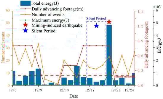
Figure 10.
Microseismic statistics and location information of the 3308 working face (5–24 December).
In mining-induced earthquake prediction and prevention research, the silent period refers to a phase before a high-energy mining-induced earthquake event when the frequency and energy levels of microseismic activity decrease markedly or even temporarily cease. This phenomenon is considered a precursor signal of energy accumulation within the rock mass, manifested by relative calm in mining-induced earthquake activity, while the actual stress field continues to increase and concentrate [21,23]. In hard roofs or rock layers, the occurrence of a silent period typically indicates an elevated risk of mining-induced earthquakes or rockbursts. Due to their high strength and low deformability, hard rock layers often do not exhibit significant deformation or fracturing during stress accumulation. As the silent period lengthens, the accumulated elastic energy grows, and upon release, may result in strong mining-induced earthquake events or even rockbursts. This phenomenon is especially common near hard roofs or large structural faults.
Therefore, recognizing the silent period is crucial for mining-induced earthquake prediction. By monitoring changes in microseismic activity frequency, mines can detect the onset of a silent period and promptly implement precautionary measures, such as reducing extraction speed, reinforcing support structures, or applying preventive pressure-relief methods to mitigate potential disaster risks. In mine areas prone to high-energy mining-induced earthquake events or rockbursts, monitoring and early warning of silent periods are essential measures for ensuring mine safety.
The microseismic event location map for the 3308 working face during the periods from 3 September to 12 September and from 13 December to 22 December is shown in Figure 11. In this map, green points represent low-energy microseismic events (0–6000 J), blue points indicate medium-energy events (6000–20,000 J), and red points represent high-energy events (greater than 20,000 J, based on the 20,000 J microseismic warning threshold set by the Yangcheng Coal Mine’s rockburst prevention design).
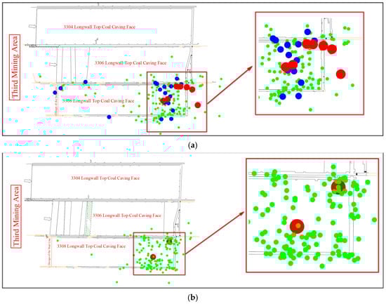
Figure 11.
Distribution map of microseismic event locations: (a) microseismic event location base map (3–12 September); (b) microseismic event location base map (13–22 December).
As observed, the low-energy events from 3 September to 12 September are nearly evenly distributed across the working face and its two roadways, with a notably higher occurrence of medium-energy events in the track roadway compared to the belt roadway. High-energy events are primarily concentrated near the belt roadway and the cutout area of the 3308 working face, with a few occurring within the DF60 fault-protected coal pillar.
From 13 December to 22 December, low-energy events were also nearly evenly distributed across the working face and its two roadways, with no medium-energy events recorded during this period. Two high-energy events occurred in this timeframe: one near the roof of the working face and the other in the roof direction on the track roadway side.
3.3.2. Calculation of Mining-Induced Earthquake Source Mechanism
This study conducted microseismic localization and source mechanism analysis for the two high-energy mining-induced earthquake events on 10 September and 20 December. The waveform diagrams for these events are shown in Figure 12 and Figure 13. Eight sensors with clearer waveforms (highlighted in red), selected from sensors 1, 4, 5, 6, 7, 9, 11, 14, 15, and 16, were used for picking arrival times and performing localization calculations.
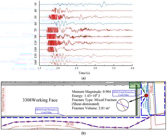
Figure 12.
Microseismic data and source mechanism of the 10 September mining-induced earthquake event: (a) original microseismic waveform; (b) source mechanism.
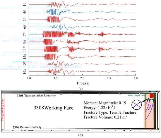
Figure 13.
Microseismic data and source mechanism of the 20 December mining-induced earthquake event: (a) original microseismic waveform; (b) source mechanism.
Assuming the source coordinates are , the coordinates of the i-th sensor are , the propagation velocity of seismic waves is , the occurrence time of the source event is t0, and the arrival time recorded by the i-th sensor is ti. The distance between the source and the sensor can then be expressed as [31]:
For multiple sensors, a set of nonlinear equations can be established to determine the source coordinates and the event occurrence time. In this study, eight sensors were selected, allowing for the formation of eight equations:
By using the least squares method or nonlinear optimization techniques to solve these nonlinear equations [32], the three-dimensional location of the seismic source and the occurrence time t0 can be obtained.
The moment tensor Mij is a second-order tensor used to describe the seismic source, with the physical significance of characterizing the mechanical features of fault slip during source rupture. The calculation formula for the moment tensor is as follows [33]:
In this formula, represents the shear modulus, reflecting the stiffness of the medium; A is the area of the rupture surface; and and are the components of the normal vector and the slip direction vector on the rupture surface, respectively.
The seismic moment Mij is the modulus of the moment tensor and can quantify the scale of the rupture event. Its calculation formula is as follows:
For a microseismic event, the volume V of the rupture body is related to the seismic moment M0 and the average slip D. The calculation formula is as follows:
In this formula, M0 is the seismic moment, is the shear modulus, and D is the average slip on the rupture surface.
In more precise source analysis, the released energy can be represented comprehensively through the seismic moment and slip amount [34]:
Moment magnitude is a measure of earthquake size in seismology, based on the seismic moment and directly related to the energy released by the source. The calculation formula for moment magnitude is as follows [35]:
In this formula, Mw represents the moment magnitude, and M0 is the seismic moment, measured in Newton-meters (N·m). The seismic moment is typically obtained through seismic wave inversion or estimated based on source parameters.
The isotropic index (ISO) is commonly used to measure whether a rupture contains an isotropic component [36,37]:
When the ISO value is close to 0, it indicates that the rupture is purely shear. A value greater than 0 suggests the presence of an isotropic component, and when ISO approaches 1, it signifies that most of the seismic moment is generated by tensile rupture.
The obtained microseismic localization and source mechanism results are shown in the figures below. The coordinates for the high-energy mining-induced earthquake event on 10 September are (11,629.29, 10,343.37, −833.27), located within the fault-protected coal pillar behind the 3308 working face, near the fault, approximately 20~40 m above the coal seam, 20–30 m from the cutout of the 3308 working face, and 30~40 m from the track roadway. The fracture type was mixed (primarily shear), with an energy of 1.43 × 10⁶ J, a moment magnitude of 0.904, and a fracture volume of 2.81 m3. During the 10 September high-energy tremor, although the mining face had only advanced 0.8 m and the gob area was relatively small with no large-scale roof sag, it is unlikely that roof failure alone would cause such a large seismic event. The microseismic location revealed that the tremor occurred in the roof of the 3306 fault protection pillar behind the 3308 panel, near the DF60 fault. This indicates that the mining disturbance from the 3308 panel affected the incompletely collapsed roof of the 3306 gob area, the DF60 fault, and the protection pillar, leading to roof instability and fault slippage.
The coordinates for the high-energy mining-induced earthquake event on 20 December are (11,598.03, 10,310.52, −845.87), located 20–30 m above the track roadway of the 3308 working face in the roof area. This event was a tensile fracture, with an energy of 1.22 × 10⁵ J, a moment magnitude of 0.19, and a fracture volume of 0.21 m3.
For the 3308 working face, rock mass failure occurring in the roof is relatively common. Regarding the two major mining-induced earthquakes, the high-energy mining-induced earthquake on 20 September occurred near the roof of the fault protection pillar of the 3306 panel, close to the DF60 fault. The high-energy mining-induced earthquake on 20 December occurred in the high-stress areas behind the 3308 longwall face.
Therefore, the location of the microseismic events is closely related to the mining activities in the 3308 panel and the expansion of the gob area. The tremors were primarily triggered by roof instability and fault slippage caused by mining-induced disturbances and stress concentrations. As the gob area behind the 3308 panel continues to expand, there remains a risk of high-energy tremors, mainly triggered by roof fractures under high static and dynamic loads, influenced by high geological stress, especially tectonic stress, and incompletely collapsed roofs. The influence of the DF56 and DF34 faults will also affect the scale of future seismic events. Moreover, the side support pressure from the shallow gob area and the uncollapsed roof will further impact the safe mining of the 3308 longwall face.
3.4. Analysis of the Mechanism of High-Energy Mining-Induced Earthquake Events
- (1)
- For the high-energy mining-induced earthquake event on 10 September:
Stress Analysis: Prior to the 10 September high-energy mining-induced earthquake event, there was a significant increase in stress on the track roadway side of the 3308 working face, which decreased following the event. However, stress on the belt roadway side increased after the event, which does not align with the typical pattern of high-energy events occurring within the working face and its roof or floor. This indicates that the seismic event did not occur within the working face itself.
Microseismic Statistical Analysis: From a microseismic perspective, the frequency of microseismic events surged on 6 September, accompanied by abnormal stress readings. Between 6 and 8 September, there was a marked increase in microseismic frequency, followed by a “silent period” on 9 September. Additionally, Sensor 28 on the track roadway side showed a sudden drop in stress on 7 September, which subsequently rose to 7.5 MPa, about 1.3 times the standard level. This combination of stress anomalies and the silent period in microseismic activity signaled the impending high-energy mining-induced earthquake event on 10 September.
Source Mechanism and Microseismic Localization: Given that the 3308 working face advanced only 0.8 m by 10 September, with a limited goaf area and no large-scale suspended roof, it is unlikely that roof fracturing alone could generate such a high-energy event. Microseismic localization shows that the event did not occur within the working face or its roof and floor but rather in the roof of the fault-protected coal pillar behind the 3308 face, near the DF60 fault. This suggests that the disturbance from mining at the 3308 face impacted the incompletely caved roof of the 3306 goaf, the DF60 fault, and the DF60-protected coal pillar of the 3306 face, leading to roof instability, fracturing, and fault slippage. Source mechanism analysis indicates this was a mixed-type fracture (primarily shear), consistent with high-angle roof fractures and fault slippage. In summary, the 10 September mining-induced earthquake event was primarily triggered by mining disturbances during the initial extraction at the 3308 face, causing sudden roof collapse in the shallow goaf of the 3306 face and the DF60-protected coal pillar, potentially accompanied by DF60 fault slippage. The sensation of vibration and sudden strong airflow reported by underground personnel further supports this conclusion. Although this mining-induced earthquake event did not cause casualties or equipment damage, it disturbed the stress balance near the cutout of the 3308 face, intensifying the stress concentration effect in that area.
- (2)
- For the high-energy mining-induced earthquake event on 10 September:
Stress Analysis: Prior to the 20 December event, stress levels on both roadways at the 3308 working face increased, followed by a decrease after the event. This aligns with the typical pattern of mine mining-induced earthquake events within the working face and its roof and floor, where stress concentration and elastic energy buildup within the coal and rock mass are relieved after the release of accumulated energy, resulting in a decrease in stress on both roadways.
Microseismic Statistical Analysis: On December 15, the energy of microseismic events significantly increased, accompanied by an increase in daily advance from 0.3 m to 0.8 m. Subsequently, microseismic activity entered a “silent period”, followed by the high-energy event on 20 December. Microseismic localization shows that this event occurred approximately 20 m above the track roadway of the 3308 working face.
Source Mechanism and Microseismic Localization: The 20 December event was characterized by tensile fracturing, with energy and magnitude consistent with microseismic events induced by roof fractures. In summary, the 20 December high-energy mining-induced earthquake event was primarily caused by the combined effects of mining activity and stress concentration leading to roof movement within the coal seam. Although this event did not result in casualties or equipment damage, it warrants attention and preventive measures to mitigate subsequent mining-induced earthquake events and rockbursts that could affect the 3308 working face.
As the goaf area of the 3308 working face continues to expand, risks of high-energy mining-induced earthquake events persist due to factors such as high ground stress (especially structural stress), fault influence, incompletely caved roofs, fault-protected coal pillars, and mining disturbances. These risks are primarily associated with roof fracturing under high static and dynamic loads. As the working face moves farther from the DF60 fault, faults on the belt roadway side, such as DF56 and DF34, may influence the scale of mining-induced earthquake events. Additionally, lateral support pressure from shallow goaf areas and the incompletely caved roof may impact the safe extraction at the 3308 working face.
In conclusion, while microseismic and stress monitoring each have strengths in identifying mining-induced earthquake events and analyzing stress distribution, relying on a single method presents clear limitations in mining-induced earthquake prediction and early warning. Microseismic monitoring cannot directly reflect dynamic stress concentration, and stress monitoring is unable to capture the spatiotemporal characteristics of microseismic activity. These limitations hinder the accurate delineation of risk areas and the effectiveness of control measures. Therefore, integrating multiple monitoring and analysis methods—including microseismic, stress, and source mechanism analyses—is essential to enhance the reliability and accuracy of mining-induced earthquake predictions and support the prevention of rockbursts during subsequent extraction at the working face.
4. Risk Assessment and Countermeasures for Mining-Induced Earthquake at the 3308 Working Face
Based on the specific conditions of the 3308 working face, this study proposes a systematic method for delineating mine mining-induced earthquake risk zones. By analyzing stress concentration areas, microseismic characteristics, and source mechanisms, mine mining-induced earthquake risk zones were identified. Subsequently, targeted control measures were developed for each risk area to enhance disaster prevention and mitigation effectiveness, ensuring the continuous safe extraction of the mine as shown in Figure 14.
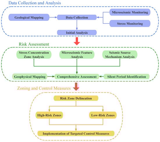
Figure 14.
Risk Zone Delineation Process.
4.1. Key Management Areas for Mining-Induced Earthquake
Based on the above analysis and the monitoring factors of mine pressure and microseismic activity during the development and extraction of the 3308 working face, key management areas for mining-induced earthquake events have been identified, as shown in Figure 15. In this figure, red indicates high-risk management areas, while blue represents low-risk management areas.
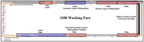
Figure 15.
Risk zone delineation for the 3308 working face.
Based on the analysis of the primary controlling factors of mining-induced earthquakes described above, the key management areas for mining-induced earthquake events are identified as follows:
- (1)
- High-Risk Management Area: Within 100 m of the initial extraction track roadway, belt roadway, and cutout. This area is delineated due to its proximity to the DF60 fault, a major stress concentration zone in the Yangcheng Coal Mine. Microseismic monitoring data show that both previous high-energy mining-induced earthquake events occurred near this area, indicating a strong energy accumulation trend. Additionally, during initial extraction, mining disturbances can easily activate the fault, triggering high-energy mining-induced earthquake events and elevating the area’s risk. Stress monitoring results indicate significant stress concentration in this area, and fault slippage is highly susceptible to influence. For example, Tang [38] analyzed the mechanical mechanisms of fault activation using numerical simulation and theoretical analysis. They studied the interaction between mining stress and fault activation and explored the impact of fault dip angle on fault rupture activation and the evolution of mining stress. Therefore, this area is designated a high-risk management zone for mining-induced earthquake events.
- (2)
- High-Risk Management Area within 100–200 m of the Cutout in the Track Roadway: This area, adjacent to the cutout, is influenced by stress conduction from the primary stress transmission, with notable initial extraction stress concentration effects, creating a high mining-induced earthquake risk. The primary stress transmission mechanism keeps the stress level in this area elevated, with microseismic monitoring data indicating frequent high-energy mining-induced earthquake events and a clear energy accumulation trend. According to the stress attenuation formula, although stress gradually decreases with distance from the cutout, it remains highly concentrated within this range. Zhang et al. [39] conducted a simulation study on the displacement, stress, and distribution of the plastic zone near the fault in the roadway. Therefore, strong management measures should be implemented here to effectively prevent seismic hazards.
Stress attenuation formula [40]:
In this formula, represents the stress at the current location, is the initial stress at the reference location, is the stress concentration factor, is the attenuation coefficient, and d is the distance from the high-stress area.
- (3)
- Low-Risk Management Area within 250–350 Meters of the Cutout in the Track Roadway: Due to the attenuation effect of primary stress transmission, stress levels in this area gradually decrease. According to the stress attenuation formula, stress exhibits an exponential decay with increasing distance from the cutout, resulting in lower stress levels within this region. Additionally, historical microseismic monitoring data indicate significantly lower energy and frequency of microseismic events in this area compared to high-risk zones, suggesting limited energy accumulation and defining it as a secondary risk zone. Being farther from major faults, this area is less affected by structural stress, making it a low-risk zone overall.
- (4)
- High-Risk Management Area within 250–350 Meters of the Cutout in the Belt roadway, Coupled with DF56 Fault: This area is designated due to the strong influence of the DF56 fault, which has a high risk of slippage. Mining activities may induce fault slippage, causing intense fluctuations in the local stress field. Microseismic monitoring results show increased frequency and energy of microseismic events in this region, with pronounced stress accumulation near the fault. Consequently, this area poses a high risk for induced mining-induced earthquake events and should be considered a high-risk management zone.
- (5)
- High-Risk Management Area within 430–500 Meters of the Cutout in the Track Roadway, Near FD34 Fault: This area is adjacent to the FD34 fault, which exhibits a significant structural stress concentration effect. Historical monitoring data indicate that slippage along the FD34 fault may trigger high-energy mining-induced earthquake events. Feng et al. [41] investigated the effects of fault dip angle (θ), fault strike angle (φ), fault zone width (d), and the distance between the working face and the fault (l) on the spatiotemporal evolution of stress and elastic potential energy. As extraction progresses, the likelihood of fault slippage increases. Microseismic monitoring results show frequent fracturing events with high energy levels, suggesting a substantial potential for mining-induced earthquakes; therefore, this area is designated as a high-risk management zone.
- (6)
- Low-Risk Management Area within 350–780 Meters of the Cutout in the Belt roadway, Near DF56 Fault: Although this area is near the DF56 fault, its considerable distance from the fault results in minimal stress concentration influence. Microseismic monitoring data show significantly lower energy and frequency of microseismic events in this area compared to other high-risk zones, with limited localized stress accumulation, indicating low seismic risk. However, given the potential for stress transmission, ongoing monitoring is still necessary, and thus, this area is designated as a low-risk management zone.
4.2. Recommendations for Mining-Induced Earthquake Prevention and Control
Before the occurrence of high-energy mining-induced earthquake events at the 3308 working face, the Yangcheng Coal Mine implemented combined support measures including anchors, nets, cables, and belts, based on the relatively weak roof support strength to ensure that the roadway support system could withstand mining-induced earthquake events up to a magnitude of 2.48. This support system was designed to resist vibration energy of up to 3.25 × 10⁶ J from beyond 20 m of the roadway surrounding rock (based on calculations in the “Anti-Burst Design for the 3308 Working Face at Yangcheng Coal Mine”). Monitoring and early warning methods included the drill cuttings method, microseismic monitoring systems, and an online stress monitoring system for rockburst, enabling multi-level monitoring.
For stress relief, the Yangcheng Coal Mine utilized drilling-based pressure relief, targeting low-to-moderate risk zones with large-diameter relief boreholes spaced no more than 1.6 m apart in a blanket layout during development. These boreholes were positioned between rows of anchor bolts to minimize damage to the support system. Each borehole had a diameter of 150 mm, a distance of 0.5 to 1.5 m from the floor, an angle consistent with the coal seam, and a depth of 20 m, with spacing adjusted according to site conditions.
Following the high-energy mining-induced earthquake event, the Yangcheng Coal Mine promptly implemented additional measures, reducing borehole spacing to “one borehole per row of bolts” and extending the depth of sidewall boreholes to 25 m. When pressure relief was insufficient, explosives were loaded into boreholes for blasting, with deep-hole blasting directed toward the fault-protected coal pillar. This series of actions significantly reduced microseismic energy; statistics showed a marked reduction in maximum and total microseismic energy in December after the high-energy mining-induced earthquake event in September, alongside a noticeable decrease in microseismic responses.
Based on existing control measures and this study, the following recommendations are proposed to further optimize high-energy mining-induced earthquake event control at the Yangcheng Coal Mine:
- (1)
- Optimize sensor networks to enhance the accuracy of microseismic localization.
- (2)
- Strengthen technical training to improve the data processing skills of personnel in microseismic and stress monitoring.
- (3)
- Adjust the working face layout to avoid the influence area of fault-protected coal pillars and redesign the cutout position; consider relocating the belt roadway layout to avoid proximity to the DF56 fault.
- (4)
- Drill high-level roof boreholes toward the goaf and fault-protected coal pillar along the 3308 track roadway for pressure relief, using hydraulic fracturing and deep-hole blasting to alleviate stress in the fault-protected coal pillar while caving in the goaf area to interrupt support pressure transmission.
- (5)
- Analyze microseismic data in-depth to ensure timely responses.
- (6)
- Optimize extraction speed and recalculate support pressures, reinforcing supports if necessary.
- (7)
- Enhance support and monitoring in key management areas, implementing timely pressure relief, caving, and other measures to prevent rockburst hazards.
These measures aim to further reduce the impact of mining-induced earthquake events on the 3308 working face, ensuring the safety and stability of the mining process. Through risk zone delineation for the 3308 working face and targeted control measures in high-risk areas, no further high-energy mining-induced earthquake events occurred at this working face from the initiation of these control measures until the end of extraction. This outcome demonstrates that the proposed risk zone delineation method and control strategy in this study effectively support safe deep coal mining and provide a sound technical and scientific basis for future mine safety.
5. Conclusions
- (1)
- A single monitoring method has significant limitations in analyzing precursors of high-energy mining-induced earthquakes and identifying hazardous areas. Although microseismic monitoring can provide information on the location and energy of fracture events within the coal-rock mass, it has difficulty directly reflecting the dynamic changes in stress concentration around the roadway surrounding rock, making it challenging to identify risk characteristics of stress accumulation zones. Meanwhile, while the coal body stress monitoring system is highly sensitive and can capture local stress changes, it cannot effectively capture the spatial distribution of fractures and mining-induced earthquake events or their temporal occurrence patterns. As a result, it is difficult to obtain complete precursor information. These limitations make it challenging for a single monitoring approach to comprehensively identify precursors of high-energy mining-induced earthquakes and to accurately delineate potential high-risk areas, thus constraining the effectiveness of mining-induced earthquake prevention and control.
- (2)
- Through integrated analysis of stress monitoring and microseismic data, the primary controlling factors of high-energy mining-induced earthquake events at the 3308 working face were identified, including stress fluctuations in high-stress concentration zones and activation of the DF60 fault and its protected coal pillar. The monitored “silent period” preceding high-energy mining-induced earthquake events indicated internal energy accumulation, a critical precursor signal for mining-induced earthquake events. Source mechanism analysis confirmed that the fracture mode of mining-induced earthquake events aligns with fault slippage characteristics.
- (3)
- By conducting comprehensive multi-parameter data analysis, the spatial-temporal evolution characteristics of high-energy mining-induced earthquake events were determined, and a method for identifying high-risk areas was proposed, leading to the delineation of high-risk management zones for mining-induced earthquake events. Measures such as dynamic pressure relief drilling and deep-hole blasting were implemented. Practical results demonstrate that the integrated hazard identification method and control measures combining microseismic and stress monitoring effectively mitigated high-energy mining-induced earthquake events, providing reliable assurance for safe production in deep coal mining.
By integrating monitoring data to delineate high-risk areas, the study provides a scientific basis for implementing targeted mining-induced earthquake risk management strategies. The findings of this study have significant practical value for improving safety in deep coal mining. By integrating monitoring data to delineate high-risk areas, the study provides a scientific basis for implementing targeted mining-induced earthquake risk management strategies. The identification of key risk zones supports the implementation of effective control measures, such as dynamic pressure relief drilling and deep-hole blasting, which have been proven to mitigate mining-induced earthquake hazards and ensure safe mining operations. Furthermore, the methods proposed in this study can be integrated into existing monitoring systems, providing early warnings and enabling timely preventive measures to minimize potential losses.
Despite the promising results, several limitations must be acknowledged. First, the study focused on the 3308 working face, and further validation of the proposed method in different mining settings and geological conditions is necessary to ensure its generalizability. Second, while the integration of stress and microseismic data provided valuable insights, other factors such as geological heterogeneity and the effects of mining-induced fractures on surrounding rock stability remain underexplored. Future research should focus on developing more advanced modeling techniques to account for these complex factors and improve the predictive capability of the monitoring system. Additionally, the potential use of artificial intelligence (AI) and machine learning techniques for real-time data processing and analysis could further enhance the accuracy of seismic hazard forecasting and risk mitigation strategies.
Author Contributions
Conceptualization, E.W.; Data curation, Z.L. and J.Q.; Formal analysis, J.L.; Investigation, W.S.; Methodology, W.S.; Supervision, Y.Z.; Validation, W.S.; Writing—original draft, W.S.; Writing—review and editing, W.S. All authors contributed to the study conception and design and all authors commented on previous versions of the manuscript. All authors have read and agreed to the published version of the manuscript.
Funding
This research was funded by National Natural Science Foundation of China (Grant number: 51934007).
Institutional Review Board Statement
Not applicable.
Informed Consent Statement
Not applicable.
Data Availability Statement
The raw data supporting the conclusions of this article will be made available by the authors on request.
Conflicts of Interest
The authors declare no conflict of interest.
References
- Tomassi, A.; Trippetta, F.; de Franco, R.; Ruggieri, R. From Petrophysical Properties to Forward-Seismic Modeling of Facies Heterogeneity in the Carbonate Realm (Majella Massif, Central Italy). J. Pet. Sci. Eng. 2022, 211, 110242. [Google Scholar] [CrossRef]
- Lyu, P.; Geng, Y. Unified Mechanism of Rock Burst Induced by Coal Mine Earthquake and Its Activity and Response Characteristics. Shock. Vib. 2023, 2023, 2145765. [Google Scholar] [CrossRef]
- Li, T.; Cai, M.F.; Cai, M. A Review of Mining-Induced Seismicity in China. Int. J. Rock Mech. Min. Sci. 2007, 44, 1149–1171. [Google Scholar] [CrossRef]
- Chen, D.; Wang, Z.; Yue, S.; Xie, S.; He, F.; Tian, C.; Jiang, Z.; Liang, D.; Qi, B. Study on Surrounding Rock Control of Withdrawal Space in Fully Mechanized Caving Mining of a 19 m Extra-Thick Coal Seam. Appl. Sci. 2024, 14, 9694. [Google Scholar] [CrossRef]
- Zhang, C.; Jin, G.; Liu, C.; Li, S.; Xue, J.; Cheng, R.; Wang, X.; Zeng, X. Prediction of Rockbursts in a Typical Island Working Face of a Coal Mine through Microseismic Monitoring Technology. Tunn. Undergr. Space Technol. 2021, 113, 103972. [Google Scholar] [CrossRef]
- Li, X.; Chen, S.; Wang, E.; Li, Z. Rockburst Mechanism in Coal Rock with Structural Surface and the Microseismic (MS) and Electromagnetic Radiation (EMR) Response. Eng. Fail. Anal. 2021, 124, 105396. [Google Scholar] [CrossRef]
- Zhao, J.-S.; Jiang, Q.; Lu, J.-F.; Chen, B.-R.; Pei, S.-F.; Wang, Z.-L. Rock Fracturing Observation Based on Microseismic Monitoring and Borehole Imaging: In Situ Investigation in a Large Underground Cavern under High Geostress. Tunn. Undergr. Space Technol. 2022, 126, 104549. [Google Scholar] [CrossRef]
- Lu, C.-P.; Dou, L.-M.; Zhang, N.; Xue, J.-H.; Wang, X.-N.; Liu, H.; Zhang, J.-W. Microseismic Frequency-Spectrum Evolutionary Rule of Rockburst Triggered by Roof Fall. Int. J. Rock Mech. Min. Sci. 2013, 64, 6–16. [Google Scholar] [CrossRef]
- Liu, X.; Zhang, Z.; Wang, E.; Wang, X.; Yang, B.; Wang, H. Characteristics of Electromagnetic Radiation Signal of Coal and Rock under Uniaxial Compression and Its Field Application. J. Earth Syst. Sci. 2019, 129, 34. [Google Scholar] [CrossRef]
- Li, H.; Qiao, Y.; Shen, R.; He, M. Electromagnetic Radiation Signal Monitoring and Multi-Fractal Analysis during Uniaxial Compression of Water-Bearing Sandstone. Measurement 2022, 196, 111245. [Google Scholar] [CrossRef]
- Ma, K.; Wang, H.; Liao, Z.; Peng, Y.; Wang, K. Precursor of Microseismic Energy and Stress Evolution Induced by Rockburst in Coal Mining: A Case Study from Xiashijie, Shannxi, China. Geomech. Geophys. Geo-Energy Geo-Resour. 2022, 8, 134. [Google Scholar] [CrossRef]
- Zhan, K.; Wen, X.; Wang, X.; Kong, C. A Method for Characterization of Stress Concentration Degree of Coal Mine Roadway Surrounding Rock. J. Geophys. Eng. 2023, 20, 699–711. [Google Scholar] [CrossRef]
- Liu, C.; Zhao, G.; Xu, W.; Meng, X.; Huang, S.; Zhou, J.; Wang, Y. Experimental Investigation on Failure Process and Spatio-Temporal Evolution of Rockburst in Granite with a Prefabricated Circular Hole. J. Cent. South Univ. 2020, 27, 2930–2944. [Google Scholar] [CrossRef]
- Yin, S.; Li, Z.; Wang, E.; Liu, Y.; Niu, Y.; Yang, H. Damage Status and Failure Precursors of Different Coal Impact Types Based on Comprehensive Monitoring of Infrared Radiation and Acoustic Emission. Appl. Sci. 2024, 14, 8792. [Google Scholar] [CrossRef]
- Wang, J.; Apel, D.B.; Xu, H.; Wei, C.; Skrzypkowski, K. Evaluation of the Effects of Yielding Rockbolts on Controlling Self-Initiated Strainbursts: A Numerical Study. Energies 2022, 15, 2574. [Google Scholar] [CrossRef]
- Barthwal, H.; van der Baan, M. Microseismicity Observed in an Underground Mine: Source Mechanisms and Possible Causes. Géoméch. Energy Environ. 2020, 22, 100167. [Google Scholar] [CrossRef]
- Holub, K.; Rušajová, J.; Holečko, J. Particle Velocity Generated by Rockburst during Exploitation of the Longwall and Its Impact on the Workings. Int. J. Rock Mech. Min. Sci. 2011, 48, 942–949. [Google Scholar] [CrossRef]
- Dou, L.; Chen, T.; Gong, S.; He, H.; Zhang, S. Rockburst Hazard Determination by Using Computed Tomography Technology in Deep Workface. Saf. Sci. 2012, 50, 736–740. [Google Scholar] [CrossRef]
- Yan, X.; Xu, R.; Zhan, K.; Wen, X.; Wang, C.; Li, Z.; Zhang, Q. Inversion of Mining-Induced Stress Field Based on Focal Mechanism Solutions: A Case Study of the 63upper06 Working Face in Dongtan Coal Mine. Front. Earth Sci. 2024, 12, 1405154. [Google Scholar] [CrossRef]
- Moment Tensor Inversion and Stress Evolution of Coal Pillar Failure Mechanism|Rock Mechanics and Rock Engineering. Available online: https://link.springer.com/article/10.1007/s00603-022-02783-1 (accessed on 10 October 2024).
- He, S.; Song, D.; Li, Z.; He, X.; Chen, J.; Li, D.; Tian, X. Precursor of Spatio-Temporal Evolution Law of MS and AE Activities for Rock Burst Warning in Steeply Inclined and Extremely Thick Coal Seams Under Caving Mining Conditions. Rock Mech. Rock Eng. 2019, 52, 2415–2435. [Google Scholar] [CrossRef]
- Liu, X.; Zhang, S.; Wang, E.; Zhang, Z.; Wang, Y.; Yang, S. Multi-Index Geophysical Monitoring and Early Warning for Rockburst in Coalmine: A Case Study. Int. J. Environ. Res. Public Health 2023, 20, 392. [Google Scholar] [CrossRef]
- Li, X.; Wang, E.; Li, Z.; Liu, Z.; Song, D.; Qiu, L. Rock Burst Monitoring by Integrated Microseismic and Electromagnetic Radiation Methods. Rock Mech. Rock Eng. 2016, 49, 4393–4406. [Google Scholar] [CrossRef]
- Li, Z.; Dou, L.; Cai, W.; Wang, G.; He, J.; Gong, S.; Ding, Y. Investigation and Analysis of the Rock Burst Mechanism Induced within Fault-Pillars. Int. J. Rock Mech. Min. Sci. 2014, 70, 192–200. [Google Scholar] [CrossRef]
- He, M.C.; Zhao, F.; Cai, M.; Du, S. A Novel Experimental Technique to Simulate Pillar Burst in Laboratory. Rock Mech. Rock Eng. 2015, 48, 1833–1848. [Google Scholar] [CrossRef]
- Liu, X.; Xu, G.; Zhang, C.; Kong, B.; Qian, J.; Zhu, D.; Wei, M. Time Effect of Water Injection on the Mechanical Properties of Coal and Its Application in Rockburst Prevention in Mining. Energies 2017, 10, 1783. [Google Scholar] [CrossRef]
- He, J.; Dou, L.; Gong, S.; Li, J.; Ma, Z. Rock Burst Assessment and Prediction by Dynamic and Static Stress Analysis Based on Micro-Seismic Monitoring. Int. J. Rock Mech. Min. Sci. 2017, 93, 46–53. [Google Scholar] [CrossRef]
- Guo, W.; Ma, X.; Wen, Y.; Cao, X. Stress Evolution and Rock Burst Prevention in Triangle Coal Pillars under the Influence of Penetrating Faults: A Case Study. Appl. Sci. 2024, 14, 8585. [Google Scholar] [CrossRef]
- Zhu, S.; Feng, Y.; Jiang, F. Determination of Abutment Pressure in Coal Mines with Extremely Thick Alluvium Stratum: A Typical Kind of Rockburst Mines in China. Rock Mech. Rock Eng. 2016, 49, 1943–1952. [Google Scholar] [CrossRef]
- Zhu, S.; Feng, Y.; Jiang, F.; Liu, J. Mechanism and Risk Assessment of Overall-Instability-Induced Rockbursts in Deep Island Longwall Panels. Int. J. Rock Mech. Min. Sci. 2018, 106, 342–349. [Google Scholar] [CrossRef]
- Howe, M.; Ekstrom, G.; Nettles, M. Improving Relative Earthquake Locations Using Surface-Wave Source Corrections. Geophys. J. Int. 2019, 219, 297–312. [Google Scholar] [CrossRef]
- Monteiller, V.; Got, J.L.; Virieux, J.; Okubo, P. An Efficient Algorithm for Double-Difference Tomography and Location in Heterogeneous Media, with an Application to the Kilauea Volcano. J. Geophys. Res.-Solid Earth 2005, 110, B12306. [Google Scholar] [CrossRef]
- Zhu, L.; Ben-Zion, Y. Parametrization of General Seismic Potency and Moment Tensors for Source Inversion of Seismic Waveform Data. Geophys. J. Int. 2013, 194, 839–843. [Google Scholar] [CrossRef]
- Okubo, K.; Bhat, H.S.; Rougier, E.; Marty, S.; Schubnel, A.; Lei, Z.; Knight, E.E.; Klinger, Y. Dynamics, Radiation, and Overall Energy Budget of Earthquake Rupture With Coseismic Off-Fault Damage. J. Geophys. Res.-Solid Earth 2019, 124, 11771–11801. [Google Scholar] [CrossRef]
- Ekström, G.; Dziewonski, A.M. Evidence of Bias in Estimations of Earthquake Size. Nature 1988, 332, 319–323. [Google Scholar] [CrossRef]
- Duan, J.; Shum, C.K.; Guo, J.; Huang, Z. Uncovered Spurious Jumps in the GRACE Atmospheric De-Aliasing Data: Potential Contamination of GRACE Observed Mass Change. Geophys. J. Int. 2012, 191, 83–87. [Google Scholar] [CrossRef]
- Julian, B.R.; Miller, A.D.; Foulger, G.R. Non-Double-Couple Earthquakes 1. Theory. Rev. Geophys. 1998, 36, 525–549. [Google Scholar] [CrossRef]
- Tang, L.; Tu, S.; Tu, H.; Zhang, L.; Miao, K.; Zhao, H.; Ma, J. Interaction Law between Mining Stress and Fault Activation and the Effect of Fault Dip Angle in Longwall Working Face. Sci. Rep. 2024, 14, 25654. [Google Scholar] [CrossRef] [PubMed]
- Zhang, Z.; Chen, F.; Li, N.; He, M. Influence of Fault on the Surrounding Rock Stability for a Mining Tunnel: Distance and Tectonic Stress. Adv. Civ. Eng. 2019, 2019, 2054938. [Google Scholar] [CrossRef]
- Butcher, A.; Luckett, R.; Kendall, J.-M.; Baptie, B. Seismic Magnitudes, Corner Frequencies, and Microseismicity: Using Ambient Noise to Correct for High-Frequency Attenuation. Bull. Seismol. Soc. Amer. 2020, 110, 1260–1275. [Google Scholar] [CrossRef]
- Feng, X.; Zhao, X.; Ding, Z.; Hu, Q.; Wang, D.; Cao, Z. Numerical Study on the Influence of Fault Orientation on Risk Level of Fault Slip Burst Disasters in Coal Mines: A Quantitative Evaluation Model. Environ. Earth Sci. 2024, 83, 94. [Google Scholar] [CrossRef]
Disclaimer/Publisher’s Note: The statements, opinions and data contained in all publications are solely those of the individual author(s) and contributor(s) and not of MDPI and/or the editor(s). MDPI and/or the editor(s) disclaim responsibility for any injury to people or property resulting from any ideas, methods, instructions or products referred to in the content. |
© 2024 by the authors. Licensee MDPI, Basel, Switzerland. This article is an open access article distributed under the terms and conditions of the Creative Commons Attribution (CC BY) license (https://creativecommons.org/licenses/by/4.0/).