Abstract
This study investigates the performance of a centrifugal radial turbine within an Organic Rankine Cycle (ORC) system, focusing on operation beyond the design point due to variable waste heat sources. With the goal of integrating the turbine into optimal ORC operating conditions, its performance was analyzed using R245fa as the working fluid over three stages with varying numbers of blades. A detailed computational analysis was performed using Ansys CFX software (Version 2020 R2) with the k-ω SST turbulence model using thermodynamic data from the NIST Refprop database. The results showed significant discrepancies when operating beyond the design point. At an inlet pressure of 780 kPa, the turbine internal power was calculated to be 120 kW—double the manufacturer’s maximum of 60 kW—and the mass flow rate exceeded 6 kg/s compared to the design value of 2.72 kg/s. These results highlight the challenges of adapting the turbine to fluctuating waste heat conditions, as factors such as tip clearance, blade geometry, and high outlet pressure have a significant impact on efficiency and system performance.
1. Introduction
The growing global demand for energy [,], coupled with the imperative to reduce greenhouse gas emissions [,], has intensified the search for efficient and sustainable energy conversion technologies [,]. Waste heat recovery systems have emerged as a promising solution to enhance energy efficiency in various industrial processes by converting low-grade thermal energy into useful power []. Among these systems, the Organic Rankine Cycle (ORC) has gained significant attention due to its ability to utilize heat sources at relatively low temperatures, which are often inadequate for conventional steam-based power cycles [,].
The ORC employs organic working fluids with favorable thermodynamic properties, enabling efficient energy conversion from low-temperature heat sources such as industrial waste heat [], geothermal energy [,], and biomass [,]. The selection and optimization of key components within the ORC, particularly the expander or turbine, are of critical importance for maximizing system performance []. Axial [], radial inflow [], and radial turbines [] are often preferred in small-to-medium-scale ORC applications due to their compact size, simplicity, and ability to handle significant volume flow rates and pressure ratios. While turbines offer numerous advantages [], their performance in ORC systems is highly sensitive to operating conditions, particularly when exposed to variable waste heat sources [,]. Industrial processes frequently exhibit fluctuations in waste heat availability due to changes in production rates, process interruptions, or seasonal variations. Exceeding the design point of a turbine can result in inefficiencies [,], mechanical stresses [], and a reduction in lifespan []. Consequently, it is crucial to comprehend the behavior of turbines under variable operating conditions to optimize ORC systems and ensure reliable and efficient energy recovery. The current research in this field has concentrated on the design and optimization of radial turbines for specific operational conditions [,]. In some studies, multiple operational points have been taken into account []. In article [], the authors adopt a multipoint design method to enhance turbine performance under complex operating conditions. Their findings demonstrate that implementing this multipoint optimization approach effectively eliminates flow separation across a spectrum of operating conditions, thereby ensuring optimal turbine performance even when operating outside the designed parameters. Nevertheless, these considerations have not yet permitted the construction of a loss model that would enable the prediction of turbine operating parameters over a broad range of operating characteristics at the design stage.
However, there is a paucity of research addressing the challenges associated with turbine operation under fluctuating waste heat conditions. The conventional approach often involves designing turbines for a fixed operating point, which may not be optimal when the heat source varies. This gap necessitates a systematic investigation into turbine adaptability and performance across a range of operating conditions, with the aim of developing designs that can maintain high efficiency despite variations in waste heat input.
The objective of this study is to numerically investigate the performance of a multi-stage radial turbine under variable waste heat conditions relevant to ORC applications. By employing advanced CFD techniques, the research aims to analyze the turbine’s behavior beyond its design point, identify performance limitations, and propose solutions to enhance adaptability and efficiency. The significance of this work lies in its potential to inform the design of turbines capable of operating effectively across a spectrum of conditions, thereby maximizing energy recovery from variable waste heat sources. The primary objectives of this study are twofold: firstly, to evaluate the turbine’s efficiency, power output, and flow characteristics under different inlet pressures and rotational speeds; secondly, to identify the aerodynamic losses and mechanical challenges associated with operating beyond the design point.
By addressing these challenges, this study contributes to the broader field of sustainable energy systems, offering insights that can enhance the viability and efficiency of ORC applications utilizing variable waste heat sources. The findings are pertinent not only to engineers and researchers specializing in turbomachinery and thermodynamics but also to stakeholders in industries where waste heat recovery can play a pivotal role in energy conservation and emission reduction.
2. Methods
In order to prepare the computational model for analysis, a detailed examination of the provided turbine geometry was conducted. The centrifugal radial turbine’s flow system is comprised of two fundamental components: the stationary stator (Figure 1) and the rotating rotor (Figure 2). Both components are of critical importance in defining the flow characteristics and overall performance of the turbine. The stator and rotor are composed of three distinct stages (Figure 3), each featuring a varying number of blades. The initial stage comprises 12, 18, and 24 blades, while the subsequent stage incorporates 12 and 15 blades. The final stage is characterized by 16 and 21 blades. The variation in blade count and blade geometry across stages is designed to manage the changing flow velocities and pressures throughout the turbine. A clearance of 0.2 mm has been defined for the tips situated in both the stator and rotor rows.
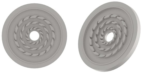
Figure 1.
Radial turbine stator cross-section.
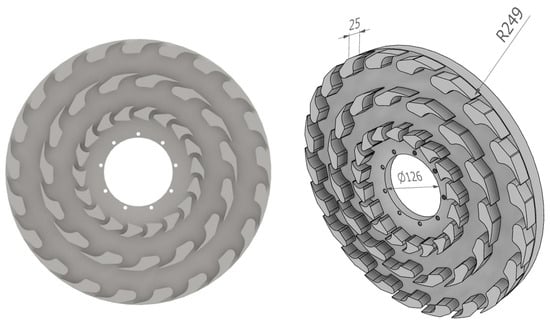
Figure 2.
Radial turbine rotor cross-section.

Figure 3.
Radial turbine blades geometry.
In computational modeling, particular attention was paid to the quality of the mesh in order to guarantee accurate and stable simulation results. The mesh was designed in accordance with rigorous criteria for face angles, edge length ratios, and element volume ratios. In particular, the following limits were set for the mesh:
- Maximum face angle: 165°;
- Minimum face angle: 15°;
- Maximum edge length ratio: 500;
- Connectivity number: 12;
- Maximum volume ratio: 10;
- Minimum volume ratio: 0.
These parameters were selected with great care in order to optimize the quality of the mesh. The application of face angle limits serves to circumvent the potential for numerical inaccuracies that may arise from the presence of highly skewed elements. By establishing a maximum face angle of 165° and a minimum of 15°, the mesh is configured to retain element shapes that facilitate stable and accurate computations. The edge length ratio limit of 500 ensures that elements do not become excessively elongated, which can have a detrimental impact on convergence and solution accuracy. The volume ratio limits regulate the variation in element size between adjacent elements, facilitating a seamless transition in element sizes throughout the mesh. Setting the connectivity number to 12 helps maintain an optimal number of elements connected to a node, reducing computational errors associated with highly connected nodes. The mesh quality criteria were implemented with the objective of achieving a balance between computational efficiency and the accuracy of the simulation results, thereby ensuring reliable predictions of the turbine performance. The radial turbine flow path was calculated on a fine grid comprising approximately eight million elements. In the course of grid independence checks, grids of up to 12 million elements per whole passage were investigated. It was found that the maximum relative differences between corresponding values of isentropic efficiency for the finest investigated mesh of 12 million nodes (reference values), with respect to those of the mesh of 8 million nodes calculated, were less than 0.25% (Figure 4).
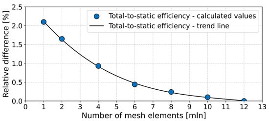
Figure 4.
Grid sensitivity based on the turbine total-to-static efficiency.
The thermodynamic properties of the working fluid, R245fa (Pentafluoropropane, HFC-245fa), were obtained from the NIST Refprop database (Version 10). This database provides accurate real-fluid properties essential for simulating compressible flows with phase change potentials, ensuring reliable results under varying pressure and temperature conditions. The simulations were conducted using Ansys CFX (Version 2020 R2). The Reynolds-Averaged Navier–Stokes (RANS) equations were solved using a second-order spatial discretization scheme to achieve enhanced accuracy in capturing flow gradients and to minimize numerical diffusion. The Frozen Rotor interface was employed between the stationary stator and the rotating rotor domains (Figure 5). This approach models the interaction between stationary and rotating components by maintaining a fixed relative position, thereby capturing the steady-state interaction without the computational expense of a transient simulation. The k-ω Shear Stress Transport (SST) turbulence model was employed with automatic wall functions. The k-ω SST model combines the advantages of the k-ε and k-ω models, providing accurate predictions of flow separation and adverse pressure gradients, which are common in turbomachinery flows. In order to control the time scale, an automatic time scale was employed, with a conservative length scale option and a time scale factor of 1.6. This configuration facilitates a balance between convergence speed and solution accuracy. The residual target was set to 1 × 10⁻5 to guarantee sufficient convergence of the simulations. The automatic wall function adapts to the local mesh refinement, ensuring appropriate near-wall treatment without the need for excessively fine meshes. The impact of tip clearance on leakage flows and overall turbine efficiency was explicitly modeled in the simulations, with a tip clearance of 0.2 mm being used. It is well-established that tip clearance losses significantly affect the performance of turbomachinery, with this being particularly relevant in the context of small-scale turbines. Consequently, this was an important aspect of the computational model.
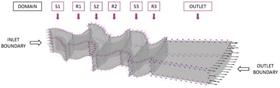
Figure 5.
Computational domain for the radial turbine simulation.
A series of simulations were conducted across the range of inlet and outlet pressures to evaluate the turbine’s performance under various operating conditions. This approach allowed for the assessment of the turbine’s adaptability to fluctuating waste heat sources and the identification of any performance limitations when operating beyond the design point. The operating conditions were established to reflect the turbine’s operation beyond the design point, with the objective of accommodating variable waste heat sources. The inlet pressure to the turbine was varied from 330 kPa to 780 kPa in order to simulate different operating scenarios, while the outlet pressure was set between 150 kPa and 200 kPa, in alignment with the analyzed condenser pressures in ORC systems. The temperature of the working fluid at the turbine inlet was determined using the saturation temperature corresponding to the specified inlet pressure (Figure 6). An additional superheat of 5 K was added to prevent condensation within the turbine, ensuring that the fluid remained in the superheated vapor region. The entropy of the working fluid was then calculated along the specified isobar for accurate thermodynamic property definition.
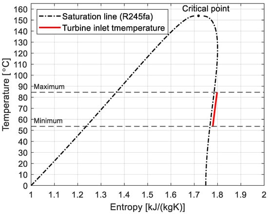
Figure 6.
Temperature-entropy diagram of R245fa.
3. Results
This section presents the findings of the computational analysis conducted on the centrifugal radial turbine under various operating conditions. The performance evaluation encompasses an array of rotational speeds (3600 rpm, 3000 rpm, and 1500 rpm), inlet pressures spanning a range from 330 kPa to 780 kPa, and outlet pressures set at 150 kPa, 170 kPa, and 200 kPa. The aim is to evaluate the efficiency, power output, mass flow rate, and axial force of the turbine under these conditions in order to ascertain their influence on overall performance.
3.1. Turbine Performance at a Rotor Outlet Pressure of 150 kPa
This section presents the results of the computational analysis conducted on a turbine operating at a constant outlet pressure of 150 kPa. Simulations were conducted for three rotational speeds (3600 rpm, 3000 rpm, and 1500 rpm) and various inlet pressures (ranging from 330 kPa to 780 kPa) in order to evaluate the turbine’s performance under different operating conditions and to ascertain the impact of rotational speed and inlet pressure on efficiency and power output.
For the turbine operating at 3600 rpm, the isentropic efficiency exhibited a range of 66.16% to 70.6%. Upon reducing the rotational speed to 3000 rpm, the efficiency values exhibited a slight decline, ranging from 60% to 67%. The lowest efficiencies were observed at 1500 rpm, with values ranging from 38.6% to 47.9%. These findings suggest that higher rotational speeds contribute to enhanced turbine efficiency under the specified conditions.
A comparable pattern was discerned in the mechanical power generated by the turbine. The highest power output of 132.5 kW was achieved at an inlet pressure of 780 kPa and a rotational speed of 3600 rpm. Conversely, the lowest power output of 25.4 kW occurred at an inlet pressure of 380 kPa and a rotational speed of 1500 rpm. Figure 7 illustrates the relationship between power output and efficiency across the different operating conditions.
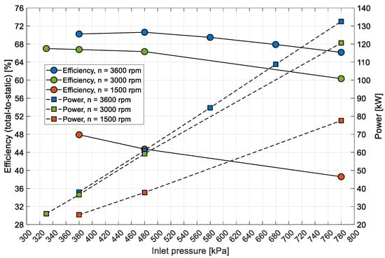
Figure 7.
Comparison of efficiency and power output at varying inlet pressures and rotational speeds.
In order to evaluate the turbine’s regulatory capabilities and adapt the cycle parameters to its characteristics, the mass flow rate through the turbine was determined as a function of the inlet pressure (Figure 8). At an inlet pressure of 330 kPa, the mass flow rate was approximately 2.6 kg/s, increasing to nearly 6.3 kg/s at an inlet pressure of 780 kPa. The significant variation in mass flow rate with inlet pressure underscores the necessity for precise control of operating conditions to guarantee optimal turbine performance within the ORC system.
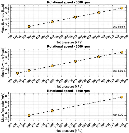
Figure 8.
Variation in mass flow rate with inlet pressure for different flow conditions.
Figure 9 illustrates the axial force exerted on the turbine rotor, a pivotal factor in the selection of thrust bearings, and comprehensive mechanical design considerations. The lowest axial force in the direction of flow was 14.6 kN, obtained at an inlet pressure of 330 kPa. The highest axial force of 64.3 kN was recorded at the maximum inlet pressure of 780 kPa. As there were negligible differences in axial forces at different rotational speeds, the results are presented solely for a rotational speed of 3000 rpm.
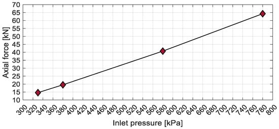
Figure 9.
Axial force at varying inlet pressures.
These findings underscore the considerable influence of rotational speed and inlet pressure on the turbine’s efficiency, power output, mass flow rate, and axial force. A comprehensive understanding of these relationships is crucial for optimizing turbine operation and effectively integrating it into an ORC system, particularly when harnessing variable waste heat sources. The results indicate that operating the turbine at higher rotational speeds and carefully managing inlet pressures can enhance performance but also necessitate meticulous mechanical design to accommodate increased axial forces.
The velocity vectors (Figure 10), streamlines (Figure 11, Figure 12 and Figure 13), and entropy contours (Figure 14 and Figure 15) were subjected to analysis for the centrifugal turbine operating at an inlet pressure of 780 kPa and a rotational speed of 3000 rpm. Profile losses were observed on the suction side of the rotor blades across the first, second, and third stages of the turbine. These losses occurred over a significant portion of the blade height, indicating areas where the flow separated from the blade surface, which ultimately resulted in a reduction in efficiency. Moreover, a substantial blade wake was discernible in the stator blades of the second and third stages. This wake formation contributes to additional flow disturbances and energy losses, which have an adverse effect on the efficiency of the flow system. The presence of wakes indicates that the flow leaving the stator blade is not uniform, which can cause unsteady loading on downstream rotor blades and reduce overall performance. At the outlet of the final stage of the turbine, a notable increase in velocity was observed. This acceleration corresponds to an augmentation in kinetic energy, which is not entirely converted into useful work by the turbine. Consequently, this results in the generation of exit losses from the blade system. The high kinetic energy of the exhaust flow represents a potential source of energy that is not currently being extracted, indicating that the turbine could benefit from design modifications to better harness this energy. These observations identify critical areas within the turbine where aerodynamic losses occur, emphasizing the significance of optimizing blade geometry and flow passages. Reducing profile losses on the rotor blades and minimizing wake formation in the stator blades could result in improvements in turbine efficiency. Furthermore, addressing the high exit velocities may necessitate the redesign to recover some of the kinetic energy, thereby enhancing the overall performance of the ORC system.
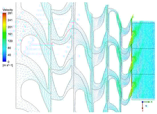
Figure 10.
Velocity vectors in the turbine at the mid-span.
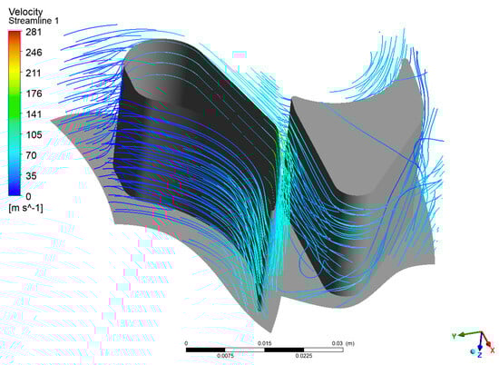
Figure 11.
Streamline in the first-stage passage.
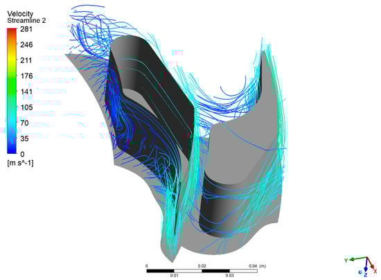
Figure 12.
Streamline in the second-stage passage.
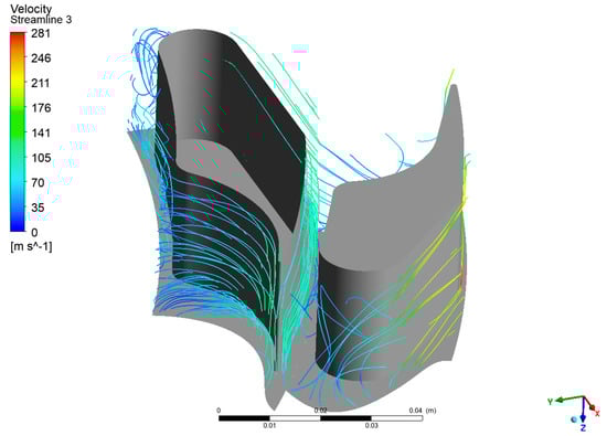
Figure 13.
Streamline in the third-stage passage.
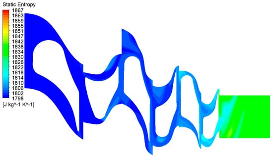
Figure 14.
Static entropy contours in the turbine at the mid-span.
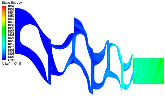
Figure 15.
Static entropy contours in the turbine at the hub.
As with the previous case, this section presents the velocity vectors (Figure 16), streamlines (Figure 17, Figure 18 and Figure 19), and static entropy contours (Figure 20 and Figure 21) of the centrifugal turbine operating at an inlet pressure of 380 kPa and a rotational speed of 3000 rpm. The flow analysis under these conditions revealed a similar pattern of losses, as previously observed, namely, profile losses on the suction side of the rotor blades and edge losses on the stator blades of the second and third stages. It is noteworthy that the areas of the second and third stages of the turbine exhibited a notable intensification of losses. This increase in losses is particularly significant, as it indicates that the turbine’s performance deteriorates when operating at lower inlet pressures. The intensified losses may be attributed to enhanced flow separation, increased secondary flows, or other adverse flow phenomena that become more pronounced under these conditions. These findings emphasize the vulnerability of the second and third stages to alterations in operational parameters. The augmented losses underscore the necessity for prospective design modifications to the blade geometry or adjustments to the operational conditions to mitigate efficiency reductions. Addressing these issues is crucial for optimizing the turbine’s performance when operating beyond the design point, particularly in applications involving variable waste heat sources where inlet conditions can fluctuate significantly.
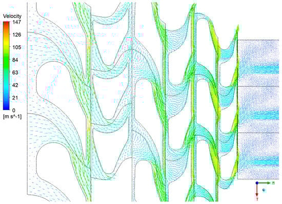
Figure 16.
Velocity vectors in the turbine at the mid-span.
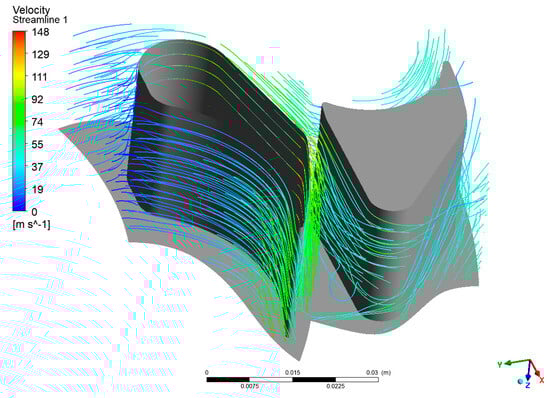
Figure 17.
Streamline in the first-stage passage.
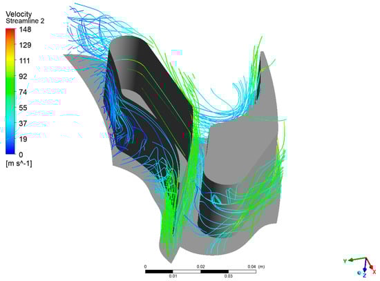
Figure 18.
Streamline in the second-stage passage.
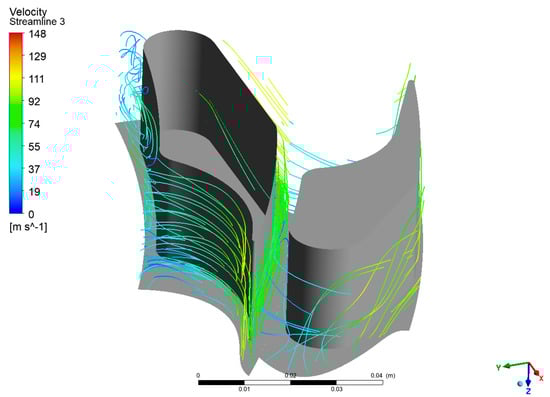
Figure 19.
Streamline in the third-stage passage.
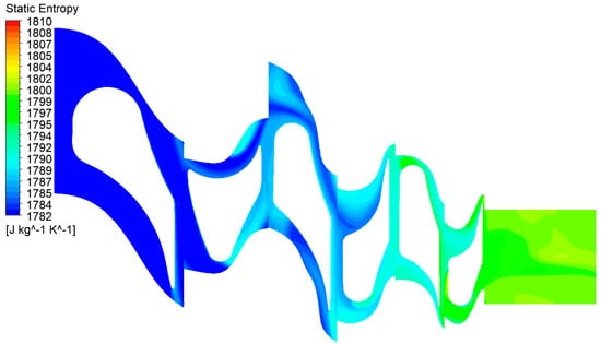
Figure 20.
Static entropy contours in the turbine at the mid-span.
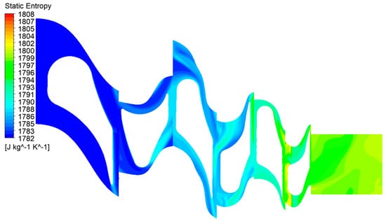
Figure 21.
Static entropy contours in the turbine at the hub.
3.2. Turbine Performance at a Rotor Outlet Pressure of 170 kPa
Figure 22 depicts the relationship between turbine efficiency and power output as functions of inlet pressure for three rotational speeds (3600 rpm, 3000 rpm, and 1500 rpm) at a constant rotor outlet pressure of 170 kPa. The efficiencies obtained under these conditions were comparable to those achieved at an outlet pressure of 150 kPa, indicating that the slight increase in outlet pressure did not significantly impact the turbine’s efficiency. However, the power outputs at each operating point exhibited a decline of approximately 5 kW in comparison to those observed at an outlet pressure of 150 kPa. This reduction in power output can be attributed to the decreased pressure ratio across the turbine due to the higher outlet pressure. A smaller pressure drop results in less expansion of the working fluid, thereby generating less mechanical work. Despite the decrease in power output, maintaining efficiencies comparable to those at lower outlet pressures suggests that the turbine operates effectively even with variations in outlet pressure, albeit with reduced power generation. These findings are significant for applications where the condenser pressure—and consequently the turbine’s outlet pressure—may fluctuate due to external factors or system limitations. An understanding of the turbine’s performance under these conditions facilitates the optimization of the overall ORC system, ensuring reliable operation even when operating parameters deviate from the original design specifications.
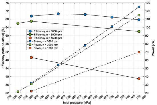
Figure 22.
Comparison of efficiency and power output at varying inlet pressures and rotational speeds.
3.3. Turbine Performance at a Rotor Outlet Pressure of 200 kPa
At an outlet pressure of 200 kPa from the rotor, the results were compiled exclusively for a rotational speed of 3000 rpm (Figure 23). Under these conditions, the turbine efficiencies ranged from 64% to 67.3%, with power outputs varying from 24 kW to 107 kW. Significantly higher efficiency values were obtained at lower inlet pressure values, indicating that the design point of this flow system can be assumed to be close to the assumed pressure values. A comparison of the performance at an outlet pressure of 170 kPa with that at 200 kPa revealed a decrease in power output by several kilowatts.
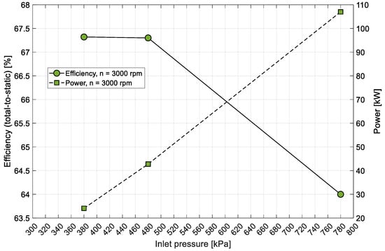
Figure 23.
Comparison of efficiency and power output at varying inlet pressures.
Figure 24 demonstrates that at an inlet pressure of 380 kPa, the aerodynamic expansion process is less intense. The gradual pressure gradient observed from the inlet to the outlet indicates that the flow is relatively stable, with lower aerodynamic forces acting on the rotor blades. The diminished aerodynamic loading on the blade surfaces minimizes the potential for flow separation or recirculation zones, thereby promoting a more laminar flow behavior. In contrast, Figure 25, which depicts a significantly higher inlet pressure of 780 kPa, demonstrates a markedly stronger aerodynamic process. The steeper pressure gradient from the inlet to the outlet highlights the rapid acceleration of the working fluid as it passes through the turbine. The high-pressure difference across the blade passages creates stronger aerodynamic forces, driving a more intense expansion process. Consequently, the working fluid experiences significant increases in velocity and kinetic energy. This results in higher Mach numbers and enhanced flow acceleration, characteristics typical of turbines operating under high-loading conditions. It should be noted that the aforementioned conditions result in elevated levels of aerodynamic losses, predominantly due to an increase in exit velocity losses.
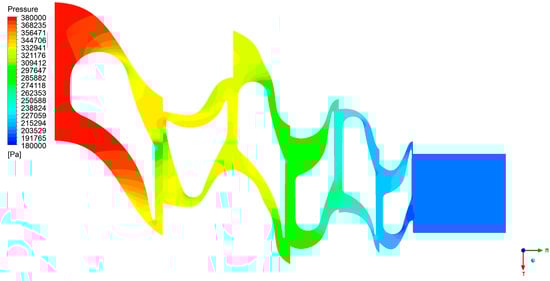
Figure 24.
Pressure contours in the turbine at the mid-span under low-pressure operating conditions.
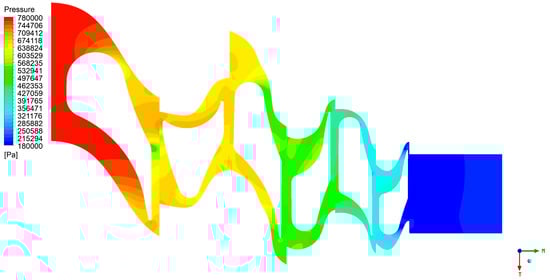
Figure 25.
Pressure contours in the turbine at the mid-span under high-pressure operating conditions.
3.4. Turbine Performance at a Rotational Speed of 3000 rpm
To evaluate the impact of condenser pressure on turbine power output at a rotational speed of 3000 rpm, a comparative analysis was conducted across a broader and a narrower expander operational range (Figure 26). A notable decline in the generated power was observed as a result of the diminished isentropic enthalpy drop in the turbine, which can be attributed to the elevated outlet pressure in the condenser. A decrease in power output of 12.47 kW and 13.6 kW was observed between outlet pressures of 150 kPa and 200 kPa, respectively, for inlet pressures of 380 kPa and 780 kPa. This limitation in available power is significant, as the power drop constitutes up to 34% of the predicted power output in cases of lower power generation. These findings indicate that the outlet pressure plays a crucial role in the electrical energy production of the ORC unit. It can be reasonably assumed that an ORC system that is unable to meet its planned electrical energy production targets may be the result of an excessively low condensation temperature. Therefore, it is essential to consider the impact of condenser pressure and condensation temperature on turbine performance in order to optimize the reliability of the ORC system.
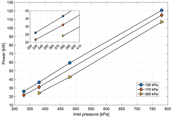
Figure 26.
Power output vs. inlet pressure for various outlet pressures.
3.5. Turbine Efficiency Comparison
Table 1 presents a comparative analysis of the efficiency obtained for the turbine under examination. The values presented in the reference case are derived from experimental tests of the turbine conducted by the manufacturer. In turn, Cases 1 and 2 are the results of CFD simulations conducted by the author. In the absence of precise data regarding the operating pressure of the turbine, the maximum power presented by the manufacturer (55 kW at a turbine rotational speed of 3600 rpm) was used as a reference point. In order to facilitate comparison with the reference case, two further cases were prepared, differing in terms of inlet and outlet pressure and inlet temperature. In comparison to the reference case, the efficiency of Case 1 and Case 2, respectively, was found to be 3.05 and 3.49 percentage points (pp) lower. This discrepancy may be attributed to a number of factors. Firstly, the operating pressure and operating temperature of the turbine, which were declared by the manufacturer, are not known. This is an important element, as it may be the case that the expander design point has not been reached. Secondly, the available tip clearance above the turbine rotor blades in the geometric model may differ from the clearance obtained in the finished product. In this case, it can be postulated that the clearance has been reduced in comparison to the available CAD model. Thirdly, the manufacturer’s data lack clarity regarding the measurement methodology and the margin of error. It is possible that the obtained results are included in the total measurement error of the manufacturer’s experimental tests. Ultimately, in both cases, the obtained results are similar to each other and do not differ significantly from the reference case, which provides an excellent starting point for further experimental tests of this expander.

Table 1.
Comparison of efficiency for different cases.
4. Conclusions
This study employs a methodological approach that combines detailed geometric modeling with advanced numerical methods for evaluating the performance of a centrifugal radial turbine under variable operating conditions. By addressing critical factors such as tip clearance, blade geometry, and thermodynamic properties of the working fluid, the simulations provide valuable insights into the turbine’s behavior beyond the design point, informing potential redesigns and optimizations for integration into ORC systems utilizing variable waste heat sources.
The findings indicated that the efficiency and power output of the turbine are significantly influenced by the rotational speed, inlet pressure, and outlet pressure. When operating beyond the design point, discrepancies were observed between the expected and actual performances, indicating that the turbine might encounter difficulties adapting to fluctuating waste heat conditions. It was determined that aerodynamic losses, including profile losses on rotor blades, wake formation in stator blades, and high exit velocities, were the primary factors contributing to the observed reduction in efficiency.
In order to address these challenges, a number of recommendations have been proposed. Modifications to the operating conditions, particularly a reduction in inlet pressure, can align the turbine’s performance with the design specifications, ensuring that the mass flow rates and power outputs remain within the expected ranges. A comprehensive redesign of the blade geometry may prove an effective means of mitigating aerodynamic losses, enhancing flow characteristics, and improving overall efficiency. Moreover, the meticulous selection and optimization of mechanical components, such as thrust bearings, are crucial to accommodating the augmented axial forces resulting from variable operating conditions. It is also imperative to regulate the outlet pressure by optimizing condenser conditions to maintain the desired pressure ratio across the turbine and maximize energy production.
In conclusion, the effective integration of the turbine into ORC systems with variable waste heat sources necessitates both operational adjustments and design modifications. By addressing the identified issues, the efficiency and performance of the turbine can be enhanced, thereby improving energy recovery and the overall viability of ORC applications.
Funding
This research received no external funding.
Institutional Review Board Statement
Not applicable.
Informed Consent Statement
Not applicable.
Data Availability Statement
The original contributions presented in this study are included in this article; further inquiries can be directed to the author.
Acknowledgments
Calculations were carried out at the Academic Computer Centre in Gdańsk.
Conflicts of Interest
The author declares no conflicts of interest.
References
- Bollino1, C.A.; Asdrubali, F.; Polinori, P.; Bigerna, S.; Micheli, S.; Guattari, C.; Rotili, A. A Note on Medium- and Long-Term Global Energy Prospects and Scenarios. Sustainability 2017, 9, 833. [Google Scholar] [CrossRef]
- Waite, M.; Cohen, E.; Torbey, H.; Piccirilli, M.; Tian, Y.; Modi, V. Global Trends in Urban Electricity Demands for Cooling and Heating. Energy 2017, 127, 786–802. [Google Scholar] [CrossRef]
- Ramanathan, V.; Feng, Y. Air Pollution, Greenhouse Gases and Climate Change: Global and Regional Perspectives. Atmos. Environ. 2009, 43, 37–50. [Google Scholar] [CrossRef]
- Purohit, P.; Höglund-Isaksson, L. Global Emissions of Fluorinated Greenhouse Gases 2005-2050 with Abatement Potentials and Costs. Atmos. Chem. Phys. 2017, 17, 2795–2816. [Google Scholar] [CrossRef]
- Mancò, G.; Tesio, U.; Guelpa, E.; Verda, V. A Review on Multi Energy Systems Modelling and Optimization. Appl. Therm. Eng. 2024, 236, 121871. [Google Scholar] [CrossRef]
- Tefera, W.M.; Kasiviswanathan, K.S. A Global-Scale Hydropower Potential Assessment and Feasibility Evaluations. Water Resour. Econ. 2022, 38, 100198. [Google Scholar] [CrossRef]
- Lecompte, S.; Ntavou, E.; Tchanche, B.; Kosmadakis, G.; Pillai, A.; Manolakos, D.; de Paepe, M. Review of Experimental Research on Supercritical and Transcritical Thermodynamic Cycles Designed for Heat Recovery Application. Appl. Sci. 2019, 9, 2571. [Google Scholar] [CrossRef]
- Chen, W.; Fu, B.; Zeng, J.; Luo, W. Research on the Operational Performance of Organic Rankine Cycle System for Waste Heat Recovery from Large Ship Main Engine. Appl. Sci. 2023, 13, 8543. [Google Scholar] [CrossRef]
- Corigliano, O.; Algieri, A.; Fragiacomo, P. Turning Data Center Waste Heat into Energy: A Guide to Organic Rankine Cycle System Design and Performance Evaluation. Appl. Sci. 2024, 14, 6046. [Google Scholar] [CrossRef]
- Loni, R.; Najafi, G.; Bellos, E.; Rajaee, F.; Said, Z.; Mazlan, M. A Review of Industrial Waste Heat Recovery System for Power Generation with Organic Rankine Cycle: Recent Challenges and Future Outlook. J. Clean. Prod. 2021, 287, 125070. [Google Scholar] [CrossRef]
- Eyerer, S.; Dawo, F.; Wieland, C.; Spliethoff, H. Advanced ORC Architecture for Geothermal Combined Heat and Power Generation. Energy 2020, 205, 117967. [Google Scholar] [CrossRef]
- Jankowski, M.; Borsukiewicz, A.; Wiśniewski, S.; Hooman, K. Multi-Objective Analysis of an Influence of a Geothermal Water Salinity on Optimal Operating Parameters in Low-Temperature ORC Power Plant. Energy 2020, 202, 117666. [Google Scholar] [CrossRef]
- Meriño Stand, L.; Valencia Ochoa, G.; Duarte Forero, J. Energy and Exergy Assessment of a Combined Supercritical Brayton Cycle-Orc Hybrid System Using Solar Radiation and Coconut Shell Biomass as Energy Source. Renew. Energy 2021, 175, 119–142. [Google Scholar] [CrossRef]
- Oyekale, J.; Petrollese, M.; Cau, G. Multi-Objective Thermo-Economic Optimization of Biomass Retrofit for an Existing Solar Organic Rankine Cycle Power Plant Based on NSGA-II. Energy Rep. 2020, 6, 136–145. [Google Scholar] [CrossRef]
- Zywica, G.; Kaczmarczyk, T.Z.; Ihnatowicz, E. A Review of Expanders for Power Generation in Small-Scale Organic Rankine Cycle Systems: Performance and Operational Aspects. Proc. Inst. Mech. Eng. Part A J. Power Energy 2016, 230, 669–684. [Google Scholar] [CrossRef]
- Weiß, A.P.; Popp, T.; Müller, J.; Hauer, J.; Brüggemann, D.; Preißinger, M. Experimental Characterization and Comparison of an Axial and a Cantilever Micro-Turbine for Small-Scale Organic Rankine Cycle. Appl. Therm. Eng. 2018, 140, 235–244. [Google Scholar] [CrossRef]
- Uusitalo, A.; Turunen-Saaresti, T.; Honkatukia, J.; Dhanasegaran, R. Experimental Study of Small Scale and High Expansion Ratio ORC for Recovering High Temperature Waste Heat. Energy 2020, 208, 118321. [Google Scholar] [CrossRef]
- Kaczmarczyk, T.Z.; Żywica, G.; Ihnatowicz, E. The Impact of Changes in the Geometry of a Radial Microturbine Stage on the Efficiency of the Micro CHP Plant Based on ORC. Energy 2017, 137, 530–543. [Google Scholar] [CrossRef]
- Zhao, Y.; Liu, G.; Li, L.; Yang, Q.; Tang, B.; Liu, Y. Expansion Devices for Organic Rankine Cycle (ORC) Using in Low Temperature Heat Recovery: A Review. Energy Convers. Manag. 2019, 199, 111944. [Google Scholar] [CrossRef]
- Jiménez-Arreola, M.; Pili, R.; Dal Magro, F.; Wieland, C.; Rajoo, S.; Romagnoli, A. Thermal Power Fluctuations in Waste Heat to Power Systems: An Overview on the Challenges and Current Solutions. Appl. Therm. Eng. 2018, 134, 576–584. [Google Scholar] [CrossRef]
- Petrollese, M.; Cocco, D. A Multi-Scenario Approach for a Robust Design of Solar-Based ORC Systems. Renew. Energy 2020, 161, 1184–1194. [Google Scholar] [CrossRef]
- Kang, S.H. Design and Preliminary Tests of ORC (Organic Rankine Cycle) with Two-Stage Radial Turbine. Energy 2016, 96, 142–154. [Google Scholar] [CrossRef]
- Klimaszewski, P.; Klonowicz, P.; Witanowski, Ł.; Suchocki, T.; Lampart, P.; Ihnatowicz, E.; Antczak, Ł.; Zaniewski, D.; Jedrzejewski, Ł. Evaluation of the Performance of an Axial One-Stage 10kW Turbogenerator through Experimental Testing. In Proceedings of the 7th International Seminar on ORC Power System (ORC 2023), Seville, Spain, 4–6 September 2023; Editorial Universidad de Sevilla: Seville, Spain, 2024; pp. 149–158. [Google Scholar]
- Banaszkiewicz, M. Numerical Investigations of Crack Initiation in Impulse Steam Turbine Rotors Subject to Thermo-Mechanical Fatigue. Appl. Therm. Eng. 2018, 138, 761–773. [Google Scholar] [CrossRef]
- Zych, P.; Żywica, G. Fatigue Analysis of the Microturbine Rotor Disc Made of 7075 Aluminium Alloy Using a New Hybrid Calculation Method. Materials 2022, 15, 834. [Google Scholar] [CrossRef] [PubMed]
- Peng, N.; Wang, E.; Wang, W. Design and Analysis of a 1.5 KW Single-Stage Partial-Admission Impulse Turbine for Low-Grade Energy Utilization. Energy 2023, 268, 126631. [Google Scholar] [CrossRef]
- Xu, G.; Zhao, G.; Quan, Y.; Liang, R.; Li, T.; Dong, B.; Fu, J. Design and Optimization of a Radial-Axial Two-Stage Coaxial Turbine for High-Temperature Supercritical Organic Rankine Cycle. Appl. Therm. Eng. 2023, 227, 120365. [Google Scholar] [CrossRef]
- Witanowski, Ł.; Klonowicz, P.; Lampart, P.; Ziółkowski, P. Multi-Objective Optimization of the ORC Axial Turbine for a Waste Heat Recovery System Working in Two Modes: Cogeneration and Condensation. Energy 2023, 264, 126187. [Google Scholar] [CrossRef]
- Song, P.; Sun, J.; Wang, S.; Wang, X. Multipoint Design Optimization of a Radial-Outflow Turbine for Kalina Cycle System Considering Flexible Operating Conditions and Variable Ammonia-Water Mass Fraction. Energies 2022, 15, 8748. [Google Scholar] [CrossRef]
- Baccioli, A.; Ferrari, L.; Vizza, F.; Desideri, U. Feasibility Analysis of Coupling an ORC to a MGT in a Biogas Plant. Energy Procedia 2019, 158, 2311–2316. [Google Scholar] [CrossRef]
Disclaimer/Publisher’s Note: The statements, opinions and data contained in all publications are solely those of the individual author(s) and contributor(s) and not of MDPI and/or the editor(s). MDPI and/or the editor(s) disclaim responsibility for any injury to people or property resulting from any ideas, methods, instructions or products referred to in the content. |
© 2024 by the author. Licensee MDPI, Basel, Switzerland. This article is an open access article distributed under the terms and conditions of the Creative Commons Attribution (CC BY) license (https://creativecommons.org/licenses/by/4.0/).