Abstract
This study designed and validated a power control algorithm tailored to the unique characteristics of a 100 kW wind turbine equipped with an independent generator torque control system within the Power Conversion System (PCS). Unlike conventional power control methods based on the Programmable Logic Controller (PLC), the independent generator torque control in the PCS estimates the generator speed based on the voltage signal and performs the generator torque control without any interference from the PLC. The conventional power control algorithm in the PLC was modified so that the PLC could perform the power control by the blade pitch control only. Furthermore, a mode transition algorithm was designed to improve the shortcomings of the mode switch previously used for transitioning between the torque and pitch control modes. To verify the performance, a simulation environment similar to actual control conditions was established using a commercial analysis program, and dynamic simulations were conducted. Additionally, for the experimental validation, the proposed control algorithm was applied to a scaled wind turbine, and wind tunnel tests were performed. The results of the simulations and wind tunnel tests confirmed the operational performance of the PCS’s torque control and the improved control transition logic. The proposed control algorithm could be specifically applied to medium-sized wind turbines employing a sensorless generator speed estimation method and independent generator torque control in the PCS.
1. Introduction
Recent trends in wind turbine development emphasize the need for large-diameter rotors and tall towers to efficiently utilize wind resources and maximize energy production. Major global wind turbine manufacturers have been continuously conducting research on the development of ultra-large wind turbine models with capacities exceeding 14 MW, and some models have already been developed and released [1,2,3]. On the other hand, with the growing need for micro-grid systems in regions where establishing a national power grid is challenging, such as islands, small- to medium-sized wind turbines are being highlighted as key energy sources [4,5,6,7]. Consequently, continuous research and development of small- and medium-sized wind turbine models are required. While small wind turbines come in various configurations depending on the type of generation and purpose, horizontal-axis lift-type turbines are known to be the most advantageous in terms of power generation efficiency [8,9]. For this reason, small wind turbines with capacities above several tens of kW and medium-sized wind turbines are generally designed as horizontal-axis lift-type models, similar to large wind turbines [10,11].
The power control algorithm that determines the operational performance of horizontal-axis lift-type wind turbines can be categorized into generator torque control and blade pitch control. Generally, torque control is used in the operating regions known as Region II and Region II-1/2, where wind speeds are below the rated wind speed. In contrast, blade pitch control is used in the operating region known as Region III, where wind speeds exceed the rated wind speed [12,13].
The main objective of torque control is to maximize the efficiency of wind turbines or, in the case of turbines equipped with gearboxes, to reduce the loads related to the drive train mode [14]. According to the research by Mandic et al., a torque control strategy was designed and proposed to eliminate torque noise acting on the drive train’s final stage, and to reduce the torque fluctuations that cause excessive damage. The proposed algorithm was validated using the FAST simulation model. Although the quantitative results were not provided, the reduction in torque fluctuations was confirmed through time-series and frequency domain data analysis [15]. Brandetti et al. designed an optimal Tip Speed Ratio (TSR) tracking control for torque control. The proposed optimal TSR tracking control calculates the torque command through Proportional–Integral (PI) control based on the error between the operating TSR, derived from predicted wind speed, and the optimal TSR. The simulation results showed a reduction in the overall power by about 2%, but the torque fluctuation rate was reduced by approximately 80% [16]. Barambones et al. proposed a maximum power tracking control using an aerodynamic torque estimator. The proposed control algorithm was validated through a test bench, and although no quantitative results were provided in the literature, it was concluded that the control was efficient and successful based on time-series data [17].
Pitch control algorithms have been applied for purposes such as power control and load reduction, using techniques like peak shaving [18,19], feed-forward control [20], and individual pitch control [21,22]. In the study validating peak shaving, the control algorithm was updated on a Programmable Logic Controller (PLC) and demonstrated on a 100 kW wind turbine. Peak shaving reduces the thrust and loads acting on the wind turbine by pre-emptively sending pitch commands in the Region II-1/2 operating area. The demonstration results showed that the standard deviation of the rotor speed was reduced by approximately 8% [19]. Bao et al. proposed a feed-forward control using wind speed measurements from LIDAR and designed the algorithm by adding a feed-forward logic to the conventional pitch control algorithm. Although no quantitative comparison was presented, the simulation results indicated load reduction, as evidenced by the analysis of the auto power spectrum of the tower accelerations in both fore-aft and side-to-side directions [20]. Petrović et al. designed and applied individual pitch control to reduce the loads on wind turbines. The simulation results confirmed a significant reduction in the 1P component of the blade bending moment [22].
The generator torque and blade pitch control commands for wind turbines are calculated through algorithms uploaded to the PLC, which acts as the brain of the wind turbine [23,24,25]. Typically, the generator speed is input from sensors such as encoders, and the torque and blade pitch commands are calculated according to the control objectives. These commands are then sent to the Power Conversion System (PCS) or the blade pitch actuator controller.
In some wind turbines, the torque command is not generated by the PLC but directly by the PCS, which carries out torque control [26]. This independent torque control within the PCS estimates the generator speed using the generator’s voltage signals and applies the corresponding current command to the generator based on the required generator reaction torque [27]. In other words, this control system uses a current signal schedule based on the voltage signals during the process of calculating the generator torque command. The PCS torque control independently generates control commands and sends them to the wind turbine, separate from the algorithm operating within the PLC. Meanwhile, the PLC calculates the blade pitch commands for pitch control, independently of the PCS torque control.
In systems where independent PCS torque control is applied, the control algorithms used in conventional systems, where the generator reaction torque and blade pitch angle commands are calculated by the PLC, cannot be directly applied. These algorithms must be appropriately modified to suit the changed operating environment.
Therefore, in this study, a power control algorithm was designed for wind turbines equipped with independent PCS torque control, which had not been considered in previous research, and its performance was experimentally validated. Additionally, to compare the performance of the proposed algorithm with that of a conventional wind turbine, where both the torque and pitch control are executed by the PLC, a control algorithm that performs both torque and pitch control in the PLC was designed [27,28]. To ensure a smooth transition between the control strategies of Region II and Region III during power control, the Set Point Smoother (SPS) method, proposed in the previous literature, was slightly modified [29], and a control transition logic considering only pitch control was designed. The performance of the proposed control algorithm was validated through dynamic simulations, as well as wind tunnel experiments using a scaled wind turbine model under conditions that included turbulent wind and sensor noise. The contributions of this study can be summarized as follows:
- A power control algorithm was designed for medium-sized wind turbines with independent PCS torque control by modifying conventional wind turbine control algorithms.
- To improve the performance of the control transition logic applied in previous research, an SPS considering only pitch control was implemented.
- The operational performance of power control using PLC-based torque and pitch control, PCS-based torque control, and PLC-based pitch control was compared in a dynamic simulation environment.
- Experimental validation was conducted using a scaled wind turbine model under turbulent conditions and sensor noise in a wind tunnel to simulate real-world scenarios.
2. Wind Turbine and Control Algorithm
2.1. Target Wind Turbine
The wind turbine targeted in this study is a 100 kW turbine designed and manufactured for commercial use, which is currently undergoing installation and system optimization for field validation. Additionally, this wind turbine is designed with three blades to enable integrated pitch control and has a mechanism similar to that of typical large wind turbines. Its specifications include a hub height of 30 m, a rotor diameter of 24 m, a rated rotor speed of 50 rpm, and a maximum power coefficient of approximately 0.45 at a TSR of 7.3. Figure 1 shows the shape of the targeted wind turbine, and Table 1 presents its brief specifications. Wind turbine modeling was performed using commercial software based on the specifications provided by the manufacturer.

Figure 1.
Target wind turbine (100 kW model).

Table 1.
Specification of target wind turbine (100 kW model).
2.2. Control Algorithm
The control algorithm for the targeted wind turbine was designed considering the independent generator torque control of the PCS, applying only pitch control and control transition logic. In previous studies targeting the same wind turbine, a power control strategy commonly used in large wind turbine control systems was adopted, where both torque control and pitch control were handled by the PLC, and a mode switch was used for control mode transitions [19,28]. However, this study involved the design of a controller for an environment where independent generator torque control is performed by the PCS. Additionally, to improve any potential degradation in the operational performance that may arise during the application of the PCS’s independent generator torque control, an algorithm was proposed and designed to replace the previously used mode switch. Verification of the designed controller was conducted through simulations using the Bladed (version 4.12) program, and the control algorithm was implemented as an external controller in Dynamic Link Library (DLL) format. Figure 2 shows the overall schematic of the power control algorithm considering the PCS torque control, and the details related to the design are described in the following section.
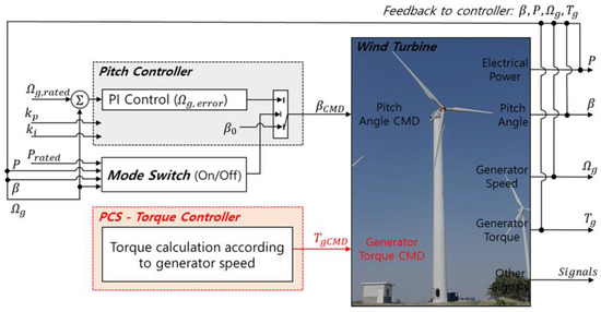
Figure 2.
Overall schematic of the power control algorithm considering the PCS torque control.
2.2.1. Power Regulation Algorithm
The power control of the targeted wind turbine, which is managed by the PLC, was designed to apply only pitch control. Typically, the pitch control of a wind turbine operates to maintain rated power in regions exceeding the rated wind speed, such as Region III. Pitch control uses PI or Proportional–Integral–Derivative (PID) control to maintain the rated generator speed, and this study adopted PI control [12,13]. Figure 3 shows the structure of the pitch PI control, where the measured generator speed and the error from the rated generator speed serve as inputs for the PI control. In this case, the control mode is input as a value of 0 or 1 based on the output of the mode switch logic for control mode transitions. When 0 is input, the control algorithm perceives the current operating condition as Region II and calculates the fine pitch angle to be transmitted as the pitch command. Conversely, when 1 is input, it recognizes the current operating condition as Region III and transmits the pitch command calculated through the PI control [13].
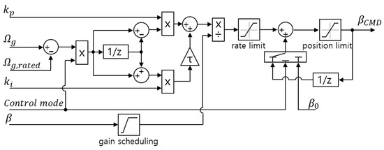
Figure 3.
Structure of the pitch PI control algorithm [13].
In the actual targeted wind turbine, torque control was implemented through the PCS torque control, which cannot be managed by the PLC. In this study, to implement the PCS torque control in the simulation, the generator torque values corresponding to the generator speed applied in the PCS were formatted as a schedule, ensuring that there were no other parameters or signals influencing the calculation of torque commands aside from the generator speed. That is, the PCS torque control generates torque commands independently of the output values of the mode switch logic.
2.2.2. Mode Switching Logic
The control transition logic uses the current operating state of the wind turbine to determine and decide on the appropriate control mode. The mode switch applied in previous studies utilizes feedback from the rated power, measured generator power, rated generator speed, measured generator speed, fine pitch angle, and measured pitch angle to assess the control mode [13]. Figure 4 shows the structure of the mode switch. The S-R flip-flop logic circuit receives an input signal of 0 or 1, determined by the operating state of the wind turbine, and generates an output signal of 0 or 1 based on the truth table presented in Table 2. The output signal passes through a NOT logic gate and is output as the final value of the mode switch, where 0 corresponds to Region II and 1 corresponds to Region III, thus contributing to the execution of control based on these operating regions. However, the mode switch has limitations, as it causes a sudden decrease in generator torque and generator power at the moment of transition from pitch control to torque control. Although the application of the PCS torque control alleviates the tendency for a sudden decrease in generator torque and power, it still shows a persistent tendency for reduction across the entire operational range. To overcome these limitations, the previously proposed Set Point Smoother (SPS) was modified and applied [29], and the design process excluded torque control, focusing solely on pitch control.
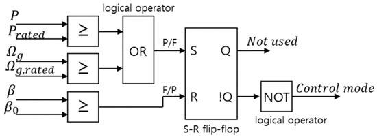
Figure 4.
Structure of the mode switch [13].
Table 2.
Truth table of the S-R flip-flop logic circuit.
Equation (1) shows the formula for calculating the change in the generator speed used in the design of the SPS, utilizing the rated generator torque, measured generator torque, gain value, and rated generator speed as inputs. The change in the generator speed is used to calculate the error value for the pitch PI control. Typically, the error applied in the pitch PI control is calculated as the difference between the rated generator speed and the measured generator speed. However, by adding the change in the generator speed to the error calculation term, the error value can be altered, thereby changing the pitch control commands. Figure 5 illustrates the overall schematic of the power control algorithm with the modified control transition logic applied. Equation (2) presents the formula for error calculation, and the structure of the pitch PI control is modified and applied as shown in Figure 3 and Figure 6.
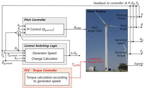
Figure 5.
Overall schematic of the proposed power control algorithm.
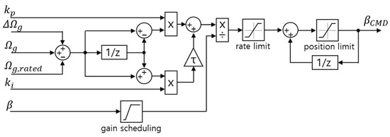
Figure 6.
Structure of the pitch PI control algorithm with SPS.
When considering the operating area of Region II, the measured generator torque is always lower than the rated generator torque, resulting in the generator speed change being negative. In this case, according to Equation (1), the generator speed error value increases in the negative direction, and the pitch PI control generates a negative pitch command to overcome this error. However, the blade pitch angle has a minimum pitch angle limit (low limit) of −0.8 degrees, meaning that a command of −0.8 degrees is always sent to the blade pitch actuator controller. When considering the operating area of Region II-1/2, the generator speed change remains negative, but as conditions approach the rated state, its absolute value becomes very small. At this point, when combined with the rated generator speed in Equation (2), the pitch control operating point is adjusted, allowing the command to be generated and sent in a direction biased toward the dominant direction at each moment. This enables the pitch control and torque control to operate smoothly together. In the case of the operating area of Region III, the value of the generator speed change is 0, allowing the pitch PI control to be executed using the rated generator speed and the measured generator speed. In this study, both the mode switch and SPS control switching logics were designed, and their operating performances were compared.
3. Simulation Validation
The algorithm for power control and control switching, considering the independent torque control of the PCS in the target wind turbine, has been completed using Matlab/Simulink (version 2023a) and finalized in DLL format. The external controller in DLL format was integrated with the dynamic simulation program Bladed for control performance verification. Bladed provides numerical modeling capabilities for all components of the target wind turbine, including the blades, tower, aerodynamics, drivetrain, etc. It is a program that offers dynamic simulation functionality to users through integration with an external controller via a DLL format. The dynamic simulation was conducted using the 100kW model selected as the target wind turbine. The simulation conditions included average wind speeds of 10 m/s and 12 m/s, with a turbulence intensity normal turbulence model Class C applied, and the simulations were conducted over 600 s in each of these conditions.
Figure 7 shows the simulation results for the rotor speed, pitch angle, generator torque, and generator power values considering the reference power control applied in previous studies and the power control designed in this study with the PCS independent generator torque control. Figure 7a presents the simulation results under an average wind speed condition of 10 m/s, while Figure 7b shows the results under an average wind speed of 12 m/s. The simulation results indicate that, with the consideration of the PCS torque control, the generator torque value is predominantly affected by the rotor speed. Upon examining Figure 7, it can be seen that, when the independent PCS torque control is applied, the sharp drop in the generator torque observed in the reference power control is alleviated. However, in the Region III area, while the reference power control maintains the generator torque at a constant rated value, the PCS torque control exhibits a variable value depending on the rotor speed. This indicates that increasing the standard deviation of the generator torque and generator power may relatively deteriorate the operational performance compared to the reference power control.
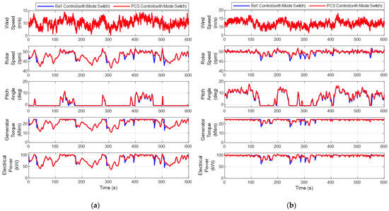
Figure 7.
Comparison of the performance between the reference power control and power control considering the independent generator torque control. (a) Simulation results under an average wind speed of 10 m/s; (b) Simulation results under an average wind speed of 12 m/s.
When applying the PCS torque control, variable generator torque occurs in Region III because the torque command in the PCS is calculated based on the generator speed. In contrast, the reference power control methods utilize the PLC to provide a fixed torque command, whereas the PCS torque control inherently cannot maintain a constant torque. This introduces the additional challenge of being unable to utilize the reference power control methods. Despite these limitations, the PCS torque control has been adopted as the control method for the target wind turbine system to reduce manufacturing and development costs. The performance of the control algorithm, considering this specific scenario, has been validated through simulations.
Table 3 and Table 4 present the quantitative values of the rotor speed and generator power based on the simulation results. For the rotor speed, a tendency toward a relative decrease in standard deviation values compared to the reference power control was observed, with reductions of approximately 2.67% under 10 m/s conditions and about 24.55% under 12 m/s conditions. In the case of the generator power, the impact of the reduced standard deviation of rotor speed led to a decrease of 4.46% under 10 m/s conditions and about 13.99% under 12 m/s conditions. Furthermore, it was determined that the variability in the generator torque command resulting from the PCS torque control system, as opposed to a constant value in the reference power control, contributes to oscillations in the generator power, indicating a limitation of the PCS torque control system.
Table 3.
Comparison of the rotor speed based on the simulation results.
Table 4.
Comparison of the generator power based on the simulation results.
In addition, to verify the performance of the power control with the applied control switching logic, the simulation results under the conditions of average wind speeds of 10 m/s and 12 m/s, and turbulence intensity according to the normal turbulence model Class C, were compared. Figure 8 shows the simulation results of the power control considering the PCS independent generator torque control designed in this study, with mode switch and SPS applied to each algorithm, illustrating the rotor speed, pitch angle, generator torque, generator power, and the fore-aft bending moment at the tower bottom. Figure 8a presents the simulation results under the condition of an average wind speed of 10 m/s, while Figure 8b shows the results under an average wind speed of 12 m/s. Although the time-series data suggest similar performance, it can be observed that the peak values of the rotor speed are reduced due to the operation of the pitch actuator. This can be quantitatively confirmed through the comparison of the Design Equivalent Load (DEL) acting on the fore-aft bending moment at the tower bottom, and Table 5 presents the DEL values of the fore-aft bending moment at the tower bottom based on the simulation results.
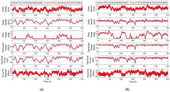
Figure 8.
Performance comparison of the power control considering the mode switch and Set Point Smoother in the independent generator torque control. (a) Simulation results under average wind speed conditions of 10 m/s; (b) Simulation results under average wind speed conditions of 12 m/s.
Table 5.
Comparison of the fore-aft bending moment at the tower (bottom) based on the simulation results.
4. Experimental Validation
To experimentally validate the proposed power control, wind tunnel tests were conducted. The wind tunnel experiments utilized a scaled wind turbine with a rated power of 39.7 W, which was designed and developed through previous research [30]. The blades, hub, tower, and other components of the scaled wind turbine model used in this study were manufactured in South Korea [31]. The wind turbine model features three blades and has a mechanism similar to that of conventional large wind turbines. Considering the operating mechanism akin to that of large wind turbines, the scaled wind turbine model was deemed suitable for experimentally validating the proposed control algorithm. Figure 9 shows the shape of the scaled wind turbine, while Table 6 presents a summary of its specifications.
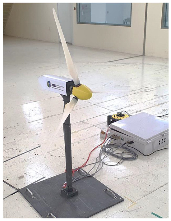
Figure 9.
Scaled wind turbine for the wind tunnel test.
Table 6.
Specification of the scaled wind turbine.
In this study, to accommodate the PCS torque control, the control system was separated to allow for the independent calculation of torque commands based on the generator speed.
4.1. Environment of Wind Tunnel Test
The wind tunnel tests were conducted at the wind tunnel center located at Jeonbuk National University in South Korea. Figure 10 illustrates the experimental setup and the wind turbine testing environment for the target wind tunnel experiment. The wind generation space created by the wind generation device has a length of approximately 40 m in the wind direction and about 12 m in the vertical direction of the wind. The proposed control algorithm was designed to have the same structure as the scaled wind turbine model and was uploaded via commercial PLC programming. Additionally, the setup was configured to allow for data verification and storage through remote monitoring.
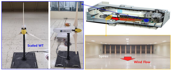
Figure 10.
Experimental environment of the wind tunnel center.
4.2. Simulation Result for Scaled WT
The control algorithm design described earlier has been completed for the scaled wind turbine model using Matlab/Simulink and finalized in DLL format. The external controller in DLL format was integrated with the Bladed software for elastic analysis to conduct dynamic simulations for the performance verification. The simulation conditions included an average wind speed of 6 m/s and a turbulence intensity of approximately 10%, and each algorithm was executed for a duration of 60 s.
Figure 11 shows the simulation results for the reference power control, PCS torque control, and control switching logic control. Similarly, it can be observed that the generator torque value is predominantly influenced by the rotor speed due to the consideration of the PCS torque control. The proposed control algorithm alleviated the sharp drop in the generator torque observed in the reference power control. However, while the reference power control maintains the generator torque value consistently at the rated value in Region III, the PCS torque control exhibits variable values depending on the rotor speed. This has resulted in an increase in the standard deviation of both the generator torque and the power.
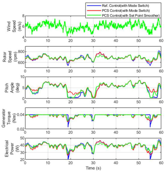
Figure 11.
Comparison of the simulation results for the scaled wind turbine (6 m/s).
Table 7 and Table 8 present the quantitative values of the rotor speed and generator power based on the simulation results. In the case of the rotor speed, a tendency for the standard deviation to decrease relative to the reference power control was observed, with a reduction of approximately 17.73% under the PCS torque control conditions and about 29.58% under the modified control switching logic conditions. For the generator power, an increase of 3.21% was noted under the PCS torque control conditions due to the oscillation of the generator torque, which was analyzed to result from the generator torque command being output as a variable value rather than a constant value, unlike in the reference power control. In contrast, under the modified control switching logic conditions, the generator power decreased by approximately 13.33%, attributed to the alleviation of the rotor speed spikes due to the application of the control switching logic.
Table 7.
Comparison of the rotor speed based on the simulation results (scaled wind turbine).
Table 8.
Comparison of the generator power based on the simulation results (scaled wind turbine).
4.3. Wind Tunnel Test Result
The control algorithm used in the simulation was converted into C (programming language)-based code and updated to the PLC for application to the scaled wind turbine. The average wind speed was set to approximately 5.1 m/s, and the turbulence intensity was set to about 10%. Considering the characteristics of the wind tunnel test, which does not allow for the generation of identical wind conditions, all of the experimental environments, except for the control algorithm, were setup identically for the experiments. Figure 12 shows part of the experimental results obtained from the wind tunnel tests, including the wind speed, rotor speed, blade pitch angle, generator torque, and generator power.
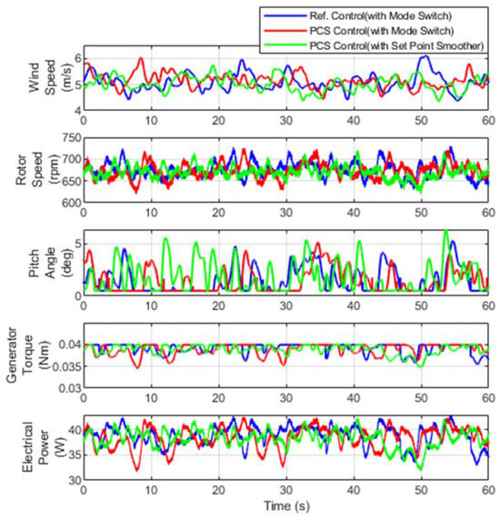
Figure 12.
Comparison of the wind tunnel test results for the scaled wind turbine.
Table 9 and Table 10 show the quantitative values of the rotor speed and generator power based on the results of the wind tunnel tests. In terms of the rotor speed, a similar trend to the simulation was observed, with a relative decrease in the standard deviation compared to the reference power control; specifically, a reduction of approximately 3.60% under the PCS torque control condition and about 21.55% under the modified control switching logic condition. For the generator power, a tendency for a 6.15% increase was noted under the PCS torque control condition due to oscillations in the generator torque. Conversely, under the modified control switching logic condition, the generator power decreased by about 10.77%. While all of the comparisons yielded different absolute values, they exhibited similar trends to those observed in the simulations.
Table 9.
Comparison of the rotor speed based on the wind tunnel test results.
Table 10.
Comparison of the generator power based on the wind tunnel test results.
5. Conclusions
A power control algorithm that takes into account the unique characteristics of a medium-sized wind turbine having a sensorless generator speed estimation method and independent generator torque control in the PCS was designed and validated in the study. The performance verification was conducted through simulations using an aeroelastic analysis program (Bladed) for a 100 kW wind turbine and wind tunnel tests using a scaled wind turbine model.
According to the simulation results for the 100 kW wind turbine, the PCS torque control showed a tendency to reduce the standard deviation of the rotor speed by up to 24.55% and the standard deviation of the generator output by 13.99% compared to the reference power control under the same conditions. However, it was found that, in the Region III operating zone, the generator torque, which varies with the generator speed, can slightly increase the oscillations in the generator power, highlighting a limitation. Additionally, to improve the existing control transition logic, a control transition algorithm incorporating the PCS torque control was applied. The results showed that the DEL and the maximum value of the tower fore-aft bending moment decreased under the same conditions. Specifically, the DEL decreased by approximately 6.11%, and the maximum value decreased by around 11.75%.
Additionally, to experimentally validate the control algorithm, a control algorithm with the same structure was designed for the scaled wind turbine model, and wind tunnel tests were conducted. According to the wind tunnel test results, the PCS torque control reduced the standard deviation of the rotor speed by approximately 3.60%, while the standard deviation of the generator power increased by around 6.15% compared to the reference power control. After applying the control transition logic algorithm to improve this limitation, the standard deviation of the rotor speed decreased by about 21.55%, and the standard deviation of the generator power decreased by approximately 10.77%. This trend was found to be similar to the simulation results.
As a future work, the proposed control algorithm will be applied to the 100 kW wind turbine for experimental validation. Additionally, further development of control algorithms aiming at minimizing power fluctuations and improving the control performance of the target medium-sized wind turbine will be performed.
The proposed control algorithm was specially designed for a medium-size wind turbine having unique characteristics of sensorless generator speed estimation and independent generator torque control in the PCS. Therefore, it is not applicable to conventional large-scaled wind turbines having both generator torque control and blade pitch control in the PLC.
Author Contributions
Conceptualization, D.K.; Methodology, D.K.; Software, D.K. and M.-W.H.; Supervision, I.P.; Validation, D.K. and M.-W.H.; investigation, D.K., W.R. and A.A.; data curation, D.K.; Writing—original draft, D.K.; Writing—review and editing, I.P. All authors have read and agreed to the published version of the manuscript.
Funding
This work was supported by the International Energy Joint R&D Program of the Korea Institute of Energy Technology Evaluation and Planning (KETEP), and granted financial resources from the Ministry of Trade, Industry and Energy, Republic of Korea (No. 20218520020010).
Institutional Review Board Statement
Not applicable.
Informed Consent Statement
Not applicable.
Data Availability Statement
The original contributions presented in the study are included in the article.
Conflicts of Interest
The authors declare no conflicts of interest.
Abbreviations
| Nomenclature | |
| CMD | Command |
| DEL | Design Equivalent Load |
| Diff. | Difference |
| DLL | Dynamic Link Library |
| HAWT | Horizontal axis wind turbine |
| Mode SW | Mode switch |
| PCS | Power Conversion System |
| PI | Proportional–Integral |
| PID | Proportional–Integral–Derivative |
| PLC | Programmable Logic Controller |
| Ref. | Reference |
| SPS | Set Point Smoother |
| VSVP | Variable speed–variable pitch |
| Symbols | |
| Electrical power | |
| Torque command | |
| Generator torque | |
| Rated generator torque | |
| Blade pitch I gain | |
| Blade pitch P gain | |
| Set Point Smoother gain | |
| Pitch angle | |
| Pitch command | |
| Fine pitch angle | |
| Generator speed | |
| Change in generator speed | |
| Rated generator speed | |
| Error in generator speed | |
| Time constant | |
References
- Höffer, R.; Kurniawati, I.; Lupi, F.; Seidel, M.; Niemann, H.J. Full-scale tests on wind turbine towers: Towards a realistic prediction of vortex-induced vibrations. In Proceedings of the 97th CICIND Conference, Paphos, Cyprus, 20–22 October 2022. [Google Scholar]
- Siemens Gamesa. SG 14-222 DD: The Winds of Change Have Never Been Stronger. Available online: https://www.siemensgamesa.com/products-and-services/offshore/wind-turbine-sg-14-222-dd (accessed on 14 October 2024).
- Vestas. V236-15.0 MW. Available online: https://www.vestas.com/en/energy-solutions/offshore-wind-turbines/V236-15MW (accessed on 14 October 2024).
- Żołądek, M.; Figaj, R.; Kafetzis, A.; Panopoulos, K. Energy-economic assessment of self-sufficient microgrid based on wind turbine, photovoltaic field, wood gasifier, battery, and hydrogen energy storage. Int. J. Hydrogen Energy 2024, 52, 728–744. [Google Scholar] [CrossRef]
- Wang, Y.; Wang, Z.; Sheng, H. Optimizing wind turbine integration in microgrids through enhanced multi-control of energy storage and micro-resources for enhanced stability. J. Clean. Prod. 2023, 444, 140965. [Google Scholar] [CrossRef]
- Yan, C.; Zou, Y.; Wu, Z.; Maleki, A. Effect of Various Design Configurations and Operating Conditions for Optimization of a Wind/Solar/Hydrogen/Fuel Cell Hybrid Microgrid System by a Bio-Inspired Algorithm. Int. J. Hydrogen Energy 2024, 60, 378–391. [Google Scholar] [CrossRef]
- Tzen, E. Small Wind Turbines for on Grid and off Grid Applications. IOP Conf. Ser. Earth Environ. Sci. 2020, 410, 012047. [Google Scholar] [CrossRef]
- Tummala, A.; Velamati, R.K.; Sinha, D.K.; Indraja, V.; Krishna, V.H. A review on small scale wind turbines. Renew. Sustain. Energy Rev. 2016, 56, 1351–1371. [Google Scholar] [CrossRef]
- Bianchini, A.; Bangga, G.; Baring-Gould, I.; Croce, A.; Cruz, J.I.; Damiani, R.; Erfort, G.; Simao Ferreira, C.; Infield, D.; Nayeri, C.N.; et al. Current status and grand challenges for small wind turbine technology. Wind Energy Sci. 2022, 7, 2003–2037. [Google Scholar] [CrossRef]
- Gözcü, O.; Kim, T.; Verelst, D.R.; McWilliam, M.K. Swept Blade Dynamic Investigations for a 100 kW Small Wind Turbine. Energies 2022, 15, 3005. [Google Scholar] [CrossRef]
- Lin, Y.T.; Chiu, P.H.; Huang, C.C. An experimental and numerical investigation on the power performance of 150 kW horizontal axis wind turbine. Renew. Energy 2017, 113, 85–93. [Google Scholar] [CrossRef]
- Bossanyi, E.A. The design of closed loop controllers for wind turbines. Wind Energy Int. J. Prog. Appl. Wind Power Convers. Technol. 2000, 3, 149–163. [Google Scholar]
- Nam, Y. Wind Turbine System Control, 1st ed.; GS Intervision: Seoul, Republic of Korea, 2013. [Google Scholar]
- Bossanyi, E.A. Wind turbine control for load reduction. Wind Energy 2003, 6, 229–244. [Google Scholar] [CrossRef]
- Mandic, G.; Nasiri, A.; Muljadi, E.; Oyague, F. Active Torque Control for Gearbox Load Reduction in a Variable-Speed Wind Turbine. IEEE Trans. Ind. Appl. 2012, 48, 2424–2432. [Google Scholar] [CrossRef]
- Brandetti, L.; Mulders, S.P.; Liu, Y.; Watson, S.; van Wingerden, J.-W. Analysis and multi-objective optimisation of wind turbine torque control strategies. Wind Energy Sci. 2023, 8, 1553–1573. [Google Scholar] [CrossRef]
- Barambones, O.; Cortajarena, J.; Calvo, I.; de Durana, J.G.; Alkorta, P.; Karami-Mollaee, A. Variable speed wind turbine control scheme using a robust wind torque estimation. Renew. Energy 2019, 133, 354–366. [Google Scholar] [CrossRef]
- Tian, D.; Tang, S.; Tao, L.; Li, B.; Wu, X. Peak shaving strategy for load reduction of wind turbines based on model predictive control. Energy Rep. 2023, 9, 338–349. [Google Scholar] [CrossRef]
- Kim, K.; Kim, H.-G.; Paek, I. Application and Validation of Peak Shaving to Improve Performance of a 100 KW Wind Turbine. Int. J. Precis. Eng. Manuf.-Green Technol. 2020, 7, 411–421. [Google Scholar] [CrossRef]
- Bao, J.; Yue, H.; Leithead, W.E.; Wang, J.Q. Feedforward Control for Wind Turbine Load Reduction with Pseudo-LIDAR Measurement. Int. J. Autom. Comput. 2018, 15, 142–155. [Google Scholar] [CrossRef]
- Bossanyi, E. Individual blade pitch control for load reduction. Wind Energy 2003, 6, 119–128. [Google Scholar] [CrossRef]
- Petrović, V.; Jelavić, M.; Baotić, M. MPC framework for constrained wind turbine individual pitch control. Wind Energy 2021, 24, 54–68. [Google Scholar] [CrossRef]
- Dickler, S.; Kallen, T.; Zierath, J.; Abel, D. Rapid control prototyping of model predictive wind turbine control toward field testing. J. Phys. Conf. Ser. 2020, 1618, 022068. [Google Scholar] [CrossRef]
- Tang, X.; Yin, M.; Shen, C.; Xu, Y.; Dong, Z.Y.; Zou, Y. Active Power Control of Wind Turbine Generators via Coordinated Rotor Speed and Pitch Angle Regulation. IEEE Trans. Sustain. Energy 2018, 10, 822–832. [Google Scholar] [CrossRef]
- Henz, G.; Koch, G.; Franchi, C.M.; Pinheiro, H. Development of a variable speed wind turbine emulator for research and training. In Proceedings of the 2013 Brazilian Power Electronics Conference, Gramado, Brazil, 27–31 October 2013; pp. 737–742. [Google Scholar]
- Pena, R.; Clare, J.; Asher, G. A doubly fed induction generator using back-to-back PWM converters supplying an isolated load from a variable speed wind turbine. IEEE Proc.-Electr. Power Appl. 1996, 143, 380–387. [Google Scholar] [CrossRef]
- Song, S.-H.; Kang, S.-I.; Hahm, N.-K. Implementation and control of grid connected AC-DC-AC power converter for variable speed wind energy conversion system. In Proceedings of the Eighteenth Annual IEEE Applied Power Electronics Conference and Exposition (APEC’03), Miami Beach, FL, USA, 9–13 February 2003; IEEE: Piscataway Township, NJ, USA, 2012; pp. 154–158. [Google Scholar]
- Kim, K.; Kim, H.; Paek, I.; Kim, H.; Son, J. Field Validation of Demanded Power Point Tracking Control Algorithm for Medium-Capacity Wind Turbine. Int. J. Precis. Eng. Manuf.-Green Technol. 2019, 6, 875–881. [Google Scholar] [CrossRef]
- Abbas, N.; Zalkind, D.; Pao, L.; Wright, A. A Reference Open-Source Controller for Fixed and Floating Offshore Wind Turbines. Wind Energy Sci. 2022, 7, 53–73. Available online: https://wes.copernicus.org/articles/7/53/2022/ (accessed on 14 October 2024). [CrossRef]
- Campagnolo, F. Wind Tunnel Testing of Scaled Wind Turbine Models: Aerodynamics and Beyond. Ph.D. Thesis, Politecnico Di Milano, Milan, Italy, 2013. [Google Scholar]
- Kim, D.; Paek, I.; Won, B.; Jeon, T. Performance Test of 3D Printed Blades for a Scaled Wind Turbine in a Wind Tunnel. J. Korean Soc. Precis Eng. 2020, 37, 707–715. [Google Scholar] [CrossRef]
Disclaimer/Publisher’s Note: The statements, opinions and data contained in all publications are solely those of the individual author(s) and contributor(s) and not of MDPI and/or the editor(s). MDPI and/or the editor(s) disclaim responsibility for any injury to people or property resulting from any ideas, methods, instructions or products referred to in the content. |
© 2024 by the authors. Licensee MDPI, Basel, Switzerland. This article is an open access article distributed under the terms and conditions of the Creative Commons Attribution (CC BY) license (https://creativecommons.org/licenses/by/4.0/).