Abstract
This paper addresses the robust control for a slung-mass quadrotor under abrupt velocity changes. The proposed algorithm is based on a sliding mode controller applied to the quadrotor translational dynamics considering the slung-mass angle as feedback. A Lyapunov candidate function is used to demonstrate system stability. Numerical simulations are performed to demonstrate stability in hover, forward flight, and under abrupt velocity changes. Experimental tests show that the proposed approach is also robust for stabilizing the aerial vehicle against disturbances caused by slung-load oscillations and wind gusts in outdoor environments by stopping the forward velocity from 29 km/h to hover by compensating within 1 s for the slung-mass oscillations.
1. Introduction
Many important practical situations require rapid deployment of Unmanned Aerial Vehicles (UAVs) for delivery of cargo, for example immediately after a natural disaster or an industrial accident, since these emergency situations require faster delivery times compared to traditional methods [1,2]. In [3] the authors set the stage for the delivery of first aid kits to people lost in a forest, which is an environment crowded with vertical obstacles, such as the tree trunks. The use of a quadrotor aircraft is proposed, which must make the delivery of the package by overcoming the obstacles. In this case, experimental tests were performed in a controlled environment using a Motion Capture (MoCap) system, obtaining good results. Despite the wide range of applications, the transport of loads with quadrotors still represents an important challenge, since these aerial vehicles are by themselves multivariable systems, subactuated, highly nonlinear, and when adding the load its dynamics becomes even more complex [4,5,6]. To deal with this problem different solutions have been proposed whose main objective is to reduce the slung-mass oscillations that negatively impact the quadrotor’s flight stability. One of those solutions is the use of multi-agents for cooperative load transport proposed by the authors in [7,8,9,10] using two quadrotors while in [11] the use of three or more aerial vehicles is proposed in [12]. Although it has been shown that the use of multiple robots in cooperative tasks increases robustness against external disturbances, it also results in a system too expensive for small loads. Therefore, the most popular solution is the use of a single quadrotor UAV for transporting loads [13,14,15,16]. In [17] the authors present a set of several suspended load methods using a UAV or a swarm of UAVs. However, these strategies are only implemented in a numerical simulation without checking their performance in real-time to observe the possible effect that the suspended load could have in outdoor environments. There exist two main proposals for the fastening the load: cable transport and handling with robotic arms. These methods have advantages and disadvantages: the robotic arm is more practical for gripping and releasing cargo, yet it adds extra weight to the aircraft, is expensive, and consumes a considerable amount of energy. The use of the cable does not have these disadvantages, which is why in this work this method is used for the transport of load with a quadrotor aircraft. As mentioned above, many works use a cable to transport a suspended load with a quadrotor due to its low cost and weight. However, the oscillations produced by the load represent a problem because they affect the performance of the flight of the aircraft, compromising its stability and trajectory [18]. Baraean et al. [19] developed a controller using the backstepping approach and Lyapunov theory to solve the tracking problem of a cable-suspended mass. Although the results confirm the effectiveness of the controller, only simulation tests are presented. Zare et al. [20] proposed an optimized sliding mode control through an intelligent fuzzy genetic algorithm; their simulation results corroborate the robustness of the proposed method. El et al. [21] developed a robust Fractional-Order Sliding Mode Control (FOSMC) to control the altitude, position and attitude of the quadrotor. A delayed feedback based anti-swing controller was also installed to limit the swing angle of the suspended load. MATLAB SIMULINK software was used to test and simulate the suggested controller. Bingöl et al. [22] designed a Finite-Time Neuro-Sliding Mode Controller (FTNSMC) for a quadrotor with a suspended payload that is subject to parametric uncertainties and external disturbances. Numerical simulations to demonstrate the effectiveness of the proposed controller were presented.
In [23] the authors also developed a backstepping controller using Lyapunov theory for a quadrotor with a slung-mass system that drives the mass angular position to a desired trajectory. However, they check the controller’s performance experimentally in a controlled environment using a VICON MoCap system. To ensure the stability of a quadrotor with suspended load, Ding et al. [24] developed a Lyapunov-based control strategy to satisfy the restrictions on the load oscillation angles. Furthermore, the authors demonstrated in numerical results that the proposed control guarantees the restrictions on the rotation angle of the payload and also reduces energy consumption. Shi et al. [25] considered the torque generated by the suspended load as a disturbance that directly affects the stability of the aircraft. Therefore, they proposed an algorithm based on an extended harmonic state observer to compensate the induced torque. Other works consider more challenging scenarios, Dalwadi et al. [26] present a nonlinear observer-based backstepping controller that can compensate the slung-load disturbances, partial rotor failures, and wind gusts. They validated their proposal through numerical simulation. Yi et al. [27] present a simple control scheme based on the active compensation of sudden load changes, rejecting disturbances and preserving the controller characteristics and parameters. They validated their experimental scheme in a controlled environment using the Qualisys MoCap system. There are some cases in which the load mass is unknown such as in packages delivery, and to deal with this problem different solutions are proposed. Yu et al. [28] propose nonlinear control algorithms for the thrust and the angular velocity of the quadrotor, and a mass estimation algorithm. These control laws are robust to variations of the load mass and ensure trajectory tracking convergence. They validated their results through numerical simulations and experimentally in a controlled environment using a MoCap system. Kong et al. [29] propose an adaptive control law designed in the framework of backstepping to estimate the unknown load mass and compensate disturbances caused by the slung-loading subsystem.
Many studies focus on controlling or reducing load oscillations during transportation by implementing various robust nonlinear and model-based controllers [30,31,32]. For example, in [33], the authors emphasize the importance of mitigating suspended load oscillations, as they affect quadrotor performance. The study analyzes the modeling and control of a quadrotor with a suspended load using sliding mode control, with simulations demonstrating the effectiveness of the proposed control strategy. Aldhizer et al. [34], develop an algorithm that reduces the swing angle of a person suspended under a helicopter by adjusting the cable length during movement. Peris et al. [35] combine multiple surface sliding control (MSSC), radial basis function neural networks (RBFNN), and deep reinforcement learning (DQN) to stabilize trajectory tracking and suppress oscillations of the suspended load. The present work aims not only to reduce the oscillations of a suspended mass in a quadrotor but also to stabilize it in response to abrupt speed changes.
Contributions
- This paper presents a robust control law to reduce oscillations caused by a slung load on a quadrotor and to stabilize a slung load in abrupt velocity changes.
- The robust technique is based on a sliding mode controller that compensates for disturbances associated with the trajectory that the vehicle follows to carry the load from one location to another.
- The main characteristic of this algorithm is to obtain the slung-mass angular position and velocity measurements (, ) to provide feedback and achieve its stabilization on the vertical axis in order to improve the performance by reducing the oscillations in outdoor real-time experiments.
The present paper is organized as follows: Section 2 presents the system modeling and robust control design, which includes the modeling of the slung-mass quadcopter and design of robust control laws for vertical and longitudinal dynamics. The experimental setup is described in Section 3. Section 4 and Section 5 contains the simulation and the experimental results, respectively. Finally, in Section 6 the conclusions are presented.
2. System Modeling and Robust Control Design
2.1. Slung-Mass Quadrotor Modeling
The slung-mass quadrotor dynamical model and the design of the robust control algorithm are presented in this section. In order to simplify the dynamical model, the following hypothesis are assumed:
- The air vehicle is considered as a rigid body.
- The load is rigid and its mass is constant.
- The mass is suspended under the vehicle by a rigid rod.
- The slung-mass angular position is bounded.
- The suspended mass does not rotate on its azimuthal axis.
In the same way, the control algorithm is designed to be robust against the following:
- External disturbances such as wind and gust.
- Disturbances caused by slung-mass oscillations.
- Uncertainties not modeled in the system.
The generalized coordinates of the aircraft system are where the translational and rotational coordinates are and , respectively. Figure 1 depicts the quadrotor with slung-load diagram, where represents the i-rotor force where . k represents a set of the aerodynamic constants, d is the distance from the rotors to the center of the mass and the angular velocity is represented by . The inertial frame represents the longitudinal, lateral, and vertical axes, is the body fixed coordinate frame. M represents the quadrotor mass and m the slung-load mass, l is the distance from the center of the mass to the slung mass, g is the acceleration due gravity, and are the angular position of the slung mass in the longitudinal and lateral axes, respectively.
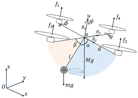
Figure 1.
Slung-mass quadrotor diagram.
The total thrust is defined as ) and the rotor torque is defined as follows:
where is the torque produced by each rotor. Therefore, according to [36] the equations of motion for the quadrotor with slung mass are as follows:
where , , , are defined as follows
with
where is the rotational matrix from the body frame to the inertial frame with
2.2. Longitudinal Dynamics Modeling
The goal of the control design is to dampen oscillations of the slung mass when the velocity changes abruptly. The quadrotor displacement on the y-axis is neglected due to the quadrotor navigation being always in forward direction. The slung mass is connected to the aircraft through a bar and the angle of the slung mass is locked by a bearing which only allows oscillations at angle. It is assumed that the velocity abrupt change forward navigation of the quadcopter induces oscillations on the angular position of the slung mass. These oscillations could cause catastrophic scenarios. Reduction in the overall dynamic model to a longitudinal dynamics is possible by considering only the forward navigation and using a bearing for locking the angle of the bar. Thus, the planar mathematical model contains only the longitudinal and vertical displacements x and z, angular displacement and the angular position of the slung-mass . Then, the longitudinal model is expressed as follows:
where for are perturbations due to wind, gust, etc. The natural behavior of the is oscillatory and depends on the initial conditions (small angle):
2.3. Vertical Robust Control Design ()
The vertical robust control is proposed considering , the vertical thrust force u is proposed as follows:
where is defined later, introducing (4) into (2b) it follows that
The following expression is defined:
where is a constant. Then, the time-derivative is obtained as follows:
Proposing the following function
and its derivative is obtained as follows:
considering the following hypothesis 1: is defined as . Then, the following sliding mode control is proposed.
then
where . The approximation is implemented
then, after a finite time
2.4. Longitudinal Robust Control Design ()
After a finite time from (2a):
Proposing the following robust torque control for the attitude
where . After a finite time and from (2d) converges to .
By choosing where is defined latter, then
where is the virtual control input of x dynamics. Considering the following hypothesis 2: , and . The following expression is proposed:
Then, the derivative is obtained as follows:
Let us propose the following positive function:
and its derivative is obtained as follows:
The proposed attitude control algorithm is given by
then
where , then
after a finite time .
The longitudinal error is defined as follows:
then, so exponentially. Define the desired longitudinal position as follows:
where a is the constant velocity desired displacement. From the above it follows that
Finally, after a certain time hence .
So that after a time , from Equation (2c) and applying the sliding mode control then z-dynamics converges, so , and converges to zero in finite time.
angle is bounded by the mechanical constraints to .
Proposing the following positive function:
Then, using (2c)
According with the LaSalle’s theorem then . From (2c), , then so the origin is asymptotically stable.
When the angle is small the —dynamics becomes
which is a stable dynamic for angle and converges to zero asymptotically.
3. Numerical Simulations
This section presents the results of the numerical simulation obtained from applying the robust control algorithm to the dynamical model of the quadrotor with slung mass in hover and in abrupt changes in velocity navigation. The altitude z is controlled by using u as control input (4). The longitudinal and attitude displacement x is controlled using the input control given in (15) and (21). The approximation is implemented to avoid the chattering effect during simulations and experiments. Numerical simulations are run with different initial conditions and adding Gaussian white noise with mean 0 and variance in the inputs. Figure 2 and Figure 3 present the results for initial conditions mentioned in Table 1. Controller parameters are adjusted considering a fast an under damped transitory response for simulation. Real-time experiments the control parameters are tuned follows the simulations’ parameters and after a little bit they are adjusted considering the atmospheric conditions.
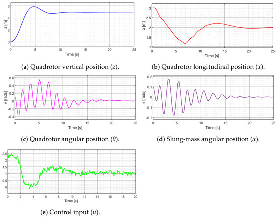
Figure 2.
Hover flight simulation results.
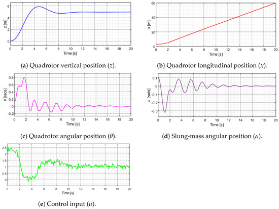
Figure 3.
Forward navigation simulation data.

Table 1.
Slung-mass quadrotor simulation parameters.
3.1. Hover Flight
Figure 2 shows the simulation results applying the control algorithms to the dynamic model of the slung-mass quadcopter starting from an initial position, then reaching a desired position after a while and finally remaining in hover. The altitude performance is shown in Figure 2a. Figure 2b presents the longitudinal position x with initial condition in 3 m and 2 m as a reference. The pitch angular position of the quadrotor is showed in Figure 2c with rad as initial condition. Finally, Figure 2d depicts the slung-mass angular position with initial condition of rad. Figure 2e shows the control input u applied to the hover flight simulation. The angular position of the quadcopter and slung-mass angular position reduce oscillations until they converge to almost zero.
3.2. Forward Navigation
Figure 3 shows the simulation results of the quadrotor and the slung mass applying the control algorithms in forward navigation. The altitude performance is shown in Figure 3a. Figure 3b presents the longitudinal position x with initial condition in 3 m. The pitch angular position of the quadrotor is showed in Figure 3c with rad as initial condition. Finally, Figure 3d depicts the slung-mass angular position with initial condition of rad. Figure 3e shows the control input u applied to the forward flight simulation. In this case, the performance of the simulations are similar to the hover flight simulations.
3.3. Abrupt Changes in Velocity
A sawtooth signal was proposed as a velocity reference (see Figure 4a). This reference signal reaches 8 m/s in 5 s and later changes to 0 m/s, oscillations appears in the slung mass. Applying angle feedback, the oscillations are reduced in a bounded small region shown in Figure 4b. Figure 4c shows the slung-mass behavior without considering the feedback.
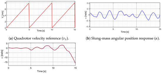
Figure 4.
Abrupt changes in velocity simulation data.
3.4. Comparative Result
In [37], the authors proposed a robust observer and they considered the oscillation like a perturbations. They propose the following input control:
where is the sliding surface, is the longitudinal error, and are positive gains. Figure 5 shows the angle overshot and the simulation fails when the velocity reference changes abruptly with a sawtooth velocity input. As shown in Figure 4c, the response of the closed-loop system without considering feedback shows the oscillations increasing quickly; this phenomena is observed in this comparative result, in this case the oscillations increased abruptly in a short time.
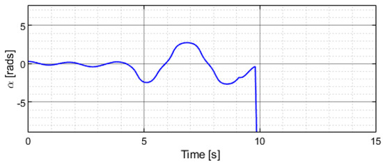
Figure 5.
Simulation result of the slung-mass angular position ().
4. Experimental Setup
This section presents the experimental setup used to perform outdoor flight tests. The experimental platform is shown in Figure 6. The slung mass is attached to the quadrotor with a rigid rod at 20 cm below the airframe.
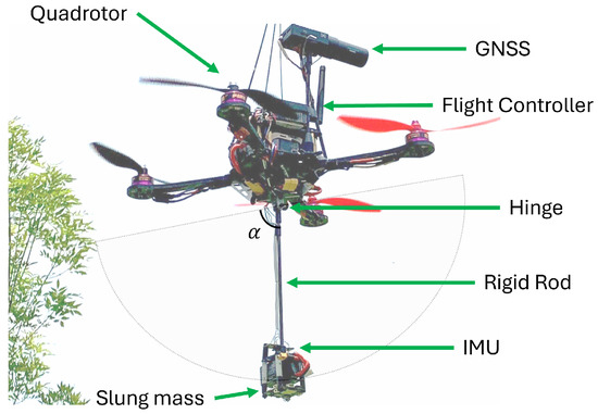
Figure 6.
Experimental setup.
The slung-mass -angle has been mechanically locked, hence it can only balance the angle and a bearing is used to reduce friction on the hinge. Furthermore, the slung mass cannot rotate about the yaw moment axis of the rigid rod. An external IMU attached to the slung mass is used to measure the angular position and velocity (). These measurements are transmitted to the autopilot through the Inter Integrated Circuit (I2C) communication interface. Robust control algorithms are implemented on a CubePilot Cube Orange+ flight controller PX4 Firmware compatible. The autopilot has triple redundancy IMU’s for attitude measurements (accelerometer, gyroscope, and compass). Real-Time Kinematic (RTK) positioning data are obtained by a Global Navigation Satellite System (GNSS) and a differential ground station reference for centimeter accuracy.
Figure 7 illustrates the outdoor flight test of the quadcopter in forward navigation tracking a speed reference. Table 2 lists the environmental conditions during the outdoor experimental tests. It can be observed that the angular position of the suspended mass is opposite to the direction of travel of the quadrotor.
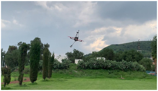
Figure 7.
Quadrotor with slung-mass outdoor flight test.
Table 2.
Environmental conditions during outdoor experimental test.
5. Experimental Results
In order to verify the proposed control strategy in real-time, experimental tests were realized to show the performance in outdoor environments. One of the challenges in the transport of suspended loads is the strong induced disturbance when abrupt changes occur in translational velocities. The slung-mass oscillatory behavior has been shown in both numerical simulations and experimental tests. The slung-load position and velocity angle could be used to reduce the oscillations. From the simulation results the slung-mass oscillations presented in the three cases are worst under abrupt velocity changes. Due to these considerations, the experimental results were conducted only considering abrupt velocity changes.
The velocity reference is similar to the sine function but creates a sawtooth wave with peaks of 0 and 8 m/s, this function was programmed on the quadcopter autopilot increasing the forward speed and then returning to hover flight. This forward and stop routine is repeated in the quadrotor flight. The forward navigation velocity of the slung-mass quadrotor and the slung-mass angular position response during the outdoor flight tests are shown as follows:
5.1. Control Without Angle Feedback
The first test was achieved without angle feedback, the increase and decrease in the forward navigation velocity (see Figure 8a) of the quadcopter induces an unwanted oscillatory behavior in the angle of the slung mass as shown in Figure 8b.
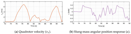
Figure 8.
Real-time experimentation: (a) Quadrotor velocity and (b) slung-mass angle response without feedback.
5.2. Control with Angle Feedback
The second test was achieved considering angle feedback: the experimentation starts with the quadrotor in hover, from 55 s the forward velocity increases to almost 6 m/s and then decreases to zero, then the quadrotor returns to hover. Oscillations damped can be observed in the flight test, see Figure 9b. At 63 s the test is repeated until reaching 7 m/s, as shown in Figure 9a.
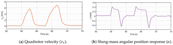
Figure 9.
Real-time experimentation of the (a) quadrotor velocity and (b) slung-mass angle response with feedback.
The dynamic model (2c) used in the simulations does not take into account the drag forces produced by the wind on the slung mass. These forces actuated as negative feedback in the dynamic model reducing the oscillations, this phenomenon appears in real-time experiments. This behavior can be observed in Figure 8b 75 s and also in Figure 9b 55 s. Without feedback, the oscillations induce perturbations in the velocity of the quadcopter, as shown in Figure 8a.
Figure 10 shows the path followed by the aircraft during the experimental test of the robust control in fast trajectory navigation followed in the experiments, obtained from the GPS signal. It shows the vertical takeoff, the accelerations, and decelerations in the longitudinal trajectory and the vertical landing.
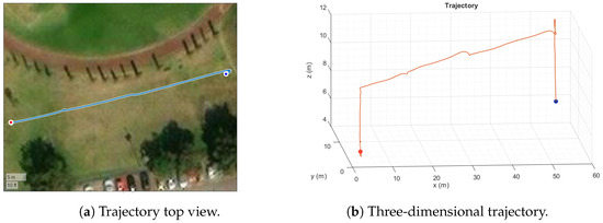
Figure 10.
Slung-mass quadrotor under abrupt velocity changes in outdoor experimentation.
Robust control considers external bounded disturbances and perturbations induced by the suspended load. Failures due to malfunctioning in the GPS signal, communication with the radio control, communication with the ground station or the battery are contemplated in the flight plan to perform an emergency landing. These safety protocols prevent overheating of the engines due to the demands of the control algorithm.
6. Conclusions and Discussion
A control algorithm with robustness with respect to abrupt velocity changes in a quadrotor with slung load is proposed to compensate and reduce oscillations. The full dynamics considering the slung mass is assumed as a subactuated system with two inputs (,u) and four states (x,y,,). The slung mass has a critical stable point and a small perturbation induces an oscillatory behavior. When velocity quadrotor changes in fast navigation maneuvers, particularly in abrupt acceleration and deceleration, the oscillations generated by these behavior could produce catastrophic scenarios. The proposed strategy used a sliding mode approximation on the attitude dynamics. A control input based on a tangent function is used in a translational model in order to compensate the nonlinearities and disturbances.
Angular position and velocity measurements of the load provided by an additional IMU are used as feedback to synchronize the acceleration of the aerial vehicle to damped oscillations. A Lyapunov-based stability analysis is provided for the altitude and the translational dynamics to verify the convergence of the error dynamics in a finite time. Numerical simulations and real-time experiments demonstrated the validity of the proposed robust control algorithm. The stability of the slung-mass dynamics was verified using a Lyapunov function.
In order to validate the control strategy a sawtooth velocity reference was induced to the horizontal displacement, this behavior was performed in real-time experiments, the maximal speed was almost 29 km/h. In the case of angle feedback the oscillations were reduced from 0.4 rads to almost 0 in 1 s.
Author Contributions
Investigation, S.S.; investigation, J.F.; conceptualization, Y.R.-L.; data curation, I.G.-H.; project administration, R.L. All authors have read and agreed to the published version of the manuscript.
Funding
This project was funded by Department of Research and Multidisciplinary Studies of Research and Advanced Studies Center of the National Polytechnic Institute (CINVESTAV-IPN).
Institutional Review Board Statement
Not applicable.
Informed Consent Statement
Not applicable.
Data Availability Statement
Dataset available on request from the authors.
Acknowledgments
The authors are grateful to National Council of Science, Humanities, and Technology (CONAHCYT) for its support.
Conflicts of Interest
The authors declare no conflicts of interest.
Abbreviations
The following abbreviations are used in this manuscript:
| UAV | Unmanned Aerial Vehicle |
| FTNSMC | Finite-Time Neuro-Sliding Mode Control |
| FOSMC | Fractional-Order Sliding Mode Control |
| VTOL | Vertical Take-Off and Landing |
| GPS | Global Positioning System |
| MoCap | Motion Capture |
| IMU | Inertial Measurement Unit |
| I2C | Inter Integrated Circuit |
| RTK | Real-Time Kinematic |
| GNSS | Global Navigation Satellite System |
References
- Mohta, K.; Sun, K.; Liu, S.; Watterson, M.; Pfrommer, B.; Svacha, J.; Mulgaonkar, Y.; Taylor, C.J.; Kumar, V. Experiments in fast, autonomous, gps-denied quadrotor flight. In Proceedings of the 2018 IEEE International Conference on Robotics and Automation (ICRA), Brisbane, Australia, 21–25 May 2018; pp. 7832–7839. [Google Scholar]
- Zhou, B.; Gao, F.; Wang, L.; Liu, C.; Shen, S. Robust and efficient quadrotor trajectory generation for fast autonomous flight. IEEE Robot. Autom. Lett. 2019, 4, 3529–3536. [Google Scholar] [CrossRef]
- Pizetta, I.H.B.; Brandão, A.S.; Sarcinelli-Filho, M. Load Transportation by Quadrotors in Crowded Workspaces. IEEE Access 2020, 8, 223941–223951. [Google Scholar] [CrossRef]
- Us, K.Y.; Cevher, A.; Sever, M.; Kırlı, A. On the Effect of Slung Load on Quadrotor Performance. Procedia Comput. Sci. 2019, 158, 346–354. [Google Scholar] [CrossRef]
- Yang, S.; Xian, B.; Cai, J.; Wang, G. Finite-time convergence control for a quadrotor unmanned aerial vehicle with a slung load. IEEE Trans. Ind. Inform. 2023, 20, 605–614. [Google Scholar] [CrossRef]
- Xian, B.; Wang, S.; Yang, S. An online trajectory planning approach for a quadrotor UAV with a slung payload. IEEE Trans. Ind. Electron. 2019, 67, 6669–6678. [Google Scholar] [CrossRef]
- Ariyibi, S.O.; Tekinalp, O. Quaternion-based nonlinear attitude control of quadrotor formations carrying a slung load. Aerosp. Sci. Technol. 2020, 105, 105995. [Google Scholar] [CrossRef]
- Pizetta, I.H.B.; Brandão, A.S.; Sarcinelli-Filho, M. Avoiding obstacles in cooperative load transportation. ISA Trans. 2019, 91, 253–261. [Google Scholar] [CrossRef]
- Chai, Y.; Liang, X.; Yang, Z.; Han, J. Energy-based nonlinear adaptive control for collaborative transportation systems. Aerosp. Sci. Technol. 2022, 126, 107510. [Google Scholar] [CrossRef]
- Gimenez, J.; Gandolfo, D.C.; Salinas, L.R.; Rosales, C.; Carelli, R. Multi-objective control for cooperative payload transport with rotorcraft UAVs. ISA Trans. 2018, 80, 491–502. [Google Scholar] [CrossRef]
- Mechali, O.; Xu, L.; Xie, X. Formation Flight Control of Networked-Delayed Quadrotors for Cooperative Slung Load Transportation. In Proceedings of the 2022 IEEE International Conference on Mechatronics and Automation (ICMA), Guilin, China, 7–10 August 2022; pp. 526–531. [Google Scholar] [CrossRef]
- Arab, F.; Shirazi, F.A.; Yazdi, M.R.H. Planning and distributed control for cooperative transportation of a non-uniform slung-load by multiple quadrotors. Aerosp. Sci. Technol. 2021, 117, 106917. [Google Scholar] [CrossRef]
- Roy, K.R.; Waghmare, L.M.; Patre, B.M. Dynamic modeling and displacement control for differential flatness of quadrotor UAV slung-load system. Int. J. Dyn. Control 2023, 11, 637–655. [Google Scholar] [CrossRef]
- Reis, J.; Yu, G.; Cabecinhas, D.; Silvestre, C. High-performance quadrotor slung load transportation with damped oscillations. Int. J. Robust Nonlinear Control 2023, 33, 10227–10256. [Google Scholar] [CrossRef]
- Ergezer, H. Multi-objective trajectory planning for slung-load quadrotor system. IEEE Access 2021, 9, 155003–155017. [Google Scholar] [CrossRef]
- Wang, Y.; Yu, G.; Xie, W.; Zhang, W.; Silvestre, C. UDE-based Robust Control of a Quadrotor-Slung-Load System. IEEE Robot. Autom. Lett. 2023, 8, 6851–6858. [Google Scholar] [CrossRef]
- Estévez Sanz, J.; Garate Zubiaurre, G.; López Guede, J.M.; Larrea Sukia, M. Review of Aerial Transportation of Suspended-Cable Payloads with Quadrotors. Drones 2024, 8, 35. [Google Scholar] [CrossRef]
- Feng, Y.; Rabbath, C.A.; Rakheja, S.; Su, C.Y. Adaptive controller design for generic quadrotor aircraft platform subject to slung load. In Proceedings of the 2015 IEEE 28th Canadian Conference on Electrical and Computer Engineering (CCECE), Halifax, NS, Canada, 3–6 May 2015; pp. 1135–1139. [Google Scholar]
- Baraean, A.; Hamanah, W.M.; Bawazir, A.; Quama, M.M.; Ferik, S.E.; Baraean, S.; Abido, M.A. Optimal Nonlinear backstepping controller design of a Quadrotor-Slung load system using particle Swarm Optimization. Alex. Eng. J. 2023, 68, 551–560. [Google Scholar] [CrossRef]
- Zare, M.; Pazooki, F.; Haghighi, S.E. Hybrid controller of Lyapunov-based and nonlinear fuzzy-sliding mode for a quadrotor slung load system. Eng. Sci. Technol. Int. J. 2022, 29, 101038. [Google Scholar] [CrossRef]
- El Ferik, S.; Al-Qahtani, F.M.; Saif, A.W.A.; Al-Dhaifallah, M. Robust FOSMC of quadrotor in the presence of slung load. ISA Trans. 2023, 139, 106–121. [Google Scholar] [CrossRef]
- Bingöl, Ö.; Güzey, H.M. Finite-time neuro-sliding-mode controller design for quadrotor uavs carrying suspended payload. Drones 2022, 6, 311. [Google Scholar] [CrossRef]
- Yu, G.; Cabecinhas, D.; Cunha, R.; Silvestre, C. Nonlinear backstepping control of a quadrotor-slung load system. IEEE/ASME Trans. Mechatron. 2019, 24, 2304–2315. [Google Scholar] [CrossRef]
- Ding, F.; Sun, C.; He, S. Anti-Swing Control for Quadrotor-Slung Load Transportation System with Underactuated State Constraints. Sensors 2023, 23, 8995. [Google Scholar] [CrossRef] [PubMed]
- Shi, D.; Wu, Z.; Chou, W. Harmonic extended state observer based anti-swing attitude control for quadrotor with slung load. Electronics 2018, 7, 83. [Google Scholar] [CrossRef]
- Dalwadi, N.; Deb, D.; Muyeen, S. Observer based rotor failure compensation for biplane quadrotor with slung load. Ain Shams Eng. J. 2022, 13, 101748. [Google Scholar] [CrossRef]
- Yi, K.; Liang, X.; He, Y.; Yang, L.; Han, J. Active-model-based control for the quadrotor carrying a changed slung load. Electronics 2019, 8, 461. [Google Scholar] [CrossRef]
- Yu, G.; Xie, W.; Cabecinhas, D.; Cunha, R.; Silvestre, C. Adaptive control with unknown mass estimation for a quadrotor-slung-load system. ISA Trans. 2023, 133, 412–423. [Google Scholar] [CrossRef]
- Kong, L.; Reis, J.; He, W.; Yu, X.; Silvestre, C. On dynamic performance control for a quadrotor-slung-load system with unknown load mass. Automatica 2024, 162, 111516. [Google Scholar] [CrossRef]
- Sun, H.; Gu, X.; Luo, S.; Liang, Y.; Bai, J. Robust stabilization technique for a quadrotor slung-load system using sliding mode control. J. Phys. Conf. Ser. 2022, 2232, 012013. [Google Scholar] [CrossRef]
- Mosco-Luciano, A.; Castro-Linares, R.; Rodriguez-Cortes, H. Trajectory tracking control for a quadrotor with a slung load. In Proceedings of the 2020 International Conference on Unmanned Aircraft Systems (ICUAS), Athens, Greece, 1–4 September 2020; pp. 322–328. [Google Scholar]
- Ergezer, H.; Leblebicioğlu, K. Control structure design with constraints for a slung load quadrotor system. Meas. Control 2024, 57, 16–29. [Google Scholar] [CrossRef]
- Kui, Y.; Feng, G.; Liying, Y.; Yuqing, H.; Jianda, H. Sliding mode control for a quadrotor slung load system. In Proceedings of the 2017 36th Chinese Control Conference (CCC), Dalian, China, 26–28 July 2017; pp. 3697–3703. [Google Scholar]
- Aldhizer, T.; Morock, A.; Hughes, K.; Lanzerotti, M.; Christoff, S.; Lintelmann, S.; Capps, J. Suspended load swing stabilization. In Proceedings of the 2020 IEEE Integrated STEM Education Conference (ISEC), Princeton, NJ, USA, 1 August 2020; pp. 1–6. [Google Scholar]
- Peris, C.; Norton, M.; Khoo, S. Adaptive Multi-Surface Sliding Mode Control with Radial Basis Function Neural Networks and Reinforcement Learning for Multirotor Slung Load Systems. Electronics 2024, 13, 2424. [Google Scholar] [CrossRef]
- Guerrero-Sánchez, M.E.; Lozano, R.; Castillo, P.; Hernández-González, O.; García-Beltrán, C.; Valencia-Palomo, G. Nonlinear control strategies for a UAV carrying a load with swing attenuation. Appl. Math. Model. 2021, 91, 709–722. [Google Scholar] [CrossRef]
- Arizaga, J.M.; Miranda-Moya, A.; Castañeda, H.; Castillo, P. Observer-based adaptive control for slung payload stabilization with a fully-actuated multirotor UAV. ISA Trans. 2024, 147, 109–117. [Google Scholar] [CrossRef] [PubMed]
Disclaimer/Publisher’s Note: The statements, opinions and data contained in all publications are solely those of the individual author(s) and contributor(s) and not of MDPI and/or the editor(s). MDPI and/or the editor(s) disclaim responsibility for any injury to people or property resulting from any ideas, methods, instructions or products referred to in the content. |
© 2024 by the authors. Licensee MDPI, Basel, Switzerland. This article is an open access article distributed under the terms and conditions of the Creative Commons Attribution (CC BY) license (https://creativecommons.org/licenses/by/4.0/).