
Research on Damage Assessment Method for Reinforced Concrete T-Girder Bridges Under Munitions Strikes

Abstract
1. Introduction
2. Related Work
3. Image Feature-Based Extraction of Damage Indicators
3.1. Residual Bearing Capacity Extraction Algorithm
3.1.1. Static Analysis of Bridge Piers and Decks
3.1.2. Residual Bearing Capacity Extraction
- The results of the abutment and bridge deck image change detection are utilized to mark each strike zone.
- The state of destruction of each strike region is identified to distinguish between penetration and absence, and the location of their destruction is determined; the abutment is divided into the upper and lower halves, and the bridge deck is divided into two parts, the end of the inward third of the bridge and the remaining middle region.
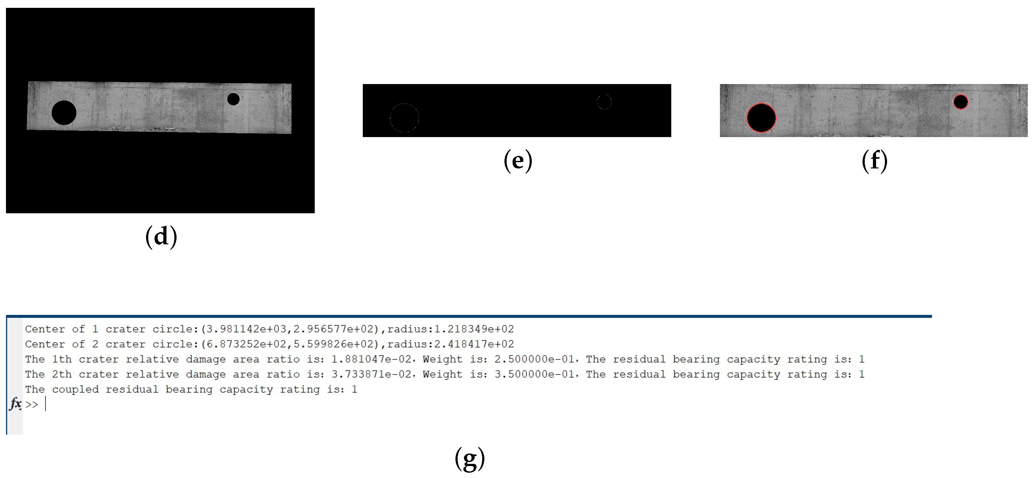
- For the screened damaged area, the relative damaged area ratio is calculated, which is defined as the ratio of the area of the damaged area (crater) to the area of the smallest bridge lateral area containing the damaged area, as shown in Figure 4. When the relative damage area ratio exceeds 50%, the crater area is too large, and the bridge may collapse directly, which divides the relative damage area ratio into 0–0.05, 0.05–0.1, 0.1–0.15, 0.15–0.2, 0.2–0.25, 0.25–0.3, 0.3–0.35, 0.35–0.4, 0.4–0.45, and 0.45–0.5. The ten intervals correspond to residual bearing capacity classes 1–10, respectively.
- According to the matching rule, the higher bearing capacity grade of the bridge abutment indicates that its residual bearing capacity is smaller and the degree of destruction is more serious according to the results of the third step of the calculation matching the residual bearing capacity grade of each strike position.
- Combined with the damage state of each damaged area and the location of the damage, the results of the residual bearing capacity level of each damaged area are a weighted coupling in order to ensure that the coupling is positively correlated and the range of values is unchanged; the calculation method is given in the following equation:where RBC denotes the final residual bearing capacity index value of the bridge abutment or bridge deck, T indicates the total number of damaged areas, indicates the residual bearing capacity index of the ith damaged area, and weight indicates the weight value of a certain type of damage.The functional destruction of the bridge abutment is equivalent to the structural destruction, and for the bridge abutment as a whole, its structural strength is consistent. According to the results of the static analysis, the size of the residual bearing capacity of the bridge abutment is negatively correlated with the strike height. Analyzed from the loading point of view, the stress underneath the bridge abutment is greater and the damage is more likely to cause collapse. It is assumed that the bridge deck and abutment cross-sectional area are of the same size. Considering only the case of self-weight, the stress magnitude at the height, h, of the abutment is:where denotes the density of reinforced concrete, g denotes the acceleration of gravity, H is the height of the bridge abutment, and L is the length of the bridge deck.For this experimental bridge, L = 30 m, H = 3 m. To simplify the calculation, the abutment is divided into upper and lower parts, and as the stress ratio of the upper and lower parts is about 1.1, the weight ratio is 1.1. The calculation can obtain that the upper half of the weight value is 0.48, and the lower half of the weight value is 0.52. The penetration damage and damage to the missing areas are regarded as a complete penetration with a penetration through half of the thickness, so its weight ratio is 2. Therefore, the weights of the damage types of the bridge piers are obtained as shown in Table 1.For bridge decks, more factors need to be considered in the calculation of residual capacity due to the presence of girders. T-girder bridges consist of flanges, webs, and wet joints. The wet joints occupy a small area and are equivalent in strength to the flanges, so the deck can be equated to the flanges and the web. For the general case of munitions strikes, the web will not be completely destroyed and may occur in the upper part of the missing area, which has a small impact on its mechanics, so the web destruction can be ignored. Therefore, for T-girder bridges without prestressing technology, the main damaged structure from a munitions strike is the T-girder flange, so when dealing with it, according to the most unfavorable conditions, the craters will all damage the girders.Analyzed from the loading point of view, the simplified bridge deck is subjected to an evenly distributed load, and the middle bending moment of the bridge deck is the largest and the damage is more likely to cause collapse. In order to simplify the calculation, the bridge deck is divided into four blocks, the two blocks near the center are one part, and the two ends are the other part, so its bending moment ratio is 2; i.e., the weight ratio is 2. Calculations can obtain that the weight value of the middle part of the bridge deck is 0.67, and the value for the two ends of the bridge deck is 0.33. For the penetrating and missing damage, it is considered to be a complete penetration with penetration through half of the thickness, so its weight ratio is 2. Therefore, the obtained weight values for the bridge deck damage types are shown in Table 1.
- Fusing the residual bearing capacity characteristics of the abutments and bridge decks, the method of taking the maximum value is used to ensure the accuracy and uniqueness of the final result, so it can be obtained that the residual bearing capacity characteristics of the bridge are calculated as follows:where RBC denotes the residual load rating after fusion, denotes the residual load rating of the abutment, and denotes the residual load rating of the deck.
3.2. Through-Lane Inspection
- Take one side corner of the bridge deck as the coordinate origin; the width of the bridge is W and the length is L. Set the width direction of the bridge as the x-axis, the length direction as the y-axis, and the width of the vehicle is set as W′, as shown in Figure 5.
- Combine the bridge deck change detection results to generate the crater location matrix and the diameter matrix of the crater, where the order in the sample crater location matrix is sorted from smallest to largest according to the size of the x-coordinate; is the x-coordinate, is the y-coordinate, M is the number of craters, and is the diameter of the ith crater. Calculate the distance between the centers of any two craters and form the distance square matrix D, where the elements of the square matrix can be calculated by the following equation:
- If square D does not exist, i.e., there is only one crater, skip to step 5.; if square D exists, compute the rows and columns of all elements in the lower triangular portion of square D (excluding the diagonal) that are smaller than , i.e., the numbering of the non-existing through-paths between the two craters, and form the matrix , in which each row contains the row numbering and the column numbering of the conforming elements, with the element on the left-hand side being the smaller numbered value, and the element on the right-hand side of the column being the numbering of the larger values; the different rows are sorted from smallest to largest according to the size of the elements on the left:where n is the number of elements less than in the lower triangular part of the D-square matrix;
- Combination of non-adjacent craters. Two craters with a distance between them of less than the width of the through-lane are referred to as immediate neighboring craters, and such craters are merged. Set a larger value of Lv, according to the read matrix of the consistency line of the left element , obtain the position matrix of the crater and the diameter matrix , calculate the smallest external rectangle that contains the crater, the formation of the rectangle index id, id value for the natural number from 1, the position matrix , and the length and width matrix of the rectangle . Then, calculate the minimum outer circle of the rectangle to obtain the location of the new “crater” and the “diameter” ; the “diameter” is calculated as follows:Combine all rectangular length–width matrices into a new matrix S in the order:Delete the read data from the original crater position and diameter matrix and add the new crater position and diameter data to form a new crater position matrix and diameter matrix .
- Render the bridge deck as a whole in white, and sequentially read the new crater position matrix and diameter matrix . If , it means that the crater is a rectangle; retrieve the length and width of the rectangle based on and render the rectangular region in black by combining positional information. If , it means that the crater is a circle; render the smallest outer rectangle of the circle in black based on positional and direct information.
- Read the new crater position matrix and the diameter matrix . If , set the width of the retrieval bar to be min and the length of the retrieval bar to be the width of the bridge deck and the retrieval bar to be rendered in white. Start from the bottom of the area, perform the “and” operation of the retrieval bar with the bridge deck, delete the white areas whose widths are smaller than the width of the retrieval bar, and calculate the sum of downward integer values of the length of the white areas divided by the width of the vehicle after the operation. Calculate the length of each white area after the operation divided by the width of the vehicle W’ and the downward integer value of OP. After retrieving this area, record the information of this crater and the minimum value of its OP; if , set the width of the retrieval bar to , and the rest of the operation is the same as above. Finally, compare the OP values and output the minimum value and its crater information.
- Based on the crater information and OP values from the previous step, calculate whether the crater has any craters in the range . If the crater exists, then ; if not, then . The final calculated OP value is the number of lanes.
3.3. Indicator Convergence
- Residual bearing capacity (RBC). According to the residual bearing capacity index extraction method proposed in Section 3.1, the residual bearing capacity grade of the girder bridge can be obtained, and the value range of the result is [0, 10], and the larger the value is, the lower the residual bearing capacity of the bridge is;
- Number of lanes (OP). According to the through-lane detection algorithm proposed in Section 3.2, the number of parallel lanes of the bridge can be obtained as OP. The value is an integer starting from 0, and the maximum value is the downward rounding value of the bridge width divided by the vehicle width result. For bridges of different widths, the OP value has a different value range, so in order to ensure the consistency of the damage indicators, the number of lanes, OP, is converted to a value in the range of 0–10, and the larger the value, the lower the number of through-lanes; the conversion is as follows:where W denotes the width of the bridge deck and W denotes the width of the vehicle;
4. Experimental Validation and Results
5. Conclusions
Author Contributions
Funding
Institutional Review Board Statement
Informed Consent Statement
Data Availability Statement
Conflicts of Interest
References
- Yan, Q.; Li, S.; Chen, Y.; Lv, C. Analysis and research on structural vulnerability of bridges under the effect of blast loads. Prot. Eng. 2022, 44, 71–78. [Google Scholar]
- Rauch, J.T., Jr. Assessing Airpower’s Effects: Capabilities and Limitations of Real-Time Battle Damage Assessment; Air Univ Maxwell Afb AI School of Advanced Airpower Studies: Montgomery, AL, USA, 2002; Available online: https://scholar.google.com/scholar_lookup?title=Assessing+Airpower%E2%80%99s+Effects:+Capabilities+and+Limitations+of+Real-Time+Battle+Damage+Assessment&author=Rauch,+J.T.,+Jr.&publication_year=2002 (accessed on 5 December 2024).
- Gou, T. Research on Key Technologies of Damage Assessment System Based on Image Analysis. Ph.D. Thesis, Jilin University, Changchun, China, 2019. Available online: https://scholar.google.com/scholar?hl=zh-CN&as_sdt=0%2C5&q=%E5%9F%BA%E4%BA%8E%E5%9B%BE%E5%83%8F%E5%88%86%E6%9E%90%E7%9A%84%E6%AF%81%E4%BC%A4%E8%AF%84%E4%BC%B0%E7%B3%BB%E7%BB%9F%E5%85%B3%E9%94%AE%E6%8A%80%E6%9C%AF%E7%A0%94%E7%A9%B6+%E5%8B%BE%E6%B6%9B&btnG= (accessed on 5 December 2024).
- DI-2820-4-03; Battle Damage Assessment (BDA) Quick Guide. Defense Intelligence Agency (DIA): Washington, DC, USA, 1996. Available online: https://media.defense.gov/2017/Dec/27/2001861489/-1/-1/0/T_0016_RAUCH_ASSESSING_AIRPOWERS_EFFECTS.PDF (accessed on 5 December 2024).
- Meade, T.E.; Hopkins, J.A.; Fujiwara, M.M. Battle damage assessment: The road to victory. Mil. Intell. Prof. Bull. 1998, 24, 38–41. Available online: https://search.ebscohost.com/login.aspx?direct=true&db=mth&AN=869277&lang=zh-cn&site=ehost-live (accessed on 5 December 2024).
- Zhang, C.; Shu, J.; Wu, J.; Su, G. Current status and development of target damage effect evaluation technology. Aerodyn. Missile J. 2017, 6, 68–72. [Google Scholar] [CrossRef]
- Tu, Z.; Lin, T. Research on Battle Damage Assessment System Based on Downward-looking Scene Image. Tactical Missile Technol. 2012, 5, 6–9. Available online: https://scholar.google.com/scholar_lookup?title=Research+on+Battle+Damage+Assessment+System+Based+on+Downward-looking+Scene+Image&author=Tu,+Z.&author=Lin,+T.&publication_year=2012&journal=Tactical+Missile+Technol.&volume=5&pages=6%E2%80%939 (accessed on 5 December 2024).
- Chen, P.; Ji, Z.; Yang, S.; Li, T. Analysis of Evaluation Method for Joint Operations of US Army. Ordnance Ind. Autom. 2023, 42, 71–75. [Google Scholar] [CrossRef]
- Zhang, J. Processing Method of Multi-Temporal Remote Sensing Images and the Use in Damage Assessment. Ph.D. Thesis, Shanghai Jiao Tong University, Shanghai, China, 2018. Available online: https://scholar.google.com/scholar?hl=zh-CN&as_sdt=0%2C5&q=%E5%A4%9A%E6%97%B6%E7%9B%B8%E5%9B%BE%E5%83%8F%E6%A3%80%E6%B5%8B%E6%96%B9%E6%B3%95%E5%8F%8A%E5%85%B6%E5%9C%A8%E6%AF%81%E4%BC%A4%E8%AF%84%E4%BC%B0%E7%B3%BB%E7%BB%9F%E4%B8%AD%E7%9A%84%E5%BA%94%E7%94%A8&btnG= (accessed on 5 December 2024). (In Chinese).
- Niu, P.; Li, W.; Li, X. An Airport Damage Assessment Algorithm Based on Change Detection. Electron. Opt. Control 2012, 19, 89–93. Available online: https://scholar.google.com/scholar?cluster=17850735731735192316&hl=zh-CN&as_sdt=0,5 (accessed on 5 December 2024). (In Chinese).
- Yu, T. Remote Sensing Image Change Detection and Damage Assessment Application Based on Multi-Scale Fusion. Ph.D. Thesis, University of Electronic Science and Technology of China, Chengdu, China, 2010. Available online: https://scholar.google.com/scholar?hl=zh-CN&as_sdt=0%2C5&q=%E5%9F%BA%E4%BA%8E%E5%A4%9A%E5%B0%BA%E5%BA%A6%E8%9E%8D%E5%90%88%E7%9A%84%E9%81%A5%E6%84%9F%E5%9B%BE%E5%83%8F%E5%8F%98%E5%8C%96%E6%A3%80%E6%B5%8B%E5%8F%8A%E5%85%B6%E6%AF%81%E4%BC%A4%E8%AF%84%E4%BC%B0%E5%BA%94%E7%94%A8&btnG= (accessed on 5 December 2024). (In Chinese).
- Li, W.; Chen, Q. Ship battle damage assessment based on remote sensing images. Ship Electron. Eng. 2014, 34, 50–52. [Google Scholar]
- Ji, H.; Yang, Q. Airport runway functional damage assessment based on image analysis. J. Comput. Appl. 2016, 36, 165–168. Available online: https://scholar.google.com/scholar?hl=zh-CN&as_sdt=0%2C5&q=Airport+runway+functional+damage+assessment+based+on+image+analysis&btnG= (accessed on 5 December 2024).
- Pu, G.; Xu, P.; Ren, P.; Xue, Z. Research on damage effect assessment of airport runways based on image analysis. Ship Electron. Eng. 2012, 32, 31–32. Available online: https://scholar.google.com/scholar?hl=zh-CN&as_sdt=0%2C5&q=%E5%9F%BA%E4%BA%8E%E5%9B%BE%E5%83%8F%E5%88%86%E6%9E%90%E7%9A%84%E6%9C%BA%E5%9C%BA%E8%B7%91%E9%81%93%E6%AF%81%E4%BC%A4%E6%95%88%E6%9E%9C%E8%AF%84%E4%BC%B0%E7%A0%94%E7%A9%B6&btnG= (accessed on 5 December 2024).
- Liu, J. Research and Implementation of Target Damage Assessment Based on Functional Characteristics Analysis. Ph.D. Thsis, Beijing University of Technology, Beijing, China, 2013. Available online: https://scholar.google.com/scholar?hl=zh-CN&as_sdt=0%2C5&q=%E5%9F%BA%E4%BA%8E%E5%8A%9F%E8%83%BD%E7%89%B9%E6%80%A7%E5%88%86%E6%9E%90%E7%9A%84%E7%9B%AE%E6%A0%87%E6%AF%81%E4%BC%A4%E8%AF%84%E4%BC%B0%E7%AE%97%E6%B3%95%E7%A0%94%E7%A9%B6%E4%B8%8E%E5%AE%9E%E7%8E%B0&btnG= (accessed on 5 December 2024). (In Chinese).
- Gu, D.; Zeng, L.; Yang, X. Study of target damage evaluation methods based on image. Comput. Eng. Appl. 2012, 48 (Suppl. 2), 417–421. Available online: https://scholar.google.com/scholar?hl=zh-CN&as_sdt=0%2C5&q=%E5%9F%BA%E4%BA%8E%E5%9B%BE%E5%83%8F%E7%9A%84%E7%9B%AE%E6%A0%87%E6%AF%81%E4%BC%A4%E8%AF%84%E4%BC%B0%E6%96%B9%E6%B3%95%E7%A0%94%E7%A9%B6&btnG= (accessed on 5 December 2024). (In Chinese).
- Liu, W.; Li, S.; Chi, D.; Li, M. Method and model of the airports battle damage assessment. J. Geomat. Sci. Technol. 2015, 32, 36–41. [Google Scholar] [CrossRef]
- Wang, Y.; Zhang, C.; Song, Y. Research on joint fire-strike battle damage assessment based on optical remote sensing image. In Proceedings of the 2014 China Conference on Command and Control, Nanjing, China, 4–5 August 2014; Volume 1, pp. 333–336. Available online: https://scholar.google.com/scholar?hl=zh-CN&as_sdt=0%2C5&q=%E5%9F%BA%E4%BA%8E%E5%85%89%E5%AD%A6%E5%9B%BE%E5%83%8F%E7%9A%84%E8%81%94%E5%90%88%E7%81%AB%E5%8A%9B%E6%89%93%E5%87%BB%E6%95%88%E6%9E%9C%E8%AF%84%E4%BC%B0%E7%A0%94%E7%A9%B6&btnG= (accessed on 5 December 2024). (In Chinese).
- Xu, Y.; Yu, Q.; Wang, Y.; Xiao, J.; Zhou, Z.; Lu, H. Ground target detection and damage assessment by patrol missiles based on YOLO-VGGNet. Appl. Sci. 2022, 12, 9484. [Google Scholar] [CrossRef]
- Berezina, P.; Liu, D. Hurricane damage assessment using coupled convolutional neural networks: A case study of hurricane Michael. Geomat. Nat. Hazards Risk 2022, 13, 414–431. [Google Scholar] [CrossRef]
- Zhang, Z.; Zhang, L.; Xie, C.; Zhang, B.; Yang, B. Battle damage effect assessment based on improved ga-bp neural network. Fire Control Command Control 2021, 46, 43–48. [Google Scholar] [CrossRef]
- Qu, W.; Xu, Z.; Liu, Y. Damage assessment of radar position based on ga-dynamic bp neural network. Tactical Missile Technol. 2016, 6, 51–57. [Google Scholar] [CrossRef]
- Jiang, H.; Wang, S.; Li, Z.; Zhang, Y.; Zhai, H. Effectiveness evaluation of blockade cluster warhead against bridge target. Acta Armamentarii 2016, 37 (Suppl. 1), 1–6. Available online: https://scholar.google.com/scholar?cluster=15179536351683300620&hl=zh-CN&as_sdt=0,5 (accessed on 5 December 2024). (In Chinese).
- Wu, Z.; Zhao, Z. Research on damage of common shell group to area target based on fuzzy system. J. Syst. Simul. 2013, 25, 1166–1169. Available online: https://scholar.google.com/scholar?cluster=5560032915788454815&hl=zh-CN&as_sdt=0,5 (accessed on 5 December 2024). (In Chinese).
- Gao, W.; Sun, G.; Chen, L.; Zhou, C.; Liu, R. Research on damage assessment technology of ground building. Prot. Eng. 2019, 41, 48–53. Available online: https://scholar.google.com/scholar?hl=zh-CN&as_sdt=0%2C5&q=%E5%9C%B0%E9%9D%A2%E5%BB%BA%E7%AD%91%E6%AF%81%E4%BC%A4%E8%AF%84%E4%BC%B0%E6%8A%80%E6%9C%AF%E7%A0%94%E7%A9%B6&btnG= (accessed on 5 December 2024). (In Chinese).
- Yuan, S.; Yang, K.; Liu, Z.; Zong, Z. Numerical simulation of damage mode and axial load effect of RC bridge columns under close-in explosion. J. Southeast Univ. (Nat. Sci. Ed.) 2023, 53, 76–85. [Google Scholar] [CrossRef]
- Li, H.; Mei, D.; Zhang, Y.; Chang, J. An analysis of the effect of the missile stricken position on the damage of a box girder. Traffic Eng. Technol. Natl. Def. 2019, 17, 20–23. [Google Scholar] [CrossRef]
- Yang, S.; Zhong, W.; Wang, S.; Kong, W.; Tang, Z.; Tian, Z.; Zhang, R.; Yao, X. On dynamic analysis and damage evaluation for bridge girders under high-energy air burst. Structures 2022, 41, 1488–1500. [Google Scholar] [CrossRef]
- Tong, C.; Zhang, J.; Ji, H. Residual resistance and bearing mechanism of RC beam after impact. J. Vib. Shock. 2023, 42, 122–130. (In Chinese) [Google Scholar] [CrossRef]
- Chen, S.; Zhao, H.; Li, J.; Zhu, C. Reliability assessment of a concrete beam bridge under actual traffic load. J. Vib. Shock. 2022, 41, 158–167. (In Chinese) [Google Scholar] [CrossRef]
- Duque, L.; Seo, J.; Wacker, J. Bridge deterioration quantification protocol using UAV. J. Bridge Eng. 2018, 23, 04018080. [Google Scholar] [CrossRef]
- Perry, B.J.; Guo, Y.; Atadero, R.; van de Lindt, J.W. Streamlined bridge inspection system utilizing unmanned aerial vehicles (UAVs) and machine learning. Measurement 2020, 164, 108048. [Google Scholar] [CrossRef]
- Yamaguchi, T.; Hashimoto, S. Fast crack detection method for large-size concretesurface images using percolation-based image processing. Mach 2010, 21, 797–809. [Google Scholar] [CrossRef]
- Yamaguchi, T.; Nakamura, S.; Hashimoto, S. An efficient crack detection method using percolation-based image processing. In Proceedings of the 2008 3rd IEEE Conference on Industrial Electronics and Applications, Singapore, 3–5 June 2008; pp. 1875–1880. [Google Scholar] [CrossRef]
- Nguyen, H.N.; Kam, T.Y.; Cheng, P.Y. A novel automatic concrete surface crack identification using isotropic undecimated wavelet transform. In Proceedings of the 2012 International Symposium on Intelligent Signal Processing and Communications Systems, Chiang Mai, Thailand, 2–4 December 2012; pp. 766–771. [Google Scholar] [CrossRef]
- Lee, B.Y.; Kim, Y.Y.; Yi, S.T.; Kim, J.K. Automated image processing technique for detecting and analysing concrete surface cracks. Struct. Infrastruct. Eng. 2013, 9, 567–577. [Google Scholar] [CrossRef]
- Prasanna, P.; Dana, K.J.; Gucunski, N.; Basily, B.B.; La, H.M.; Lim, R.S.; Parvardeh, H. Automated crack detection on concrete bridges. IEEE Trans. Autom. Sci. Eng. 2014, 13, 591–599. [Google Scholar] [CrossRef]
- Kang, Z.; Wang, M.; Jia, K.; Liu, S. Study on damage assessment for bridge based on template matching. J. Syst. Simul. 2008, 5, 1114–1117. Available online: https://scholar.google.com/scholar?cluster=3548604510601718793&hl=zh-CN&as_sdt=0,5 (accessed on 5 December 2024). (In Chinese).
- Siavash, K.; Mohsen, E.M. An impulse noise fading technique based on local histogram processing. In Proceedings of the IEEE International Symposium on Signal Processing and Information Technology (ISSPIT), Ajman, United Arab Emirates, 4–17 December 2009; Volume 24, pp. 190–195. [Google Scholar] [CrossRef]
- American Association of State Highway and Transportation Officials (AASHTO). Policy on Geometric Design of Highways and Streets, 7th ed.; American Association of State Highway and Transportation Officials: Washington, DC, USA, 2018; ISBN 978-1-56051-623-1. [Google Scholar]


| Types of Bridge Pier Damage | Weights | Types of Bridge Deck Damage | Weights |
|---|---|---|---|
| Upper part of the body is penetrated and destroyed | 0.32 | Penetrating damage to the center section of the bridge deck | 0.45 |
| Upper part of the body is missing and destroyed | 0.16 | Missing and damaged center section of bridge deck | 0.22 |
| Lower part of the body is penetrated and destroyed | 0.347 | Partial penetrating damage to both ends of the bridge deck | 0.22 |
| Lower part of the body is missing and destroyed | 0.173 | Partial loss of damage to both ends of the bridge deck | 0.11 |
| Girder Bridge Damage Grade | Composite Damage Indicator Value |
|---|---|
| Slight damage | |
| Moderate damage | |
| Severe damage | AG > 5 |
Disclaimer/Publisher’s Note: The statements, opinions and data contained in all publications are solely those of the individual author(s) and contributor(s) and not of MDPI and/or the editor(s). MDPI and/or the editor(s) disclaim responsibility for any injury to people or property resulting from any ideas, methods, instructions or products referred to in the content. |
© 2024 by the authors. Licensee MDPI, Basel, Switzerland. This article is an open access article distributed under the terms and conditions of the Creative Commons Attribution (CC BY) license (https://creativecommons.org/licenses/by/4.0/).
Share and Cite
Chen, X.; Zhai, H.; Xu, Q.; Wei, W. Research on Damage Assessment Method for Reinforced Concrete T-Girder Bridges Under Munitions Strikes. Appl. Sci. 2024, 14, 11422. https://doi.org/10.3390/app142311422
Chen X, Zhai H, Xu Q, Wei W. Research on Damage Assessment Method for Reinforced Concrete T-Girder Bridges Under Munitions Strikes. Applied Sciences. 2024; 14(23):11422. https://doi.org/10.3390/app142311422
Chicago/Turabian StyleChen, Xi, Hongbo Zhai, Qipeng Xu, and Wei Wei. 2024. "Research on Damage Assessment Method for Reinforced Concrete T-Girder Bridges Under Munitions Strikes" Applied Sciences 14, no. 23: 11422. https://doi.org/10.3390/app142311422
APA StyleChen, X., Zhai, H., Xu, Q., & Wei, W. (2024). Research on Damage Assessment Method for Reinforced Concrete T-Girder Bridges Under Munitions Strikes. Applied Sciences, 14(23), 11422. https://doi.org/10.3390/app142311422