Article

Numerical Simulation and Engineering Application of Temporary Stress Field in Coal Mine Roadway

1
School of Mechanical Engineering, Xi’an University of Science and Technology, Xi’an 710054, China
2
Shaanxi Key Laboratory of Mine Electromechanical Equipment Intelligent Detection and Control, Xi’an 710054, China
*
Authors to whom correspondence should be addressed.
Appl. Sci. 2024, 14(23), 11420; https://doi.org/10.3390/app142311420
Submission received: 5 October 2024 / Revised: 23 November 2024 / Accepted: 6 December 2024 / Published: 8 December 2024

Abstract

:
The imbalance between excavation and mining is significant as it restricts the efficient development of coal resources. Slow tunneling speed is primarily due to the inability to concurrently conduct excavation and permanent support operations, and temporary support is considered a key solution to this problem. However, the mechanism by which temporary support affects the surrounding rock in unsupported are as remains unclear, hindering the assurance of stability in these areas and the determination of a reasonable unsupported span. To address this issue, this work proposed a stress distribution model as temporary support, elucidating the distribution law of support forces within the surrounding rock. By analyzing the stress differences between areas with and without temporary support, the stress field distribution characteristics of temporary support were determined. Subsequently, the evolution of stress and strain in the surrounding rock within unsupported areas was analyzed concerning changes in temporary support length, support force, and unsupported distance. The results indicated that, although temporary support does not directly act on unsupported areas, it still generates a supportive stress field within them. The maximum unsupported distance should not exceed 3 m, and there is a strong linear relationship between the optimal temporary support force and the unsupported span. Furthermore, the length of temporary support should not exceed 17 m from the tunnel face. The successful application of the shield tunneling robot system verifies that temporary support can ensure the stability of the surrounding rock in unsupported areas, confirming the validity of the temporary support stress distribution model. This research can be used to design and optimize cutting parameters and temporary support parameters, arrange equipment, and design and optimize tunnel excavation processes to achieve safe and efficient tunneling.

1. Introduction

The driving face encounters challenges such as complex working conditions, numerous processes, and low equipment intelligence, all of which prevent significant improvements in driving speed [1,2,3]. Due to the narrow space near the tunnel face, the excavating machine must retreat after excavation to provide permanent support [4,5]. Consequently, each excavation cycle involves multiple steps, resulting in a daily excavation progress of only about 10 m in some tunnels [6,7,8,9,10]. The application of temporary support allows for permanent support operations to lag behind in a broader space, enabling parallel operations of excavation and permanent support [11,12,13]. Therefore, the adoption of safe and reliable temporary support is a critical means to improve excavation efficiency and address the imbalance between excavation and mining. Current temporary support technologies and equipment facilitate parallel operations of excavation and permanent support to some extent, but the enhancement in excavation efficiency remains limited [14,15,16,17,18,19,20,21]. In the absence of a clear maximum unsupported distance, the maximum excavation distance is typically conservatively set to 0.8 m or 1 m. This conservative approach does not genuinely achieve independent operations of excavation and permanent support, thereby significantly restricting the potential increase in excavation speed [22,23,24,25]. Thus, it is crucial to investigate the mechanism of temporary support on the surrounding rock in unsupported areas and to analyze the influence of temporary support parameters on the stress and strain behavior of the surrounding rock in these areas. Understanding these factors is essential for ensuring the stability of the surrounding rock and for achieving truly parallel operations of excavation and permanent support.
Ensuring the stability of the surrounding rock under temporary support is a prerequisite for rapid tunneling. Scholars have analyzed the effects of stress variations [26], support schemes [27], construction conditions [28], and other factors on rock stability. Temporary support and the surrounding rock work in synergy, forming an interdependent and tightly integrated system that effectively coordinates deformation [29,30,31,32]. Without altering the characteristics of the surrounding rock, the support structure is crucial in maintaining rock stability under various conditions. Scholars have studied the stress–strain behavior of temporary support during excavation [33,34,35], as well as the response characteristics of temporary support to static loads [36,37,38] and dynamic loads [39,40,41] on the surrounding rock. The support structure actively alters the stress state of the surrounding rock to maintain stability, with the stress field being a core issue reflecting the stability and failure of the rock and the interaction between the rock and the support [42,43]. Using simulation software, scholars have analyzed the stress fields of rock bolts under different geological conditions based on coal mine geology [44,45,46,47,48]. As an elongated rod, the support stress field generated by a rock bolt within the surrounding rock far exceeds its own dimensions, and the related parameters of the rock bolt affect the distribution characteristics of the stress field [49,50,51,52,53,54]. Therefore, the stress field of temporary support will not be confined to the supported location alone. The related parameters of support are crucial in determining equipment selection, cutting parameters, and control parameters. Scholars have analyzed the relationships between tunnel parameters, rock characteristics, unsupported span, support force, support location, and the stress–strain behavior of the surrounding rock [55,56,57,58,59,60]. Among these factors, temporary support force and maximum unsupported span are the most critical factors in ensuring rock stability and improving tunneling efficiency. However, there has been limited research on the effects of temporary support on the surrounding rock in unsupported areas, particularly regarding the main parameters of temporary support, including temporary support length, temporary support force, and maximum unsupported distance, and their impacts on the stress–strain behavior of the surrounding rock in unsupported areas. This lack of clarity hinders the ability to ensure the stability of the surrounding rock in unsupported areas and to determine a reasonable unsupported span, which is a key limitation in enhancing tunneling efficiency.
In this work, a stress distribution model for temporary support was developed to clarify the distribution characteristics of support forces within the surrounding rock. The impact of temporary support force, support length, and unsupported distance on the stress–strain behavior of the tunnel roof was further investigated through simulated tunnel excavation and support experiments. The model assumes that the temporary support applies a normal, uniform force on a semi-infinite plane. By performing two integrations, the distribution law of the temporary support force within the tunnel was derived. The difference in stress between unsupported areas with and without temporary support reveals that temporary support creates a stress field in the unsupported area. Analysis of this stress differential demonstrates that temporary support induces a beneficial stress field in these areas. Based on the linear relationship between the optimal support force and unsupported distance, the necessary optimal temporary support force for the unsupported area was calculated from this distance. The evolution of roof stress–strain with varying unsupported distances indicates that roof strain increases minimally when the unsupported distance is less than 3 m, as the attenuation of temporary support stress is minimal in this range. Finally, the correlation between unsupported distance, temporary support length, and roof stress–strain behavior was explored, identifying a distinct inflection point 18 m from the tunnel face. Beyond this distance, roof stress increased significantly, while it remained relatively stable up to this point.

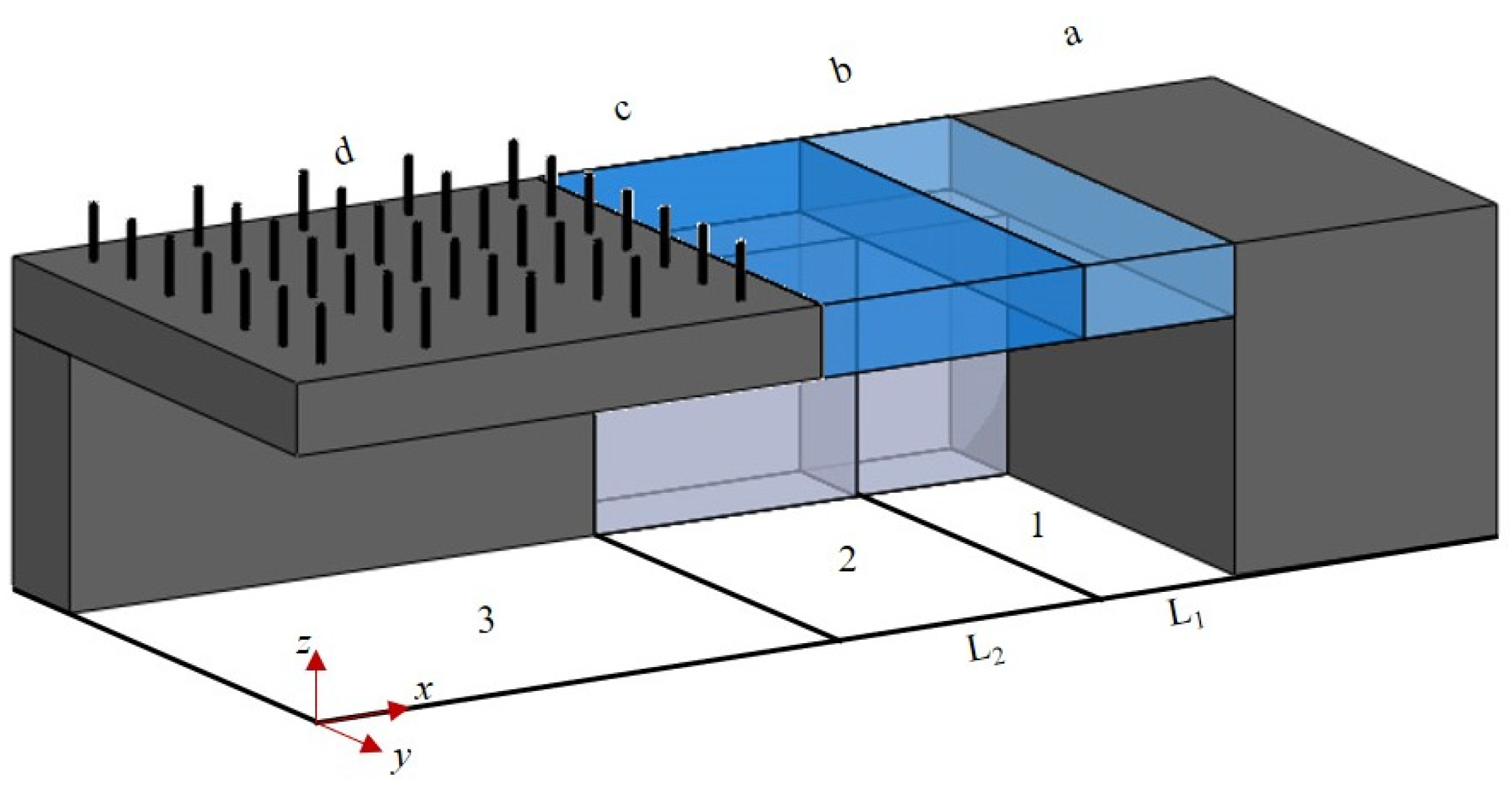
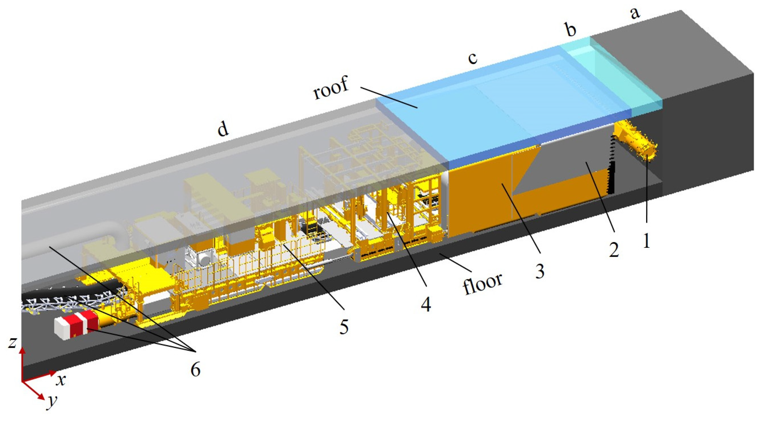
2. Rapid Tunneling System Area Division

Based on the spatial relationship between the equipment and the surrounding rock, the tunnel is divided into four areas: the unexcavated area, the unsupported area, the temporary support area, and the permanent support area, as shown in Figure 1. Among these, the unexcavated area refers to the area that has not yet been excavated. The unsupported area is where the excavation has been completed but the temporary support is missing. The temporary support area is the section where the support equipment has a direct effect. The permanent support area refers to the location where bolting and other works have been completed, resulting in a stable surrounding rock formation [61,62,63,64,65].
Due to the presence of temporary support, excavation and permanent support can be carried out in parallel, significantly improving tunneling efficiency [66,67,68,69,70,71]. A reasonable unsupported roof distance can effectively reduce the frequency of equipment relocation, further enhancing efficiency. When the stability of the surrounding rock is ensured, a larger unsupported roof distance allows for longer excavation sections, reducing the frequency of equipment movement. In addition, the unsupported roof distance also affects the temporary support force and the length of the temporary support area.

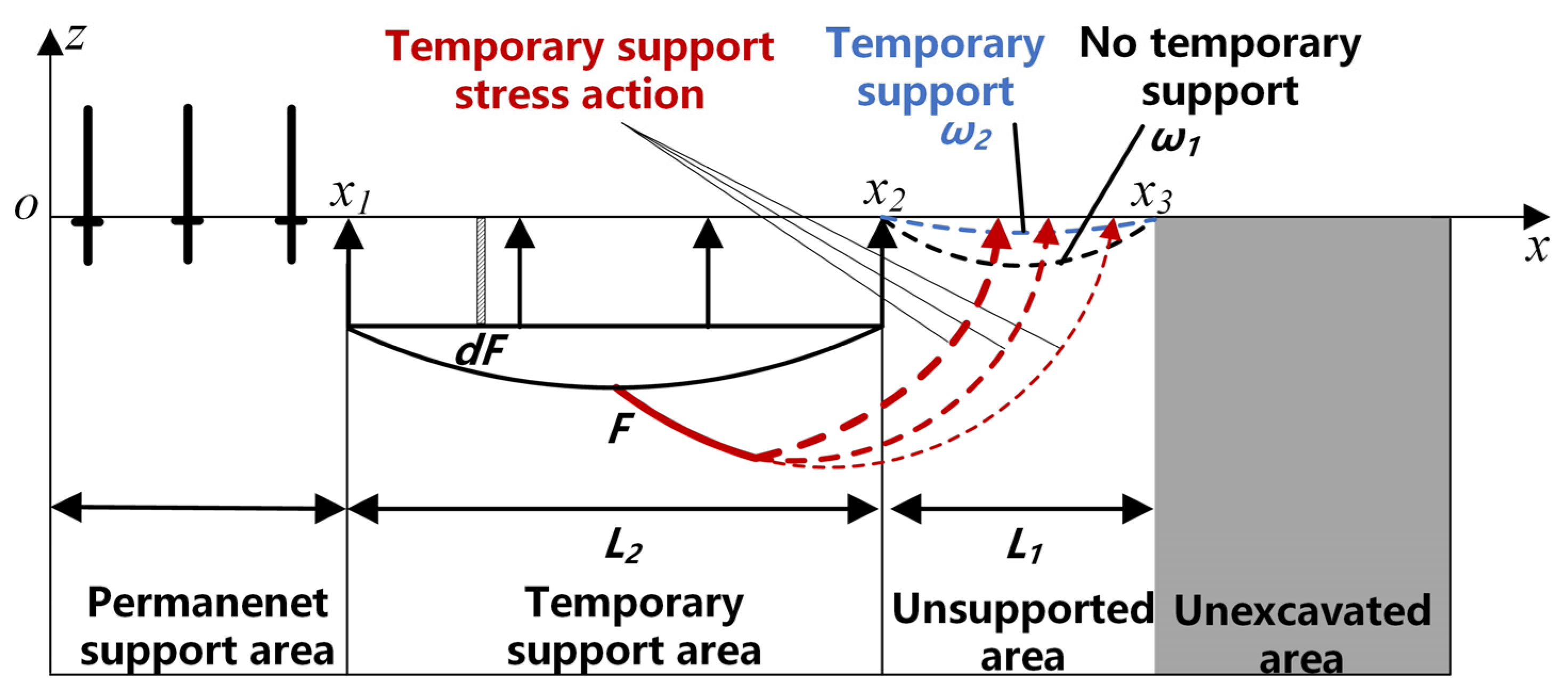
3. Construction of Stress Distribution Model for Temporary Support

As shown in Figure 2, the surrounding rock in the roadway is considered to be an infinite beam, which conforms to the assumption of stress distribution.
Therefore, the effect of the temporary supporting force on the surrounding rock can be considered as a normal uniform force acting on a semi-infinite plane. It is evident that exists a radial stress caused by force σ1 at any given point.
σ 1 = F z 3 ( z 2 + ( x ξ ) 2 ) 2 d ξ = 0.5 F a r c t a n ( ξ z 1 x z 1 ) + 0.5 F z ( ξ x ) ( z 2 + ( ξ x ) 2 ) 1
The radial stress σ2 induced by the temporary support force F at any given point can be determined by integrating σ1 over the interval x1-x2:
σ 2 = 2 π 1 x 1 x 2 F z 3 ( z 2 + ( x ξ ) 2 ) 2 d ξ = F π 1 [ a r c t a n ( x z 1 x 1 z 1 ) a r c t a n ( x z 1 x 2 z 1 ) + z ( x x 1 ) ( z 2 + ( x x 1 ) 2 ) 1 z ( x x 2 ) ( z 2 + ( x x 2 ) 2 ) 1 ]
The temporary support force F in the headspace can be determined by integrating σ2 over the interval x2-x3:
σ = F π 1 [ ( x 1 x 3 ) a r c t a n ( x 1 z 1 x 3 z 1 ) ( x 2 x 3 ) a r c t a n ( x 2 z 1 x 3 z 1 ) ( x 1 x 2 ) a r c t a n ( x 1 z 1 x 2 z 1 ) ]
The distribution characteristics of the temporary support force can be derived from mathematical model of Equation (3). The distribution of the temporary support force F in the unsupported area can be classified into three distinct stages, as shown in Figure 3a. The temporary support force hardly attenuates in area I. The temporary support force decays more rapidly in area II. The temporary support force attenuates to a very small value in area III and remains nearly constant thereafter. As observed from Figure 3b, the temporary support force initially increases and then decreases as the distance from the roof increases along the z-axis, peaking at a distance of 3 m. It is crucial to ensure that the unsupported area remains within the area I at all times, aligning with the actual working conditions on-site.

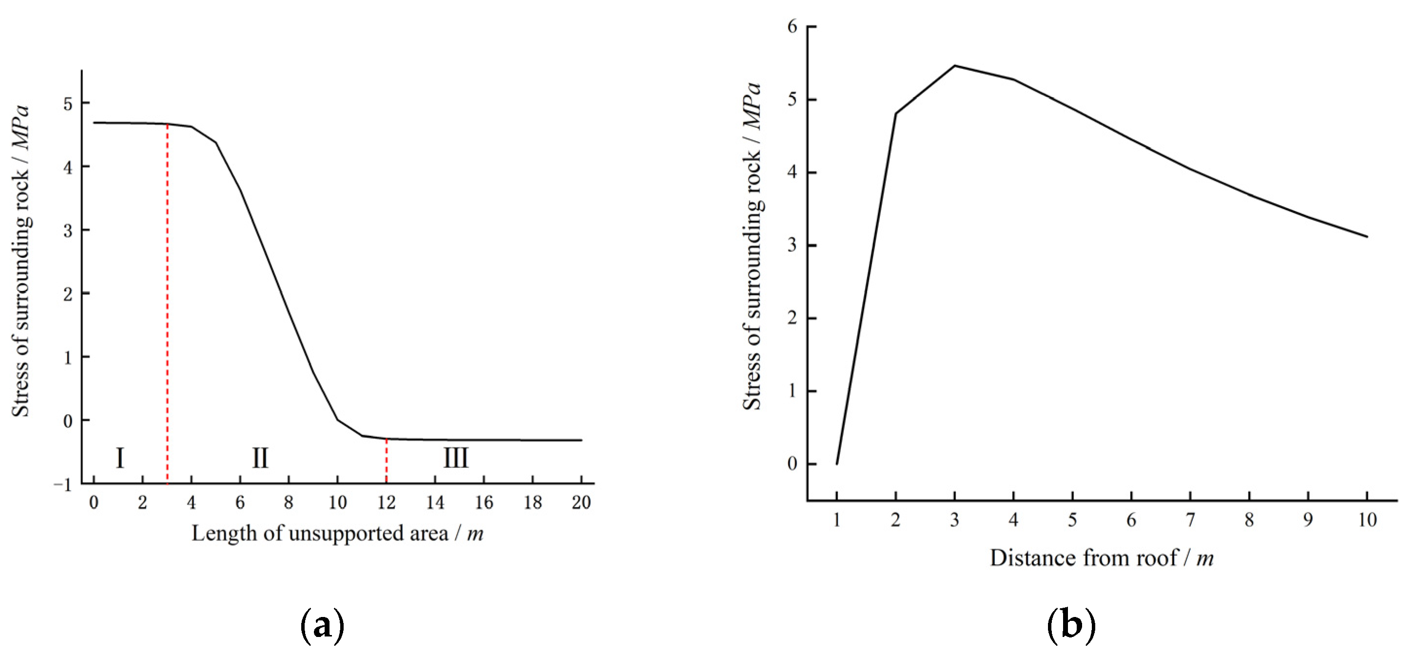
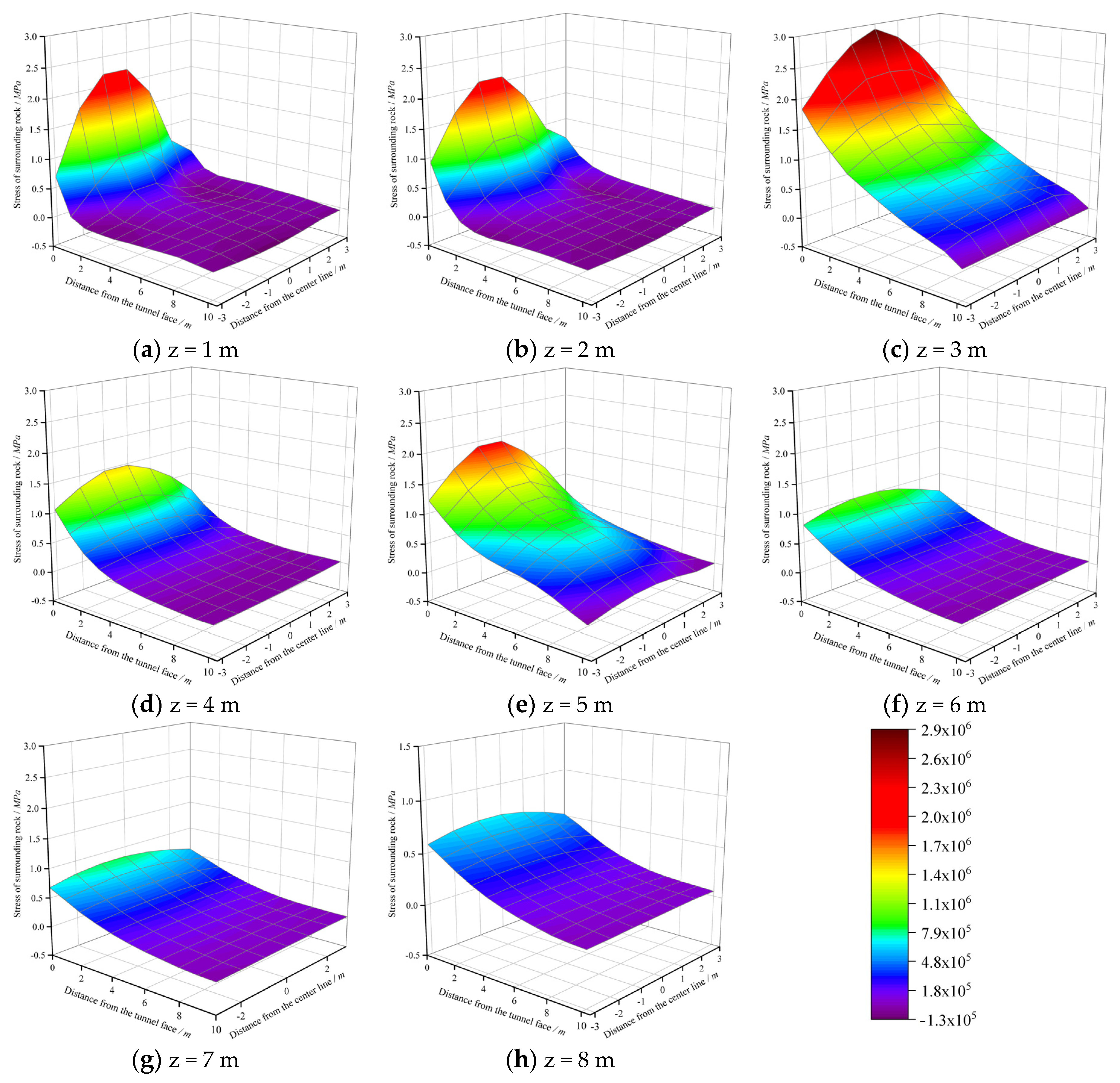
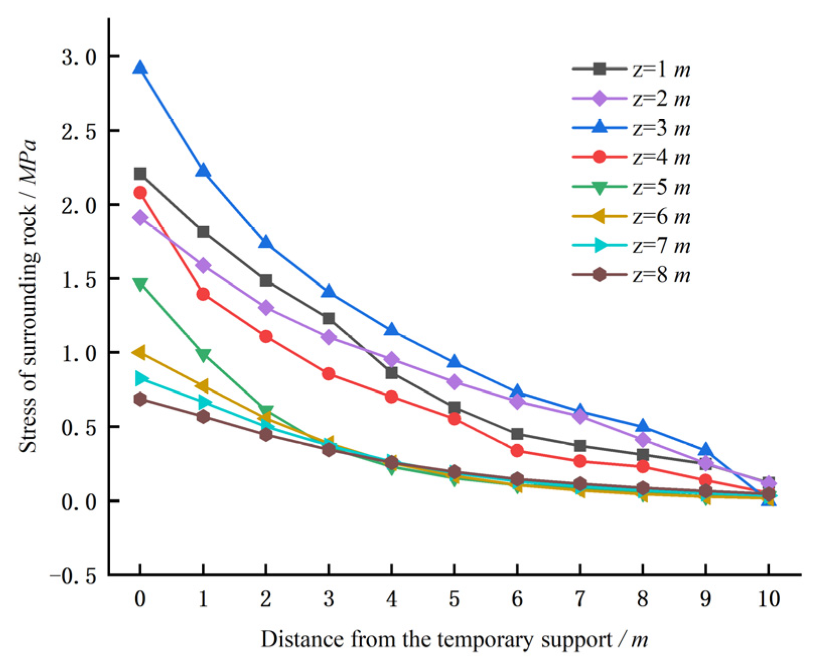
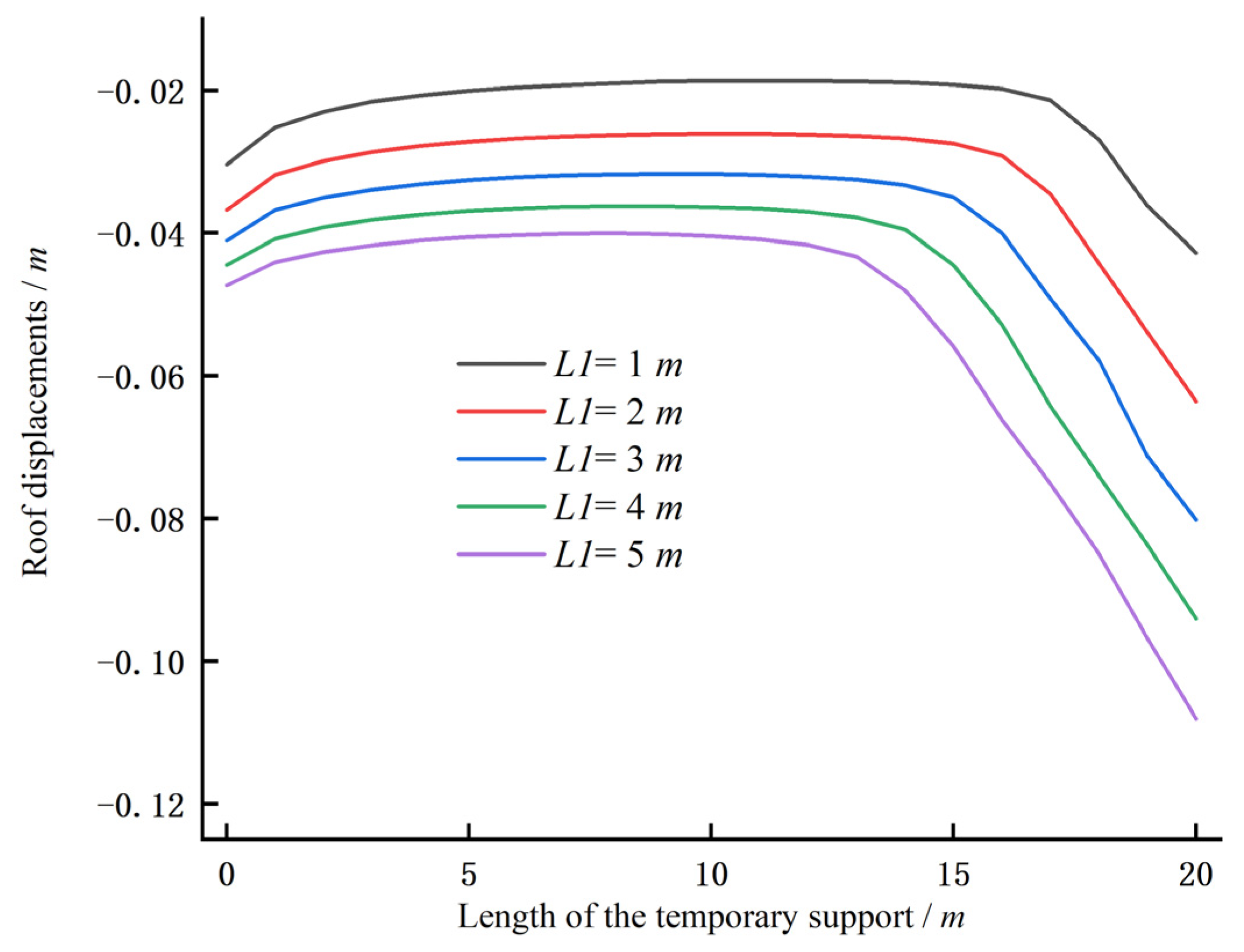
4. Distribution Characteristics of Temporary Support Stress Field in Unsupported Area

Different forms of support induce distinct stress fields in the surrounding rock, as a slender rod-like element, the rock bolt induces a stress field in the surrounding rock that far exceeds its own dimensions [72,73,74,75]. To study the effect of temporary support on the unsupported area, it is essential to initially analyze the stress field generated by the temporary support in that area. However, the FLAC3D5.0 software cannot directly compute the temporary support stress field diffusing into the unsupported area [76,77,78,79]. Therefore, two sets of simulation experiments, A and B, were conducted to simulate the excavation and support of the same roadway. Experiment A represents the case without temporary support after excavation, and Experiment B represents the case with temporary support after excavation. By analyzing the stress differences between these two sets of experiments, the distribution characteristics of the temporary support stress in the unsupported area can be determined. The relevant surrounding rock parameters of Xiao baodang Mining Company are detailed in Table 1.
As shown in Figure 4 and Figure 5, the investigation of the stress field distribution characteristics in the surrounding rock of the unsupported area indicated that although the temporary support did not directly support the unsupported area, significant stress fields would still be generated there. The occurrence of these stress fields in the unsupported area can be attributed to the distribution of the temporary support force [80,81,82,83].
The variation law of the stress field of the temporary support in different height planes was investigated, and it was observed that the stress initially increased and subsequently decreased with increasing height. This difference may result from variations in the distribution of the temporary support force at different heights. This variation law is consistent with the rule obtained from the mathematical model (Figure 3b), which also verifies the model’s accuracy. In addition, there is a significant stress difference between the maximum stress at 3 m and the stress at other heights, which will result in a greater risk of roof separation at 3 m. Therefore, caution should be exercised when utilizing temporary support at the layered roof position. Furthermore, the stress field of the bolt support first decreases and then increases with an increase in height. Therefore, temporary support can complement bolt support effectively and improve the stability of the surrounding rock before permanent support [84,85].

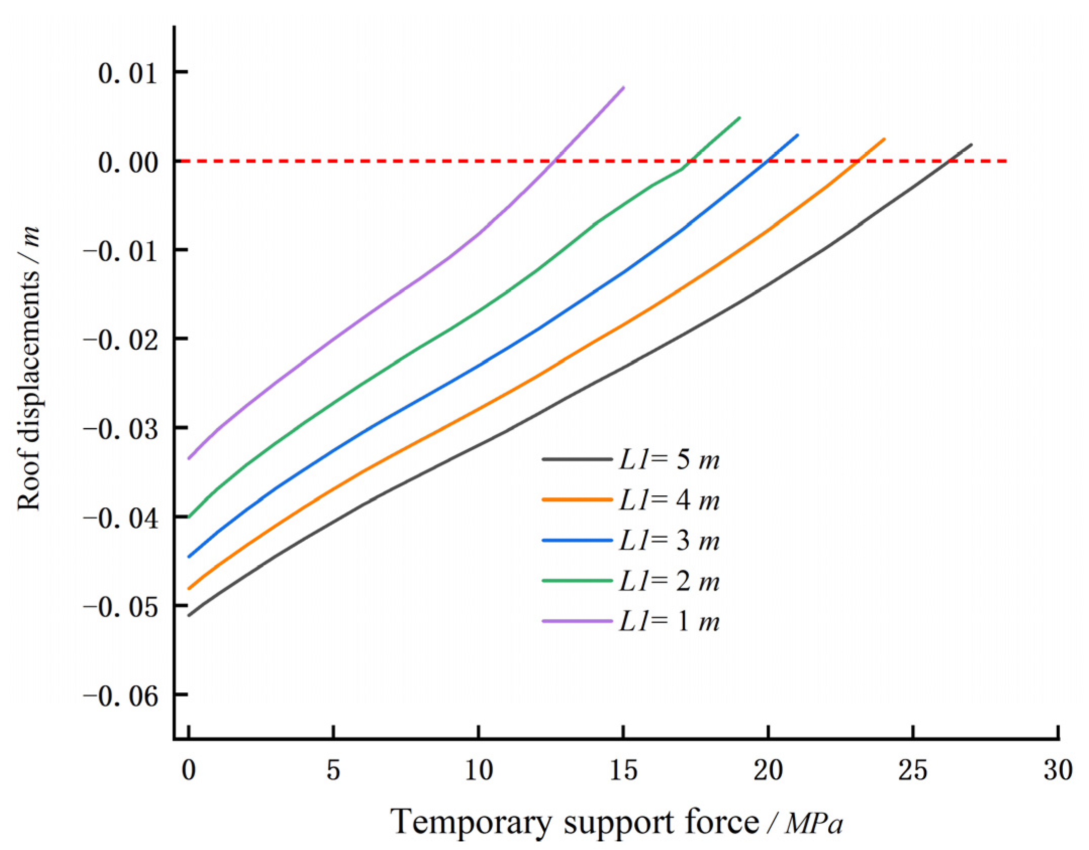
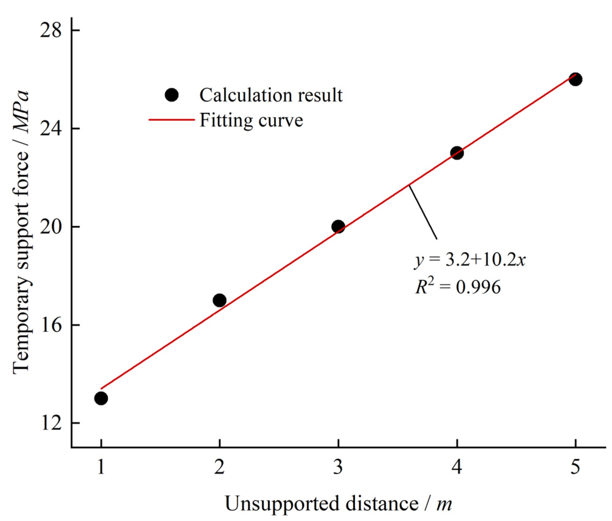
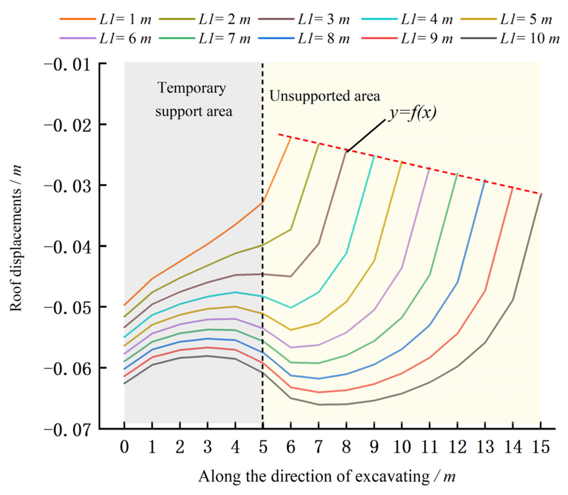
5. Analysis of Factors Influencing Stability of Surrounding Rock in Unsupported Areas

The key to safe and efficient excavation lies in ensuring the stability of the surrounding rock in the unsupported area. Changes in the parameters of temporary support lead to variations in the stress–strain characteristics of the surrounding rock within the unsupported area. The primary parameters of temporary support include the length of the supported area, the length of the unsupported area, and the magnitude of the temporary support force. The length of the supported area determines equipment requirements, the temporary support force plays a pivotal role in controlling the surrounding rock, and the unsupported distance dictates the maximum spacing between excavation rows [86,87,88,89,90].
Initially, the relationship between the temporary support force and roof strain in the unsupported area was investigated. It was observed that roof strain decreased with increasing temporary support force, indicating a corresponding increase in stress within the unsupported region. This parallels the behavior of permanent support (anchor support), where higher support forces enhance stress within the surrounding rock [91,92,93]. The optimum support force was defined as the force at which the roof strain approached zero. Through investigation, optimum support forces were determined for unsupported distances ranging from 1 m to 5 m as 13 MPa, 17 MPa, 20 MPa, 23 MPa, and 26 MPa, respectively (Figure 6). A strong linear relationship between unsupported distance and optimum temporary support force was identified (Figure 7). This relationship can accurately predict the required temporary support force in the unsupported area, providing valuable guidance for on-site support force settings.
Second, an analysis of the roof strains at various unsupported distances in both the temporary support area and the unsupported area (Figure 8) reveals a decrease in roof strain within the temporary support area as the unsupported distance increases. This reduction can be attributed to the stress distribution in the unexcavated area transferring into the temporary support area. Furthermore, when the unsupported distance was less than 3 m, the roof strain in the unsupported area was lower than that in the temporary support area. There was no significant increase in roof strain in the unsupported area when the unsupported distance was less than 3 m. In comparison to the maximum unsupported roof distance of 2 m with permanent support, using temporary support allows for a maximum unsupported roof distance of 3 m, approximately 33% higher. This increase effectively enhances excavation efficiency [94,95,96].
Third, the evolution of roof strain in unsupported areas was examined concerning the length of the temporary support area. An inflection point was observed in the strain variation within the unsupported area relative to the length of the temporary support (Figure 9). Specifically, prior to this inflection point, there is no significant change in roof strain with an increasing length of the temporary support. However, after reaching this turning point, the roof strain increases notably with further extension of the temporary support. The turning points corresponding to unsupported distances of 1–5 m, illustrated in Figure 9, occur at temporary supporting area lengths of 17 m, 16 m, 15 m, 14 m, and 13 m, respectively. The total length of the temporary support area at the turning point, combined with the unsupported distance, is 18 m, suggesting that the combined length of the temporary support and unsupported areas should not exceed this limit. Furthermore, based on the conclusion in Figure 6, it can be inferred that the maximum allowable length for the temporary support area should not exceed 15 m [97,98].

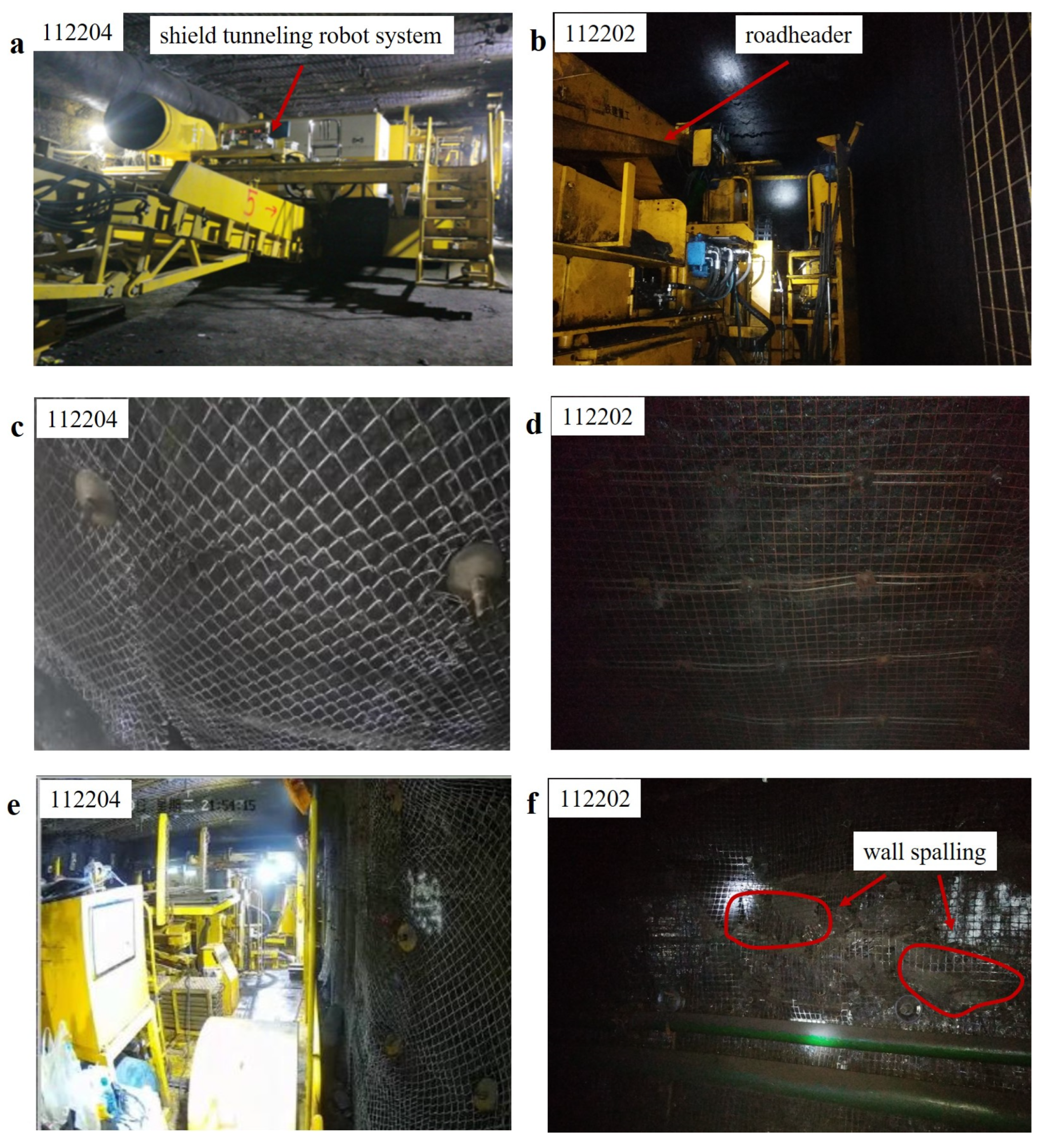
6. Field Application of Shield Tunneling Robot System

As shown in Figure 10, the shield tunneling robot system consists of a cutting system, temporary support system, permanent support system, ventilation and dust removal system, electro-hydraulic control platform, and transportation system. The cutting system is built into Temporary Support Robot I and connected to the drilling and bolting platform, while Temporary Support Robot II is linked to the electro-hydraulic control platform and transportation system. The entire system moves forward by the alternating push–pull actions of Temporary Support Robots I and II. The cutting system can cut up to 2 m in a single operation, establishing a maximum unsupported distance of 2 m (L1 = 2 m). The total length of Temporary Support Robots I and II is 10 m (L2 = 10 m), which defines the temporary support area as 10 m in length, ensuring that the combined length of the unsupported and temporary support areas does not exceed 18 m (L1 + L2 < 18 m) [99,100].
Tunnels 112202 and 112204 at the Xiao baodang Mining Company in Yulin, China, are two parallel tunnels with similar geological conditions. Tunnel 112202 was excavated using a road header, with permanent support installed immediately after excavation, resulting in slow tunneling speed. To prevent delays in subsequent operations, tunnel 112204 was excavated using the shield tunneling robot system. The first row of permanent support is positioned 12 m from the working face, enabling excavation and permanent support installation to operate in parallel with the assistance of the temporary support robots, significantly improving tunneling speed and addressing the severe wall spalling at the site, as shown in Figure 11.
The tunnel roof displacement is monitored using an electronic layer separation instrument, with a monitoring section interval of 100 m and measurements taken daily. As shown in Figure 12, after the operators became proficient in using the tunneling robot system, the daily advance reached up to 56 m, improving tunneling efficiency by nearly 40%. The roof strain between the 112202 and 112204 tunneling faces is quite similar. During the first half of the monitoring period, the roof strain at the 112204 tunneling face was even lower than that at the 112202 tunneling face. This is because the temporary support provides an active support force that exceeds that of rock bolts. Additionally, the roof displacement at the 112204 working face shows a more linear pattern, indicating that the temporary support did not repeatedly support with the roof during movement. This finding partially verifies that the temporary support indeed generates a support stress field in the surrounding rock of unsupported areas, and it also confirms the feasibility of the proposed method of long-distance temporary support following excavation.

7. Conclusions

In summary, to ensure reliable support of the surrounding rock and the reasonable setting of the unsupported distance during parallel operations of excavation and permanent support, this work proposed a temporary support stress distribution model. The research found that as height increases, the temporary support force initially increases and then decreases. Additionally, the results indicated that in the direction of excavation, the temporary support force remains relatively stable within a distance of 3 m but drops sharply beyond this threshold. The study on the evolution of roof strain in unsupported areas reveals a strong linear relationship between the unsupported distance and the optimal temporary support force. Under the action of temporary support, the maximum unsupported distance is 3 m, which is approximately 33% higher than the maximum unsupported distance of 2 m under permanent support. The inflection point in roof strain with changes in the length of the temporary support area occurs at 18 m from the tunnel face; therefore, the length of the temporary support area should not exceed 15 m. The on-site monitoring data largely indicate that temporary support can indeed generate a support stress field in the unsupported areas. The successful application of the shield tunneling robot system practically confirms that the method of long-distance temporary support following excavation is feasible. Moreover, it enables the parallel operation of permanent support and excavation, resulting in an almost 40% increase in tunneling efficiency. This work demonstrated that the stability of the surrounding rock in unsupported areas is closely related to the temporary support force, support length, and unsupported distance. This work provided a basis for the selection and design of temporary support equipment, control of the temporary support force, and reasonable setting of the unsupported distance. The rapid tunneling system is a complex system composed of multiple elements such as humans, machines, and the environment. Therefore, future research should focus on further exploring and optimizing these factors to enhance the stability of the surrounding rock and increase tunneling efficiency.

Author Contributions

H.Z.: Writing—review and editing, data curation, investigation, visualization. H.M.: Formal analysis, data curation, conceptualization. C.W.: Writing—review and editing, data curation, funding acquisition. Q.M.: Conceptualization, methodology, formal analysis, funding acquisition. X.X.: Formal analysis, Data curation, funding acquisition. All authors have read and agreed to the published version of the manuscript.

Funding

This research was funded by the National Natural Science Foundation of China, grant numbers 52374161 and 52174150; the Key Technologies Research and Development Program of China, grant numbers 2023YFC2907603; Key Research and Development Projects of Shaanxi Province, grant numbers 2023-LL-QY-03); Shaanxi Science and Technology Association, grant numbers 2023-JC-YB-331.

Institutional Review Board Statement

Not applicable.

Informed Consent Statement

Not applicable.

Data Availability Statement

The data presented in this study are available upon request from the corresponding author.

Conflicts of Interest

The authors declare no conflicts of interest.

References

  1. Zhou, P.; Jiang, Y.F.; Zhou, F.C.; Gong, L.; Qiu, W.G.; Yu, J.W. Stability Evaluation Method and Support Structure Optimization of Weak and Fractured Slate Tunnel. Rock Mech. Rock Eng. 2022, 55, 6425–6444. [Google Scholar] [CrossRef]
  2. Liu, B.; Wang, Y.X.; Zhao, G.Z.; Yang, B.; Wang, R.R.; Huang, D.X.; Xiang, B. Intelligent decision method for main control parameters of tunnel boring machine based on multi-objective optimization of excavation efficiency and cost. Tunn. Undergr. Space Technol. 2021, 116, 104054. [Google Scholar] [CrossRef]
  3. Hu, L. Study and application of temporary support technology for fully mechanized mine roadway heading. Coal Sci. Technol. 2008, 36, 9–11. [Google Scholar] [CrossRef]
  4. Guo, F.; Zhang, N.; Xie, Z.Z.; Han, C.L.; Zhang, C.H.; Yuan, Y.Y.; He, Z.; Liu, J.H. A Three-Dimensional Supporting Technology, Optimization and Inspiration from a Deep Coal Mine in China. Rock Mech. Rock Eng. 2023, 57, 655–677. [Google Scholar] [CrossRef]
  5. Wang, H.T.; Zhou, C.K.; Bi, Q.Q.; Zhu, H.; Ding, Z.W.; Zhang, C.C. Adaptive Modification of TBM Tunneling in Coal Mine Roadway and Disaster Control Technology for Complex Geological Conditions. Processes 2023, 11, 1389. [Google Scholar] [CrossRef]
  6. Huang, Q.X.; Liu, Y.W. Ultimate self-stable arch theory in roadway support. J. Min. Saf. Eng. 2014, 31, 354–358. [Google Scholar] [CrossRef]
  7. Wang, Q.; Pan, R.; Jiang, B.; Li, S.C.; He, M.C.; Sun, H.B.; Wang, L.; Qin, Q.; Yu, H.C.; Luan, Y.C. Study on failure mechanism of roadway with soft rock in deep coal mine and confined concrete support system. Eng. Fail. Anal. 2017, 81, 155–177. [Google Scholar] [CrossRef]
  8. Pongpanya, P.; Soysouvanh, V.; Sasaoka, T.; Shimada, H. Stability of Underground Coal Mine Roadway Excavated in Soft Rock Mass. Eur. J. Eng. Technol. Res. 2021, 6, 2619–26325. [Google Scholar] [CrossRef]
  9. Zheng, L.J.; Zuo, Y.J.; Hu, Y.F.; Wu, W. Deformation mechanism and support technology of deep and high-stress soft rock roadway. Adv. Civ. Eng. 2021, 2021, 6634299. [Google Scholar] [CrossRef]
  10. Wu, B.; Sun, W.T.; Cai, G.W.; Meng, G.W. Reliability analysis of shallow-buried tunnel construction adjacent to karst cave. Comput. Geotech. 2022, 145, 104673. [Google Scholar] [CrossRef]
  11. Wang, Q.; Jiang, B.; Pan, R.; Li, S.C.; He, M.C.; Sun, H.B.; Qin, Q.; Yu, H.C.; Luan, Y.C. Failure mechanism of surrounding rock with high stress and confined concrete support system. Int. J. Rock Mech. Min. Sci. 2018, 102, 89–100. [Google Scholar] [CrossRef]
  12. Xie, Z.Z.; Zhang, N.; Feng, X.W.; Liang, D.X.; Wei, Q.; Weng, M.Y. Investigation on the evolution and control of surrounding rock fracture under different supporting conditions in deep roadway during excavation period. Int. J. Rock Mech. Min. Sci. 2019, 123, 104122. [Google Scholar] [CrossRef]
  13. Wang, H.; Jiang, C.; Zheng, P.Q.; Li, N.; Zhan, Y.B. Deformation and failure mechanism of surrounding rocks in crossed-roadway and its support strategy. Eng. Fail. Anal. 2020, 116, 104743. [Google Scholar] [CrossRef]
  14. Zhai, M.H.; Zhang, D.F.; Hu, S.C.; Ma, C.Y.; Chen, B.; Wang, Z.P. Development of circular forward temporary support system for fully mechanized excavation roadway. Coal Mine Mach. 2023, 44, 58–60. [Google Scholar] [CrossRef]
  15. Seryakov, V.M.; Krasnovsky, A.A. Stress State of Support System in Temporary Roadway in Unstable Rock Mass. Dokl. Phys. 2022, 67, 600–603. [Google Scholar] [CrossRef]
  16. Wang, X.L.; Lai, J.X.; Garnes, R.S.; Luo, Y.B. Support System for Tunnelling in Squeezing Ground of Qingling-Daba Mountainous Area: A Case Study from Soft Rock Tunnels. Adv. Civ. Eng. 2019, 2019, 8682535. [Google Scholar] [CrossRef]
  17. Liu, J.S.; Cheng, F.M.; Guo, X.H.; Lu, Z.L.; Li, Z.X. Hydraulic system design of temporary support for fast excavation of top coal. IOP Conf. Ser. Earth Environ. Sci. 2021, 772, 012053. [Google Scholar] [CrossRef]
  18. Krauze, K.; Bołoz, Ł.; Mucha, K.; Wydro, T. The mechanized supporting system in tunnelling operations. Tunn. Undergr. Space Technol. 2021, 113, 103929. [Google Scholar] [CrossRef]
  19. Xue, G.H.; Guan, J.; Cheng, J.J.; Zhang, H.; Ji, W.L.; Jing, X.P.; Wu, M. Design of advance support for deep fully-mechanized heading roadway and its support performance analysis. Coal Sci. Technol. 2018, 46, 15–20. [Google Scholar] [CrossRef]
  20. Xie, M.; Liu, Z.X.; Lu, J.N.; Mao, J. Development of similar experimental prototype of the advanced support and the experimental study on its coupling mechanics with roof. J. China Coal Soc. 2017, 42, 1319–1324. [Google Scholar]
  21. Yang, D.H.; Ning, Z.X.; Lyu, Z.H.; Bai, X.T. Application and development on new type walking self moving advance temporary powered support. Coal Sci. Technol. 2015, 43, 112–115. [Google Scholar] [CrossRef]
  22. Zhan, J.W.; Yang, J.; Bian, W.H.; Zhao, R.D.; Dong, M.Q. Analytical study and engineering application of NPR prestressed bolt is anchored by mechanical-type anchorage and resin. Tunn. Undergr. Space Technol. 2024, 145, 105616. [Google Scholar] [CrossRef]
  23. Zhang, Y.H.; Li, L.P.; Fan, H.Y.; Chen, G.Q.; Liu, H.L.; Gao, J.Y.; Wang, M.X. An extended 3D discontinuous deformation analysis method considering bolt supports and its application in tunnels. Comput. Geotech. 2024, 169, 106219. [Google Scholar] [CrossRef]
  24. Silva, C.; Bernaud, D.; Real, M.; Maghous, S. Reliability analysis of bolt-supported tunnels regarded as homogenized structures. Int. J. Numer. Anal. Met. 2023, 47, 2531–2561. [Google Scholar] [CrossRef]
  25. Wang, J.; Liu, P.; He, M.C.; Tian, H.Z.; Gong, W.L. Mechanical Behaviour of a Deep Soft Rock Large Deformation Roadway Supported by NPR Bolts: A Case Study. Rock Mech. Rock Eng. 2023, 56, 8851–8867. [Google Scholar] [CrossRef]
  26. Sakhno, I.; Sakhno, S. Numerical Studies of Floor Heave Control in Deep Mining Roadways with Soft Rocks by the Rock Bolts Reinforcement Technology. Adv. Mater. Sci. Eng. 2023, 2023, 2756105. [Google Scholar] [CrossRef]
  27. Luo, S.Z.; Liang, W.Z. Optimization of roadway support schemes with likelihood-based MABAC method. Appl. Soft Comput. 2019, 79, 105887. [Google Scholar] [CrossRef]
  28. Huat, C.Y.; Armaghani, D.J.; Lai, S.H.; Rasekh, H.; He, X.Z. Simulation of Surface Settlement Induced by Parallel Mechanised Tunnelling. Sustainability 2023, 15, 13265. [Google Scholar] [CrossRef]
  29. Li, Z.; Xu, H.Y.; Wang, Z.J. Analytical Solution for Interaction between Tunnel Surrounding Rock and Supports in Red Sandstone Stratum. KSCE J. Civ. Eng. 2023, 27, 4993–5007. [Google Scholar] [CrossRef]
  30. Sun, Z.Y.; Zhang, D.L.; Fang, Q.; Dui, G.S.; Tai, Q.M.; Sun, F.W. Analysis of the interaction between tunnel support and surrounding rock considering pre-reinforcement. Tunn. Undergr. Space Technol. 2021, 115, 104074. [Google Scholar] [CrossRef]
  31. Zhou, P.; Zhou, F.C.; Lin, J.Y.; Li, J.Y.; Jiang, Y.F.; Wang, Z.J.; Yang, B. Decoupling Analysis of Interaction between Tunnel Surrounding Rock and Support in Xigeda Formation Strata. KSCE J. Civ. Eng. 2021, 25, 4897–4921. [Google Scholar] [CrossRef]
  32. Shan, R.L.; Wei, Y.H.; Wang, C.H.; Li, Z.L.; Li, Y.Z.; Liu, D.; Zhao, X.P. Research on the Failure Mechanism of Surrounding Rock in a Dynamic Pressure Roadway and Active and Passive Coordinated Support Technology. App. Sci. 2024, 14, 1858. [Google Scholar] [CrossRef]
  33. Wang, K.Z.; Xiong, Y.; Li, S.; Zhou, X.; Li, Z.K. Deformation Characteristics Analysis of Temporary Support in Unsymmetrical Loading Tunnel Excavation under Composite Support. Symmetry 2023, 15, 830. [Google Scholar] [CrossRef]
  34. Cheng, X.S.; Ding, K.; Liu, G.N.; Bu, Y.Y. Mechanical Properties of Super-large and Shallow-buried Loess Tunnel with the Prefabricated Temporary Support. Recent Pat. Eng. 2023, 18, 2024. [Google Scholar] [CrossRef]
  35. Xu, Z.J.; Li, C.; Cao, Y.; Tai, L.H.; Han, J. A case study on new high-strength temporary support technology of extremely soft coal seam roadway. Sci. Rep. 2023, 13, 21333. [Google Scholar] [CrossRef]
  36. Li, Z.H.; Hu, J.; Zhu, H.X.; Feng, J.L.; He, M.C. Numerical study on the CRLD cable–rock interaction under static pull-out loading using coupled DEM–FDM method. Acta Geotech. 2020, 15, 2137–2158. [Google Scholar] [CrossRef]
  37. Dai, L.P.; Pan, Y.S.; Wang, A.W. Study of the energy absorption performance of an axial splitting component for anchor bolts under static loading. Tunn. Undergr. Space Technol. 2018, 81, 176–186. [Google Scholar] [CrossRef]
  38. Zeng, Y.; Huang, B.; Zou, Y.; Bai, Y. Numerical Study on Static and Dynamic Load Response of Temporary Support System for Group Tunnels Excavation. Buildings 2022, 12, 1719. [Google Scholar] [CrossRef]
  39. Song, D.J.; Li, G.; Liu, J.S. Long-Distance and High-Efficiency Temporary Support Technology in Dynamic Pressure Bearing Area of Gob-Side Entry Retaining. Iran. J. Sci. Technol. Trans. Civ. Eng. 2024, 48, 3521–3533. [Google Scholar] [CrossRef]
  40. Zong, Q.; Lv, N.; Wang, H.B.; Duan, J.C. Numerical analysis on dynamic response and damage threshold characterization of deep rock mass under blasting excavation. Front. Mater. 2022, 11, 1329549. [Google Scholar] [CrossRef]
  41. Liu, X.S.; Song, S.L.; Tan, Y.L.; Fan, D.Y.; Ning, J.G.; Li, X.B.; Yin, Y. Similar simulation study on the deformation and failure of surrounding rock of a large section chamber group under dynamic loading. Int. J. Min. Sci. Technol. 2021, 31, 495–505. [Google Scholar] [CrossRef]
  42. Kang, H.P. Analysis on types and interaction of stress fields in underground coal mines. J. China Coal Soc. 2008, 33, 1329–1335. [Google Scholar] [CrossRef]
  43. Li, J.Z.; Kang, H.P.; Gao, F.Q.; Lou, J.F. Analysis of bolt support stress field and bolt support effect under in-situ stress field. J. China Coal Soc. 2020, 45, 99–109. [Google Scholar] [CrossRef]
  44. Tang, Z.; Wu, Z.W.; Jia, D.W.; Lv, J.G. The Distribution Law of Ground Stress Field in Yingcheng Coal Mine Based on Rhino Surface Modeling. Processes 2024, 12, 668. [Google Scholar] [CrossRef]
  45. Zhao, Z.H.; Tan, T.L.; Chen, S.J.; Ma, Q.; Gao, X.J. Theoretical analyses of stress field in surrounding rocks of weakly consolidated tunnel in a high-humidity deep environment. Int. J. Rock Mech. Min. 2019, 122, 104064. [Google Scholar] [CrossRef]
  46. Zhu, G.Q.; Li, S.J.; Li, C.D.; Liu, G.; Zhou, Y.Y. Physical Model Study on Brittle Failure of Pressurized Deep Tunnel with Support System. Rock Mech. Rock Eng. 2023, 56, 9013–9033. [Google Scholar] [CrossRef]
  47. Mitri, H.S.; Hassani, F.P. Nonlinear finite element analysis of mine roadway arch support systems. Eng. Fract. Mech. 1988, 31, 161–170. [Google Scholar] [CrossRef]
  48. Guo, L.J.; Tao, Z.G.; He, M.C.; Coli, M. Excavation compensation and bolt support for a deep mine drift. J. Rock Mech. Geotech. Eng. 2024, 16, 3206–3220. [Google Scholar] [CrossRef]
  49. Wu, S.; Shi, C.; Zhang, C.; Zhang, Y.P.; Li, W.Y. Analytical Solution for the Stress Field in Surrounding Rock of a Near-Fault Tunnel Considering Tectonic Stress Boundary Conditions. Rock Mech. Rock Eng. 2024, 57, 7013–7031. [Google Scholar] [CrossRef]
  50. Luo, Z.W.; Zhang, R.; Li, R.; Zheng, L.J.; Zhang, Z.L.; Zhang, Z.T.; Xie, J.; Zhang, L.B. Analytical Solution and Factors Influencing the Tunnel Plastic Zone under a Nonuniform Stress Field. Ksce J. Civ. Eng. 2024, 28, 3016–3032. [Google Scholar] [CrossRef]
  51. Gu, S.C.; Wang, P.; Yang, C.F. Mechanical characteristics and stability analysis of surrounding rock reinforcement in rectangular roadway. Sci. Rep. 2022, 12, 22234. [Google Scholar] [CrossRef] [PubMed]
  52. Wang, Q.; Xu, S.; Jiang, B.; Zhang, C.; Sun, Z.; Liu, J.X.; Jiao, C.L. Development of multi-functional anchorage support dynamic-static coupling performance test system and its application. Int. J. Min. Sci. Technol. 2024, 34, 339–349. [Google Scholar] [CrossRef]
  53. Bednarek, Ł.; Małkowski, P.; Niedbalski, Z.; Mucha, K. Steel Arch and Rock Bolt Support in Terms of the Gateroad Stability Maintaining behind the Longwall Face. Appl. Sci. 2024, 14, 3594. [Google Scholar] [CrossRef]
  54. Majcherczyk, T.; Niedbalski, Z.; Małkowski, P.; Bednarek, ł. Analysis of Yielding Steel Arch Support with Rock Bolts in Mine Roadways Stability Aspect. Acta Mech. Slov. 2014, 18, 38–44. [Google Scholar] [CrossRef]
  55. Chen, Y.; Bai, J.B.; Yan, S.; Hao, S.P.; Dao, V.D. A method for computing unsupported roof distance in roadway advancement and its in-situ application. Int. J. Min. Sci. Technol. 2016, 26, 551–556. [Google Scholar] [CrossRef]
  56. Zhang, J.; Gao, S.S.; He, Y.F.; Yang, T.; Wang, B.; Wang, L.; Pang, H.B.; Peng, B. Study of the roof deformation characteristics of roadway excavation face and unsupported roof distance. Adv. Civ. Eng. 2023, 2023, 9916513. [Google Scholar] [CrossRef]
  57. Sen, Y.; Hua, X.Z.; Liu, X.; Li, C. Analysis of Stability Factors of Roadway Roof and Determination of Unsupported Roof Distance. Adv. Civ. Eng. 2021, 2021, 2271257. [Google Scholar] [CrossRef]
  58. Zhou, Z.H.; Xie, Q.M.; Chen, Z.Q.; Yao, Y.K.; Meng, W. Failure mechanism and stability identification of surrounding rock for soft-rock tunnels using long-footage rapid excavation method. Eng. Fail. Anal. 2024, 158, 108038. [Google Scholar] [CrossRef]
  59. Kumar, M.; Jyoti, D.; Nirmal, K.; Rana, B.; Subhashish, T.; Angad, K. Assessment of roof convergence during driving roadways in underground coal mines by continuous miner. Int. J. Rock Mech. Min. Sci. 2018, 108, 169–178. [Google Scholar] [CrossRef]
  60. Yan, J.Z.; Su, K.; Zhu, H.Z.; Zhong, D.Q.; He, G.W. Installation time of an initial support for tunnel excavation upon the safety factors of surrounding rock. Appl. Sci. 2020, 10, 5653. [Google Scholar] [CrossRef]
  61. Zhang, K.; Li, Y.X.; Zhong, D.H.; Meng, X.; Huang, Q.X.; Xu, Y.; Chen, H.Y.; Ma, Y.; Zhang, D.S.; Huang, L.S.; et al. Research and experimental verification of mechanical characteristics of advanced hydraulic support group-anchor coupling support. Chin J. Rock Mech. Eng. 2021, 40, 1428–1443. [Google Scholar]
  62. Zhang, K.; Li, Y.X.; Feng, L.; Meng, X.J.; Zhong, D.H.; Huang, L.S. Roof deformation characteristics and experimental verification of advanced coupling support system supporting roadway. Energy Sci. Eng. 2022, 10, 2397–2419. [Google Scholar] [CrossRef]
  63. Zhao, B.C.; Wang, J.B. Study on interval rupture mechanism and support optimization of layered roof. Eng. Fail. Anal. 2022, 141, 106690. [Google Scholar] [CrossRef]
  64. Bi, Y.W.; Wang, M.X.; Wu, C.; Huang, Y.C. Surrounding rock stability in unsupported roof area and rapid heading technique for deep arch coal roadways under goaf. Minerals 2022, 12, 1329. [Google Scholar] [CrossRef]
  65. Yang, J.J.; Ge, S.R.; Wang, F.Y.; Luo, W.J.; Zhang, Y.C.; Hu, X.T.; Zhu, T.; Wu, M. Parallel tunneling: Intelligent control and key technologies for tunneling, supporting and anchoring based on ACP theory. J. China Coal Soc. 2021, 46, 2100–2111. [Google Scholar]
  66. Wang, H.; Wang, J.L.; Zhang, X.F. Theory and technology of efficient roadway advance with driving and bolting integration. J. China Coal Soc. 2020, 45, 2021–2030. [Google Scholar]
  67. Yu, B.B.; Li, Q.; Zhao, T.D. Deformation extent prediction of roadway roof during non-support period using support vector regression combined with swarm intelligent bionic optimization algorithms. Tunn. Undergr. Space Technol. 2024, 145, 105585. [Google Scholar] [CrossRef]
  68. Yao, Y.Q.; Wang, H.Z.; Liu, H.L.; Li, G.D. Deformation Characteristics and Destabilization Mechanisms of the Surrounding Rock of Near-Vertical Coal–Rock Interbedded Roadway. Appl. Sci. 2023, 13, 8397. [Google Scholar] [CrossRef]
  69. Shang, Y.Q.; Kong, D.Z.; Pu, S.J.; Xiong, Y.; Li, Q.; Cheng, Z.B. Study on Failure Characteristics and Control Technology of Roadway Surrounding Rock under Repeated Mining in Close-Distance Coal Seam. Mathematics 2022, 10, 2166. [Google Scholar] [CrossRef]
  70. Wu, Y.H.; Liu, X.S.; Tan, Y.L.; Wang, W.; Li, X.B.; Wang, X. Mechanism of bolt breakage in deep mining roadway under dynamic load and advanced strengthening support technology. Eng. Fail. Anal. 2024, 161, 108252. [Google Scholar] [CrossRef]
  71. Li, D.Q. A new analytical model for stress distribution in the rock bolt under axial loading. Int. J. Rock Mech. Min. 2024, 176, 105690. [Google Scholar] [CrossRef]
  72. Xie, S.R.; Li, H.; Chen, D.D.; Feng, S.H.; Yang, J.H.; Ma, X.; Jiang, Z.S.; Xing, S.K. Research on the Control Technology and Key Parameters of External Anchor-Internal Unloading of Surrounding Rock During Gob-Side Entry Driving Under Severe Mining of 1000-m-Deep Mine. Rock Mech. Rock Eng. 2024, 54, 2913–2932. [Google Scholar] [CrossRef]
  73. Fu, M.X.; Liu, S.W.; Huang, S.S.; Jia, H.S. Resin Flow Characteristics and Anchoring Performance of Resin-Anchored Bolts in Soft and Broken Surrounding Rock. Rock Mech. Rock Eng. 2023, 57, 1579–1601. [Google Scholar] [CrossRef]
  74. Greig, K.; John, H. Performance of Conventional and Energy-Absorbing Self-Drilling Hollow Core Rockbolts Under Controlled Laboratory Conditions. Rock Mech. Rock Eng. 2023, 56, 4363–4378. [Google Scholar]
  75. Lei, M.Y.; Zhang, X.H.; Dong, Z.; Wan, J.C.; Zhang, C.; Zhang, G.M. Locating Anchor Drilling Holes Based on Binocular Vision in Coal Mine Roadways. Mathematics 2023, 11, 4365. [Google Scholar] [CrossRef]
  76. Sun, C.; Chen, D.X.; Wang, L.G.; Wu, L. Quantitative evaluation of the constraint effect and stability of tunnel lining support. Tunn. Undergr. Space Technol. 2021, 112, 103920. [Google Scholar] [CrossRef]
  77. Wang, R.J.; Li, C.; Xu, J.H.; Pan, L.J. Development and verification of large deformation model considering stiffness deterioration and shear dilation effect in FLAC3D. Int. J. Min. Sci. Technol. 2018, 28, 959–967. [Google Scholar] [CrossRef]
  78. Pan, W.P.; Li, H.B.; Hua, X.Z.; Liu, B.; Li, C. Research on grouting reinforcement technology of fault crossing roadway in fully mechanized mining face with large dip angle. Bull. Eng. Geol. Environ. 2024, 83, 216. [Google Scholar] [CrossRef]
  79. Xiao, T.M.; He, M.C.; Qiao, Y.F.; Cai, W.Q.; Jiang, Y.J.; Zhu, H.H. A novel implementation method of GZZ-based constitutive model into FLAC3D. Tunn. Undergr. Space Technol. 2024, 145, 105601. [Google Scholar] [CrossRef]
  80. Wang, D.J.; Li, R.; Cheng, J.M.; Zheng, W.X.; Shen, Y.; Zhao, S.H.; Wu, M. Research on the calculation model and control method of initial supporting force for temporary support in the underground excavation roadway of coal mine. Axioms 2023, 12, 948. [Google Scholar] [CrossRef]
  81. Jin, H.W.; Huang, S.Y.; Zhou, J.; Ma, S.; Xiao, Q. Study on Stress Field Topology Characterization and Stability of Roadway Surrounding Rock. Arab. J. Geosci. 2022, 15, 484. [Google Scholar] [CrossRef]
  82. Wang, F.Y.; Mao, K.M.; Li, B. Prediction of residual stress fields from surface stress measurements. Int. J. Mech. Sci. 2018, 140, 68–82. [Google Scholar] [CrossRef]
  83. Fan, T.R.; Wang, J.C.; Wang, Z.H. Analytical Solutions of Elastic Complex Variables for Tunnels with Complicated Shapes Under Geostress Field. Rock Mech. Rock Eng. 2024, 57, 4973–4993. [Google Scholar] [CrossRef]
  84. Zhao, H.H.; Su, H.J.; Qin, X.F.; Zhang, K.; Jiang, Y.; Wang, W.B. Experiment and Numerical Simulation of Strength and Stress Distribution Behaviors of Anchored Rock Mass in a Roadway. Geofluids 2023, 2023, 93311206. [Google Scholar] [CrossRef]
  85. Yang, J.W.; Lin, J.; Jiang, P.F. True Triaxial Test and Research into Bolting Support Compensation Stresses for Coal Roadways at Different Depths. Processes 2023, 11, 3071. [Google Scholar] [CrossRef]
  86. Zhang, K.J.; Zhao, X.; Zhang, Z.Q. Influences of tunnelling parameters in tunnel boring machine on stress and displacement characteristics of surrounding rocks. Tunn. Undergr. Space Technol. 2023, 137, 105129. [Google Scholar] [CrossRef]
  87. Wang, T.Y.; Liu, H.N.; Kang, M.L.; Zhao, B.C.; Shen, J.X.; Li, Y.C.; Yang, Y.D. Study on the Synergistic Effect of Primary Support and Surrounding Rock of Large Buried Depth Tunnel in Soft and Fractured Strata. Appl. Sci. 2024, 14, 2028. [Google Scholar] [CrossRef]
  88. Wu, X.Y.; Wang, S.; Gao, E.P.; Chang, L.; Ji, C.X.; Ma, S.J.; Li, T. Failure mechanism and stability control of surrounding rock in mining roadway with gentle slope and close distance. Eng. Fail. Anal. 2023, 152, 107489. [Google Scholar] [CrossRef]
  89. Li, G.J.; Wang, X.Y.; Bai, J.B.; Wu, B.W.; Wu, W.D. Research on the failure mechanism and control technology of surrounding rock in gob-side entry driving under unstable overlying strata. Eng. Fail. Anal. 2022, 138, 106361. [Google Scholar] [CrossRef]
  90. Zhang, Z.Q.; Chen, F.F.; He, M.M.; Wang, H. An Analytical Calculation Method for Displacement Criterion on Tunnel Surrounding Rock Mass Stability. Adv. Civ. Eng. 2022, 2022, 2493968. [Google Scholar] [CrossRef]
  91. Sun, X.M.; Wang, L.; Cui, L.; Zhang, Y.; Jiang, M. Experimental investigation of biaxial compressive mechanical property of NPR anchored rock with different preload forces. Tunn. Undergr. Space Technol. 2024, 146, 105621. [Google Scholar] [CrossRef]
  92. Sun, X.; Cheng, J.Y.; Wan, Z.J.; Lv, J.K.; Liu, K.C.; Gao, K.D. Analysis of the Support Failure Mechanism Caused by Bolt Pre-Tightening Force Loss. Processes 2024, 12, 113. [Google Scholar] [CrossRef]
  93. Sun, X.M.; Cui, L.; Zhang, Y.; Wang, L.; Jiang, M. Strength characteristics of rock anchored by NPR bolt with different preloads. J. Mt. Sci. Engl. 2023, 20, 834–844. [Google Scholar] [CrossRef]
  94. Chu, X.W.; Wu, Y.Z.; Wu, Z.G.; Hao, D.Y.; Feng, Y.L.; Li, W.Z.; Meng, X.Z. Characteristics of roof deformation in excavating face and determination method of reasonable non-support distance. J. Min. Saf. Eng. 2020, 37, 908–917. [Google Scholar]
  95. Su, C.; Li, P.; Gong, P.L.; Liu, C. Multifactor analysis of roof deformation and reasonable determination of the unsupported distance of a coal roadway heading face based on response surface method. Energy Sci. Eng. 2023, 11, 2395–2407. [Google Scholar] [CrossRef]
  96. Wu, K.; Wang, Y.Z.; Zheng, X.M.; Zhao, N.N. A better understanding of tunnel deformable supports: From analytical model to engineering application. Arch. Civ. Mech. Eng. 2024, 24, 114. [Google Scholar] [CrossRef]
  97. Ding, S.H.; Bai, J.D.; Han, J.L.; Wang, H.X.; Ma, F. Mechanical Characteristics Analysis and Structural Optimization of Key Component of Self-Moving Temporary Support. Appl. Sci. 2022, 12, 10745. [Google Scholar] [CrossRef]
  98. Chen, J.S.; Hu, C.J.; Ai, Q.C.; Yu, C.G. Design and research of hanging robot support platform in tunneling working face. Coal Mine Mach. 2022, 43, 1–4. [Google Scholar] [CrossRef]
  99. Ma, H.W.; Wang, P.; Wang, S.B.; Mao, Q.H.; Shi, Z.W.; XIA, J.; Yang, Z.; Xue, X.S.; Wang, C.W. Intelligent parallel cooperative control method of coal mine excavation robot system. J. China Coal Soc. 2021, 46, 2057–2067. [Google Scholar] [CrossRef]
  100. Ma, H.W.; Wang, S.B.; Mao, Q.H.; Shi, Z.W.; Zhang, X.H.; Yang, Z.; Cao, X.G.; Xue, X.S.; Xia, J.; Wang, C.W. Key common technology of intelligent heading in coal mine roadway. J. China Coal Soc. 2021, 46, 310–320. [Google Scholar]
Figure 1. Relationship between tunneling system and surrounding rock (a—unexcavated area; b—unsupported area; c—temporary support area; d—permanent support area; 1—excavating system; 2—temporary support system; 3—anchor drilling system;).
Applsci 14 11420 g001
Figure 2. Temporary support stress distribution model.
Applsci 14 11420 g002
Figure 3. Stress change regulation along excavation direction (a) and height direction (b) of the roadway.
Applsci 14 11420 g003
Figure 4. Stress nephogram at different heights from the roof.
Applsci 14 11420 g004
Figure 5. Comparison of stress curves at different heights from the roof.
Applsci 14 11420 g005
Figure 6. Influence of different temporary supporting forces on different empty roof spacing.
Applsci 14 11420 g006
Figure 7. Linear fitting relationship.
Applsci 14 11420 g007
Figure 8. Roof displacements conditions with different unsupported distance.
Applsci 14 11420 g008
Figure 9. Roof displacements under different temporary support lengths and unsupported distances.
Applsci 14 11420 g009
Figure 10. Relationship between robot system and surrounding rock (a—unexcavated area; b—unsupported area; c—temporary support area; d—permanent support area; 1—excavating robot; 2—temporary support robot I; 3—temporary support robot II; 4—anchor drilling platform; 5—electro-hydraulic control platform; 6—ventilation and transportation system).
Applsci 14 11420 g010
Figure 11. Tunneling face conditions. (a) Shield tunneling robot system. (b) Road header. (c) Tunnel 112204 face roof support condition. (d) Tunnel 112202 face roof support condition. (e) Tunnel 112204 face sidewall support conditions. (f) Tunnel 112202 face sidewall support conditions.
Applsci 14 11420 g011
Figure 12. On-site monitoring data. (a) Excavation distance monitoring. (b) Roof strain monitoring.
Applsci 14 11420 g012
Table 1. Simulation parameter.
SimulationArea of Section (m2)L1
(m)
L2
(m)
L3
(m)
F
(MPa)
Density
Kg m−3
Shear
(MPa)
Bulk
(MPa)
Tension
(MPa)
Cohesion
(MPa)
Friction
(MPa)
A6 × 5501001400600040000.4225
B6 × 5551061400600040000.4225
Disclaimer/Publisher’s Note: The statements, opinions and data contained in all publications are solely those of the individual author(s) and contributor(s) and not of MDPI and/or the editor(s). MDPI and/or the editor(s) disclaim responsibility for any injury to people or property resulting from any ideas, methods, instructions or products referred to in the content.

