Abstract
The article describes the application of a vehicle simulation model to assess the driving hazards that arise due to changes in the tyre–road adhesion during a lane change. An experimentally verified vehicle dynamics model was used. The typical single lane change maneuver, performed on dry concrete, wet concrete, and ice-covered roads, was simulated for three vehicle speeds. The disturbance was introduced as a changed tyre–road adhesion on the target lane. Typical sinusoidal (one-period) input was applied to the steering wheel. Adhesion change may lead to an accident when considering the driver’s reaction time. An original control algorithm has been built. It is the driver assistance system with a double PID controller of the steering wheel angle. The system parameters were determined based on the principles recommended in the automatic control engineering monographs. The controller fulfils its tasks for motion at very high speeds on a homogeneous road surface and for the case where the tyre–road adhesion is changed during a maneuver. Thanks to this, the threat can be avoided.
1. Introduction
Modern motor vehicles are being equipped with various driver assistance systems: Anti-lock Brake Systems (ABS), Acceleration Slip Regulation or Traction Control Systems (ASR-TCS), Electronic Stability Programs (ESP), Electronic Brake Distribution (EBD), Brake Assist Systems (BAS to shorten the vehicle response time), Adaptive Cruise Control (ACC to keep a safe distance to the frontward vehicle moving on the same road lane), Lane Departure Warning systems (LDW), etc. The vehicles with a high autonomization level (Level 4 and Level 5, according to the SAE classification [1]) can be driven almost without driver’s participation.
The road accident risk situations must be defined for the driver training process. Also, in the development process of driver assistance systems, it is important to include the scenarios in which the hazards are identified.
In publications [2,3,4,5], the authors highlight the importance of the lane change maneuver as the one that poses a great hazard. The collisions resulting from it are accountable for one-tenth of all the traffic delays caused by accidents and often lead to traffic jams [5,6]. The course of such maneuvers was examined in real conditions [3], by simulation methods [5], using car driving simulators [2,4].
In publications [6,7,8,9,10,11,12,13] (and many others), the introduction of automatic control systems modeling driver’s actions or assisting the driver during the lane change maneuver has been proposed.
In publication [14], the author unequivocally points to the “evident impact of the road surface and shoulders’ condition on the traffic safety”, including “the tyre–road adhesion conditions” and the surface irregularities (ruts, folds, humps). The problem of modeling the straight-line braking with a possible lane change when the driver spots a sudden change in the tyre–road adhesion has been discussed and the process has been modeled in [11]. The simulation represented the pre-accident situation rather than the change in the vehicle behaviour during a normal lane change. A similar problem (but without an analysis of the impact of the tyre–road adhesion) was addressed in [15]. Publication [16] covered the examination of a PID controller within the scope of per-forming a double lane change on a homogeneous road surface. In [8], a collision avoidance assistance system was proposed, including lane changing as a defensive action. The work [17] reviews a two-axle autonomous vehicle’s (AV) control methods (PID, MPC, SMC) to drive according to a given trajectory. An essential aspect of this work is to pay attention to the vehicle’s motion on a low-friction surface. The examples focused on controlling the steering wheel angle will be discussed hereafter.
This publication is to show the real threat that may arise in the road traffic from changes in the road surface condition, if the changes are encountered when the vehicle is driven without any influence of other vehicles or other road users. The single lane change on a straight road section has been described. Many simulations of the motion of a medium-class passenger car were carried out for a few typical speed values and different road surface conditions; the quantities that warn of the potential collision situation in question were pointed out when any intervention of the driver or the assistance systems is necessary.
An algorithm has been proposed for the operation of the assistance system that is to perform the maneuvers of this kind in a safe way when the driver cannot avoid the danger of lane or road departure.
The structure of the paper is organized as follows: Section 2 (Materials and Methods) presents a synthetic description of the vehicle simulation model and the reference trajectory model for the assistance system, while Section 3 (Scope and Parameters of the Tests) presents assumptions for the scope of calculations. The next section, Section 4 (Results and Discussion), presents the calculation results for the vehicle without the assistance system, followed by the model of the proposed assistance system and the results after its application, along with the analysis. Section 5 (Conclusions) summarises the authors’ most important observations on the results.
2. Materials and Methods
2.1. The Vehicle Under Test and Its Representative Model
The vehicle used for the tests was a KIA Ceed SW motor car (Kia Corporation, Žilina, Slovakia). The simulation model representing this vehicle (Figure 1), also shown in [18,19,20], consists of nine mass elements, i.e., car body solid, four material points O1, O2, O3, and O4 (assumed as the points of concentration of car’s “unsprung masses”), and four rotating solids (wheels). The following coordinate systems have been adopted (see also works [21,22,23,24] with a similar approach to the subject):
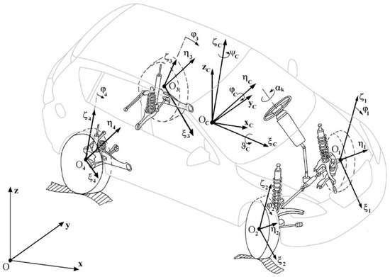
Figure 1.
The model of a two-axle car with independent front and rear wheel suspension systems. Additionally, adopted coordinate systems are shown [18].
- Oxyz—a system attached to the road (horizontal axes Ox and Oy and vertical axis Oz pointing upwards);
- OCxCyCzC—a system with axes parallel to the Ox, Oy, and Oz axes (respectively), with its origin situated at the car body centre of mass Oc;
- coordinate systems fixed to model’s rigid bodies, i.e., body solid (OCξCηCζC) and four road wheels (O1ξ1η1ζ1, O2ξ2η2ζ2, O3ξ3η3ζ3, O4ξ4η4ζ4);
- extra systems that define the transformation matrices.
The translational motion is described using the positions of the centres of mass (OC, O1, O2, O3, O4) of the said solids. The axes Oiξi, Oiηi, Oiζi (i = C, 1, 2, 3, 4) are treated as the principal central axes of inertia of the corresponding rigid bodies.
To describe the spherical motion of the car body solid around the OC centre, the “aircraft angles”, also referred to as “quasi-Euler angles”, have been used (see also works [21,22,23,24] with a similar approach to the subject):
- yaw angle ψC (rotation around the OCζC axis);
- pitch angle φC (rotation around the OCηC axis);
- roll angle ϑC (rotation around the OCξC axis).
The purpose of introducing the OCxCyCzC system was to show body’s c.g. and the reference system that enables the definition of body angular motion coordinates (“quasi-Euler angles”): ψC, φC, ϑC.
The axes of rotations are treated as the principal central axes of inertia. The Lagrange equations of the second kind have been applied to derive equations of motion. Fourteen generalized coordinates were adopted (qi; i = 1, 2, …14):
- q1 = xOC, q2 = yOC, q3 = zOC—the position of the centre of mass of the car body solid (OC) in the inertial reference system Oxyz;
- q4 = ψC, q5 = φC, q6 = ϑC—the spherical motion of the car body solid around its centre of mass OC (yaw, pitch, and roll angle, respectively);
- q7 = ζCO1, q8 = ζCO2, q9 = ζCO3, q10 = ζCO4—the motion of points O1, O2, O3, O4 relative to the car body solid in the direction of axis OCζC of the OCξCηCζC coordinate system;
- q11 = φ1, q12 = φ2, q13 = φ3, q14 = φ4—wheel angles of rotation.
The model describes steering system flexibility and the steered wheels parameters: camber, caster, kingpin, and toe-in. The HSRI-UMTRI tyre–road contact model [25,26] has been adopted together with the IPG-Tire model of transient states of tyres [23,27]. The presented model has been successfully experimentally verified for typical vehicle maneuvers: steady-state cornering, step input on the steering wheel, double lane change, single lane change, straight-line braking [28,29,30,31]. So, it also considered the single lane change maneuvers.
2.2. The Road on Which the Lane Change Maneuver Is Carried Out
Figure 2 shows a straight section of a two-lane road, where the right and left lanes, separated from each other by a broken line, are labelled R and L, respectively. Oxyz is an inertial reference system, attached to the road. At the beginning of the single lane change maneuver under analysis, the vehicle under test is moving straightforward in the centre of the right lane.
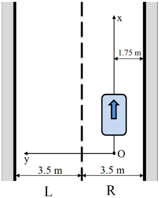
Figure 2.
Straight section of a two-lane road, where the right and left lanes, separated from each other by a broken line, are labelled R and L, respectively (the latter being intended for the oncoming traffic). Oxyz is an inertial reference system, attached to the road.
2.3. Model of the Desired Vehicle Trajectory During the Single Lane Change Maneuver
In publications [32,33,34,35], the following models to describe the vehicle trajectory (represented by the trajectory of vehicle’s centre of mass) during the single lane change maneuver (1LCM) have been proposed: model 1 by Papić et al. [33] and Bascunan [32], model 2 by Nelson [35], model 3 by Zellner [34], model 4 by Fett, Frick and Daily [33], and model 5 by Chee [33]. They have trigonometrical forms based on sin/cos functions or circular/polynomial functions. As a result, they show very similar shapes. Authors of this paper decided to apply model 3 by Zellner [34] presented in the paper by Papić et al. [33]—see Equation (1). The reason was the closest (in the mean square sense) distance of this analytical description to the motion trajectory of the simulated vehicle during the lane change maneuver (1LCM).
where x—longitudinal vehicle displacement, [m]; y—lateral vehicle displacement, [m]; H—planned maximum lateral vehicle displacement, [m]; Lm—longitudinal vehicle displacement during the performing of the single lane change maneuver, [m].
In this case, the vehicle yaw angle during the maneuver can be expressed as below:
If the vehicle speed (v [m/s] or V [km/h]) is constant during the 1LCM (single lane change maneuver), then Equations (1) and (2) may be transformed into the time domain t [s] thanks to the relation:
The parameter of the 1LCM is the maneuver duration time T [s]:
The 1LCM duration time T is estimated based on experimental tests. In publication [3], this time is 2–7 s. In [36], its full range, i.e., 1–13.3 s, is considered, but particular attention is paid (based on a statistical analysis) to the range of 2.54–6.28 s. In [37], the range of 1.0–2.6 s is covered by the analysis. In the normative act withdrawn by ISO [28], the value of 2 s was adopted. In the simulation tests reported herein, the authors adopted a value of T = 3 s, thus emphasizing the low dynamics of the maneuver under analysis, which corresponds to the normal smooth driving on a straight road section. This is usually connected with an identical steering wheel input duration time Tw = 3 s (a single period of the sinusoidal input). In [36], attention is directed to the fact that the 1LCM duration time T does not depend on the vehicle speed.
The final lateral vehicle displacement H during the 1LCM depends on the lane width. In the normative act [38], values from the range of 2.5–3.75 m were specified; actually, the value of H = 3.5 m often occurs on higher-class roads and this value was adopted in the simulation tests reported herein.
In [39], the range of the maximums of the lateral acceleration values recorded during the overtaking maneuvers in the real traffic has been specified as 0.3–3.2 m/s2. The averaged values of these maximums were in the range of 0.99–2.01 m/s2.
2.4. Model of the Driver Assistance System
The model of the driver assistance system proposed, together with a review of similar models found in the literature, will be presented in Section 4.4, where the results of the tests carried out within this scope will be discussed.
3. Scope and Parameters of the Tests
The vehicle data adopted for the tests corresponded to a fully loaded KIA Ceed car (1890 kg) with “symmetrical” specifications, i.e., a car where its centre of mass is situated in the car symmetry plane and the parameters of setting the left and right steerable wheels are identical to each other.
The scope of the tests included the following, in succession:
- simulation tests of the single lane change maneuver (1LCM) for the vehicle with no driver assistance system, on homogeneous and heterogeneous road surfaces;
- verification of the vehicle trajectory model for the driver assistance system;
- simulation tests of the single lane change maneuver (1LCM) for the vehicle with a driver assistance system, on homogeneous and heterogeneous road surface.
The simulation tests were carried out for three initial vehicle speeds, i.e., 50, 90, and 140 km/h (the last is the speed limit on motorways in Poland). These values were adopted as the typical speed limits that occur in the road traffic. Initially, the vehicle was moving in the centre of the right lane (R) and then it changed the lane to the left one (L) (see Figure 2).
Three types of the road surface condition were adopted for the tests: dry concrete, wet concrete, and ice. In the case of homogeneous road surface, the surface condition was identical for both the left (L) and right (R) lanes (see Figure 2). For the case with the heterogeneous road surface (also referred to as being of the μ split type), six combinations were considered, as shown in Table 1.

Table 1.
The road lane surface combinations adopted.
The maneuver was forced by changing the steering wheel angle. For the vehicle with no driver assistance system, the input to be applied was adopted as a single period of a sinusoid with a duration time of Tw = 3 s. The amplitude of changes in the steering wheel angle for the homogeneous road surface was selected by iteration so that the lateral vehicle displacement (in the y direction, see Figure 2) was about 3.5 m. For the heterogeneous road surface, it was assumed that the driver performed the maneuver by applying an input identical (as regards its period and amplitude) to that used for the surface of the right lane (R) in the case of the homogeneous road surface (dry concrete, wet concrete, or ice), keeping this input unchanged in spite of entering the other lane, i.e., the left one (L) with a different surface.
For the vehicle with a driver assistance system, the input applied to the steering wheel was as determined by the system.
As mentioned, the HSRI-UMTRI model [25,26], together with the IPG-Tire model of transient states of tyres [23,27], was used for the description of the forces and moments of forces. Table 2 shows the values of the main coefficients of the model, which is also referred to as the Dugoff–Fancher–Segel model [25,26], for the three road surface types adopted. The meaning of the symbols used in the table are as follows: μ0 is the maximum value of the tyre–road adhesion coefficient (for v being close to zero), kv defines the dependence of the tyre–road adhesion coefficient on the slip velocity, cx is the kinematic circumferential stiffness of the tyre, cy is the cornering stiffness of the tyre, and kp is the lateral tyre stiffness.
Table 2.
The adopted values of the main coefficients of the Dugoff–Fencher–Segel model of the forces and moment in the tyre–road contact zone.
The characteristics of the longitudinal and lateral tangential unit forces and of the aligning moment in the tyre–road contact zone for the vehicle speeds under consideration have been illustrated in Figure 3.
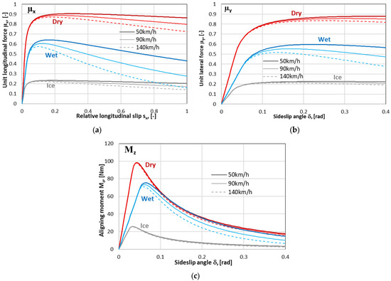
Figure 3.
Characteristics of tyre–road contact: (a) longitudinal unit force; (b) lateral unit force; (c) aligning moment.
4. Results and Discussion
4.1. The 1LCM for the Vehicle with No Driver Assistance System, for the Homogeneous Road Surface
Figure 4 shows the results of the simulation of the lane change maneuver for a vehicle with no driver assistance system on a homogeneous road surface for three surface types (dry, wet, ice) and three vehicle speeds (50, 90, and 140 km/h) in the form of time histories of the input applied, i.e., steering wheel angle αk, and of the response obtained, i.e., lateral displacement of vehicle’s centre of mass (yOc) and time derivative of the displacement (yOcPrim ≡ dyOc/dt).
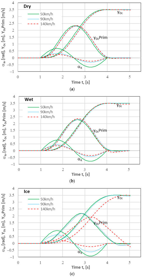
Figure 4.
Lane change (1LCM) simulation results. Road surface: (a) dry concrete, (b) wet concrete, (c) ice. Notation: αk—input, i.e., steering wheel angle; yOc—lateral displacement of vehicle’s centre of mass OC; yOcPrim—lateral velocity of vehicle’s centre of mass OC.
Satisfactory results were obtained for all three road surface types and the three vehicle speeds under consideration. Even for ice and 140 km/h, the assumed effect was obtained, and this is an extreme case (it is hard to imagine that there is someone who would drive on ice at such a speed).
As mentioned before, the assumed lateral displacement of 3.5 m was obtained by iterating the value of steering wheel angle amplitude. The results for the dry and wet concrete pavement were similar to each other, which may indicate a lack of interesting results for the changing of lanes from dry to wet concrete and vice versa. However, they were achieved for different amplitudes of the sinusoidal input applied to the steering wheel.
The results for the ice-covered surface differed from the other two for each of the vehicle speeds considered, especially for 140 km/h.
The maximum values of lateral acceleration (the time histories of this quantity have not been provided here) were in the range of 1.47–2.55 m/s2. This means that they corresponded to their variability ranges in real conditions (0.3–3.2 m/s2) given in [39].
4.2. The 1LCM for the Vehicle with No Driver Assistance System, for the Heterogeneous Road Surface
Lane change (1LCM) simulation results without a driver assistance system on a heterogeneous road surface have been presented in an analogous form in Figure 5, Figure 6 and Figure 7. They are time histories of steering wheel angle αk, lateral displacement of vehicle’s centre of mass (yOc), and time derivative of the displacement (yOcPrim ≡ dyOc/dt), obtained for three vehicle speeds (50, 90, and 140 km/h). In this case, as previously mentioned, the steering wheel input applied to carry out the maneuver was adopted as identical to that used for the homogeneous road surface and kept unchanged as chosen for the surface of the lane where the maneuver was started.
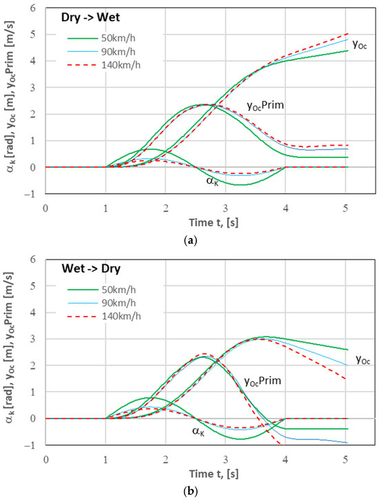
Figure 5.
Lane change (1LCM) simulation results. Change in the road surface condition: (a) the Dry→Wet type, i.e., from dry concrete (right lane) to wet concrete (left lane); (b) the Wet→Dry type, i.e., from wet concrete (right lane) to dry concrete (left lane).
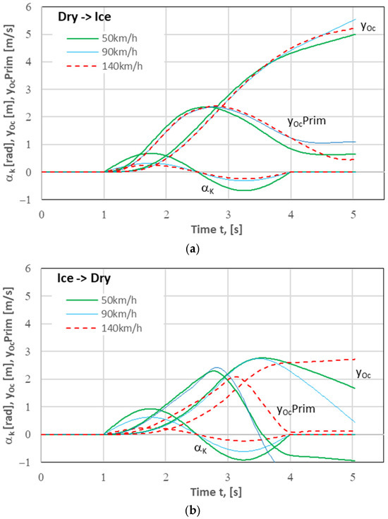
Figure 6.
Lane change (1LCM) simulation results. Change in the road surface condition: (a) the Dry→Ice type, i.e., from dry concrete (right lane) to ice (left lane); (b) the Ice→Dry type, i.e., from ice (right lane) to dry concrete (left lane).
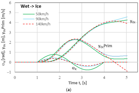
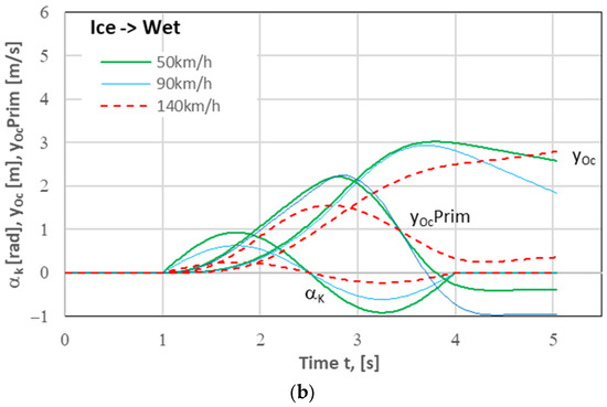
Figure 7.
Lane change (1LCM) simulation results. Change in the road surface condition: (a) the Wet→Ice type, i.e., from wet concrete (right lane) to ice (left lane); (b) the Ice→Wet type, i.e., from ice (right lane) to wet concrete (left lane).
The change in the road surface condition encountered when the vehicle changed the right lane to the left one significantly affected the time histories of the quantities represented in the graphs, i.e., lateral displacement and lateral velocity of vehicle’s centre of mass (yOc and dyOc/dt, respectively, the latter being denoted in the drawings as yOcPrim). Due to the use of the same form of the steering wheel input as it was in the case of the homogeneous road surface (based only on the right lane), the intended lateral displacement of the vehicle of 3.5 m could not be achieved. For the differences to be better illustrated, the trajectories of vehicle’s centre of mass plotted for 6 variants of the maneuver carried out on heterogeneous road surfaces have been compared in Figure 8 with the trajectories obtained for the homogeneous road surfaces.
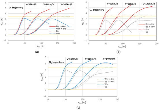
Figure 8.
Comparison of the trajectories of vehicle’s centre of mass observed for the 1LCM carried out on homogeneous and μ-split road surfaces: (a) Dry and Wet; (b) Dry and Ice; (c) Wet and Ice.
The differences between the lateral vehicle’s position relative to the line y = 3.5 m (i.e., the centreline of the left lane) reached (at the end of the maneuver) c.a. +2 m and −3 m, which indicates a great hazard, including even the risk of lane departure. Having noticed such a situation (excessive deviation from the desired trajectory), the driver should correct the input (after the necessary reaction time) in order to implement the lane change as assumed. Due to the typical reaction times of average drivers (1 s or even more [10,40,41,42,43]), it may be too late for any driver’s defensive action to be effective. However, we can imagine the use of an assistance system that could support or replace the driver in such situations. This will be the subject of the subsequent part of this article.
4.3. Verification of the Model of the Vehicle Trajectory to Be Adopted in the Assistance System
Figure 9 shows exemplary results for two trajectories, i.e., the one calculated for the theoretical model 3 (M3, but shifted by +0.22 s, to ensure conformity with the vehicle dynamics model) and the one obtained from the simulation of yOc(t) on the wet concrete road surface for the vehicle speed of V = 90 km/h. Here, the conformity can be seen very clearly.
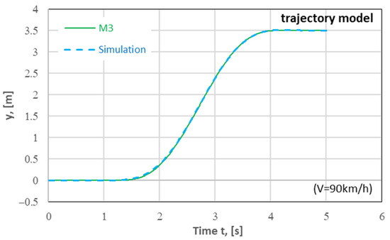
Figure 9.
Vehicle trajectories during a single lane change on a road section with a length of Lm = 75 m at the final lateral displacement of H = 3.5 m. Analytical model 3 (“M3”) by Zellner [34]. The result of a simulation yOc(t) (“Simulation”) for the wet concrete road surface at a speed of V = 90 km/h.
Attention should also be paid to the fact that for the maneuver carried out on an ice-covered road surface at high speeds (140 km/h in this case), the vehicle trajectory significantly differs from that observed in the other cases under analysis (see Figure 4c, Figure 6b and Figure 7b). The maneuver duration time (T) increases although the steering wheel input remains unchanged (Tw = 3 s). This will have an impact on the assistance system’s parameters adopted (see Section 4.4).
4.4. The 1LCM for the Vehicle with a Driver Assistance System
4.4.1. Examples of the Steering Wheel Angle Control Systems for the Lane Change Maneuver
The systems for the automatic controlling of the steering wheel angle during the lane change have been described in many publications, e.g., [6,7,8,9,11,12,13,17].
In the control strategy of the system described in [9], the lane change process is decomposed into time-related phases, which is in line with the driving practice of experienced drivers. In the first phase, the controlling is performed in a partly open system (“blindly”, “just fast”) by generating an appropriate turn of the steering wheel. The precision of this phase of the maneuver is ensured by the previously identified reference model of the vehicle dynamics. During this phase of the control process, corrective controlling also takes place. The course of changes in the steering wheel angle is corrected on the principle of regulation based on comparing the current should-be values of the variable that describes the lateral vehicle displacement according to the reference model with the current values of this variable, which are actually measured. In [6], the lane-changing maneuver is also analyzed as a multi-stage process carried out by controlling the steering angle of the steered wheels. This work highlights the benefits of using MPC (model predictive control) and SMC (Sliding Mode Control) algorithms and the use of neural networks to adjust the parameters of the control algorithm.
In publication [11], a model for controlling the steering system in a closed loop has been presented, where controllers of two types, i.e., proportional-integral (PI) and proportional-derivative (PD) ones, and a low-pass filter with the delay time at a level of 0.1 s, were used. In that work, a straight-line braking maneuver, with a possibility of changing it into a lane change when the driver notices a sudden change in the road surface grip, was successfully simulated.
In the work reported in [12], the object of control and regulation was a vehicle model with 9 degrees of freedom and a driver model was added to it. Preliminarily, the vehicle trajectory for the maneuver of keeping the lane at a constant speed was defined. The model of the controller was developed to control the steering wheel angle. The proposed structure of the controlling in the major loop of the controller model is a combination of the proportional gain control (P) with the adaptive control, using the fuzzy logic to control the yaw angle. In [7], a dual PID controller is considered to regulate the deviation of lateral displacement and yaw angle. The PID controller is also used in [8], where an assistant system called ACAS (adaptive collision avoidance strategy) was proposed, enriched with additional adaptive fuzzy-logic systems. The system is intended to ensure operation in conditions of variable speed and wheel adhesion to the road surface.
Other publications, e.g., [13,44,45] deal with V2V (vehicle-to-vehicle) and connected and automated vehicles (CAV) technology.
As it can be seen, various control methods, including very advanced and complex ones, are employed to address the issues of controlling the vehicle movement during the lane change maneuver. For this purpose, models of proportional-integral-differential (PID) controllers are used because of their relative simplicity, tried, proven, and documented operational reliability, and known methods of identification of their parameters [46,47,48]. In most cases, the predefined and planned vehicle trajectory is used as the reference.
4.4.2. The Steering Wheel Angle Control System Adopted for the Lane Change Maneuver
It was assumed that the car under test would be provided with a lane change assistance system as proposed below. Its operation has been illustrated in Figure 10. If it is ON, then the reference trajectory yp(x) is determined at the instant when a lane change is signalled. The trajectory parameters (H and Lm) depend on: (1) the lane width and the initial vehicle position on the first lane at the instant of signalling the intention to carry out the maneuver (it was assumed that these are determined by means of optical systems similar to those used for the parking and lane keeping sensors); (2) readings of the ambient temperature and rain presence sensors (based on these readings, the road surface condition is assessed, i.e., the question whether the road is dry, wet, or ice-covered is answered); and (3) the current vehicle speed V. Then, the reference trajectory (yp(x)) is transformed to the time domain (yp(t)) and the system starts the execution of the lane change maneuver. Two proportional-integral-differential (PID) controllers operating in parallel have been provided: for the lateral position yOc and the yaw angle ψC. The current values of yOc and ψC are calculated based on the readings of optical sensors (similar to those used in the parking and lane keeping sensors). The input signals are the deviations Δy and Δψ calculated for the lateral position yOc and the yaw angle ψC. The resultant value of the steering wheel angle is the weighted average of the components obtained from the two control systems operating in parallel, where the weighting factors are wy and wψ, as appropriate, according to Equation (5):
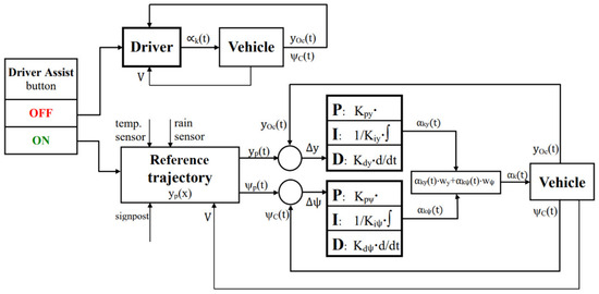
Figure 10.
Schematic diagram of the proposed lane change assistance system for the system being ON and OFF (see the description in the text).
The settings of the PID controllers were determined using a step input, where a controlled trajectory yP = 0 was applied for the instant t = 1 s, at the initial value of yP(0) = −H. The proportional control gains Kpy and Kpψ were selected to come close to the stability limit, i.e., to the appearance of non-decaying oscillation. Then, the equivalent delays of the object (vehicle) controlled and the equivalent time-constants of the vehicle under test were determined. Based on them, the controllers’ parameter values (Kpy, Kiy, Kdy and Kpψ, Kiψ, Kdψ) were determined by the Ziegler–Nichols method [46,47,48]. Apart from the controllers’ parameter values, the weighting factors for the summands αky(t) and αkψ(t) in Equation (5) had also to be determined. The raising of wy at the expense of wψ led to reductions of the phase shift of the trajectory (after the transformation to the time domain) relative to the reference one at the expense of the time histories of αk(t) becoming more irregular. When the opposite happened, the said phase shift increased but the courses of the steering wheel angle became smoother. Using the trial and error method, the controller parameters were slightly modified to values Kpy = 0.1 rad/m, Kiy = 38 s, Kdy = 6 s, Kpψ = 100 rad/rad, Kiψ = 80 s, and Kdψ = 12 s and the weighting factors equal to wy = wψ = 0.5 were used. In result of that, the upward trend in the phase shift was reduced and the αk(t) curves obtained were only slightly disturbed.
The real exemplification of the system proposed will require the use of a few protective elements to limit the values of yOc(t) and ψC(t) and, in consequence, of αk(t) as well as of their first derivatives in respect to time.
4.4.3. The 1LCM for the Vehicle with an Active Driver Assistance System, for the Homogeneous Road Surface
Figure 11 shows results for the single lane change maneuver, where an assistance system was used in comparison with the results with a sinusoidal input (Tw = 3 s), on a homogeneous road surface. The final lateral displacement and the vehicle speed were pre-set as H = 3.5 m and V = 90 km/h = 25 m/s, respectively. The maneuver began at the instant of t = 1 s. The time histories of the input, i.e., steering wheel angle αk(t), and of the response, i.e., lateral displacement of vehicle’s centre of mass yOc(t) and yaw angle ψC(t), have been shown. The curves represent the reference course (Reference), the result obtained in the maneuver controlled by the open system with a sinusoidal input (Sine), and the result of operation of the assistance system described herein (Assist. S.). After performing the maneuver, the car should move parallel to the lane centre line and a sketch of the car should not leave the lane. Knowing vehicle width gives limits for the vehicle’s c.g. lateral displacement.
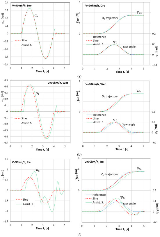
Figure 11.
Results of the simulation of the vehicle motion (steering wheel angle αk; lateral displacement of vehicle’s centre of mass yOc and yaw angle ψC) during the 1LCM where an assistance system was used. Vehicle speed: V = 90 km/h. Road surface: (a) Dry concrete; (b) Wet concrete; (c) Ice-covered.
These results indicate that the assistance system correctly executes the vehicle motion along the preset trajectory treated as a reference. However, the curve yOc(t) is shifted along the time axis with decreasing tyre–road adhesion coefficient (from dry concrete through wet concrete to ice). This indicates that on the road surfaces with less grip, the vehicle responds with some delay and a bit slower, which results from an increase in the tyre sideslip angles. This is reflected in the graphs that show the time histories of the yaw angle ψC(t) and of the controlled quantity, i.e., the steering wheel angle αk(t). Such a phenomenon could also be observed when comparing the curves in Figure 4 (Section 4.1), which represented the results obtained in the maneuver controlled by the open system with a sinusoidal input applied to the steering wheel, carried out on roads with less and less grip.
Moreover, a small overshoot in the yOc(t) curve can be seen for the ice-covered road surface (Figure 11c). Nevertheless, the effect of operation of the assistance system may be considered satisfactory. The system can substitute for the driver in executing the maneuver planned.
4.4.4. The 1LCM for the Vehicle with an Active Driver Assistance System, for the Heterogeneous Road Surface
For the car provided with a lane change assistance system described herein, simulations were carried out that corresponded to those presented in Section 4.2 (Figure 5, Figure 6, Figure 7 and Figure 8), i.e., for the μ split road surfaces in combinations as specified in Table 1, and the effect of the operation of such a system was assessed. For illustration, the most spectacular cases were selected, including those that highlight the possible imperfections of the control type employed (the Dry→Ice and Ice→Dry cases).
Figure 12 shows the results obtained for the maneuver with dry concrete surface of the right lane and ice-covered surface of the left lane (the Dry→Ice case) and for the case with ice-covered right lane and dry concrete left lane (the Ice→Dry case). All the other test parameters were as before, i.e., maneuver duration time Tw = 3 s, anticipated final lateral vehicle displacement H = 3.5 m, the maneuver began at the instant of t = 1 s, and the vehicle speed was V = 90 km/h = 25 m/s. The curves in the graphs represent steering wheel angle αk(t), lateral displacement of vehicle’s centre of mass yOc(t), and yaw angle ψC(t) and show the reference course (Reference), the result obtained in the maneuver controlled by the open system with a sinusoidal input and carried out on a homogeneous dry concrete road surface (Sine Dry), and the result of operation of the assistance system under consideration on the heterogeneous road surface (Assist. S.).
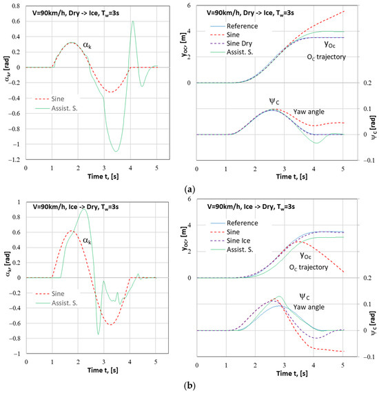
Figure 12.
Results of the simulation of the vehicle motion (steering wheel angle αk; lateral displacement of vehicle’s centre of mass yOc and yaw angle ψC) during the 1LCM where an assistance system was used for a change in the road surface condition: (a) the Dry→Ice type, i.e., from dry concrete (right lane) to ice (left lane); (b) the Ice→Dry type, i.e., from ice (right lane) to dry concrete (left lane). Vehicle speed: V = 90 km/h.
It can be seen that the vehicle response is significantly delayed when the vehicle is on the ice-covered surface at the start of the maneuver (similar vehicle behaviour can be observed when the vehicle is moving without the assistance system, especially at high speeds—see Figure 4c, Figure 6b and Figure 7b).
The results presented indicate that the assistance system definitely improves vehicles’ behaviour compared to that observed during the maneuver carried out on a μ-split road surface and controlled by the open system with a sinusoidal input applied to the steering wheel. The vehicle remains within the target lane, although the actual final lateral displacement values differ from that having been preset (the difference is about 0.4 m, both positive and negative), and the vehicle moves parallel to the road direction (Ox).
The error of the lateral vehicle’s position can be reduced by lowering the proportional control gain Kpψ (for the yaw angle). However, this would raise the variability of the steering wheel angle and oscillations of the yaw angle ψC(t). The oscillations, in turn, can be reduced by extending the lane change time. For vehicle speeds of V = 90 km/h and higher, the lane change time (the Tw period) was extended to a value of 4 s (without changing the values of Kpy and Kpψ). Such an action improves the conditions of operation of the assistance system and lowers the intensity of turning the steering wheel and the values of lateral acceleration and yaw velocity. The effects of these actions have been presented in Figure 13, which corresponds to Figure 12. Thus, the functioning of the assistance system is markedly improved, and the error of the lateral vehicle’s position is decreased.
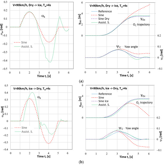
Figure 13.
Results of the simulation of the vehicle motion (steering wheel angle αk; lateral displacement of vehicle’s centre of mass yOc and yaw angle ψC) during the 1LCM where an assistance system was used for a change in the road surface condition: (a) the Dry→Ice type, i.e., from dry concrete (right lane) to ice (left lane); (b) the Ice→Dry type, i.e., from ice (right lane) to dry concrete (left lane). Vehicle speed: V = 90 km/h. Maneuver duration time Tw = 4 s.
It was decided to check whether the assistant system proposed would work correctly for the most difficult case of those considered (the lane change at a speed of V = 140 km on the “μ-split” road surface, Dry→Ice and Ice→Dry lane change combinations). Figure 14 shows the results obtained for a maneuver carried out at such a speed, where an assistance system was used, for a maneuver duration time of Tw = 4 s. As in the previous cases, the curves represent the input applied, i.e., the steering wheel angle αk(t) in the sinusoidal form controlled by the open system (Sine) and in the form controlled by the assistant system (Assist. S.), and the responses, i.e., lateral displacement yOc(t) and yaw angle. The curves include those adopted as the reference (Reference), those obtained as a result in the maneuver controlled by the open system with a sinusoidal input and carried out on a homogeneous road surface (Sine Dry, i.e., on dry concrete, see Figure 14a, and Sine Ice, i.e., ice, see Figure 14b) and carried out on a heterogeneous road surface (Sine) and in the maneuver controlled by the assistance system under consideration (Assist. S.). The maneuver began at the instant of t = 1 s.
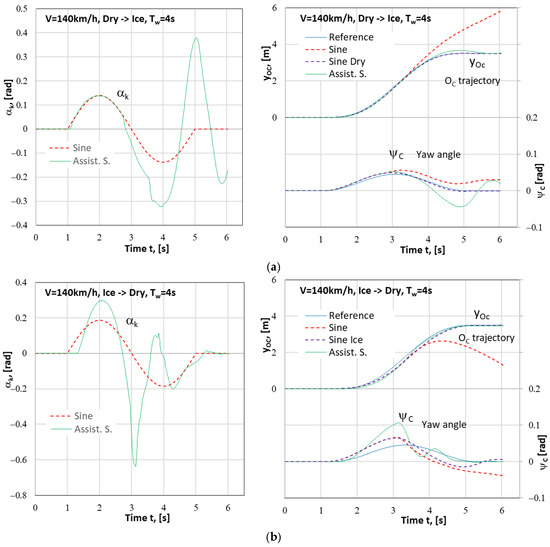
Figure 14.
Results of the simulation of the vehicle motion (steering wheel angle αk; lateral displacement of vehicle’s centre of mass yOc and yaw angle ψC) during the 1LCM where an assistance system was used for a change in the road surface condition: (a) the Dry→Ice type, i.e., from dry concrete (right lane) to ice (left lane); (b) the Ice→Dry type, i.e., from ice (right lane) to dry concrete (left lane). Vehicle speed V = 140 km/h. Maneuver duration time Tw = 4 s.
As in the case with the vehicle speed of V = 90 km/h, the extending of the lane change time from 3 s to 4 s and the reducing of the proportional control gain Kpψ, without changing Kpy, led to very satisfactory results, i.e., the vehicle trajectories were implemented correctly. A disadvantage of the second of the mentioned changes to the PID controller of the assistance system is an increase in the intensity of changes in the yaw angle ψC and in the steering wheel angle αk (which can be seen in Figure 14). This slightly reduces the desirable effects of extending the lane change time Tw. Such functioning of the assistance system may cause some anxiety for the driver. Nevertheless, the system fulfills its task.
5. Conclusions
A change in the condition of the road surface on which the vehicle is moving during the lane change maneuver (from the right lane to the left one) significantly affects the time histories of the lateral displacement of vehicle’s centre of mass and of the yaw angle as well as of their time derivatives, i.e., velocities. If the input applied to the steering wheel is in the same form as it would be in the case of the homogeneous road surface (i.e., where the left lane surface is identical to that of the right one), then it will be impossible to achieve the intended lateral displacement and the yaw angle of the vehicle. Having noticed such a situation, the driver should correct the input (after the necessary reaction time) in order to implement the lane change as assumed. Unfortunately, in many cases of the vehicle motion under analysis, it is too late (due to the driver reaction time of 1 s or more) to eliminate the threat that has emerged in the form of large differences in vehicle’s position and yaw angle from those expected (intended). This leads to a very high risk of an accident resulting from vehicle’s departure from the occupied lane or even the road.
The proposed assistance system based on a PID controller correctly implements the motion along the assumed trajectory, treated as a reference (a pre-set one) on a homogeneous surface. It has been observed, however, that the course of the vehicle trajectory (transformed to the time domain) is shifted along the time axis with decreasing tyre-road adhesion coefficient (from dry concrete through wet concrete to ice). This indicates that on the road surfaces with less grip, the vehicle responds with some delay and a bit slower, which results from an increase in the tyre sideslip angles. This is reflected in the graphs showing the yaw angle and the time history of the controlled quantity, i.e., the steering wheel angle. Moreover, a slight inaccuracy in the course of vehicle’s lateral position can be seen for the ice-covered road surface. Nevertheless, the effect of operation of the assistance system may be considered satisfactory. The system can substitute for the driver in executing the maneuver planned. The results presented indicate that the assistance system definitely improves vehicle’s behaviour in comparison with that observed during the maneuver carried out on a heterogeneous road surface and controlled by the open system with a sinusoidal input applied to the steering wheel. The vehicle remains within the second lane. In this work, the components of the control system have been indicated that have an impact on the error of lateral vehicle’s displacement. The said error can be reduced, but the reduction may be accompanied by greater variability of the course of the steering wheel angle and oscillations of vehicle’s yaw angle. Such functioning of the assistance system may cause some anxiety for the driver. This possible negative aspect should be tested when checking prototype devices or during driving simulator tests.
It is worth emphasizing that the assistance system proposed in this article fulfils its tasks even for the motion with a very high speed (140 km/h) on a homogeneous road surface (even if ice-covered) as well as for the case where the tyre–road adhesion is changing during a lane change maneuver. Thanks to this, it is possible to avoid the risk of an accident, which (as shown) is real when the vehicle is driven in a routine way. The presented results show that traditional, well-known (and tested in many real-world applications) PID controllers are enough effective compared with newer methods (e.g., MPS—Model Predictive Control or SMC—Sliding Mode Control).
The authors claim that for reproducibility of the presented work, the most important are the described method, simulation model, block diagram of the proposed lane change assistant system (Figure 10), and description of the way how to determine the controller parameters (see Section 4.4.2). This gives a big chance to reproduce the described control system for other vehicles, for another author’s research.
The proposed system has (of course) some limitations. These are the minimum and maximum values of the steering wheel angle, steering wheel angular velocity, and torque on the steering wheel. In the presented research, the mentioned variables did not reach the limits, but it is important to remember such limitations. In the paper, the authors wanted to recognize the main problems dealing with the application of the presented idea. The simulation method is a very good tool for it. In further works, it is planned to consider uncertainty problems (due to a number of passengers or amount of load in the vehicle, etc.), e.g., adaptive controllers.
Author Contributions
Conceptualization, Z.L. and M.G.; methodology, Z.L. and M.G.; software, Z.L.; validation, M.G. and Z.L.; formal analysis, M.G. and Z.L.; investigation, M.G. and Z.L.; writing—original draft preparation, Z.L. and M.G.; writing—review and editing, M.G. and Z.L. All authors have read and agreed to the published version of the manuscript.
Funding
This paper was co-financed under the research grant of the Warsaw University of Technology supporting the scientific activity in the discipline of Civil Engineering, Geodesy and Transport.
Institutional Review Board Statement
Not applicable.
Informed Consent Statement
Not applicable.
Data Availability Statement
The original contributions presented in this study are included in the article. Further inquiries can be directed to the corresponding authors.
Conflicts of Interest
The authors declare no conflicts of interest.
Abbreviations
| 1LCM | Single Lane change Maneuver |
| ABS | Anti-lock Brake Systems |
| ACAS | Adaptive Collision Avoidance Strategy |
| ACC | Adaptive Cruise Control |
| ASR | Acceleration Slip Regulation |
| AV | Autonomous Vehicle |
| BAS | Brake Assist Systems |
| CAV | Connected and Automated Vehicles |
| EBD | Electronic Brake Distribution |
| ESP | Electronic Stability Program |
| HSRI-UMTRI | University of Michigan Highway Safety Research Institute (USA) |
| IPG | The name of company |
| LDW | Lane Departure Warning system |
| M3 | Trajectory model by Zellner [34] |
| MPC | Model Predictive Control |
| PD | Proportional-Derivative |
| PI | Proportional-Integral |
| PID | Proportional-Integral-Derivative |
| SAE | Society of Automotive Engineers |
| SMC | Sliding Mode Control |
| TCS | Traction Control Systems |
| V2V | Vehicle-to-Vehicle |
| Symbols | |
| αk | Steering wheel angle |
| αky, αkψ | Output signals from PID controllers in the assistant control system |
| Δy, Δψ | Input signals to the assistant control system—lateral position and yaw angle deviations |
| φC | Car body pitch angle (rotation around the OCηC axis) |
| μ0 | the maximum value of the tyre–road adhesion coefficient—maximum value of unit tangential force in tyre–road contact (for v being close to zero) |
| μx | unit longitudinal force in tyre–road contact |
| μy | unit lateral force in tyre–road contact |
| ψ | Car body yaw angle (in general) |
| ψC | Car body yaw angle (rotation around the OCζC axis) |
| ϑC | Car body roll angle (rotation around the OCξC axis) |
| Assist. S. | Assistant control system |
| c.g. | Car body centre of gravity—point OC |
| cx | kinematic circumferential stiffness of the tyre |
| cy | cornering stiffness of the tyre |
| Dry | Dry concrete road surface |
| H | Planned maximum lateral vehicle displacement during the performing of the single lane change maneuver |
| Ice | Ice-covered concrete road surface |
| kp | Lateral stiffness of the tyre |
| kv | Coefficient of influence of slip velocity on the tyre–road adhesion coefficient |
| Kpy, Kiy, Kdy | Lateral position deviation PID controller parameter values |
| Kpψ, Kiψ, Kdψ | Yaw angle deviation PID controller parameter values |
| L | Left lane of the road |
| Lm | Longitudinal vehicle displacement during the single lane change maneuver road |
| Mz | Aligning moment in tyre–road contact |
| O1, O2, O3, O4 | Points of concentration of car’s “unsprung masses” |
| OC | Car body centre of mass |
| Oxyz | Inertial system attached to the road (horizontal axes Ox and Oy and vertical axis Oz |
| OCxCyCzC | Non-inertial system with axes parallel to the Ox, Oy, and Oz axes (respectively), with its origin situated at the car body centre of mass Oc |
| OCξCηCζC, O1ξ1η1ζ1, O2ξ2η2ζ2, O3ξ3η3ζ3, O4ξ4η4ζ4 | Non-inertial coordinate systems fixed to model’s rigid bodies, i.e., body solid and four road wheels |
| R | Right lane of the road |
| Sine | Sinusoidal excitation |
| t | Time |
| T | Maneuver duration time |
| Tw | Steering wheel input duration time |
| v [m/s], V [km/h] | Vehicle velocity (exactly: velocity of the centre of mass OC) |
| wy, wψ | Weighting factors in the assistant control system |
| Wet | Wet concrete road surface |
| x | Longitudinal vehicle displacement (along the Ox axis) |
| y | Lateral vehicle displacement (along the Oy axis) |
| xOC, yOC, zOC | Position of the centre of mass OC in the inertial reference system Oxyz |
| yOcPrim ≡ dyOc/dt | Lateral velocity (in Oy direction) of vehicle’s centre of mass OC |
| yp(x/t) | Reference trajectory in position/time domain |
References
- SAE J3016; Surface Vehicle Recommended Practice. Taxonomy and Definitions for Terms Related to Driving Automation Systems for On-Road Motor Vehicles. SAE International: Warrendale, PA, USA, 2021.
- Ali, Y.; Haque, M.M.; Zheng, Z.; Washington, S.; Yildirimoglu, M. A hazard-based duration model to quantify the impact of connected driving environment on safety during mandatory lane-changing. Transp. Res. Part C Emerg. Technol. 2019, 106, 113–131. [Google Scholar] [CrossRef]
- Xu, G.; Liu, L.; Ou, Y.; Song, Z. Dynamic modeling of driver control strategy of lane-change behavior and trajectory planning for collision protection. IEEE Trans. Intell. Transp. Syst. 2012, 13, 1138–1155. [Google Scholar] [CrossRef]
- Van Winsum, W.; De Waard, D.; Brookhuis, K.A. Lane change manoeuvres and safety margins. Transp. Res. Part F Traffic Psychol. Behav. 1999, 2, 139–149. [Google Scholar] [CrossRef]
- Jula, H.; Kosmatopoulos, E.B.; Ioannou, P. Collision Avoidance Analysis for Lane Changing and Merging; Research Report UCB-ITS-PRR-99-13; University of California: Berkeley, CA, USA, 1999; Available online: https://escholarship.org/uc/item/3zh107m3 (accessed on 29 October 2024).
- Deng, L.; Ni, W.; Zhou, T.; Yu, Y.; Zhai, L. Analysis of Vehicle Assisted Lane Change System and Autonomous Lane Change Model. In Proceedings of the 2022 Fourth International Conference on Emerging Research in Electronics, Computer Science and Technology (ICERECT), Mandya, India, 26–27 December 2022; pp. 1–6. [Google Scholar] [CrossRef]
- Hong, J.; Choi, J.; Woo, S.; Lee, J.; Lee, S.G.; Kim, J.; Cha, K. Automatic Lane Change System with Double Loop PID Algorithm. In Proceedings of the 22nd International Conference on Control, Automation and Systems (ICCAS), Jeju, Republic of Korea, 27 November–1 December 2022; pp. 1977–1980. [Google Scholar] [CrossRef]
- Wang, J.; Huang, G.; Yuan, X.; Liu, Z.; Wu, X. An adaptive collision avoidance strategy for autonomous vehicle under various road friction and speed. ISA Trans. 2023, 143, 131–143. [Google Scholar] [CrossRef] [PubMed]
- Gidlewski, M.; Jemioł, L.; Żardecki, D. Simulation investigation of the dynamics of the process of sudden obstacle avoiding by a motor vehicle. Arch. Automot. Eng. 2016, 73, 31–46. [Google Scholar] [CrossRef]
- Jurecki, R.S. Badania i Modelowanie Reakcji Kierowców w Sytuacjach Zagrożenia Wypadkowego [Research and Modeling of Drivers’ Reactions in Accident Risk Situations]; Monograph; Publishing Hause of Kielce University of Technology: Kielce, Poland, 2016; Volume M84. (In Polish) [Google Scholar]
- Şahin, H. Collision avoidance via adaptive trajectory control in case of a sudden decrease in the maximum road friction coefficient. Promet—Traffic Transp. 2017, 29, 469–478. [Google Scholar] [CrossRef]
- Em, P.P.; Hudha, K.; Jamaluddin, H. Automatic steering control for lanekeeping manoeuvre: Outer-loop and inner-loop control design. Int. J. Adv. Mechatron. Syst. 2010, 2, 350–368. [Google Scholar] [CrossRef]
- An, H.; Jung, J. Design of a cooperative lane change protocol for a connected and automated vehicle based on an estimation of the communication delay. Sensors 2018, 18, 3499. [Google Scholar] [CrossRef]
- Obłój, M. Wpływ stanu nawierzchni dróg oraz poboczy na bezpieczeństwo ruchu drogowego [The influence of road surface and shoulders condition on road safety]. Drogownictwo 2011, 10, 307–312. (In Polish) [Google Scholar]
- Hayashi, R.; Isogai, J.; Raksincharoensak, P.; Masao Nagai, M. Autonomous collision avoidance system by combined control of steering and braking using geometrically optimised vehicular trajectory. Veh. Syst. Dyn. 2012, 50 (Suppl. S1), 151–168. [Google Scholar] [CrossRef]
- Zainal, Z.; Rahiman, W.; Baharom, M.N. Yaw rate and sideslip control using PID controller for double lane changing. J. Telecommun. Electron. Comput. Eng. 2017, 9, 99–103. [Google Scholar]
- Park, M.; Yim, S. Comparative Study on Coordinated Control of Path Tracking and Vehicle Stability for Autonomous Vehicles on Low-Friction Roads. Actuators 2023, 12, 398. [Google Scholar] [CrossRef]
- Lozia, Z. Modele Symulacyjne Ruchu i Dynamiki Dwóch Pojazdów Uprzywilejowanych [Vehicle Dynamics Simulation Models of Two Emergency Vehicles]; Technical Transactions “Mechanics”; 109/8/3-M; Cracow University of Technology: Cracow, Poland, 2012; pp. 19–34. ISSN 0011-4561. (In Polish) [Google Scholar]
- Lozia, Z. Examples of authorial models for the simulation of motor vehicle motion and dynamics. Zeszyty Naukowe Instytutu Pojazdów 2015, 104, 9–27, ISSN 1642-347X. [Google Scholar]
- Lozia, Z. Simulation testing of two ways of disturbing the motion of a motor vehicle entering a skid pad as used for tests at Driver Improvement Centres. Arch. Automot. Eng. 2016, 72, 111–125. [Google Scholar] [CrossRef]
- Kamiński, E.; Pokorski, J. Teoria Samochodu. Dynamika Zawieszeń i Układów Napędowych Pojazdów Samochodowych [The Car Theory. Dynamics of Suspensions and Drive Systems of Motor Vehicles]; WKŁ: Sulejówek, Poland, 1983. (In Polish) [Google Scholar]
- Lozia, Z. Symulatory Jazdy Samochodem [Driving Simulators]; WKŁ: Sulejówek, Poland, 2008. (In Polish) [Google Scholar]
- Lozia, Z. Analiza Ruchu Samochodu Dwuosiowego na Tle Modelowania Jego Dynamiki [The Analysis of the Movement of a Two-axle Car on the Background of Modelling Its Dynamics]; Scientific Papers of Warsaw University of Technology—Transport, Sheet 41, Monograph; Warsaw University of Technology: Warszawa, Poland, 1998; ISSN 1230-9265. (In Polish) [Google Scholar]
- Maryniak, J. Dynamiczna Teoria Obiektów Ruchomych [The Dynamic Theory of Moving Objects]; Scientific Papers of Warsaw University of Technology—Mechanics, Monograph; Warsaw University of Technology: Warszawa, Poland, 1975; ISSN 0137-2335. (In Polish) [Google Scholar]
- Dugoff, H.; Fancher, P.S.; Segel, L. An Analysis of Tire Traction Properties and Their Influence on Vehicle Dynamic Performance; SAE Technical Paper 700377; SAE International: Warrendale, PA, USA, 1970. [Google Scholar] [CrossRef]
- Fancher, P.S., Jr.; Bareket, Z. Including roadway and tread factors in semi-empirical model of truck tyres. Veh. Syst. Dyn. 1993, 21, 92–107. [Google Scholar] [CrossRef]
- Schieschke, R. The importance of tire dynamics in vehicle simulation. In Proceedings of the Tire Society 9th Annual Meeting and Conference on Tire Science and Technology, Akron, OH, USA, 20–21 March 1990. [Google Scholar]
- ISO 7401:2011; Road Vehicles—Lateral Transient Response Test Methods—Open-Loop Test Methods. International Organization for Standardization: Geneva, Switzerland, 2011. Available online: https://www.iso.org/standard/54144.html (accessed on 29 October 2024).
- MR807; Lane Change Manoeuvre Test Procedures. Vehicle Standards Fact Sheet: Adelaide, Australia, 2020. Available online: https://www.sa.gov.au/topics/driving-and-transport/vehicles/vehicle-standards-and-modifications/lane-change-manoeuvre-test-procedures (accessed on 1 October 2024).
- ISO 3888-2:2011; Passenger Cars—Test Track for a Severe Lane-Change Manoeuvre—Part 2: Obstacle Avoidance. International Organization for Standardization: Geneva, Switzerland, 2011. Available online: https://www.iso.org/standard/57253.html (accessed on 29 October 2024).
- Pieniążek, W.; Więckowski, D. Badania Kierowalności i Stateczności Pojazdów Samochodowych [Handling and Stability Tests of Motor Vehicles]; PWN: Warszawa, Poland, 2020. (In Polish) [Google Scholar]
- Bascunana, J.L. Analysis of Lane Change Crash Avoidance; SAE Technical Paper 951895; SAE International: Warrendale, PA, USA, 1995. [Google Scholar] [CrossRef]
- Papić, Z.M.; Zovak, G.; Bogdanović, V.; Saulić, N.J. Empirical approach for determining lane change distance at obstacle avoidance manoeuvre. Promet—Traffic Transp. 2016, 28, 267–275. [Google Scholar] [CrossRef][Green Version]
- Zellner, J.W.; Weir, D.H. Development of Handling Test Procedures for Motorcycles; SAE Technical Paper 780313; SAE International: Warrendale, PA, USA, 1978. [Google Scholar] [CrossRef]
- Nelson, W. Continuous-curvature path for autonomous vehicles. In Proceedings of the 1989 International Conference on Robotics and Automation, Scottsdale, AZ, USA, 14–19 May 1989; Volume 3, pp. 1260–1264. [Google Scholar] [CrossRef]
- Samiee, S.; Azadi, S.; Kazemi, R.; Eichberger, A. Towards a decision-making algorithm for automatic lane change manoeuvre considering traffic dynamics. Promet—Traffic Transp. 2016, 28, 91–103. [Google Scholar] [CrossRef]
- Mikulec, R.; Semela, M.; Bradáč, A.; Tokař, S.; Bilík, M.; Křižák, M.; Belák, M.; Kledus, R.; Haring, A.; Rábek, V. Obsolete or viable? Revision of lane-change manoeuvre duration empirical calculation. Energies 2021, 14, 8439. [Google Scholar] [CrossRef]
- Official Gazette 2016.0.124. Regulation of the Minister of Transport and Maritime Economy of March 2, 1999 on the Technical Conditions to Be Met by Public Roads and Their Location. Section III, Chapter 2, § 15. Available online: https://isap.sejm.gov.pl/isap.nsf/DocDetails.xsp?id=wdu19990430430 (accessed on 29 October 2024). (In Polish)
- Samani, A.R.; Mishra, S.; Dey, K. Assessing the effect of long-automated driving operation, repeated take-over requests, and driver’s characteristics on commercial motor vehicle drivers’ driving behavior and reaction time in highly automated vehicles. Transp. Res. Part F Traffic Psychol. Behav. 2022, 84, 239–261. [Google Scholar] [CrossRef]
- Stańczyk, T.L. Działania Kierowcy w Sytuacjach Krytycznych. Badania Eksperymentalne i Modelowe [Driver Actions in Critical Situations. Experimental and Model Research]; Monograph; Publishing Hause of Kielce University of Technology: Kielce, Poland, 2013; Volume M43. (In Polish) [Google Scholar]
- Jurecki, R.S.; Stańczyk, T.L.; Jaśkiewicz, M.J. Driver’s reaction time in a simulated, complex road incident. Transport 2017, 32, 44–54. [Google Scholar] [CrossRef]
- Wierciński, J.; Reza, A. (Eds.) Road accidents. In Forensic Expert Handbook; Publishing House of the Institute of Forensic Expertise of Prof. Dr. Jan Sehn in Cracow: Cracow, Poland, 2006. [Google Scholar]
- Arczyński, S. Mechanika Ruchu Samochodu [Car Motion Mechanics]; WNT: Warszawa, Poland, 1993. (In Polish) [Google Scholar]
- Wang, C.; Du, Y. Lane-changing strategy based on a novel sliding mode control Approach for Connected Automated Vehicles. Appl. Sci. 2022, 12, 11000. [Google Scholar] [CrossRef]
- Zhang, S.; Deng, G.; Yang, E.; Ou, J. Optimal Vehicle Lane Change Trajectory Planning in Multi-vehicle Traffic Environments. Appl. Sci. 2022, 12, 9662. [Google Scholar] [CrossRef]
- Kowal, J. Podstawy Automatyki [Basics of Automation], Vol I and II. 3rd edition revised and enlarged; AGH University Press: Cracow, Poland, 2006. (In Polish) [Google Scholar]
- Skup, Z. Podstawy Automatyki i Sterowania [Basics of Automation and Control]; Warsaw University of Technology—Faculty of Automotive and Construction Machinery Engineering: Warsaw, Poland, 2012. (In Polish) [Google Scholar]
- Frank, S.A. Control Theory Tutorial: Basic Concepts Illustrated by Software Examples; Springer International Publishing AG: Cham, Switzerland, 2018. [Google Scholar] [CrossRef]
Disclaimer/Publisher’s Note: The statements, opinions and data contained in all publications are solely those of the individual author(s) and contributor(s) and not of MDPI and/or the editor(s). MDPI and/or the editor(s) disclaim responsibility for any injury to people or property resulting from any ideas, methods, instructions or products referred to in the content. |
© 2024 by the authors. Licensee MDPI, Basel, Switzerland. This article is an open access article distributed under the terms and conditions of the Creative Commons Attribution (CC BY) license (https://creativecommons.org/licenses/by/4.0/).