
Development of a Deployable Reflector Antenna for the Synthetic Aperture Radar Satellite, Part 2: Manufacturing and Qualification of the Main Reflector Using a Honeycomb Sandwich Composite Structure

Abstract
1. Introduction
2. Manufacturing the Composite Main Reflector
2.1. Deployable Reflector Antenna Requirements Derivation
2.2. Initial Design of the Composite Main Reflector
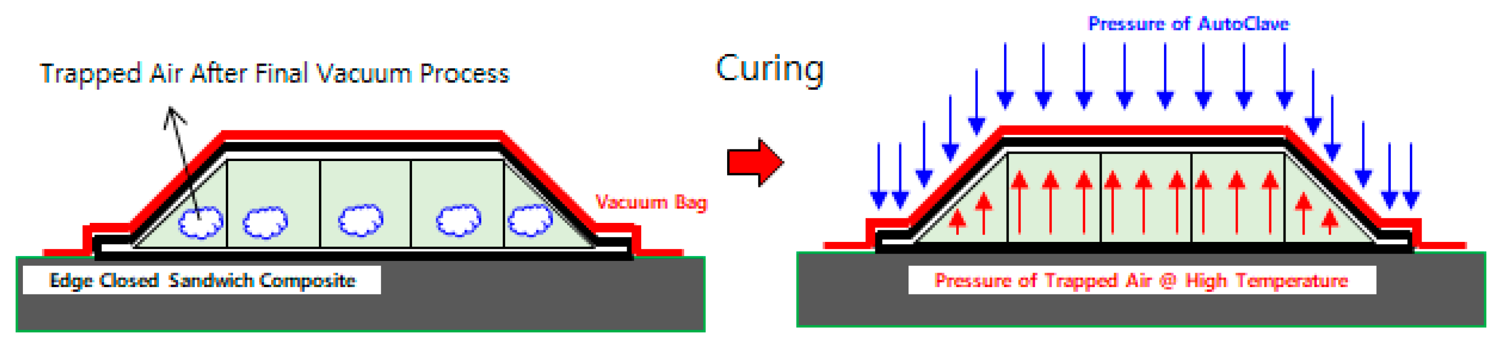
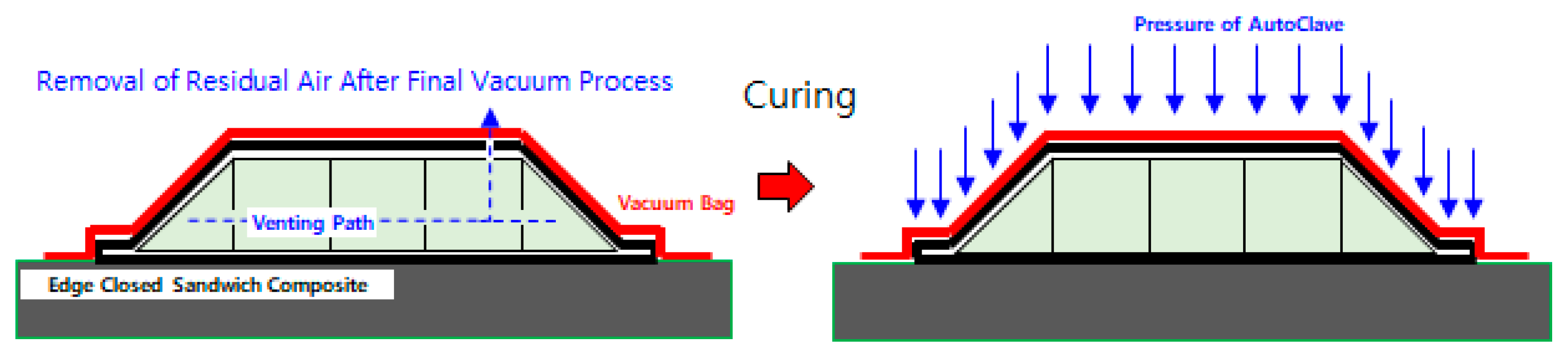
2.3. Verification of Manufacturing Process Variables
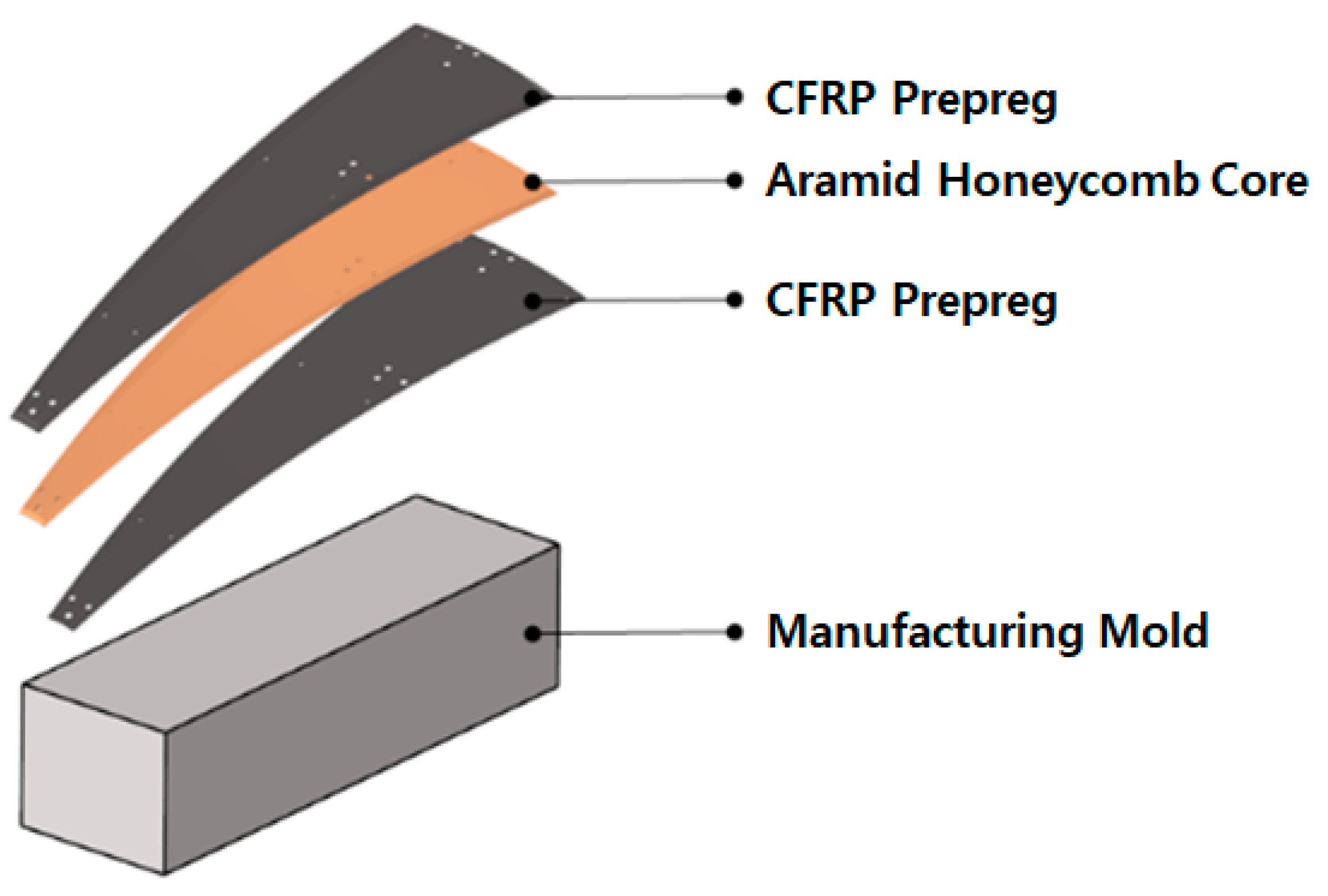
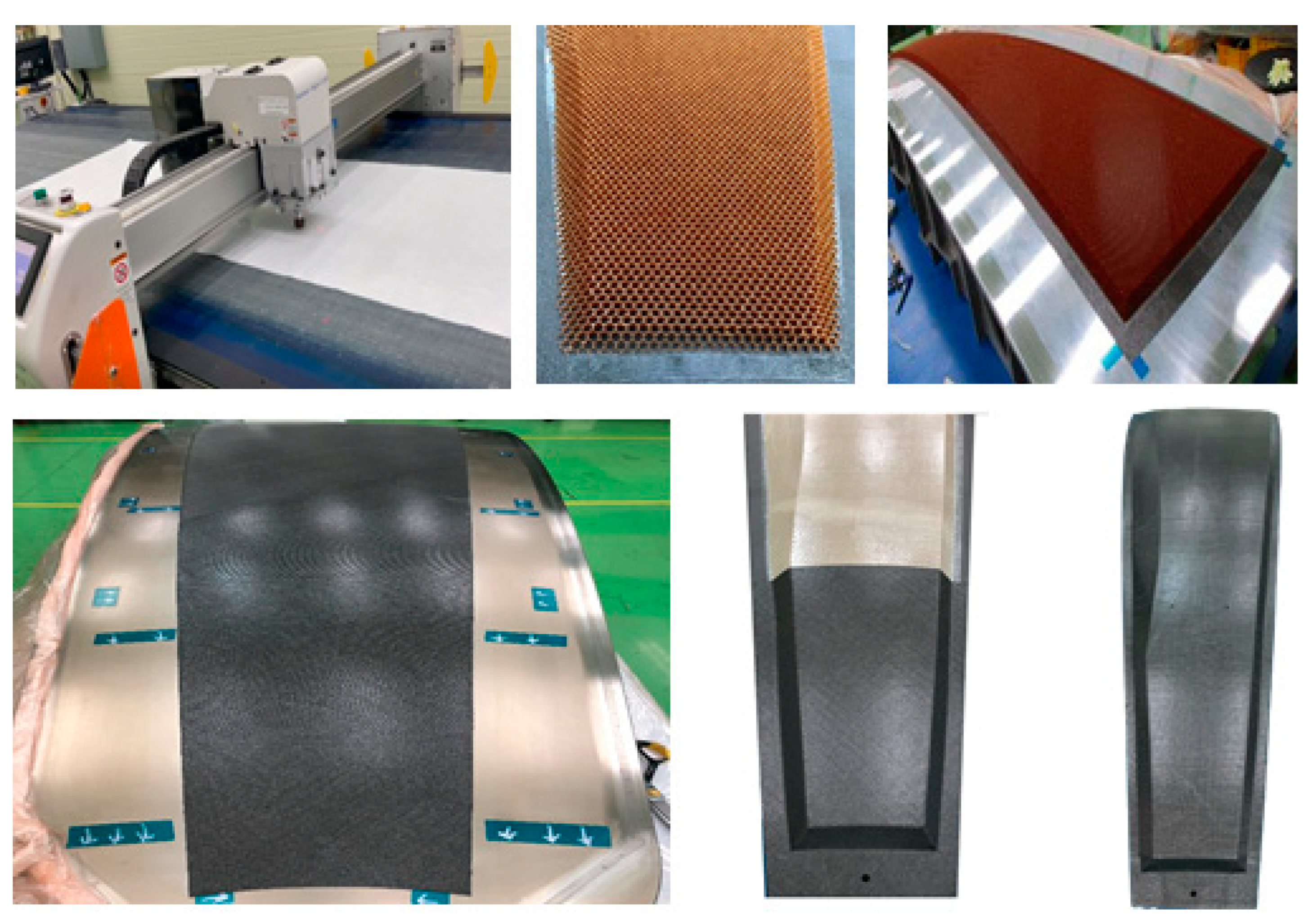
2.4. Manufacturing the Composite Reflector
3. Verification of the Composite Main Reflector
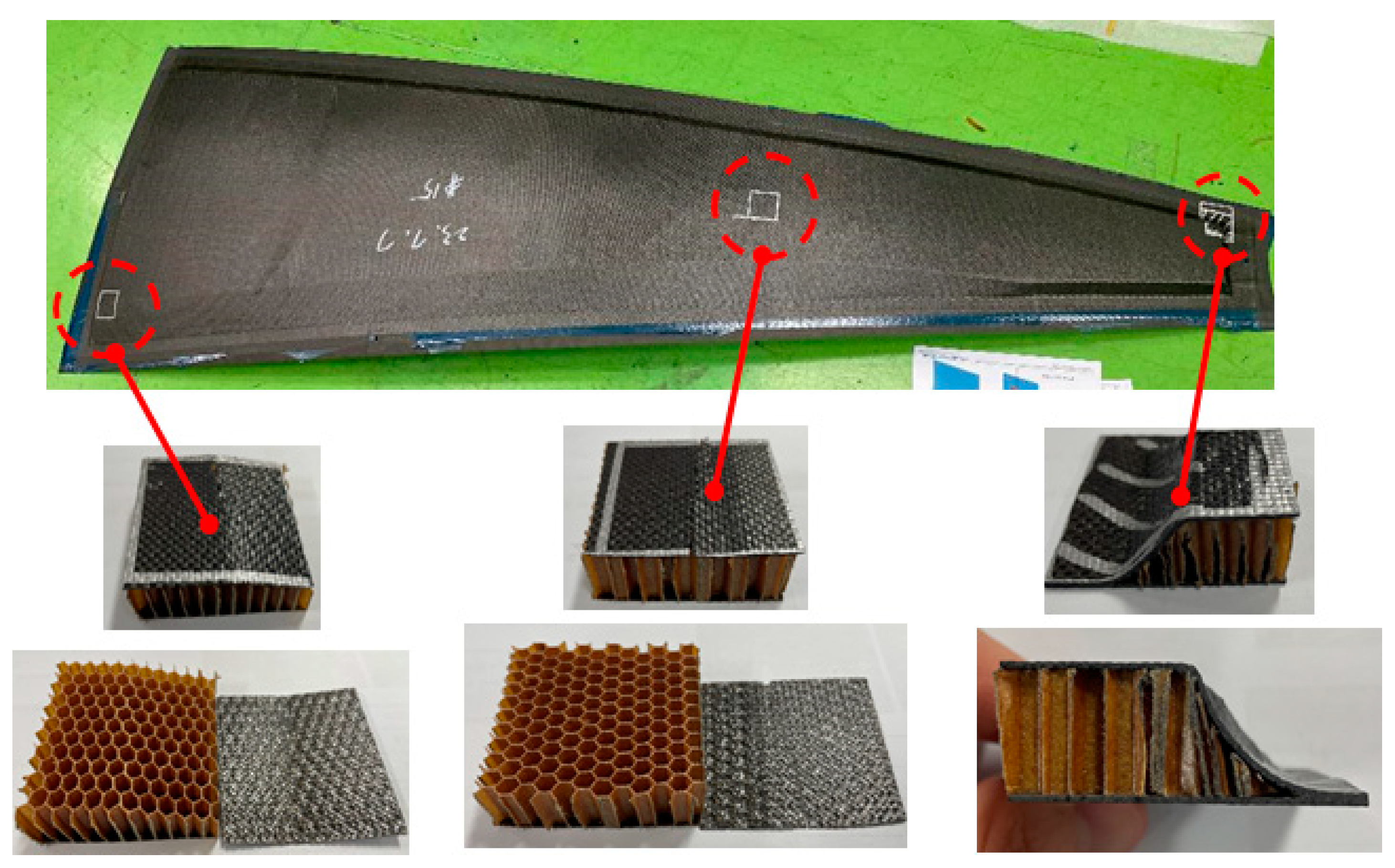
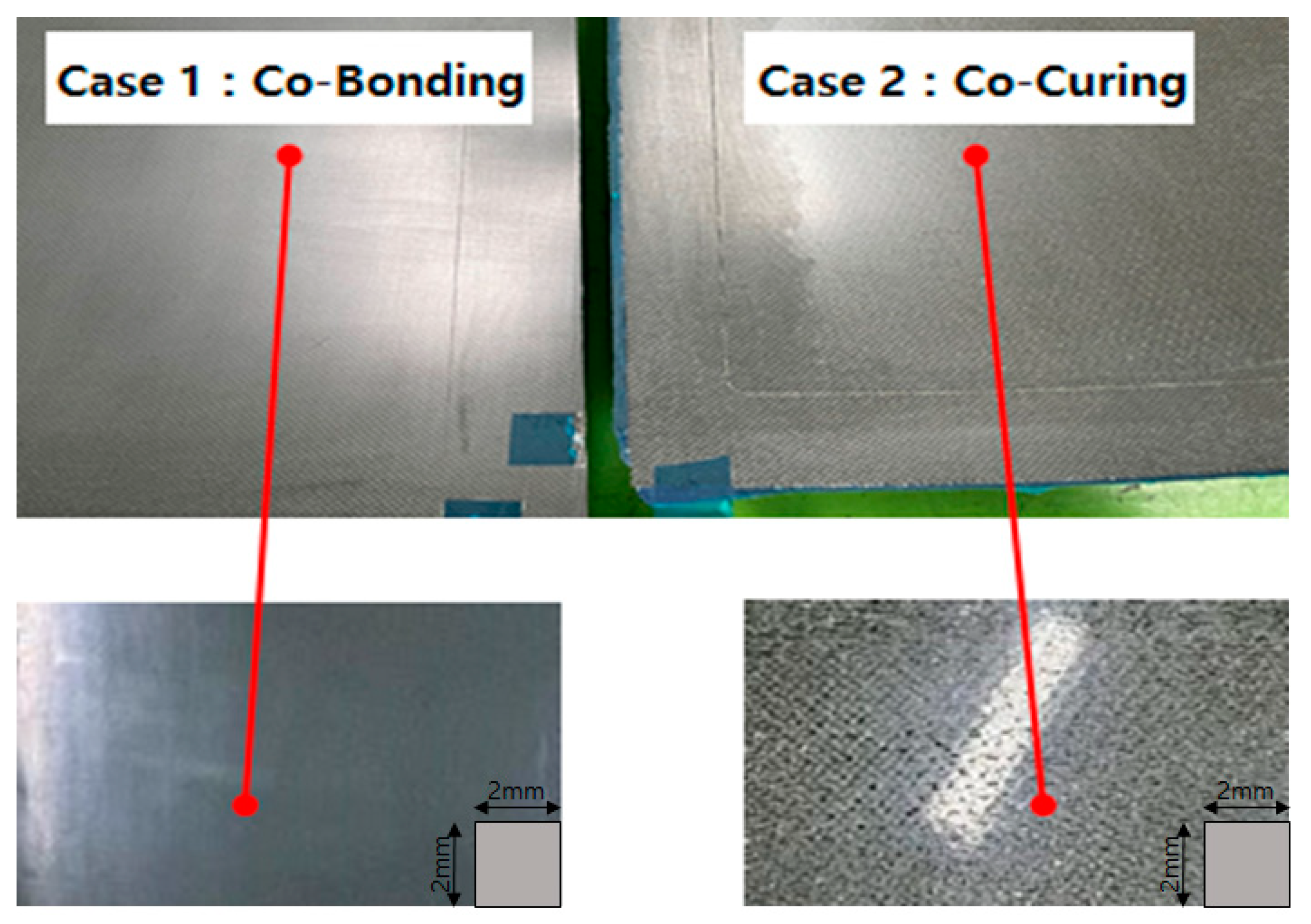
3.1. Verification of the Manufacturing of the Composite Main Reflector
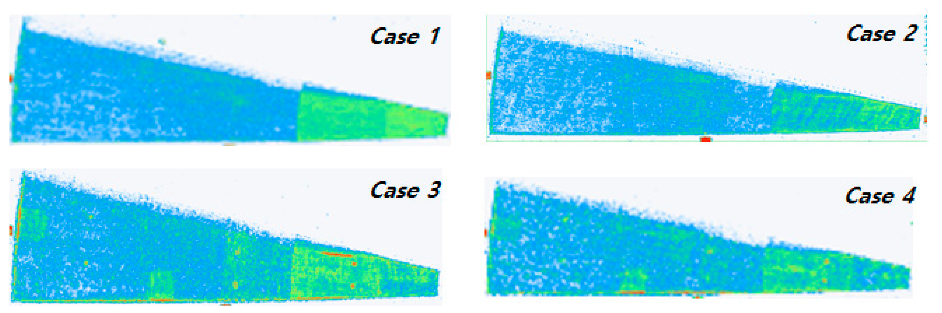
3.2. Analysis of the Surface Error of the Composite Main Reflector
3.3. Verification of the Performance of the Composite Main Reflector
3.4. Selection of Composite Main Reflector for Deployable Reflector Antenna Application
4. Conclusions
Author Contributions
Funding
Institutional Review Board Statement
Informed Consent Statement
Data Availability Statement
Conflicts of Interest
References
- Paulis, F.; Giuliomaria, D.D.; Fina, A.; Amici, M.; Mannocchi, G.; Carlofelice, A.D.; Fiaschetti, A.; Tognolatti, P.; Orlandi, A. Highly Integrated Wideband Transmit/Receive Module for X-Band SAR Applications. Appl. Sci. 2023, 13, 801. [Google Scholar] [CrossRef]
- Nasirzadehdizaji, R.; Sanli, F.B.; Abdikan, S.; Cakir, Z.; Sekertekin, A.; Ustuner, M. Sensitivity Analysis of Multi-Temporal Sentinel-1 SAR Parameters to Crop Height and Canopy Coverage. Appl. Sci. 2019, 9, 655. [Google Scholar] [CrossRef]
- Xia, Z.; Jin, S.; Yue, F.; Yang, J.; Zhang, Q.; Zhao, Z.; Zhang, C.; Gao, W.; Zhang, T.; Zhang, Y.; et al. A Novel Space-Borne High-Resolution SAR System with the Non-Uniform Hybrid Sampling Technology for Space Targets Imaging. Appl. Sci. 2022, 12, 4848. [Google Scholar] [CrossRef]
- Zhao, H.; Hao, Z.; Liu, W.; Ding, J.; Sun, Y.; Zhang, Q.; Liu, Y. The shock environment prediction of satellite in the process of satellite-rocket separation. Acta Astronaut. 2019, 159, 112–122. [Google Scholar] [CrossRef]
- Rizzo, F.; Franco, A.; Bonati, A.; Maddaloni, G.; Caterino, N.; Occhiuzzi, A. Predictive analyses for aerodynamic investigation of curtain walls. Structures 2021, 29, 1059–1077. [Google Scholar] [CrossRef]
- Maheshwaraa, U.; Bourell, D.; Conner, S.C. Design and Freeform Fabrication of Deployable Structure with Lattice Skins. Rapid Prototyp. J. 2007, 13, 213–225. [Google Scholar] [CrossRef]
- Footdale, J.N.; Jeremy, B. Design and deployment testing of the multi-arm radial composite (MARCO) reflector antenna. In Proceedings of the 3rd AIAA Spacecraft Structures Conference, San Diego, CA, USA, 4–8 January 2016. [Google Scholar]
- Petrie, G. Current & Future Spaceborne SAR Systems. In Proceedings of the International Scientific & Technical Conference, Porec, Croatia, 15–18 September 2008. [Google Scholar]
- Manfred, S.; Reiner, B. Development Summary and Test Results of a 3 Meter Unfurlable CFRP Skin Antenna Reflector. In Proceedings of the 10th European Space Mechanisms and Tribology Symposium, San Sebastian, Spain, 24–26 September 2003; pp. 145–151. [Google Scholar]
- Alberto, M.; Cicco, L.D.; Riccardo, R.; Davide, S. Large reflector technologies at TAS-1. In Proceedings of the 3rd International Conference Advanced Lightweight Structures and Reflector Antennas, Ahmedabad, India, 19–22 December 2018. [Google Scholar]
- JAXA. Epsilon Launch Vehicle User’s Manual; JAXA: Tokyo, Japan, 2016.
- ILS. Proton Launch System Mission Planner’s Guide; ILS: Moriya, Japan, 2009. [Google Scholar]
- Arianespace. Vega C User’s Manual; Arianespace: Paris, France, 2018. [Google Scholar]
- Arianespace. Ariane 6 User’s Manual; Arianespace: Paris, France, 2021. [Google Scholar]
- Kim, T.-H.; Kim, D.-Y.; Suh, J.-E.; Han, J.-H.; Lee, J.-E.; Jung, H.-Y. Vibration Analysis of SAR Antenna Reflectors During Satellite Maneuver. Korean Soc. Aeronaut. Space Sci. 2020, 48, 225–231. [Google Scholar] [CrossRef]
- Alberto, M.; Prats-Iraola, P.; Younis, M.; Krieger, G.; Hajnsek, I.; Papathanassiou, K.P. A Tutorials on Synthetic Aperture Rader. IEEE Geosci. Remote Sens. Mag. 2013, 1, 6–43. [Google Scholar]
- Kim, D.-G.; Koo, R.-K.; Kim, H.-G.; Song, S.-C.; Kwon, S.-C.; Lim, J.-H.; Kim, Y.-B. Design and Analysis of Composite Reflector of High Stable Deployable Antenna for Satellite. Compos. Res. 2023, 36, 230–240. [Google Scholar]
- Kim, H.-G.; Kim, D.-G.; Do, R.-H.; Koo, K.-R.; Yu, Y.-J. Development of Deployable Reflector Antenna for the SAR-Satellite: Part 1. Design and Analysis of the Main Reflector Using Honeycomb Sandwich Composite Structure. Appl. Sci. 2024, 14, 1590. [Google Scholar] [CrossRef]
- Yuan, C.; Li, M.; Zhang, Z.; Gu, Y. Experimental Investigation on the Co-Cure Processing of Honeycomb Structure with Self-Adhesive Prepreg. Appl. Compos. Mater. 2008, 15, 47–59. [Google Scholar] [CrossRef]
- Epstein, G.; Ruth, S. Honeycomb Sandwich Structures: Vented versus Unvented Designs for Space Systems. Aerosp. Corp. 1993. Available online: https://www.semanticscholar.org/paper/Honeycomb-Sandwich-Structures%3A-Vented-Versus-for-Epstein-Ruth/68444f47cf9a53bbebbef002a5d8ec1465efc7b4 (accessed on 28 November 2024).


| Requirement | |
|---|---|
| Mass | 100 kg class |
| 1st Freq. @ Stowed Condition | Over 33 Hz |
| 1st Freq. @ Deployed Condition | Over 2.5 Hz |
| High-Density Core | Low-Density Core | |
|---|---|---|
| Mass, Unit Main Reflector [kg/1EA] | 2.725 | 2.487 |
| Mass, Main Reflector [kg/24EA] | 65.4 | 59.69 |
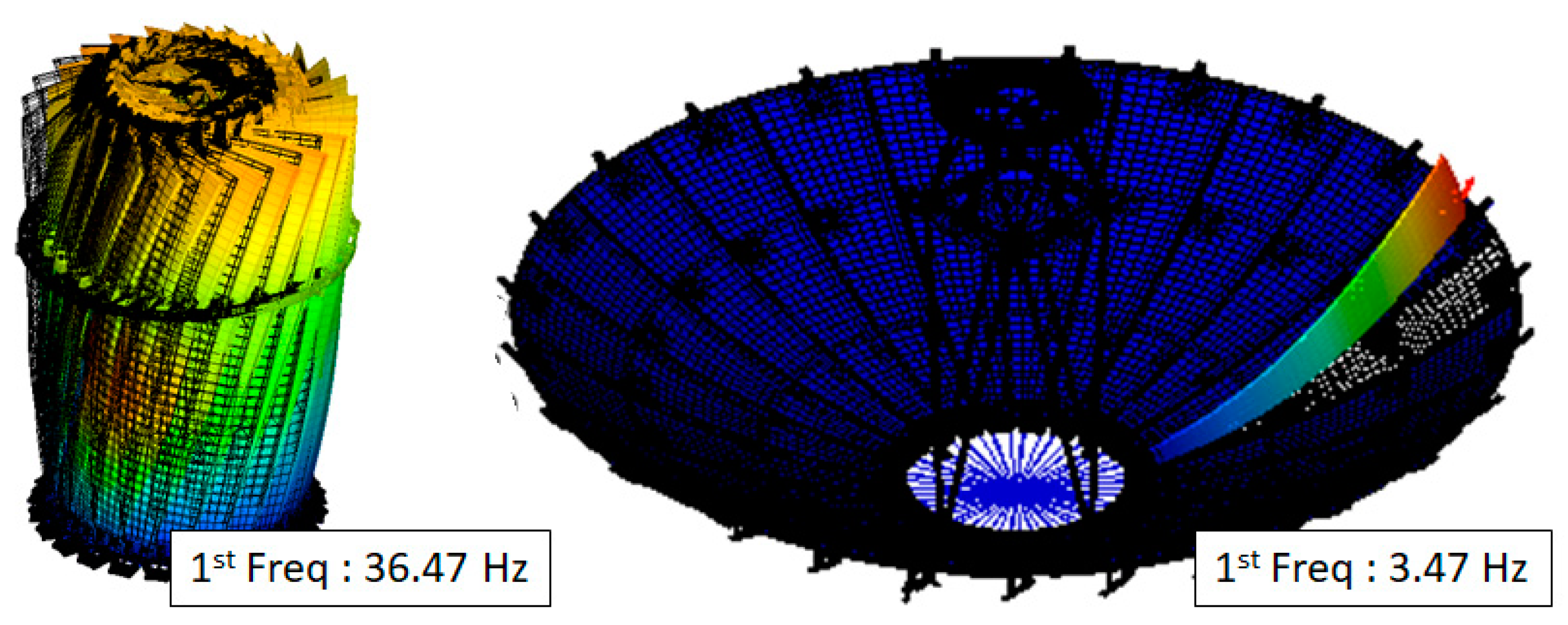
| 1st Mode Frequency [Hz] (Stowed Condition) | 35.38 | 36.47 |
| 1st Mode Frequency [Hz] (Deployed Condition) | 3.345 | 3.475 |
| Case | Curing Method | Adhesive Film | Perforated Hole | Additional Layup |
|---|---|---|---|---|
| 1 | Co-Bonding | O | X | X |
| 2 | Co-Curing | O | X | X |
| 3 | Co-Curing | X | O | X |
| 4 | Co-Curing | X | O | O |
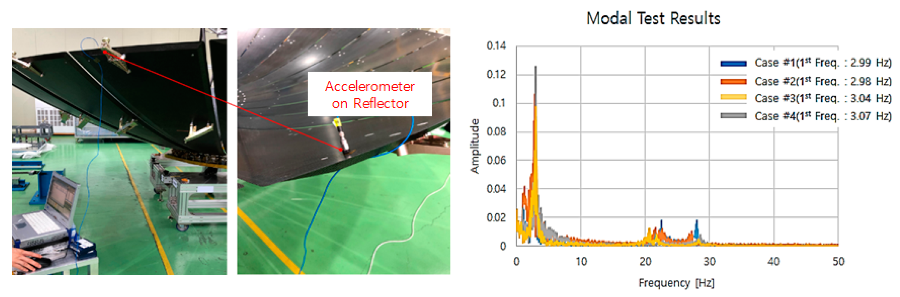
| Case | Mass [kg] | Surface Error [mm, RMS] | NDT | 1st Frequency @ Deployed Condition [Hz] |
|---|---|---|---|---|
| 1 | 1.75 | 0.387 | N/A | 2.99 |
| 2 | 1.78 | 0.393 | N/A | 2.98 |
| 3 | 1.61 | 0.290 | N/A | 3.04 |
| 4 | 1.66 | 0.325 | N/A | 3.07 |
Disclaimer/Publisher’s Note: The statements, opinions and data contained in all publications are solely those of the individual author(s) and contributor(s) and not of MDPI and/or the editor(s). MDPI and/or the editor(s) disclaim responsibility for any injury to people or property resulting from any ideas, methods, instructions or products referred to in the content. |
© 2024 by the authors. Licensee MDPI, Basel, Switzerland. This article is an open access article distributed under the terms and conditions of the Creative Commons Attribution (CC BY) license (https://creativecommons.org/licenses/by/4.0/).
Share and Cite
Kim, D.-G.; Kim, H.-G.; Kim, D.-Y.; Do, R.-H.; Koo, K.-R.; Yu, Y.-J. Development of a Deployable Reflector Antenna for the Synthetic Aperture Radar Satellite, Part 2: Manufacturing and Qualification of the Main Reflector Using a Honeycomb Sandwich Composite Structure. Appl. Sci. 2024, 14, 11273. https://doi.org/10.3390/app142311273
Kim D-G, Kim H-G, Kim D-Y, Do R-H, Koo K-R, Yu Y-J. Development of a Deployable Reflector Antenna for the Synthetic Aperture Radar Satellite, Part 2: Manufacturing and Qualification of the Main Reflector Using a Honeycomb Sandwich Composite Structure. Applied Sciences. 2024; 14(23):11273. https://doi.org/10.3390/app142311273
Chicago/Turabian StyleKim, Dong-Geon, Hyun-Guk Kim, Dong-Yeon Kim, Ryoon-Ho Do, Kyung-Rae Koo, and Young-Joon Yu. 2024. "Development of a Deployable Reflector Antenna for the Synthetic Aperture Radar Satellite, Part 2: Manufacturing and Qualification of the Main Reflector Using a Honeycomb Sandwich Composite Structure" Applied Sciences 14, no. 23: 11273. https://doi.org/10.3390/app142311273
APA StyleKim, D.-G., Kim, H.-G., Kim, D.-Y., Do, R.-H., Koo, K.-R., & Yu, Y.-J. (2024). Development of a Deployable Reflector Antenna for the Synthetic Aperture Radar Satellite, Part 2: Manufacturing and Qualification of the Main Reflector Using a Honeycomb Sandwich Composite Structure. Applied Sciences, 14(23), 11273. https://doi.org/10.3390/app142311273