Article

Computational Methodology for the Development of Wrinkled Tubes by Plastic Deformation

by
Samara C. R. Soares
1,
Gilmar C. Silva
1 and
Elza M. M. Fonseca
2,*
1
Mechanical Engineering Department, Pontifícia Universidade Católica de Minas Gerais—PUC Minas, Avenida Dom José Gaspar, 500—Campus Coração Eucarístico—CEP., Belo Horizonte 30545-901, MG, Brazil
2
Mechanical Engineering Department, School of Engineering, Polytechnic Institute of Porto, Rua Dr. António Bernardino de Almeida, 431, 4200-072 Porto, Portugal
*
Author to whom correspondence should be addressed.
Appl. Sci. 2024, 14(23), 11126; https://doi.org/10.3390/app142311126
Submission received: 21 September 2024 / Revised: 31 October 2024 / Accepted: 26 November 2024 / Published: 29 November 2024

Abstract

:
Traditional methods for wrinkled tubes involve welding processes and additional elements, such as plates, screws, rivets, and guides. Considering all the limitations of these processes, this work aims to propose a methodology that allows for maximising the manufacturing process of carbon steel tube joints with seaming using cold forming and minimising the cost of the final product. Therefore, the present work aims to develop a computational model, based on the finite element method, to optimise the deformation process of T6 Aluminium tubes (ø 45 × ø 38.6 mm) with a length of 120 mm. The method uses a steel die with cavities to achieve wrinkled tubes by a forming process. This numerical study was carried out using the Ansys® 2022 R2 software. A nonlinear material and an incremental structural analysis were used. The applied methodology allowed the optimisation of process parameters, the application of forces during tube deformation, the geometry of the die cavity, boundary conditions, and mesh discretisation. Numerical modelling was carried out using the axial symmetry of the assembly (tube–die), enabling a simplified and efficient execution of the final tube geometry. The results were analysed based on the maximum pressure applied to the tube, and the vertical and horizontal displacements of the deformed component, thus obtaining the tube flow with complete filling inside the die cavity at the end of deformation. The die geometry that produced the best results presented a cavity with a radius of curvature of 3 mm, 6 mm in height, and with a depth of 4 mm. The optimised result of the die geometry generated satisfactory results, with the displacement on the x-axis of the tube of approximately 2.85 mm, ensuring the filling of the cavity at the end of the process. For this, the maximum pressure exerted on the tube was approximately 374 MPa.

1. Introduction

Thin-walled metal tubes are widely used in naval engineering, civil construction, and the automotive sector [1]. In various applications, the tubes can be wrinkled, which can be achieved through welding processes or forming methods, depending on the specific purpose and required mechanical strength [2,3].
The welding processes have limitations related to differences in the mechanical and metallurgical properties of materials [4,5]. Threaded, pressed, welded, brazed, or bonded connections are commonly used to join the ends of tubes. Threaded connections are simple to design, easy to assemble and disassemble, and come in standard sizes [6]. Another option is the use of pressure in the fitting, which is not limited by aesthetic requirements, flanges, or standard sizes, but may be constrained by the required extraction force and water or gas tightness [7]. Bonded joints are alternatives to welded joints in situations where high temperatures are not applicable or when different materials (such as metals and polymers) are used [8].
Adhesive joints eliminate most of the limitations associated with other types of joints. Still, they require careful surface preparation with tight tolerances, and the curing time of the adhesive must also be considered [9].
Mechanical forming techniques have increasingly been used to minimise these limitations in manufacturing wrinkled tubes [10]. Given their commercial importance and wide range of applications, extensive research has been conducted on these processes. Key evaluation parameters include the energy absorbed during the process, the stress exerted during deformation, and changes in mechanical properties in areas where dimensional and geometric alterations occur in the formed structure. Wrinkled tubes obtained by sheets are presented in [11] as one of the innovative joining processes. According to the authors, the challenges for current and future engineers are obtaining mechanical joints with ultra-high-strength steels and applying materials with greater property dispersion (mechanical and geometric properties, including sheet thickness), which require more flexible and robust processes [12]. Studies are focused on optimising structures, geometries, and the amount of material required for tube manufacturing, as well as reducing failures that occur during the process, such as bends, cracks, impact analysis, and the resistance of the materials used [13,14].
An example is the study of the effect of diameter expansion methods on the bending fracture resistance of Fe-SMA tube joints at various strain rates. The authors investigated the following methods for expanding the diameter of Fe-SMA joints: radial tube expansion, and unidirectional and bidirectional imposed pressure. The joints obtained were tested, and their bending fracture resistance was evaluated [15]. Currently, research is being conducted on aluminium tube joining processes using plastic forming. The study conducted in [16,17] discusses experimental tests with tools designed to create the most suitable joints for tube joining using the tube expansion principle, to position the contact surfaces of the two tubes adequately for subsequent joining, which is achieved through plastic instability and simultaneous pressure flanging. One of the main objectives of this study was to determine appropriate joining parameters, such as tool distance or edge conicity, for further investigations [16,17].
However, there is still a lack of research that combines numerical studies with experimental testing of wrinkled tubes or other tube-joining processes aiming to optimise the process and its parameters, particularly with the detailed methodology for the numerical study and optimised dimensions in die geometry. To reduce the number of experimental tests, production costs, and design expenses, numerical simulations have been applied to solve technical problems [18]. In [19], numerical modelling was performed to evaluate the metal flow during the mechanical forming of tubes, as well as the optimisation and selection of reasonable modelling steps to avoid defects due to instability and inadequate die design. Joining steel tubes to a thin sheet was modelled by [20], aiming to obtain the joint both numerically and experimentally, comparing the final dimensions of the joint and testing the structure to ensure it could withstand torsional loads, given its primary application in scaffolding and ladders.
Numerical studies applied to manufacturing processes are becoming increasingly essential to optimise processes, final dimensions of structures, and die geometry [21,22]. The use of numerical simulations in forming processes allows for the analysis of deformations, defects, and failures, as well as changes in process parameters [23]. The final geometry and variations in mechanical properties can be predicted throughout the process, and parameters can be adjusted to make the process more productive, reducing costs and manufacturing errors. According to [24,25], numerical optimisation and simulation are crucial, not only for finding an optimal process design for a given material but also for finding the most accurate material model for a specific problem. In this study, mesh refinement was applied to obtain more accurate results for stresses and displacements.
This work aims to present the methodology applied in the numerical simulation of the deformation of an Al 6061-T6 aluminium wrinkle tube. In addition to modelling the plastic deformation process of the tube so that it flows into the die cavities and fills them, the die geometry optimisation was important to ensure the correct shape of the die, using less material for production and reducing the occurrence of manufacturing defects during the forming process [26,27]. The simulation that was performed aims to obtain the final geometry of the wrinkled tube after plastic deformation. This type of sheet-to-tube joint design eliminates the need for welding or mechanical fasteners, which is a major advantage of the manufacturing process and its application.

2. State-of-the-Art: Wrinkled Tube in Metal Sheets by Forming

To meet recent demands for manufacturing technologies involving the joining of tubes through the forming of industrial and engineering components, the current state-of-the-art aims to overcome inherent process limitations and optimise manufacturing parameters as well as die geometrical tubes.
Researcher Alves et al. [28], in 2021, presented a new method for joining sheets to tubes by creating a single-turn flange by compressing the free end of the tube using a die. The deformation of the tube forms a flange that can be pressed against the metal sheet, ensuring the assembly joint without the need for additional surface preparation or machining grooves into the sheet holes.
Addressing the challenges of traditional tube joining processes, such as welding or the use of pins and bolts, hydroforming was studied in 2022 by [29]. The process involves axial compression that induces buckling/folding in the tube, followed by joining with the sheet. The tube is pressurised with low pressure, along with the application of an axial force that deforms the tube outward and around the sheet. After this step, the buckled region is compressed to create the joint.
In 2023, one of the innovations in the literature was electromagnetic forming (EMF) joining, especially for lightweight components in the automotive and aerospace industries. The advantage of this process lies in its ability to join dissimilar materials. The paper titled “Joining by Electromagnetic Forming” provides a comprehensive review of the EMF process, particularly focusing on its application in joining operations [30].
Among the challenges related to obtaining tube-to-sheet joints is the occurrence of protrusions or notches near the joints, which can compromise the structural integrity and lead to the deformation of the involved plates. To prevent warping of the sheets during the application of forces, in 2023, the authors in [31] proposed a new joining process by forming and compressing an accessory ring to produce annular compression of the sheet, thus forming high-quality joints with smooth surfaces. In this study, the effects of process parameters such as the height and width of the ring, tube thickness, and flow velocity on the joint behaviour were analysed.
Further addressing the complexity of parameters, in [32] the authors investigated the interference-fit joining of aluminium alloy tubes with mandrels made of different materials and manufactured under various metallurgical conditions. They discuss the effects of initial clearance, surface roughness, and material properties on the process. These parameters have a direct relationship with the residual stress in the mandrel, the joint area, and the interfacial friction coefficient between the tube and the mandrel.

3. Materials and Methods

3.1. Mathematical Model

This work presents the geometry optimisation, the process parameters, and boundary conditions needed for use in the numerical simulation for the deformation of an Al 6061-T6 aluminium wrinkled tube with an external diameter of 42.6 mm, a thickness of 3.2 mm, and a length of 120 mm. The objective is to model the plastic deformation process of the tube so that it flows into the cavity of the die, filling it. Figure 1 shows (a) the drawing of the die and the tube for the present numerical study and (b) the initial geometry of the components and the assembly of the die and tube before deformation. The mathematical model, using the finite element method, aims to optimise the process parameters required to obtain the wrinkled tube.
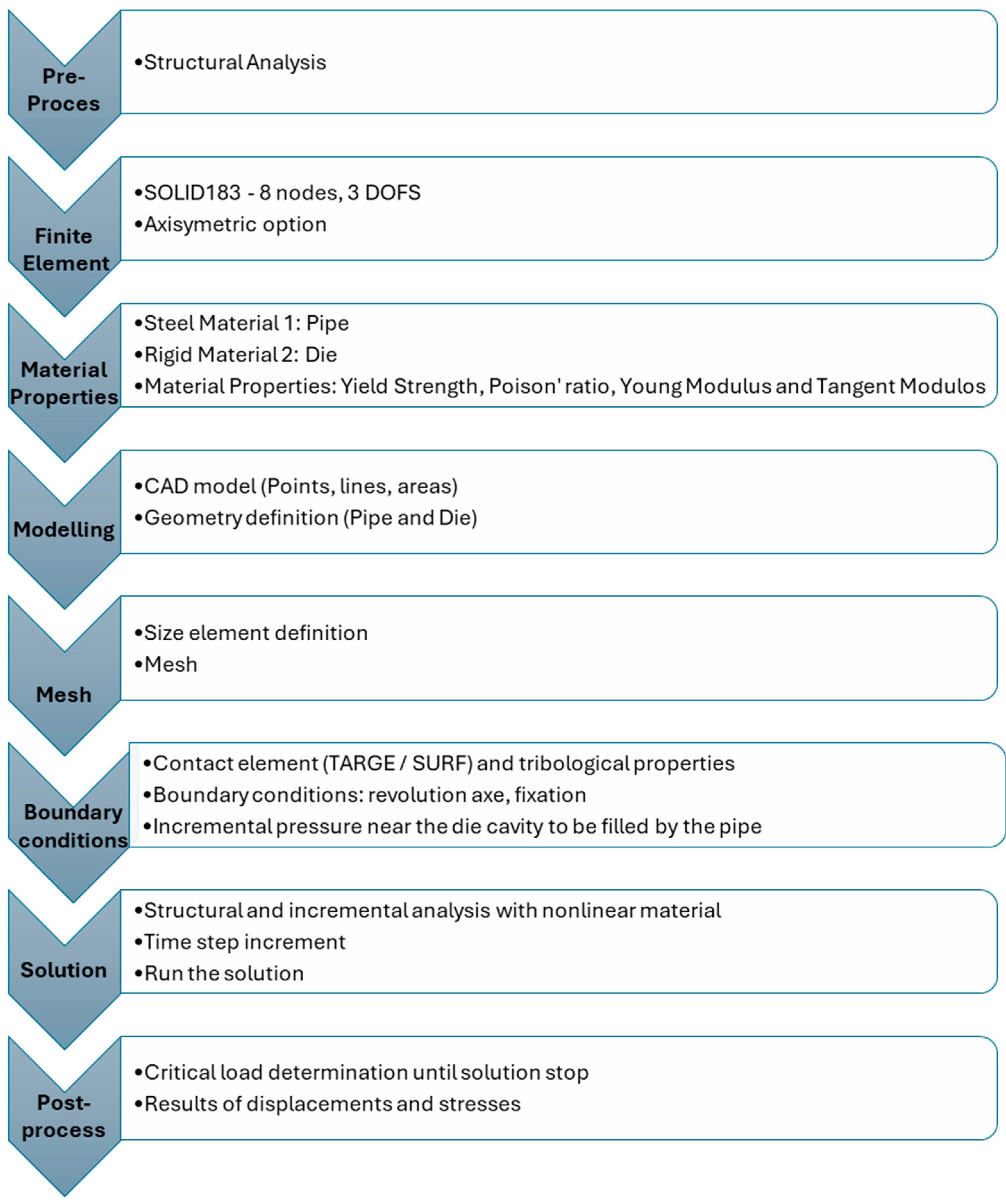
The numerical models were constructed in Ansys® 2022 R2 Parametric Design Language (APDL)/2D. The analysis of the numerical model was based on the Finite Element Method (FEM), using the same geometric and mechanical properties as the experimental models. The methodology adopted for the numerical work consisted of the steps presented in the flowchart in Figure 2.

3.1.1. Pre-Processing

A structural analysis was defined for the problem under investigation. The chosen finite element was Plane 183, a 2D element with 8 nodes and two degrees of freedom per node: translations occur in the x and y nodal directions. The proposed element is suitable for axisymmetric analyses and has sufficient degrees of freedom to represent the deformation effects to which the structure is subjected. The model geometry was pre-designed in two dimensions, considering the parts of the assembly with an axisymmetric shape, as the model has symmetry throughout its extent. This approach reduced simulation time and simplified the analysis, optimising the process.
To obtain the most accurate results possible, the mechanical properties of the tube and die material were provided in both linear and nonlinear deformation regimes. For elastic behaviour, the mechanical properties adopted for the aluminium tube were Young’s Modulus and Poisson’s Ratio, respectively, 69 GPa and 0.3. For the nonlinear, elastoplastic regime, yield stress and tangent modulus values were 280 MPa and 100 MPa, respectively [33]. Concerning the die, although modelled as a deformable structure, a Young’s Modulus value of 69,000 GPa was adopted to ensure that it was rigid. The yield stress was also significantly increased to 600 MPa. The Poisson’s Ratio and tangent modulus values were like those applied to the tube. Initially, a mesh sensitivity analysis and result convergence were conducted. The element sizes created for the analyses were 2 mm, 1.5 mm, and 1 mm, always meeting the tube thickness value of 3.2 mm.
Figure 2. Flowchart of the numerical modelling for tube deformation by mechanical forming.
Applsci 14 11126 g002

3.1.2. Boundary Conditions

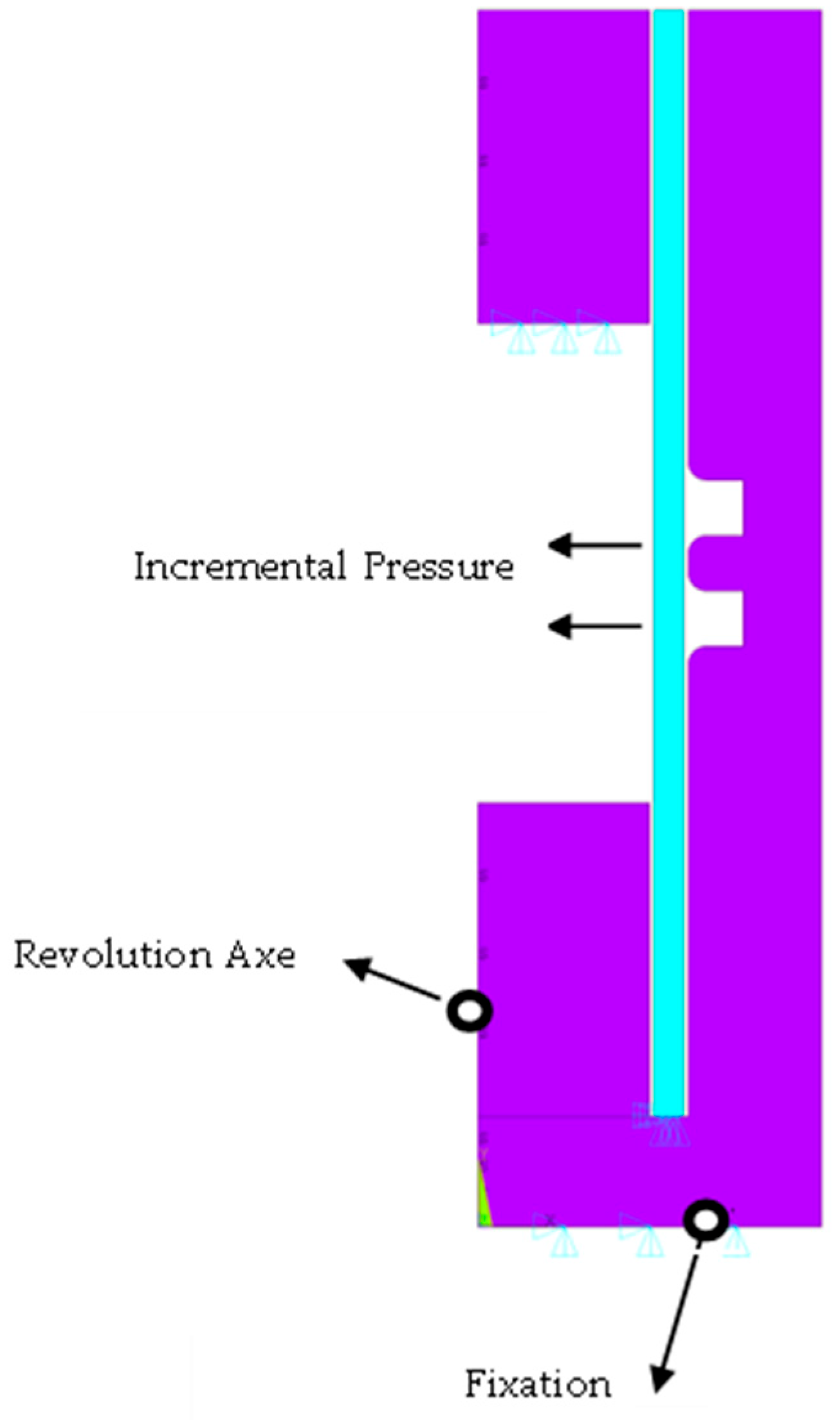
The boundary conditions adopted in this mathematical model of the wrinkled tube were the contact lines between the tube and the die, creation of symmetry axes, fixation of die lines to constrain displacement, and application of pressure on the inner walls of the tube.
(a)
Contact Lines
To ensure the most accurate tribological behaviour, contact surfaces were created between the outer wall of the tube and the inner wall of the die. The die was defined as the Target and the tube as the contact. For the tube/die pair, a friction coefficient of 0.15 [34] was adopted, which is a conventional coefficient for metal forming. At this stage, some parameters were also defined to control the penetration of elements in the contact regions, to ensure modelling without interruptions or divergences in the deformation of the tube.
(b)
Axis of Symmetry, Fixation, and Applied Loads
The axis of symmetry and the fixation points with restrictions in all degrees of freedom were created during the structural loading definition stage. Structural loading on the tube was applied as pressure in the central region in each cavity of the die, based on an incremental value. This loading was defined due to the non-localised nature of the force applied during the tube deformation process; it was applied along the entire circumferential extent of the tube and at the upper end of the tube. The maximum pressure considered was 150 MPa, referencing the interference fit-joining work for tube crimping on mandrels from [35].
Figure 3 shows the regions where these loads were applied.
After following these steps in the numerical simulation methodology, a structural analysis was selected, defining it as a nonlinear material and incremental time analysis with large displacements for the numerical solution.

4. Results and Discussion

The initial results obtained from the numerical simulation of the aluminium wrinkled tube, due to incremental loading around the tube circumference, were the mesh convergence criteria, with variations in the mesh size; the von Mises stresses; and the cavity filling of the die after the total deformation of the tube.

4.1. Die Geometry Convergence

Initially, the die was designed with two cavities for the double deformation of the tube. In this model, only the deformation of the tube was analysed while filling the die cavities; therefore, the sheet to be joined to the tube was not considered.
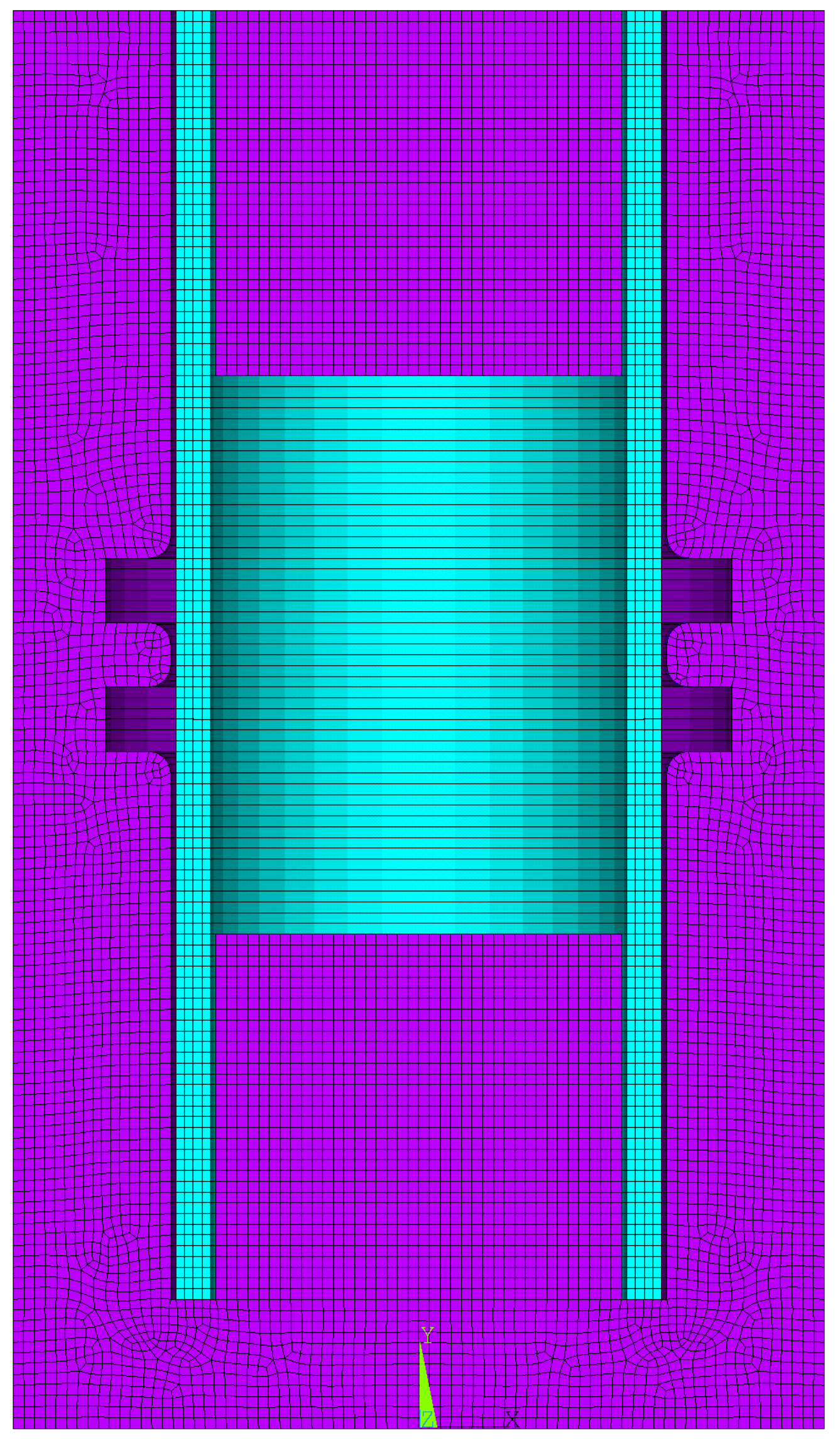
For practical tests, the space for joining the sheet to the tube must be considered. The cavities were designed with a convergence radius of 2 mm, a height of 6 mm, and a depth of 6 mm, as shown in Figure 4.

4.2. Results of Von Mises Stresses

The discretisation with an element size of 2 mm generated 1489 elements, while the 1.5 mm size generated 2594 elements. Finally, the 1 mm mesh generated 8078 elements. It can be observed that the die shows greater variation in discretisation due to its larger dimensions, while in the tube, due to its geometry, there were variations only in the number of elements. It is important to note that mesh refinement reduces element distortion in the simulation and produces more accurate results.
After analysing the mesh sensitivity, deformation of the tube was observed and results were obtained regarding von Mises stresses, as shown in Figure 5. As expected, only the tube underwent deformation, given the higher stiffness imposed on the die to ensure its rigidity.
Discretisation with 1 mm element sizes generated better results, both in the final deformation of the tube and in the maximum stresses applied during the simulated process. Therefore, subsequent analyses were conducted considering only this optimised model.
According to [36], mesh refinements in numerical simulations present challenges such as computational cost, occurrence of distortions, and degeneration of elements. However, the mesh sensitivity study conducted in this work produced satisfactory results, as it highlighted the best outcomes and greater accuracy for the tube filling the die cavities during deformation.
The values of the maximum pressure applied during the process were sensitive to mesh refinement, as expected [37].

4.3. Maximum Pressure and Displacements of the Tube

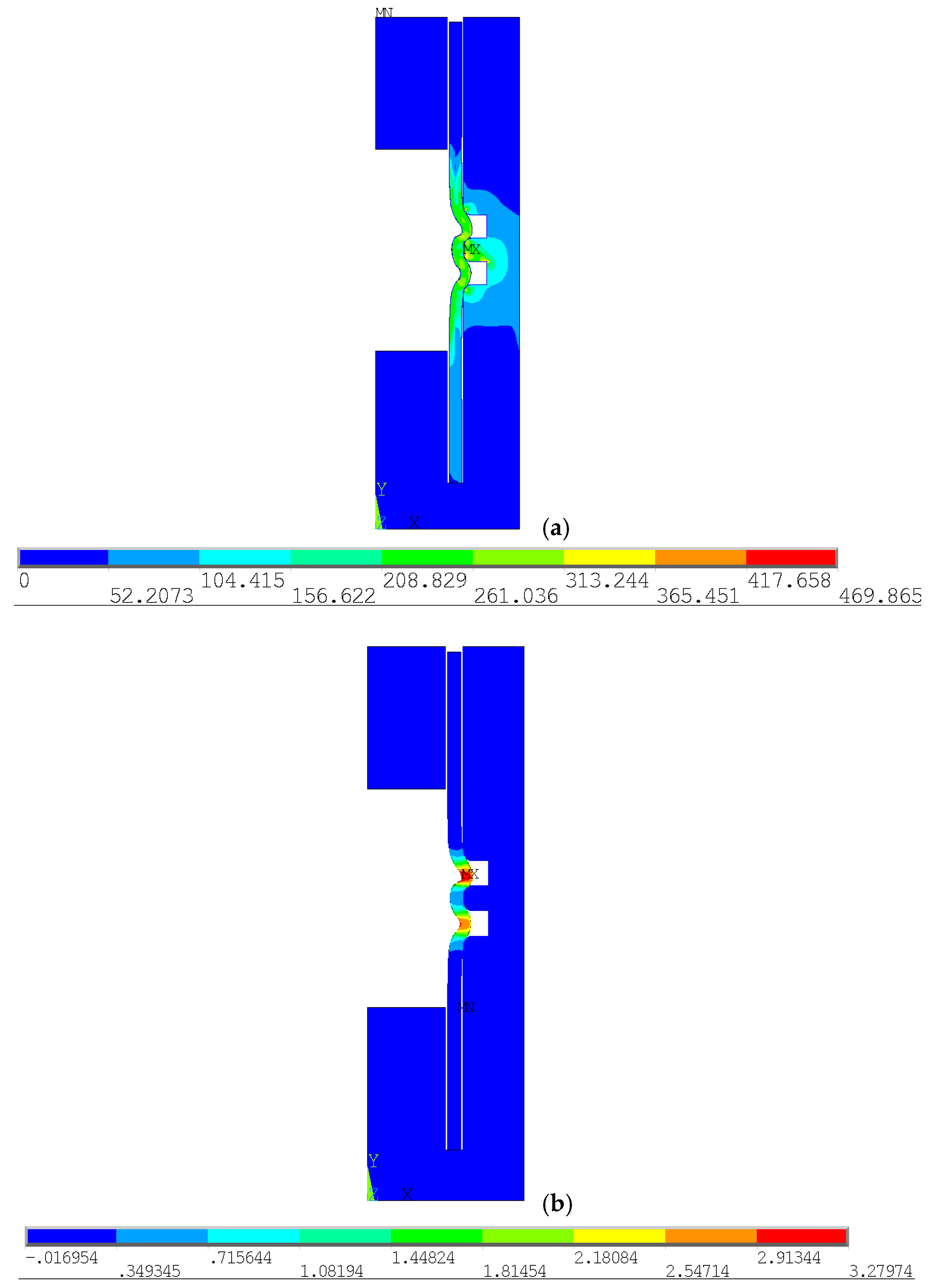
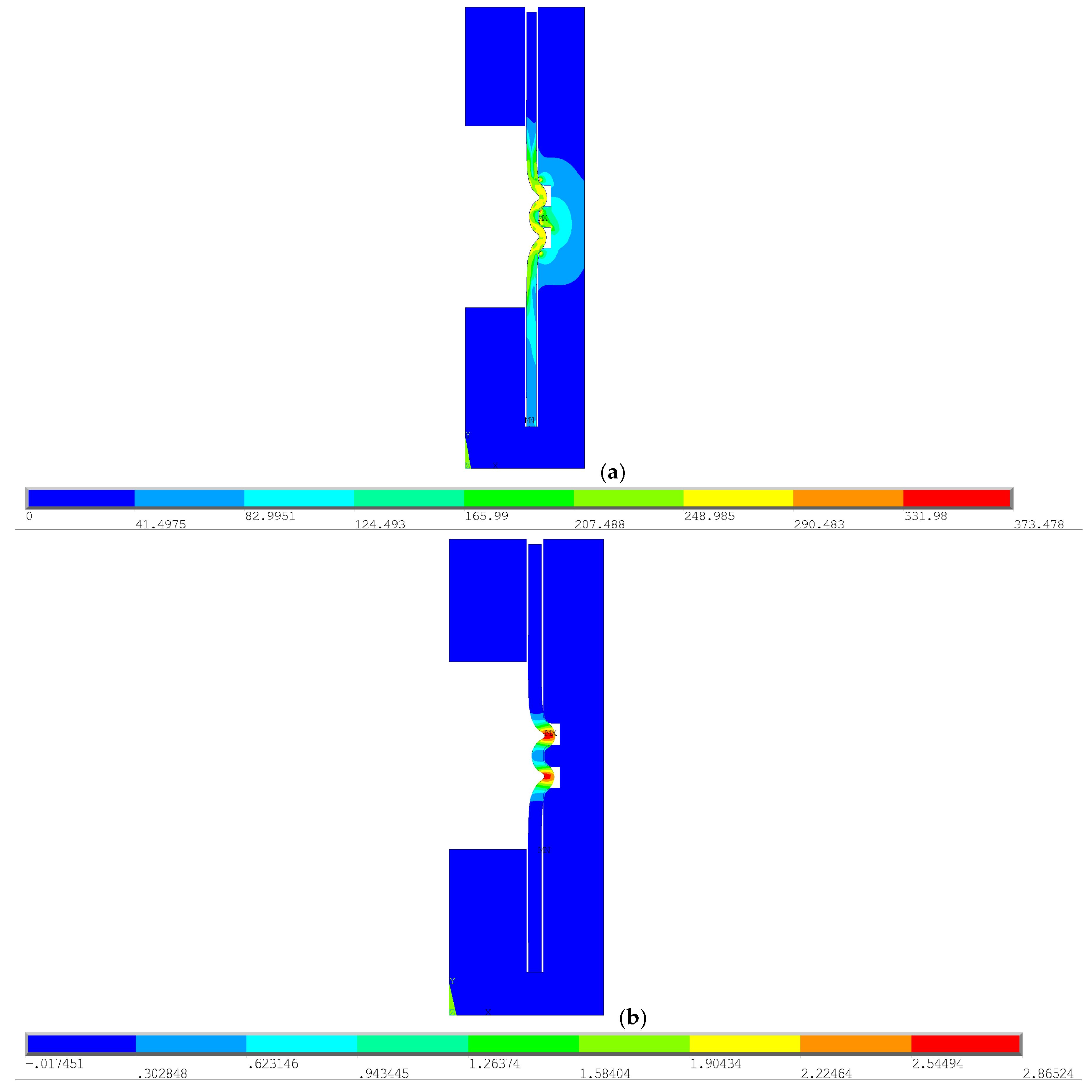
The von Mises stress values and the vertical and horizontal displacements of the tube after deformation were obtained from the model generated during mesh development. The horizontal displacement was analysed in the central region of the cavity, while the vertical displacement was assessed from a central region of the tube’s thickness. Figure 6 and Table 1 show the results on an actual scale.
The result demonstrated satisfactory tube deformation, as the tube was deformed similarly in both cavities and flowed into the cavities effectively. This allowed us to obtain the wrinkled tube. However, as the goal was to optimise both the die geometry and the process parameters, the cavity was not filled to its full depth. So, for a reduction in this dimension and to better utilise the die geometry and facilitate the plastic conformation of the tube, more numerical tests were produced.
Therefore, a new die dimension was modelled to ensure that the cavities were filled and to generate a more accurate and optimised result. The shape and dimensions of the internal cavity of the die are key factors in ensuring contact between the tube and the die during the tube-forming process, affecting the flow and deformation conditions of the materials [38]. In the new model, the cavity depth was set to 4 mm, justified as it is the closest integer value to the maximum displacement of the tube elements along the x-axis after deformation in both cavities. The results for von Mises stress, and horizontal and vertical displacements, are presented in Figure 7 and Table 2.
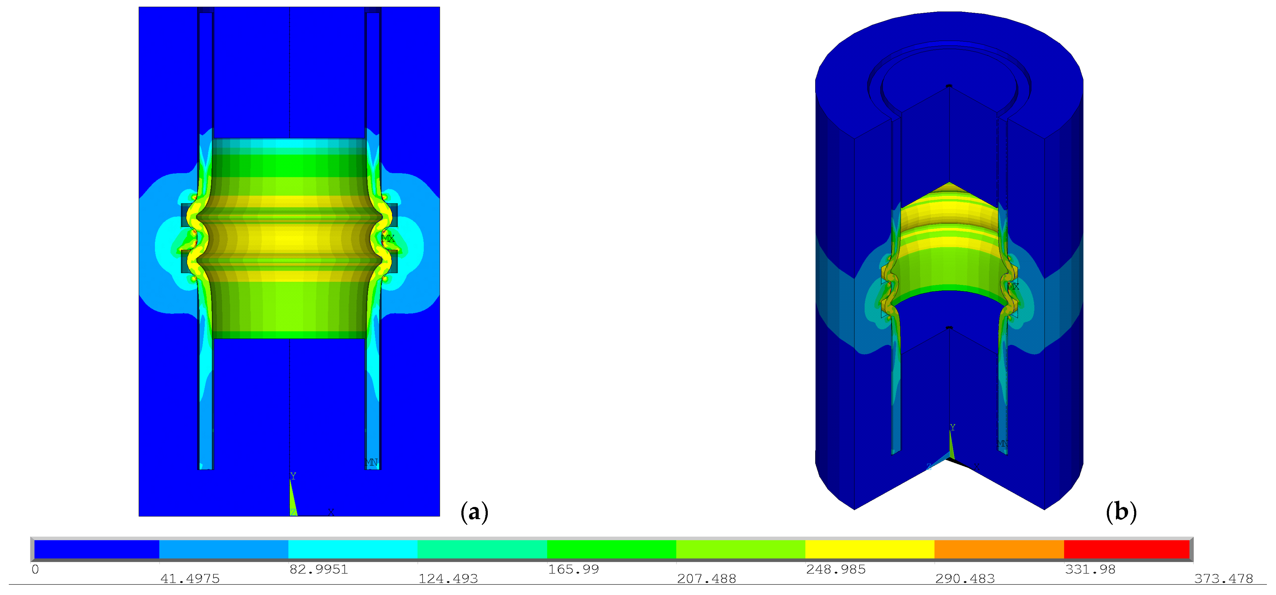
Finally, this model ensured that the die cavity was filled after the full deformation of the tube and produced an optimised result for the die geometry and simulation parameters. For clearer visualisation of the results, Figure 8 presents: (a) a ½ expansion view of the assembly, and (b) a ¾ expansion view of the model after tube deformation and filling of the die cavities.

4.4. Applications and Experimental Tests

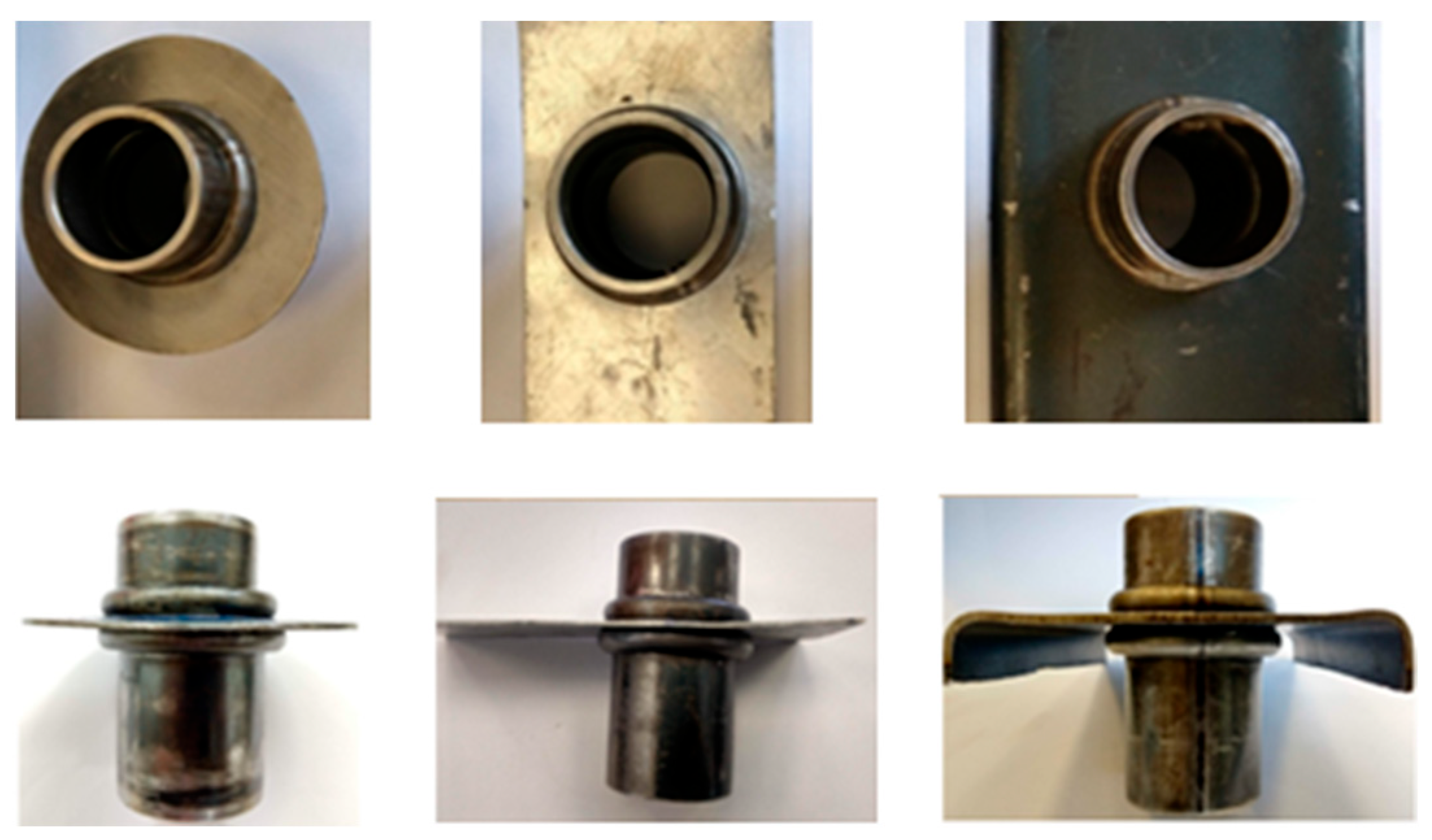
The wrinkled tube modelled according to the methodology presented in this work has applications in structural components, such as scaffolding, ladders, and gym equipment. The tube can be in other different materials, including steel or aluminium. Figure 9 shows three wrinkled tubes in steel and aluminium material.
Considering the potential applications, such as in scaffolding systems, the study of rotational stiffness prevents operational failures, ensuring safety during load application [39]. Analysing the forces acting on these systems reduces uncertainties in projects of this nature by ensuring control over the stiffness of component joints and the mechanical properties of their materials.
In the research of co-authors [20] involved in the present work, a wrinkled tube was experimentally obtained using a hydraulic press, and the practical test setup consisted of interchangeable dies with an internal cavity for the insertion of the tube. After working the tube joint into a thin sheet, hardness tests were performed along the deformed regions of the tube to analyse the variation in this property and the variation in grain size in the deformed regions. Finally, a torsion test was conducted on the final designed part to assess the torque resisted by the joint.
The numerically modelled wrinkled tube in this work also allows for the analysis of mechanical properties effect in the applicability tests to validate the model. The joints can be referenced for practical analyses, as the experimental test methodology is similar, as well as the final geometry of the tube. The proposal presented here aims to expand and enrich the mathematical modelling work, with the use of software emerging as an essential tool, allowing for the study of forming processes by varying the parameters and the dimensional and mechanical characteristics of the tested tubes, in addition to enabling studies of the materials during and after forming.
Our published work [20], with the experimental methodology applied to this type of tube, allows us to conclude that the wrinkled tube in the front view presented values equal to 6.9 and 6.1 mm, after the cold forming process was used for joining tubes to sheets, as can been seen in Figure 9. These values are comparable with those obtained from the numerical methodology proposed in the present work. The geometry used in this study, Figure 1, already considers this dimension for the die cavity equal to 6 mm. The objective was to fill this cavity, obtaining the wrinkled tube through the proposed simulation, and represented as the final solution in Figure 8 close to the experimental process.

5. Conclusions

The objective of this work was to numerically simulate the deformation of T6 aluminium tubes. Internal pressure was applied to the inner surface of the tube to obtain the final geometry after deformation and cavity filling of the die. The analysis was performed on structural, nonlinear material, and was incremental, considering the die with high stiffness. The application of pressure inside the tube yielded the best results, concentrating the deformations in regions that facilitated the flow of the tube into the die cavities. The reduction in cavity length and the addition of a flat region between the curvature radii also produced the best results, ensuring a more uniform and complete filling of the die cavities after tube deformation.
In conclusion, this work was completed as expected, close to the experimental prototype deformation, where the geometry of the tube was numerically achieved after optimising both parameters and boundary conditions, as well as the die geometry. The proposed methodology for obtaining a wrinkled tube, a function of the die geometry, is significant for practical industrial applications.
Future work should include the analysis of a three-dimensional model for explicit dynamic analysis based on the two-dimensional model, considering the nonlinearities present in the tube during deformation, such as elastoplasticity and large displacements. In addition, the comparison of numerical results with new experimental test prototypes, as suggested in [34], will be important for optimising the required force in the open-die tube forming process.

Author Contributions

Conceptualization, E.M.M.F.; methodology, S.C.R.S.; validation, S.C.R.S.; investigation, S.C.R.S.; writing—original draft preparation, S.C.R.S.; writing—review and editing, E.M.M.F. and G.C.S.; supervision, G.C.S. All authors have read and agreed to the published version of the manuscript.

Funding

This work was carried out with the support of Coordination for the Improvement of Higher Education Personnel-Brazil (CAPES)-Financing Code 001.

Institutional Review Board Statement

Not applicable.

Informed Consent Statement

Not applicable.

Data Availability Statement

Data are contained within the article.

Acknowledgments

The authors thank PUC MINAS and the School of Engineering, Polytechnic Institute of Porto, for their contribution to the preparation of this article by making equipment, services and materials available.

Conflicts of Interest

The authors declare no conflicts of interest.

References

  1. Bell, C.; Corney, J.; Zuelli, N.; Savings, D. A state-of-the-art review of hydroforming technology. Int. J. Mater. Form. 2020, 13, 789–828. [Google Scholar] [CrossRef]
  2. Liu, Y.X.; Qiu, X.; Wang, W.; Yu, T.X. An improved two-arcs deformational theoretical model of the expansion tubes. Int. J. Mech. Sci. 2017, 133, 240–250. [Google Scholar] [CrossRef]
  3. Meraz, M.; Kumar, M.; Singh, R.P. Experimental Study of Hydroformed Al6061T4 Elliptical Tube Samples under Different Internal Pressures. EMITTER Int. J. Eng. Technol. 2022, 10, 351–369. [Google Scholar] [CrossRef]
  4. Vyas, H.D.; Mehta, K.P.; Badheka, V.; Doshi, B. Friction welding of dissimilar joints copper-stainless steel pipe consist of 0.06 wall thickness to pipe diameter ratio. J. Manuf. Process 2021, 68, 1176–1190. [Google Scholar] [CrossRef]
  5. Alves, L.M.; Dias, E.J.; Martins, P.A.F. Joining sheet panels to thin-walled tubular profiles by tube end forming. J. Clean. Prod. 2011, 19, 712–719. [Google Scholar] [CrossRef]
  6. Huang, J.; Liu, J.; Gong, H.; Deng, X. A comprehensive review of loosening detection methods for threaded fasteners. Mech. Syst. Signal Process 2022, 168, 108652. [Google Scholar] [CrossRef]
  7. Yuan, S.J.; Cui, X.-L.; Wang, X.S. Investigation into wrinkling behavior of thin-walled 5A02 aluminum alloy tubes under internal and external pressure. Int. J. Mech. Sci. 2015, 92, 245–258. [Google Scholar] [CrossRef]
  8. Budynas, R.G.; Nisbett, J.K. Shigley’s Mechanical Engineering Design; McGraw Hill: New York, NY, USA, 2008; ISBN 0071268960. [Google Scholar]
  9. Miller, G.G. Tube Forming Processes: A Comprehensive Guide; Society of Manufacturing Engineers: Southfield, MI, USA, 2003; ISBN 9780872636330. [Google Scholar]
  10. Wang, X.S.; Cui, X.L.; Yuan, S.J. Research on flattening behavior of wrinkled 5A02 aluminum alloy tubes under internal pressure. Int. J. Adv. Manuf. Technol. 2016, 87, 1159–1167. [Google Scholar] [CrossRef]
  11. Buffa, G.; Fratini, L.; La Commare, U.; Römisch, D.; Wiesenmayer, S.; Wituschek, S.; Merklein, M. Joining by forming technologies: Current solutions and future trends. Int. J. Mater. Form. 2022, 15, 27. [Google Scholar] [CrossRef]
  12. Alves, L.M.; Afonso, R.M.; Martins, P.A.F. Double-sided self-pierce riveting. Int. J. Adv. Manuf. Technol. 2020, 108, 1541–1549. [Google Scholar] [CrossRef]
  13. Gupta, P.K. Numerical Investigation of Process Parameters on External Inversion of Thin-Walled Tubes. J. Mater. Eng. Perform. 2014, 23, 2905–2917. [Google Scholar] [CrossRef]
  14. Hwang, Y.-M.; Pham, H.-N.; Tsui, H.-S.R. Investigation of Punch Shape and Loading Path Design in Hydro-Flanging Processes of Aluminum Alloy Tubes. Metals 2021, 11, 636. [Google Scholar] [CrossRef]
  15. Cao, B.; Sun, Q.; Iwamoto, T. Bending fracture strength of the pipe joint using iron-based shape memory alloy (Fe-SMA) subjected to different expansion methods at various deformation rates. Eng. Struct. 2022, 267, 114669. [Google Scholar] [CrossRef]
  16. Zhu, Q.-Q.; Huang, S.; Wang, D.-X.; Li, J.-P.; Hua, F.-A.; Yang, P. Numerical simulation and experimental study of warm hydro-forming of magnesium alloy sheet. J. Manuf. Process 2022, 80, 43–53. [Google Scholar] [CrossRef]
  17. Kovács, P.Z. Joining of EN AW 6060 Pipes by Plastic Forming. Period. Polytech. Mech. Eng. 2024, 68, 31–37. [Google Scholar] [CrossRef]
  18. Du, B.; Zhao, C.; Dong, G.; Bi, J. FEM-DEM coupling analysis for solid granule medium forming new technology. J. Mater. Process. Technol. 2017, 249, 108–117. [Google Scholar] [CrossRef]
  19. Le, T.-K.; Bui, T.-A. Cold Forging Effect on the Microstructure of Motorbike Shock Absorbers Fabricated by Tube Forming in a Closed Die. Appl. Sci. 2021, 11, 2142. [Google Scholar] [CrossRef]
  20. Silva, G.C.; Soares, S.C.R.; Vieira, A.L. Pipe joining by mechanical conformation in thin sheets with rotary locking via a notch. Eng. Struct. 2021, 249, 113151. [Google Scholar] [CrossRef]
  21. Falk, T.; Jakel, M. Increasing flexibility of self-pierce riveting using numerical and statistical methods. Procedia Manuf. 2019, 29, 264–270. [Google Scholar] [CrossRef]
  22. Ghosh, S.; Kikuchi, N. Finite element formulation for the simulation of hot sheet metal forming processes. Int. J. Eng. Sci. 1988, 26, 143–161. [Google Scholar] [CrossRef]
  23. Antônio, A.C.; Sam, C.; Matteo, S. Optimization and inverse analysis in metal forming: Scientific state-of-the-art and recent trends. Int. J. Mater. Form. 2022, 15, 44. [Google Scholar] [CrossRef]
  24. Pepelnjak, T.; Gantar, G.; Kuzman, K. Numerical simulations in optimisation of product and forming process. J. Mater. Proc. Technol. 2011, 115, 122–126. [Google Scholar] [CrossRef]
  25. Starman, G.; Cafuta, G.; Mole, N. A Method for Simultaneous Optimization of Blank Shape and Forming Tool Geometry in Sheet Metal Forming Simulations. Metals 2021, 11, 544. [Google Scholar] [CrossRef]
  26. Van, D.D.; Vu, D.Q. Investigation on Billets and Tools Geometry in Cold Forging of the Straight Bevel Gear. Int. J. Adv. Sci. Eng. Inform. Technol. 2022, 12, 867–872. [Google Scholar] [CrossRef]
  27. Wu, W.; Zeng, T.; Hao, W.; Jiang, S. Microstructure and Mechanical Properties of Aluminum Matrix Composites Reinforced with In-Situ TiB2 Particles. Front. Mater. 2022, 9, 817376. [Google Scholar] [CrossRef]
  28. Alves, L.M.; Afonso, R.M.; Martins, P.A.F. A new deformation assisted tube-to-tubesheet joining process. Thin-Walled Struct. 2021, 163, 107784. [Google Scholar] [CrossRef]
  29. Memon, S.; Nikhare, C.P. Investigation of tube sheet joining through hydroforging process. In Proceedings of the ASME International Mechanical Engineering Congress and Exposition (IMECE) (Advanced Manufacturing Article V02AT02A052), Columbus, OH, USA, 30 October–3 November 2022; American Society of Mechanical Engineers (ASME): New York, NY, USA, 2022; Volume 2. [Google Scholar] [CrossRef]
  30. Geier, M.; Paese, E.; dos Santos, T.; Homrich, R.P.; Rosa, P.; Rossi, R. Joining by electromagnetic forming. Compr. Mater. Process. 2023, 3, 316–333. [Google Scholar] [CrossRef]
  31. Wang, P.; Jin, J.; Afonso, R.M.; Wang, Y.; Zhang, C.; Xiang, N.; Wang, X.; Zhao, X. A novel mechanical joining method for sheet-tube structures by annular ring compression. Thin-Walled Struct. 2023, 191, 111031. [Google Scholar] [CrossRef]
  32. Geier, M.; José, M.M.; Rossi, R.; Rosa, P.A.R.; Martins, P.A.F. Interference-fit joining of aluminium tubes by electromagnetic forming. Adv. Mater. Res. 2013, 853, 488–493. [Google Scholar] [CrossRef]
  33. Kim, C.; Lee, J.; Barlat, F.; Lee, M. Frictional Behaviors of a Mild Steel and a TRIP780 Steel Under a Wide Range of Contact Stress and Sliding Speed. J. Tribol. 2014, 136, 021606. [Google Scholar] [CrossRef]
  34. Geier, M.; Paese, E.; Rossi, R.; Rosa, P.A.R.; Homrich, R.P. Experimental Analysis of Interference-Fit Joining of Aluminum Tubes by Electromagnetic Forming. IEEE Trans. App. Supercond. 2020, 30, 1–6. [Google Scholar] [CrossRef]
  35. Resk, H.; Delannay, L.; Bernacki, M.; Coupez, T.; Logé, R. Adaptive mesh refinement and automatic remeshing in crystal plasticity finite element simulations. Model. Simul. Mater. Sci. Eng. 2009, 17, 75012. [Google Scholar] [CrossRef]
  36. Dixit, U.S.; Raj, A.; Petrov, P.A.; Matveev, A.G. Numerical simulations for studying the influence of friction in forging. Adv. Mater. Process Technol. 2022, 8, 2752–2774. [Google Scholar] [CrossRef]
  37. Zhang, X.; Zhang, X.; Su, D.; Su, D.; Jin, J.; Jin, J.; Zhou, Z.; Zhou, Z.; Xue, Z.; Xue, Z.; et al. Numerical Simulation on Optimization of Process Parameters for Free Bending of Metal Tubes. Math. Probl. Eng. 2022, 2022, 4173457. [Google Scholar] [CrossRef]
  38. Phan, T.H.L.; Luyen, T.T.; Nguyen, D.T. A Study Utilizing Numerical Simulation and Experimental Analysis to Predict and Optimize Flange-Forming Force in Open-Die Forging of C45 Billet Tubes. Appl. Sci. 2023, 13, 9063. [Google Scholar] [CrossRef]
  39. Reynolds, J.; Zhang, H.; Rasmussen, K.J.R. Investigation of U-head rotational stiffness in formwork supporting scaffold systems. Eng. Struct. 2017, 136, 1–11. [Google Scholar] [CrossRef]
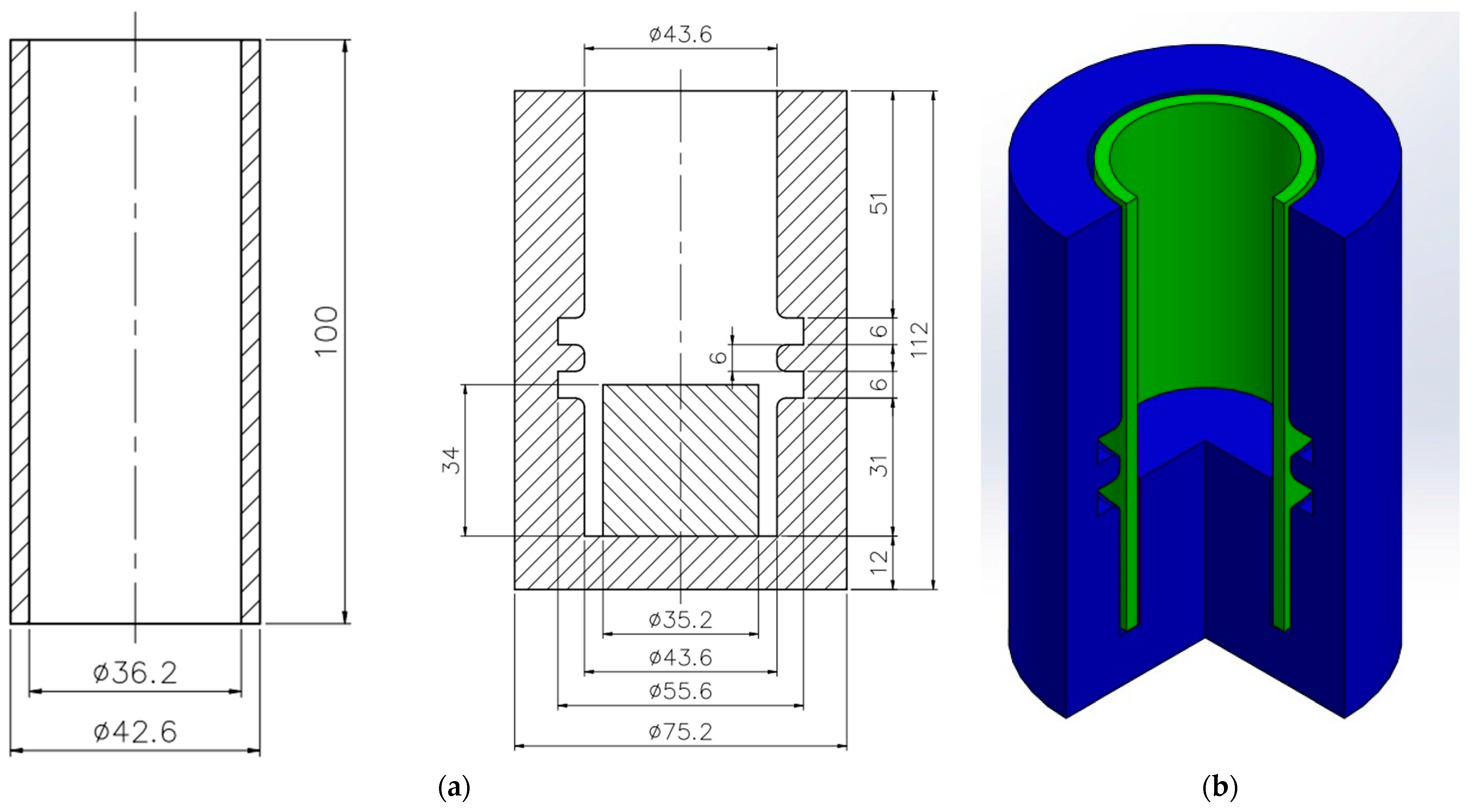
Figure 1. Geometry of the tube-die assembly: (a) the drawing of the die and the tube to the numerical study, (b) the initial geometry and the assembly of the die and tube before deformation.
Applsci 14 11126 g001
Figure 3. Boundary condition: applied loads, axis of symmetry, and fixation.
Applsci 14 11126 g003
Figure 4. Numerical model of the tube-die, ½ expansion 2D asymmetry.
Applsci 14 11126 g004
Figure 5. Mesh and von Mises stress of the tube after deformation. Mesh size: (a) 2.0 mm, (b) 1.5 mm, (c) 1.0 mm.
Applsci 14 11126 g005
Figure 6. Results of the developed tube: (a) von Mises stress, MPa; (b) X displacements, mm.
Applsci 14 11126 g006
Figure 7. Results after tube deformation: (a) von Mises stress, MPa; (b) X displacements, mm.
Applsci 14 11126 g007
Figure 8. Axisymmetric assembly tube-die: (a) ½ expansion, (b) ¾ expansion.
Applsci 14 11126 g008
Figure 9. Tests in a wrinkled tube in different materials in top and front view.
Applsci 14 11126 g009
Table 1. Displacements in the X and Y axes after tube deformation.
Displacement in XDisplacement in Y
X-axis, Upper cavity node 11,238: +2.937 mmY-axis, Upper cavity node 11,592: −1.2645 mm
X-axis, Lower cavity node 11,215: +3.2797 mm
Maximum pressure applied: 301.02 N/mm2
Table 2. Displacements in the X and Y axes after tube deformation; cavity with reduced depth.
Displacement in XDisplacement in Y
X-axis, Upper cavity node 11,177: +2.8590 mmY-axis, Upper cavity node 11,036: −1.1929 mm
X-axis, Lower cavity node 11,151: +2.848 mm
Maximum Pressure Applied: 373.478 N/mm2
Disclaimer/Publisher’s Note: The statements, opinions and data contained in all publications are solely those of the individual author(s) and contributor(s) and not of MDPI and/or the editor(s). MDPI and/or the editor(s) disclaim responsibility for any injury to people or property resulting from any ideas, methods, instructions or products referred to in the content.