Article

Individualized, 3D Printed Matrices for the Reconstruction of Severely Destructed Teeth with Subgingival Margin—Case Series and Proof of Concept

1
Department of Periodontology, Faculty of Dentistry, University of Szeged, Tisza Lajos Street 64-66, 6720 Szeged, Hungary
2
Doctoral School of Clinical Medicine, Albert Szent-Györgyi Medical School, University of Szeged, Korányi Fasor 6, 6720 Szeged, Hungary
3
Department of Operative and Esthetic Dentistry, Faculty of Dentistry, University of Szeged, Tisza Lajos Street 64-66, 6720 Szeged, Hungary
4
dicomLAB Dental Ltd., Szent-Györgyi Albert Street 2, 6726 Szeged, Hungary
5
Department of Periodontology, Semmelweis University, Szentkirályi Street 47, 1088 Budapest, Hungary
*
Author to whom correspondence should be addressed.
These authors contributed equally to this work.
Appl. Sci. 2024, 14(23), 10792; https://doi.org/10.3390/app142310792
Submission received: 17 September 2024 / Revised: 17 October 2024 / Accepted: 19 November 2024 / Published: 21 November 2024
(This article belongs to the Special Issue State-of-the-Art Operative Dentistry)

Abstract

:
Restoring deep, extensive carious lesions and subgingival situations can be challenging due to difficulties in placing matrices and achieving isolation. This article describes a technique utilizing individually designed digital matrices for challenging cases, offering an alternative solution aiding the reconstruction of the missing dental structures. Three cases are presented with difficult subgingival cavities or severe destruction of dental hard tissues, where a custom-made matrix was used to bridge the challenges of matrix placement and isolation. Digital impressions of dental arches were taken, and custom-made metal instruments were manufactured through computer-aided design and subsequent sintering. These instruments aided the elevation of deep margins and the reconstruction of the teeth. The presented technique yielded favorable results in terms of accuracy and feasibility for these challenging cases. However, it should be noted that the procedure requires additional time and incurs costs for the necessary elements.

1. Introduction

In daily practice, performing direct adhesive restorations in the posterior region is one of the most frequent dental procedures [1,2,3]. It is well known that when adhesive restorations are planned, the working area has to be properly isolated and a strict protocol has to be followed for the successful usage of these restorative materials. Today, utilizing rubber dam isolation is highly recommended when treating posterior teeth adhesively [4,5]. As stated by Heintze et al., the lifespan of resin-based composites is longer when rubber dam isolations are used [6] as it keeps away moisture (saliva, sulcus fluid, blood) from the working field, which this way will not compromise the adhesion to dentin [7,8]. Proper isolation of these teeth is essential, especially in cases of subgingival, extensive cavities or hard tissue deficiencies. In order to safely treat such situations, in 1998 Dietschi and Spreafico introduced a technique named “cervical margin relocation” (CMR) [9], which was renamed to “deep margin elevation” (DME) in 2012 by Spreafico and Magne [10]. DME is indicated when the isolation of the gingival margin of a Class II interproximal cavity is not straightforward by applying the rubber dam alone as an alternative to performing surgical gum recontouring (gingivectomy) to expose the covered gingival margin [11]. In these cases, a base of direct resin composite is placed by using a metal interproximal matrix to elevate the existing gingival part, which will later serve as a foundation for the future indirect bonded restoration. As a result of this, the previously subgingivally located margin can be predictably captured by a conventional impression and/or intraoral optical scanning (IOS) [10].
However, the application of rubber dam isolation can be extremely complicated in DME cases for several reasons: (i) the presence of deep carious lesions located subgingivally that interfere with the rubber dam clamp, (ii) difficulties in applying the matrix system and rubber dam on the same tooth, (iii) interference between the clamp and the matrix, (iv) irregular gum line making rubber dam inversion impossible, etc. [12]. Not only can the placement of the rubber dam be problematic but also the selection and application of the appropriate matrix can pose challenges. These situations often require chairside modified matrices (e.g., a greater curve or “banana-shaped” matrix) [10] or chairside tailoring of conventional matrices (e.g., the “matrix-in-a-matrix” technique) [13], making these cases highly dependent on the operator’s skills. Furthermore, proper adaptation of these modified solutions is often challenging and time-consuming, whereas adaptation is of key importance to reach success in these delicate cases.
Due to the above-mentioned difficulties, many articles indicate the surgical modification (gingivectomy) of the involved gum area [14,15,16]. However, such surgery is often demanding both from the operator’s and the patient’s side [16]. Whenever biologically possible (without violation of the biological width), the aim would be to solve these situations with proper matrices without correction of the gum. The ideal matrix must provide not only proper sealing at the gingival margin but also an ideal emergence profile to the new restorative margin to facilitate the establishment of the contact point with the future final restoration. As shown by Bresser et al., a proper contact point establishment increases the success of indirect restorations with previous DME [17].
The often irregular shape of the interproximal cavity margin before DME can benefit from using an individualized matrix to assist in the DME and the core build-up process. Over the past decade, digital innovation has played a significant role in the advancement of dentistry [18]. The ongoing developments in additive manufacturing (3D printing) and IOS have enabled the design and production of highly accurate dentures [19]. Digital impressions offer a faster and more comfortable alternative to conventional impressions and allow for the creation of realistic clinical situations in a 3D model [20]. Utilizing virtual models acquired by IOS, various appliances can be designed and fabricated using different additive manufacturing technologies, such as the selective laser sintering (SLS) of metals, the lithography-based ceramic manufacturing (LCM) of zirconia, or the manufacturing of plastics using stereolithography (SLA) [21].
The current case report aimed to present a digital approach for the treatment of deep interproximal carious defects or severely destructed cases using individualized, anatomical matrix systems acquired by computer-aided design (CAD) and computer-added manufacturing (CAM).

2. Case Presentation

Three patients were included in the present case report. All patients were treated in the lower lateral region and were in good general health. None of the patients had any contra-indications to the restorative treatment. Restorative procedures were performed with the understanding and written informed consent of all patients. The clinical procedures were carried out in accordance with the Declaration of Helsinki, as revised in 2013 [22]. The present case reports followed the CARE guidelines [23] and the CARE checklist is provided as a Supplementary File (Supplementary File S1_CAREchecklist).

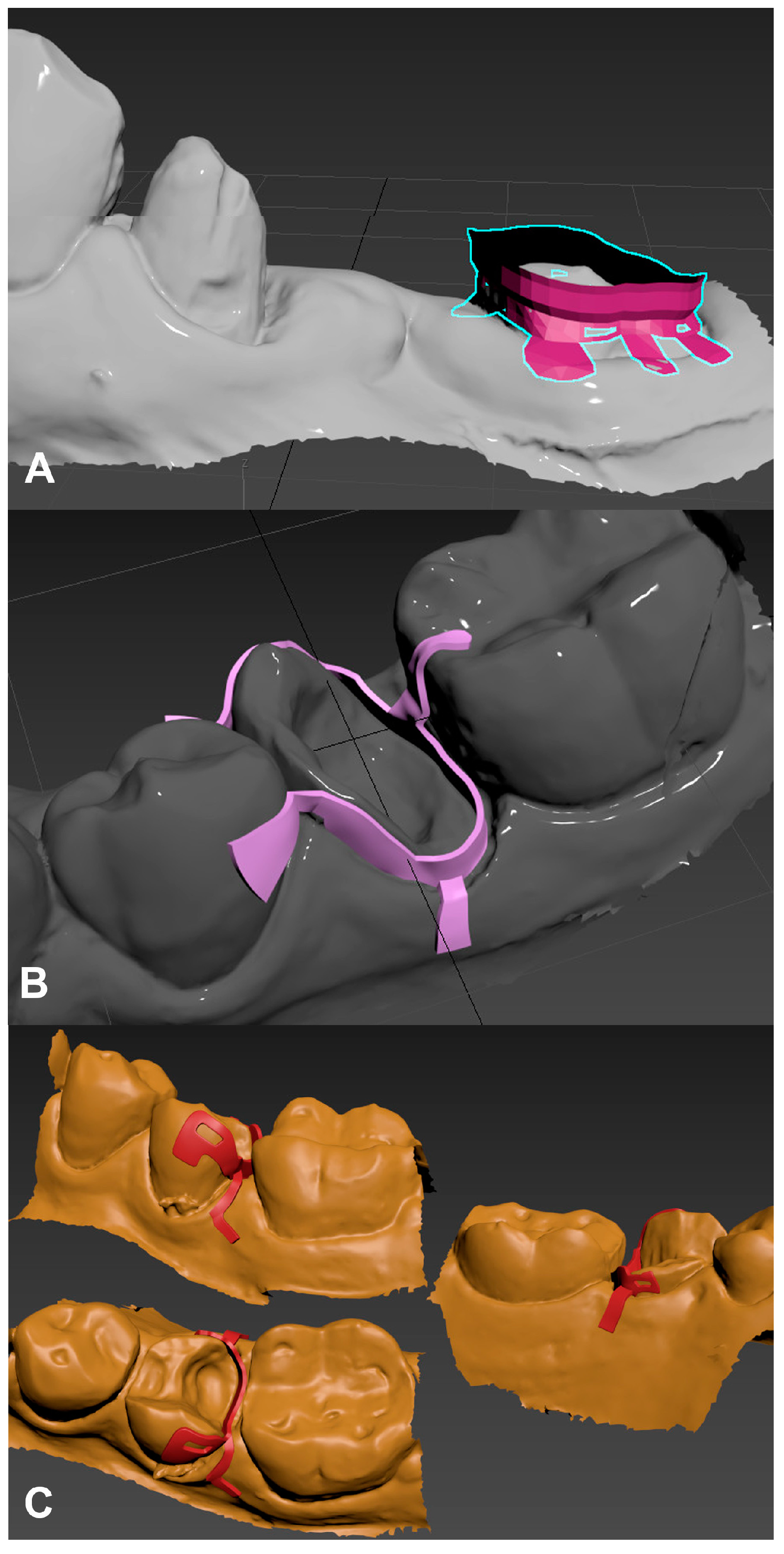
2.1. Design and Manufacturing of the Custom Matrices

2.1.1. D Modeling

The custom matrix was manufactured using digital modeling and metal SLS 3D printing. Digital impressions of the treated teeth were taken with IOS (TRIOS, 3Shape A/S, Coppenhagen, Denmark) (Figure 1) to acquire a virtual model of the residual tooth structure and morphology.
The intraoral digital impressions were exported as standard tessellation language (STL) files and were imported into an open-source 3D modeling program (Blender 3.5, Blender Foundation). The authors would like to highlight that any other software (e.g., Autodesk Maya, 3DStudio MAX 2020.1, etc.) capable of polygonal modeling can be utilized for creating the model. The custom matrix was designed and modeled on the surface of the digital impression, which is equivalent to the clinical situation (Figure 2). The authors would like to emphasize that it is important to generate an offset of 0.1 mm-s between the matrix and the tooth surface; otherwise, the fit of the matrix will be too tight and cannot be properly positioned. Fenestrations were made in certain parts of the matrix to allow it to be attached to the teeth in different areas. Wings were designed to ensure that the rubber dam is held firmly with a slight apical pressure. Depending on the specific case, wings can be positioned on the gingiva or neighboring teeth. It should be noted that the different parts of the matrix cannot be manufactured below 0.2 mm thickness due to the limitations of the SLS technology and the risk of fracture of the matrix. The custom matrix was 0.4 mm thick in all three presented cases. However, it is important to note that in these cases it is advisable to keep the thickness as close to the minimum as possible. The reason for this is that the matrix must be flexible with minimal bending to allow proper positioning.

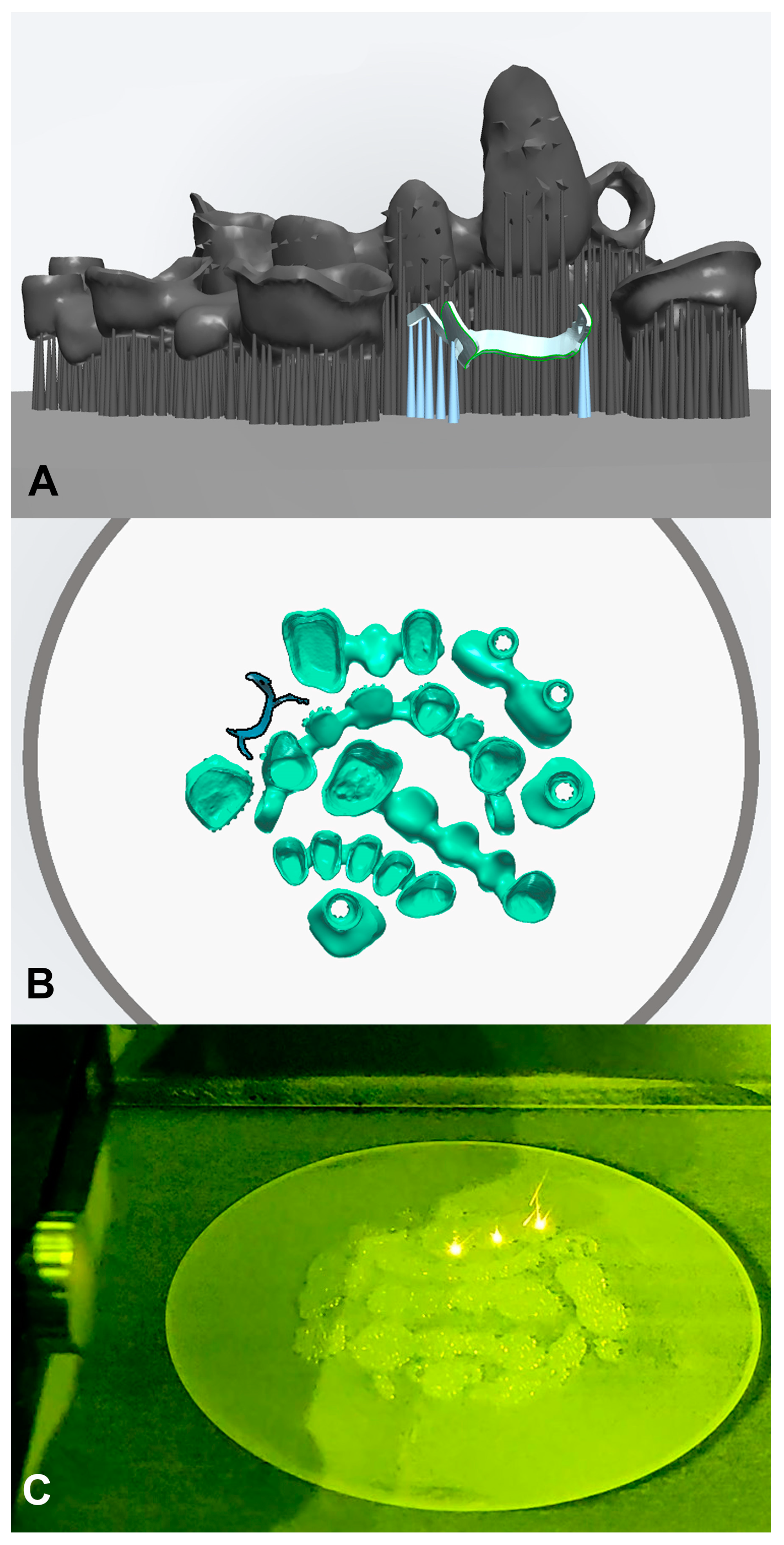
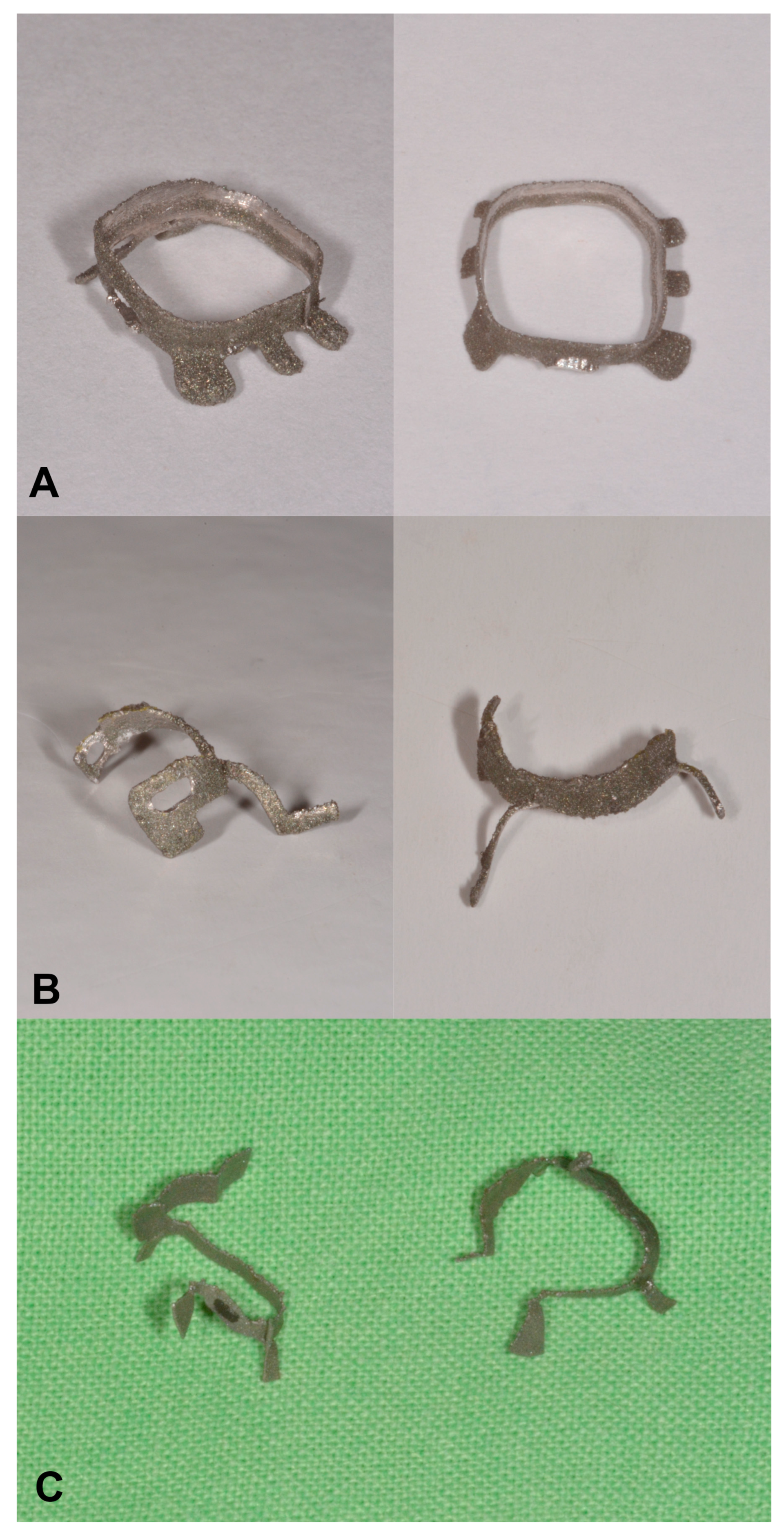
2.1.2. Additive Manufacturing

The completed model of the matrix was saved in STL format and sent to the dental laboratory (AB DENT DESIGN, Domaszék, Hungary), where it was fabricated with an SLS 3D printer (MYSINT, 300 SISMA, Vicenza, Italy) using a cobalt-based metal powder (Mediloy S-Co, BEGO, Bremen, Germany). During SLS manufacturing a high-power laser selectively sinters the powdered metal particles together, layer by layer, to create the three-dimensional object (Figure 3).
During the manufacturing process, the density of the material is close to 100%, resulting in the highest tensile strength value. After manufacturing, the surface of the matrix remains rough, which must be polished or sandblasted afterward. To simultaneously maintain structural rigidity and flexibility, the surface of the device was only smoothed on the inside, but only to an extent that did not affect the accuracy (Figure 4).

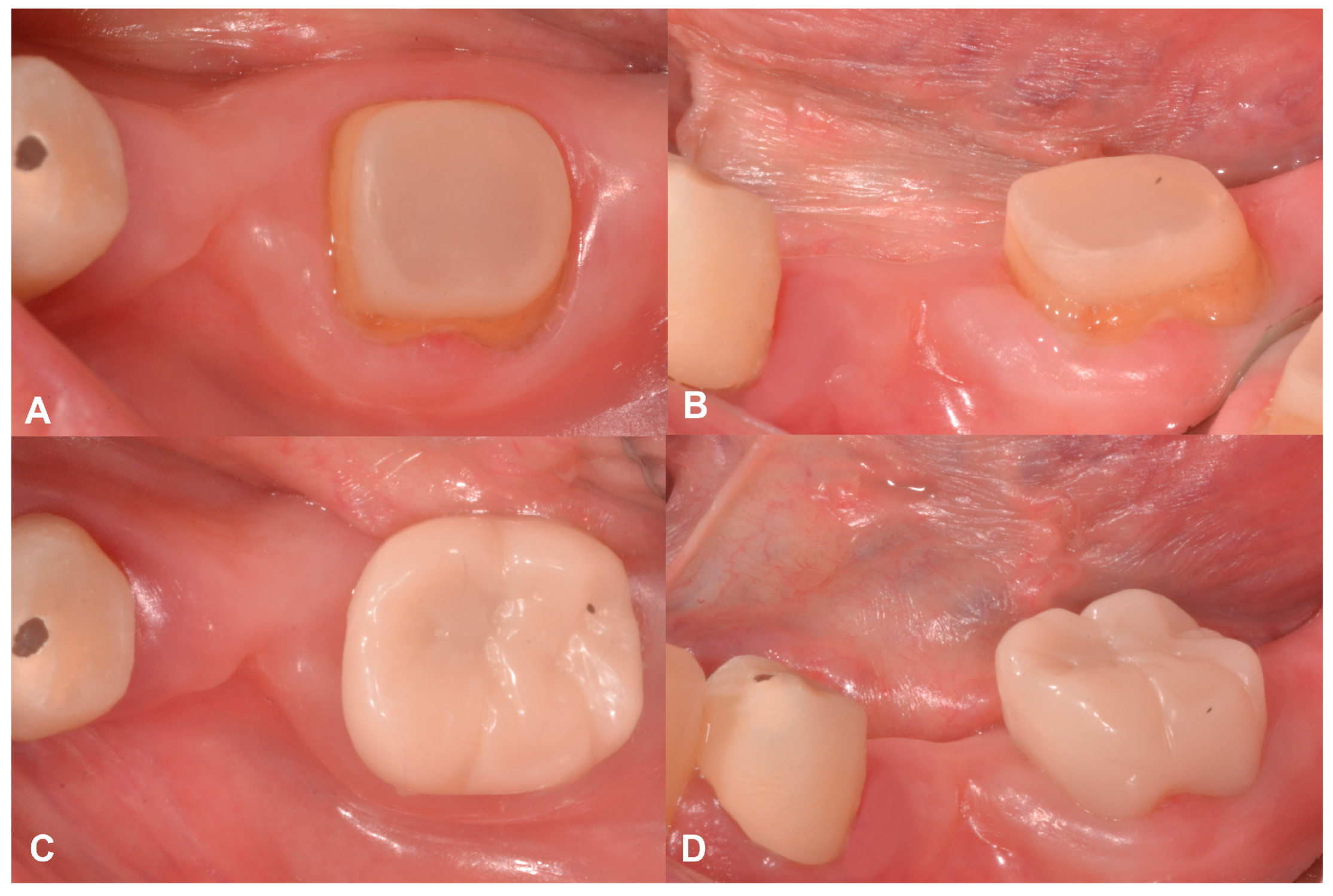
2.2. Case Presentation #1

2.2.1. Anamnesis, Physical Examination

A 68-year-old female patient sought emergency treatment at our clinic due to complaints related to her lower left first molar (36). She reported experiencing pain while chewing and occasional spontaneous discomfort. Upon clinical examination, the patient presented with swelling and discharge adjacent to the affected molar tooth. It is important to note that the tooth in question (tooth 36) serves as the distal abutment of a three-unit bridge that replaced the second premolar (Figure 5A,B).
The patient’s medical history was non-contributory to dental care. No asymmetries, painful areas in the head and neck, or swelling could be observed during extraoral examination. Intraoral examination revealed a narrow, 10 mm deep pocket on the buccal surface of this molar as a consequence of an endo-perio lesion. Normal probing depth could be registered at all other sites around this tooth. The soft tissue was inflamed, and bleeding appeared on gentle periodontal probing. The patient was informed about the treatment options and decided to have the bridge removed. Before removing the bridge, a silicon impression was taken for future temporary restoration.

2.2.2. Treatment

After local anesthesia, the three-unit bridge with the abutment teeth 34 and 36 was removed (Figure 5C). An extensive carious lesion was revealed on the coronal part of the molar tooth. Following caries removal, the pulp chamber was exposed. Due to the limited amount of remaining sound tooth structure, a pre-endodontic build-up was necessary. However, achieving stable rubber dam isolation posed challenges as the preparation margin was located subgingivally. Thus, the initial treatment only aimed to alleviate the patient’s acute pain. An access cavity was created, and root canal treatment was performed (Figure 5D). Calcium hydroxide paste was placed into the root canals, and the access cavity was temporarily filled with Cavit W. (3M, St. Paul, MN, USA). After the first appointment, the patient was relieved from the pain. The custom matrix was designed after the first visit.
At the second appointment after test fitting, the matrix was placed in the ideal position and was fixed to the remaining tooth structure by applying an adhesive system (G-premio Bond, GC Europe, Leuven, Belgium) and flowable composite (Gradia Direct Flow A2, GC Europe) through the fenestrations in the matrix. A stable fixation of the matrix was achieved on the molar, and with the help of the wings, it kept the rubber dam away and in place. This created an ideal working area for the restorative procedure. After drying the cavity, a one-step self-etch adhesive system (G-premio Bond, GC Europe) was used according to the manufacturer’s instructions. The adhesive was light-cured for 60 s. A permanent, pre-endodontic build-up was created using conventional composite material (Gradia Direct Posterior A2, GC Europe). After the build-up, the matrix was removed and the composite build-up was finished and polished. This individualized treatment made rubber dam application possible for the following endodontic procedures (Figure 6).
Afterward, the root canal treatment was continued, a control X-ray was taken and the mechanical shaping and cleaning were completed. Following root canal obturation, a core build-up was performed, and the tooth was fitted with a temporary crown (Figure 7). The patient’s overall rehabilitation goes beyond this case presentation. At the 1-year follow-up, the final restoration could be seen and the periapical region had healed (Figure 8A,B).

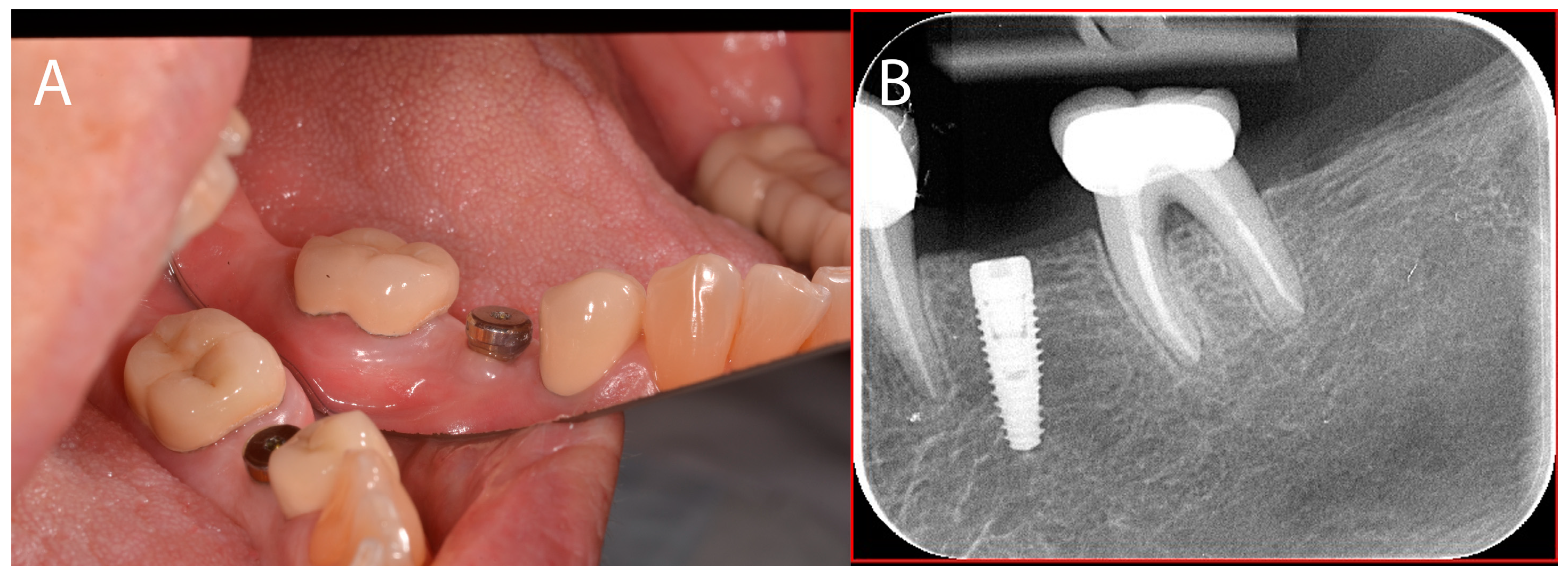
2.3. Case Presentation #2

2.3.1. Anamnesis, Physical Examination

A 30-year-old male patient was treated by undergraduate students. The restorative treatment of the lower left premolar (35) was discontinued as the students were unable to isolate and place a matrix on the tooth for a direct restoration during their dental practice (Figure 9). The tooth was asymptomatic and vital. The patient’s medical history was non-contributory to dental care. No asymmetries, painful areas in the head and neck, or swelling could be observed during extraoral examination. The special shape of the cavity indicated the usage of an individualized matrix in order to aid the restorative treatment. Also, in this case, the individualized matrix could serve as an alternative rubber dam clamp to stabilize the rubber dam simultaneously.

2.3.2. Treatment

After local anesthesia, the temporary filling was removed, and the cavity was cleaned. A size 0 retraction cord was placed in the disto-interproximal gingival sulcus. A digital impression was taken of the lower premolar and the surrounding area with an IOS (TRIOS, 3Shape A/S). On the digital impression, it could be observed that the position of the gingival margin was below the interdental papilla. Furthermore, the curved profile of the interproximal cavity margin made it difficult to apply a prefabricated matrix. These observations supported the indication for an individualized solution. The digital model was segmented between the premolars, which enabled the digital design of the matrix. The wings of the matrix were positioned in relation to soft tissues and the neighboring tooth. The model was saved as an STL file and sent to the dental lab where the matrix was manufactured.
At the next appointment, following the administration of local anesthesia, the temporary filling was removed, and the matrix was tested for fit. The inner surface of the matrix was polished to ensure a smooth composite build-up. After confirming its proper fit and seal, rubber dam isolation was applied to tooth 36, including the neighboring teeth. The rubber dam was positioned apically on the lingual and buccal sides of tooth 35, and then the customized matrix was placed and secured on the tooth using an adhesive system (G-Premio Bond, GC Europe) and flowable composite (Gradia Direct Flow A2, GC Europe). The fixation process was aided by two perforated sections of the matrix specifically designed for this purpose.
After the metal matrix was positioned and fixed, selective orthophosphoric acid conditioning on enamel was carried out. After drying the cavity, a one-step self-etch adhesive system (G-premio Bond, GC Europe) was applied following the manufacturer’s instructions. The adhesive was then light-cured for 60 s. For the build-up, conventional composite material (Gradia Direct Posterior A2, GC Europe) was utilized (Figure 10).
The coronal destruction was later restored with an indirect composite overlay (Figure 11). At the 1-year follow-up, the restoration was functioning well and the interproximal region was cleansable (Figure 12).

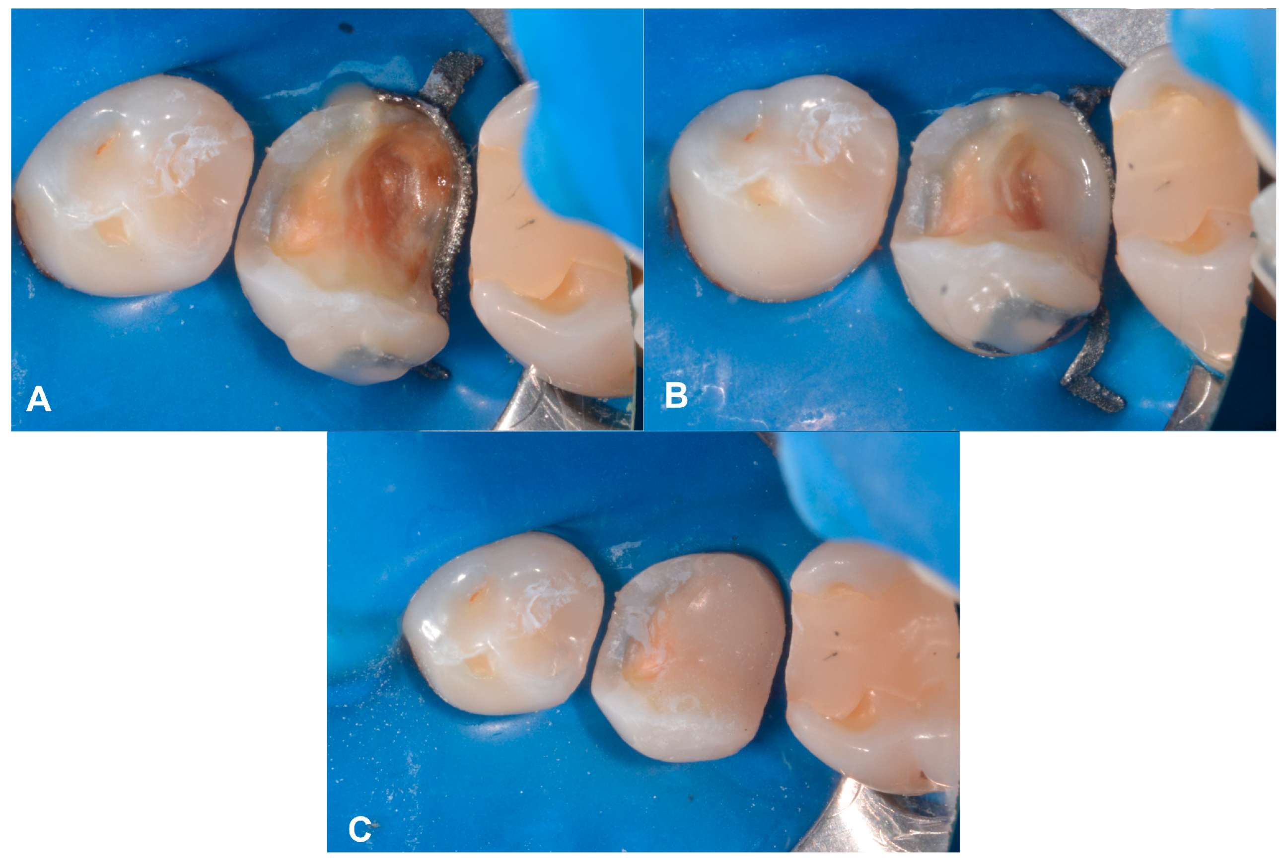
2.4. Case Presentation #3

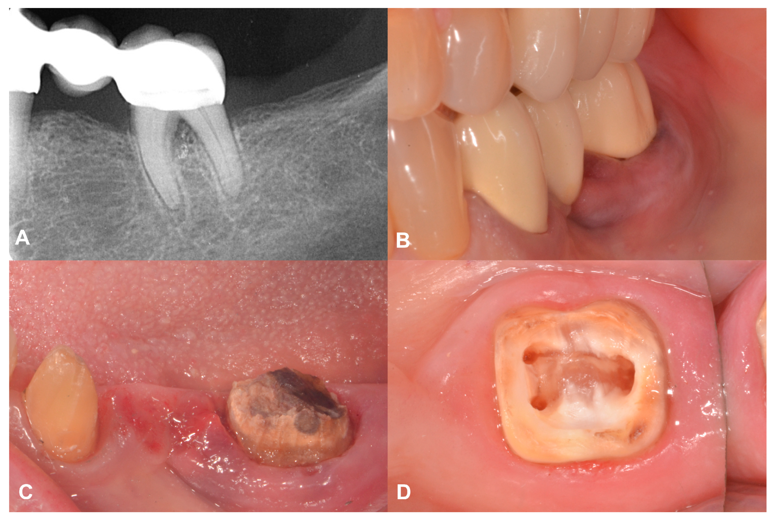
2.4.1. Anamnesis, Physical Examination
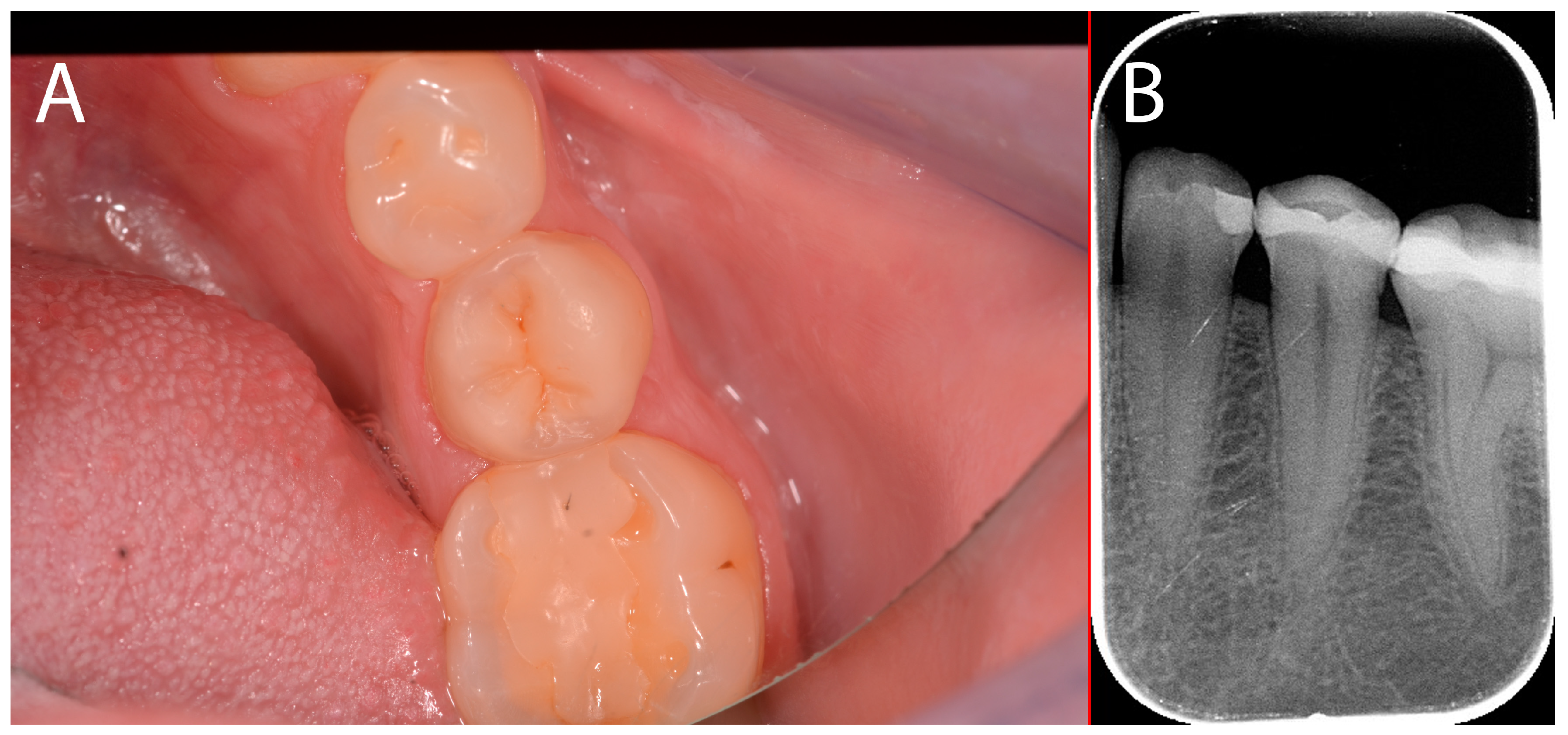
A 25-year-old female patient was referred to the dental clinic seeking treatment for tooth 35. The patient’s medical history was not relevant to dental care. No asymmetries, painful areas in the head and neck, or swelling were observed during the extraoral examination. As per the referral, the cavity’s shape and extent posed challenges in achieving proper isolation and matrix placement following the removal of the carious lesion (Figure 13).

2.4.2. Treatment

In the first session, a digital impression was taken. A gingival retraction cord was inserted on the distal surface to allow imaging of the cavity edge during intraoral scanning. After the digital impression (TRIOS, 3Shape A/S), the STL file was loaded into the digital modeling software. In the present case, two different appliances were designed to aid attachment to the adjacent teeth. The final models were sent to the dental laboratory for printing.
In the following session, after local anesthesia, the temporary filling was removed, and the field was isolated with rubber dam isolation. After positioning the custom matrix and stabilizing it with an adhesive system (G-Premio Bond, GC Europe) and flowable composite (Gradia Direct A2 Flow, GC Europe), the position of the rubber dam became satisfactory and stable around the treated tooth. Adhesive treatment and DME were performed in the same manner and with the same materials as described above in Cases 1 and 2. After cutting back the coronal part of the root canal filling with Number 3 Gates-Glidden burs (Dentsply Maillefer, Tulsa, OK, USA), a direct post and core was fabricated using the Bioblock technique with short fiber-reinforced composite (everX Flow Bulk Shade, GC Europe) as described by Fráter et al. [24,25,26] (Figure 14).
In the following session, tooth 35 was prepared for indirect restoration; impressions and bite registration were taken. Subsequently, in the final session, an indirect restoration was adhesively luted (Figure 15). At the 1-year follow-up, the restoration was functioning well and the interproximal region was cleansable; however, the orthodontic appliances were making this difficult (Figure 16).

3. Discussion

The current case report presented a novel approach by utilizing digitally designed and additively manufactured, individualized matrices for the restoration of severely destructed and/or subgingival cavities. Laser-sintered individualized matrices serve dual purposes in the current setting. Firstly, due to the individualized design, the matrices are able to follow the natural curvature of the teeth allowing for a gapless fit and a more natural emergence profile of the finalized restoration. Secondly, the wings of the individualized matrices ensure that the rubber dam is held firmly in a slight apical position, therefore an ideal working area can be created for the restorative process. Based upon the so far gathered experience, an individually designed matrix is mainly indicated for the restorative treatment of deep and extensive subgingival cavities or hard tissue destructions not invading the biological width (e.g., grade 1 and grade 2 classifications from Veneziani et al.) [15].
In any DME procedure, optimal marginal adaptation of restorative materials is crucial for preventing microleakage, ensuring longevity, and maintaining periodontal health, making it essential for clinicians to select materials like lithium disilicate, zirconia, or other advanced ceramics that provide superior adaptation to the tooth structure in order to achieve durable and biologically compatible restorations [27]. To the best of the authors’ knowledge, no similar methods can be found in the literature for aiding the DME procedure, although previously, a few articles have described a 3D-guided direct composite restoration method utilizing CAD and 3D printing [28,29,30]. However, all of these articles have utilized 3D printed guides in conjunction with direct composite veneers in the upper anterior region. With the above-proposed method, DME or core build-up can be performed in a more reproducible way under adequate isolation ideal for adhesive treatment. 3D printing has been proven to increase the reliability and reproducibility of dental interventions. In different surgical fields, stereolithography (SLA) 3D printing is utilized to manufacture surgical guides that translate the digital plan into surgical practice. Currently, 3D-printed surgical guides are most used in implant dentistry [31], bimaxillary orthognathic surgery [32], and maxillofacial oncological rehabilitation [33]. Other technologies, such as metal SLS 3D printing technology, are most commonly used to manufacture patient-specific implants and customized titanium meshes for vertical guided bone regeneration [34]. In the field of prosthetic dentistry, various 3D printing technologies have recently surfaced for the manufacturing of fixed and removable prostheses [35,36]; however, the effectiveness of 3D printing compared to subtractive manufacturing (standard of care) is still under debate. Table 1 summarizes the main differences between the use of a prefabricated traditional matrix and a customized matrix.
Despite the obvious clinical benefits of this method, there are a few shortcomings that have to be addressed and improved in the future. The 3D design process is relatively time-consuming, has a learning curve, and utilizes software that is not specifically meant for this purpose. However, there are alternative solutions. As an option, Blender is a free and open-source 3D computer graphics software tool, which is suitable for creating such matrices. Furthermore, there is a YouTube channel that discusses the direct dental application of the Blender software (Blenderfordental). It is also possible that the design of matrices, like other indirect restorations, would be designed by dental technicians using the software available to them or via Blender. The general management method of the Blender software is also available on YouTube in the form of free videos. This could aid the learning process of designing such individualized matrixes. It may also be possible to develop software that could only be used for this task, but seeing that many dentists create unique templates and tools for different interventions digitally, it may be more expedient to use the software already available. To improve the efficiency of the designing process in the future, certain steps should be automated with the application of specific software designed for this purpose. The second disadvantage of these customized matrices is that their fabrication poses an extra cost to the patient. However, this price is approximately the price of a metal cast in the case of a porcelain-fused metal crown, which can be incorporated into the average pricing in everyday clinical practice. Also, a scanner is mandatory for this procedure, which is an extra cost for the dental practice. The third disadvantage of the proposed workflow is the required time for fabrication and the subsequent delay in the treatment. First, there is the time (approx. 5–10 min) required to scan the affected area. After importing the STL file into the software (e.g., Blender), the designing process itself takes an experienced “operator” approx. 15–20 min, which is the same amount of time as creating a simple surgical implant template. After designing the template, the STL file is sent to the lab, and the physical matrix is usually prepared with several other restorations, which takes about approx. 6–8 h. Therefore, once the cavity is finalized and scanned, a temporary filling should be placed and treatment should be continued in another session once the matric has been fabricated. Last, but not least, the usage of a custom matrix requires a more experienced operator in order for the attempt to be successful since the application of the individual matrix can be difficult in cases with a large tooth substance loss. Due to its small size, thinness, and, therefore, potential distortion, it can be difficult to place the matrix in the correct position for the appropriate design. In addition, holding the matrix in the intended position requires composite fixation to the tooth, which can also be complicated by the elasticity of the rubber dam. In most cases, the help of an assistant is required for fitting.
As a limitation, the authors would like to state that, as the proposed method is unique and rather new, there is no long-term follow-up on such cases. In the future, there is clearly a need for extended follow-up periods to evaluate the durability of these restorations and their impact on periodontal health. Also, long-term data on the maintenance of marginal integrity, as well as potential biological complications, are essential for validating the technique’s effectiveness. Furthermore, in the future, the proposed technique should be validated in a split-mouth design, adding a traditional matrixing method (as a control) to allow a clear comparison.

4. Conclusions

The presented cases involved challenging clinical situations where restoring severely damaged teeth with adhesive restorations had become difficult. The difficulty arose due to factors such as severe destruction, parts that were difficult to isolate, and irregular subgingival cavity margins. In our daily practice, we frequently encounter similar situations, necessitating the exploration of new, preferably individualized techniques. The custom matrices demonstrated stability, provided satisfactory isolation, and facilitated the creation of an ideal DME profile and subsequent core build-up. While this new approach may be time-consuming, the results are promising as they provide a straightforward solution for each unique case. Therefore, we suggest that when applied in the appropriate indications, this new approach can contribute to the successful resolution of challenging cases in everyday clinical practice.

Supplementary Materials

The following supporting information can be downloaded at: https://www.mdpi.com/article/10.3390/app142310792/s1, Supplementary File S1: CARE Checklist.

Author Contributions

Conceptualization: B.S.; Methodology: B.S., V.N., A.J. and M.F.; Data curation: B.S. and V.N.; Investigation: B.S. and M.F.; Project administration: A.J.; Writing—original draft: B.S.; Writing—review and editing: G.B., D.P. and M.F.; Supervision and resources: M.F. All authors have read and agreed to the published version of the manuscript.

Funding

This work was supported by the Bolyai János Research Grant (BO/00283/24/5).

Institutional Review Board Statement

The study protocol was conducted in full accordance with the Declaration of Helsinki of 1975, revised in 2013. Ethical approval was obtained from the Regional and Institutional Review Board of Human Investigations at the University of Szeged (protocol number 2024/1). Interventions were performed with the understanding of the patients, and informed consent was signed by every participant.

Informed Consent Statement

Informed consent was obtained from all subjects involved in the study. All the participants signed written informed consent for the publication of identifying information or images in an online open-access publication.

Data Availability Statement

The datasets used and/or analyzed during this study are available from the corresponding author upon reasonable request.

Conflicts of Interest

Author G.B. was employed by the company dicomLAB Dental Ltd. (Szeged, Hungary). The remaining authors declare that the research was conducted in the absence of any commercial or financial relationships that could be construed as a potential conflict of interest.

References

  1. Haak, R.; Näke, T.; Park, K.-J.; Ziebolz, D.; Krause, F.; Schneider, H. Internal and Marginal Adaptation of High-Viscosity Bulk-Fill Composites in Class II Cavities Placed with Different Adhesive Strategies. Odontology 2019, 107, 374–382. [Google Scholar] [CrossRef] [PubMed]
  2. Demarco, F.F.; Corrêa, M.B.; Cenci, M.S.; Moraes, R.R.; Opdam, N.J.M. Longevity of Posterior Composite Restorations: Not Only a Matter of Materials. Dent. Mater. 2012, 28, 87–101. [Google Scholar] [CrossRef]
  3. Opdam, N.J.M.; Van De Sande, F.H.; Bronkhorst, E.; Cenci, M.S.; Bottenberg, P.; Pallesen, U.; Gaengler, P.; Lindberg, A.; Huysmans, M.C.D.N.J.M.; Van Dijken, J.W. Longevity of Posterior Composite Restorations: A Systematic Review and Meta-Analysis. J. Dent. Res. 2014, 93, 943–949. [Google Scholar] [CrossRef] [PubMed]
  4. Peumans, M.; Politano, G.; Van Meerbeek, B. Effective Protocol for Daily High-Quality Direct Posterior Composite Restorations. Cavity Preparation and Design. J. Adhes. Dent. 2020, 22, 581–596. [Google Scholar] [CrossRef]
  5. Peumans, M.; Venuti, P.; Politano, G.; Van Meerbeek, B. Effective Protocol for Daily High-Quality Direct Posterior Composite Restorations. The Interdental Anatomy of the Class-2 Composite Restoration. J. Adhes. Dent. 2021, 23, 21–34. [Google Scholar] [CrossRef] [PubMed]
  6. Heintze, S.D.; Rousson, V. Clinical Effectiveness of Direct Class II Restorations—A Meta-Analysis. J. Adhes. Dent. 2012, 14, 407–431. [Google Scholar] [CrossRef] [PubMed]
  7. Koppolu, M.; Gogala, D.; Mathew, V.; Thangala, V.; Deepthi, M.; Sasidhar, N. Effect of Saliva and Blood Contamination on the Bond Strength of Self-Etching Adhesive System- An in Vitro Study. J. Conserv. Dent. 2012, 15, 270. [Google Scholar] [CrossRef] [PubMed]
  8. Duarte, S.J.; Lolato, A.L.; de Freitas, C.R.B.; Dinelli, W. SEM Analysis of Internal Adaptation of Adhesive Restorations after Contamination with Saliva. J. Adhes. Dent. 2005, 7, 51–56. [Google Scholar]
  9. Dietschi, D.; Spreafico, R. Current Clinical Concepts for Adhesive Cementation of Tooth-Colored Posterior Restorations. Pract. Periodontics Aesthet. Dent. 1998, 10, 47–54, quiz 56. [Google Scholar]
  10. Magne, P.; Spreafico, R. Deep Margin Elevation: A Paradigm Shift. Am. J. Esthet. Dent. 2012, 2, 86–96. [Google Scholar]
  11. Ferrari, M.; Koken, S.; Grandini, S.; Ferrari Cagidiaco, E.; Joda, T.; Discepoli, N. Influence of Cervical Margin Relocation (CMR) on Periodontal Health: 12-Month Results of a Controlled Trial. J. Dent. 2018, 69, 70–76. [Google Scholar] [CrossRef] [PubMed]
  12. Kielbassa, A.M.; Philipp, F. Restoring Proximal Cavities of Molars Using the Proximal Box Elevation Technique: Systematic Review and Report of a Case. Quintessence Int. 2015, 46, 751–764. [Google Scholar] [CrossRef] [PubMed]
  13. Magne, P. M-i-M for DME: Matrix-in-a-Matrix Technique for Deep Margin Elevation. J. Prosthet. Dent. 2023, 130, 434–438. [Google Scholar] [CrossRef] [PubMed]
  14. Ghezzi, C.; Brambilla, G.; Conti, A.; Dosoli, R.; Ceroni, F.; Ferrantino, L. Cervical Margin Relocation: Case Series and New Classification System. Int. J. Esthet. Dent. 2019, 14, 272–284. [Google Scholar]
  15. Veneziani, M. Adhesive Restorations in the Posterior Area with Subgingival Cervical Margins: New Classification and Differentiated Treatment Approach. Eur. J. Esthet. Dent. 2010, 5, 50–76. [Google Scholar]
  16. Romano, G.; Modoni, M.; Ferraris, F.; Zakaraya, A.; Rasperini, G. Supracrestal Tissue Esthetic Management (STEM) Technique and Current Approaches in Restorative and Surgical Treatment of Deep Margins. Int. J. Esthet. Dent. 2022, 17, 162–184. [Google Scholar]
  17. Bresser, R.A.; Gerdolle, D.; Van Den Heijkant, I.A.; Sluiter-Pouwels, L.M.A.; Cune, M.S.; Gresnigt, M.M.M. Up to 12 Years Clinical Evaluation of 197 Partial Indirect Restorations with Deep Margin Elevation in the Posterior Region. J. Dent. 2019, 91, 103227. [Google Scholar] [CrossRef]
  18. Kihara, H.; Hatakeyama, W.; Komine, F.; Takafuji, K.; Takahashi, T.; Yokota, J.; Oriso, K.; Kondo, H. Accuracy and Practicality of Intraoral Scanner in Dentistry: A Literature Review. J. Prosthodont. Res. 2020, 64, 109–113. [Google Scholar] [CrossRef] [PubMed]
  19. Laverty, D.P.; Thomas, M.B.; Clark, P.; Addy, L.D. The Use of 3D Metal Printing (Direct Metal Laser Sintering) in Removable Prosthodontics. Dent. Update 2016, 43, 826–835. [Google Scholar] [CrossRef]
  20. Mangano, F.; Gandolfi, A.; Luongo, G.; Logozzo, S. Intraoral Scanners in Dentistry: A Review of the Current Literature. BMC Oral Health 2017, 17, 149. [Google Scholar] [CrossRef]
  21. Kessler, A.; Hickel, R.; Reymus, M. 3D Printing in Dentistry—State of the Art. Oper. Dent. 2020, 45, 30–40. [Google Scholar] [CrossRef] [PubMed]
  22. Emanuel, E.J. Reconsidering the Declaration of Helsinki. Lancet 2013, 381, 1532–1533. [Google Scholar] [CrossRef] [PubMed]
  23. Riley, D.S.; Barber, M.S.; Kienle, G.S.; Aronson, J.K.; Von Schoen-Angerer, T.; Tugwell, P.; Kiene, H.; Helfand, M.; Altman, D.G.; Sox, H.; et al. CARE Guidelines for Case Reports: Explanation and Elaboration Document. J. Clin. Epidemiol. 2017, 89, 218–235. [Google Scholar] [CrossRef] [PubMed]
  24. Fráter, M.; Sáry, T.; Braunitzer, G.; Balázs Szabó, P.; Lassila, L.; Vallittu, P.K.; Garoushi, S. Fatigue Failure of Anterior Teeth without Ferrule Restored with Individualized Fiber-Reinforced Post-Core Foundations. J. Mech. Behav. Biomed. Mater. 2021, 118, 104440. [Google Scholar] [CrossRef]
  25. Fráter, M.; Sáry, T.; Néma, V.; Braunitzer, G.; Vallittu, P.; Lassila, L.; Garoushi, S. Fatigue Failure Load of Immature Anterior Teeth: Influence of Different Fiber Post-Core Systems. Odontology 2021, 109, 222–230. [Google Scholar] [CrossRef]
  26. Fráter, M.; Lassila, L.; Braunitzer, G.; Vallittu, P.K.; Garoushi, S. Fracture Resistance and Marginal Gap Formation of Post-Core Restorations: Influence of Different Fiber-Reinforced Composites. Clin. Oral Investig. 2020, 24, 265–276. [Google Scholar] [CrossRef] [PubMed]
  27. Ferrini, F.; Paolone, G.; Di Domenico, G.L.; Pagani, N.; Gherlone, E.F. SEM Evaluation of the Marginal Accuracy of Zirconia, Lithium Disilicate, and Composite Single Crowns Created by CAD/CAM Method: Comparative Analysis of Different Materials. Materials 2023, 16, 2413. [Google Scholar] [CrossRef]
  28. Mattei, M.; Mattei, L.D. 3D-Guided Direct Composite Restorations: The Evolution of the Technique. Int. J. Esthet. Dent. 2022, 17, 266–279. [Google Scholar]
  29. Sampaio, C.S.; Puppin-Rontani, J.; Tonolli, G.; Atria, P.J. Workflow of Digitally Guided Direct Composite Resin Restorations Using Open Source Software and 3D Printing: A Clinical Technique. Quintessence Int. 2021, 52, 104–110. [Google Scholar] [CrossRef]
  30. Zhang, Y.; Zhang, J.; Fan, L.; Yu, H. Closing Post-Orthodontic Spaces between Anterior Teeth Using Sequential 3D-Printed Direct Composite Injection Guides. Oper. Dent. 2022, 47, 612–619. [Google Scholar] [CrossRef]
  31. D’haese, R.; Vrombaut, T.; Hommez, G.; De Bruyn, H.; Vandeweghe, S. Accuracy of Guided Implant Surgery Using an Intraoral Scanner and Desktop 3D-Printed Tooth-Supported Guides. Int. J. Oral Maxillofac. Implant. 2022, 37, 479–484. [Google Scholar] [CrossRef] [PubMed]
  32. Schneider, D.; Kämmerer, P.W.; Hennig, M.; Schön, G.; Thiem, D.G.E.; Bschorer, R. Customized Virtual Surgical Planning in Bimaxillary Orthognathic Surgery: A Prospective Randomized Trial. Clin. Oral Investig. 2019, 23, 3115–3122. [Google Scholar] [CrossRef] [PubMed]
  33. Gupta, S.; Goil, P. Formulating an Easy, Affordable, and Reproducible Method for Virtual Planning and 3D Reconstruction: A State Institution’s Approach for Mandibular Reconstruction. Ann. Plast. Surg. 2021, 87, 65–72. [Google Scholar] [CrossRef] [PubMed]
  34. Cucchi, A.; Vignudelli, E.; Franceschi, D.; Randellini, E.; Lizio, G.; Fiorino, A.; Corinaldesi, G. Vertical and Horizontal Ridge Augmentation Using Customized CAD/CAM Titanium Mesh with versus without Resorbable Membranes. A Randomized Clinical Trial. Clin. Oral Implant. Res. 2021, 32, 1411–1424. [Google Scholar] [CrossRef] [PubMed]
  35. De Souza, F.A.; Blois, M.C.; Collares, K.; Dos Santos, M.B.F. 3D-Printed and Conventional Provisional Single Crown Fabrication on Anterior Implants: A Randomized Clinical Trial. Dent. Mater. 2024, 40, 340–347. [Google Scholar] [CrossRef]
  36. Sun, Y.; Ding, Q.; Yuan, F.; Zhang, L.; Sun, Y.; Xie, Q. Accuracy of a Chairside, Fused Deposition Modeling Three-dimensional-printed, Single Tooth Surgical Guide for Implant Placement: A Randomized Controlled Clinical Trial. Clin. Oral Implant. Res. 2022, 33, 1000–1009. [Google Scholar] [CrossRef]
Figure 1. Virtual model of the residual tooth structure and morphology in all three cases ((AC), respectively).
Applsci 14 10792 g001
Figure 2. The custom matrix was designed and modeled on the surface of the digital impression in all three cases ((AC), respectively).
Applsci 14 10792 g002
Figure 3. (A) the 3D model of the individualized matrix in the .STL model; (B) the models are loaded in the SLS manufacturing software; (C) A high-power laser selectively sinters the powdered metal particles together, layer by layer, to create the three-dimensional object.
Applsci 14 10792 g003
Figure 4. Individualized matrices after fabrication for all three cases ((AC), respectively). After manufacturing, the surface of the object remains rough. The surface of the inside was smoothed but only to an extent that did not affect the accuracy.
Applsci 14 10792 g004
Figure 5. (A) pre-operative radiograph; (B) initial situation; (C) clinical situation after the removal of the three-unit bridge; (D) access cavity for the root canal treatment.
Applsci 14 10792 g005
Figure 6. The individualized matrix made the rubber dam isolation possible. (A) rubber dam isolation with the individualized matrix in place; (B) deep margin elevation on each side; (C) endodontic access cavity after the elevation of the margins; (D) rubber dam isolation for root canal treatment.
Applsci 14 10792 g006
Figure 7. Core build-up and temporary crown were fitted after the root canal treatment. (A) core-build up from occlusal view; (B) core build-up side view; (C) temporary crown occlusal view; (D) temporary crown side view.
Applsci 14 10792 g007
Figure 8. 1-year follow up. (A) the final restoration; (B) periapical X-ray.
Applsci 14 10792 g008
Figure 9. Initial situation: deep subgingival margin on the distal side of the lower left second premolar with (A) and without (B) temporary restoration.
Applsci 14 10792 g009
Figure 10. Deep margin elevation and core build-up with a conventional composite material. (A) rubber dam isolation with the individualized matrix in place; (B) deep margin elevation on the disto-lingual side; (C) composite core build-up.
Applsci 14 10792 g010
Figure 11. Indirect composite overlay as the final restoration.
Applsci 14 10792 g011
Figure 12. (A) intraoral situation at the 1-year follow-up; (B) periapical X-ray at the 1-year follow-up.
Applsci 14 10792 g012
Figure 13. Initial situation. (A) lateral view; (B) occlusal view.
Applsci 14 10792 g013
Figure 14. (A) placement of the fabricated matrix (occlusal view); (B,C) placement of the fabricated matrix (side view); (D) deep margin elevation on the distal side; (E) preparation of the coronal part of the root canal space; (F) creating a direct post and core build-up with short fiber-reinforced composite material.
Applsci 14 10792 g014
Figure 15. The final restoration was luted adhesively.
Applsci 14 10792 g015
Figure 16. Situation at the 1-year follow-up. (A) occlusal view of the final restoration; (B) periapical X-ray.
Applsci 14 10792 g016
Table 1. Comparison between the use of a prefabricated matrix and a customized matrix.
Traditional Prefabricated MatricesComparisonCustomized Matrices
Prefabricated matrices do not follow the cavity margin and in many cases, it is necessary to improve their fit with wedges and rings.FittingCustomized matrices follow the cavity margin better.
Traditional matrices are stable in smaller defects, where there is enough supporting tooth material.StabilityIndividualized matrices are stable even in large defects.
Conventional matrices are hard to apply with rubber dams, especially in cases of deep approximal lesions.Rubber dam isolationCustomized matrices can significantly support the rubber dam isolation.
In many cases, traditional matrices need to be adjusted with matrix rings.Matrix rings3D-printed matrices follow the remaining tooth structure without the use of matrix rings.
Conventional matrices need to be fixed with wedges or matrix rings.FixationCustomized matrices need to be fixed with composite materials.
Traditional matrices are relatively inexpensive.CostThe use of customized matrices incurs additional costs.
Prefabricated matrices can be used in a single visit.Time managementIn order to create an individualized matrix, an additional visit is required.
Disclaimer/Publisher’s Note: The statements, opinions and data contained in all publications are solely those of the individual author(s) and contributor(s) and not of MDPI and/or the editor(s). MDPI and/or the editor(s) disclaim responsibility for any injury to people or property resulting from any ideas, methods, instructions or products referred to in the content.

