Features of the Influence of the Arrangement of Parts in the Chamber of Installation During Vacuum Arc Deposition on the Properties of Coatings

 ,
, 
 ,
,  ,
, 
Abstract
1. Introduction
- Using alloy cathodes with different ratios of elements. This method is very labor-intensive and requires significant financial costs. Suitable only for mass production when a large number of cathodes of a standard composition are used.
- Changing the arc currents of the cathodes. This method is quite effective, but allows for varying the ratio of elements in the coating only in a limited range due to the fact that at an arc current below the limit value, it is impossible to form a plasma flow, and at too high arc current values, a significant phase of microparticles is formed [1,2,3,21].
- Changing the spatial position of the sample relative to the plasma flows. This method assumes a static position of the samples during the coating deposition process. Theoretically, in this case, it is possible to vary the content of metal elements in the coating from 0 to 100%; however, given the dispersion of the plasma flow, when using two or more evaporators with cathodes of different compositions, it is impossible to obtain a “clean” coating that would not contain some amount of the second (third, etc.) element.
2. Materials and Methods
- An evaporator of the filtered cathodic vacuum arc deposition (FCVAD) system [28], allowing for the effective (up to 98%) separation of microparticles. This evaporator was used for aluminum (99.80% Al) cathodes due to the high generation of microparticles during aluminum evaporation.
3. Results
4. Conclusions
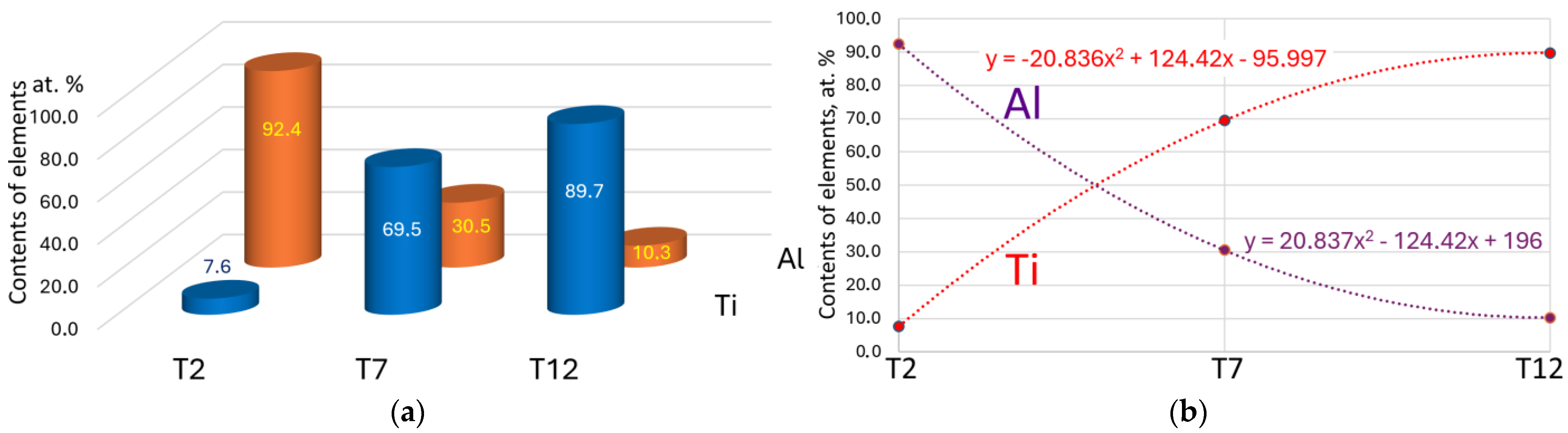
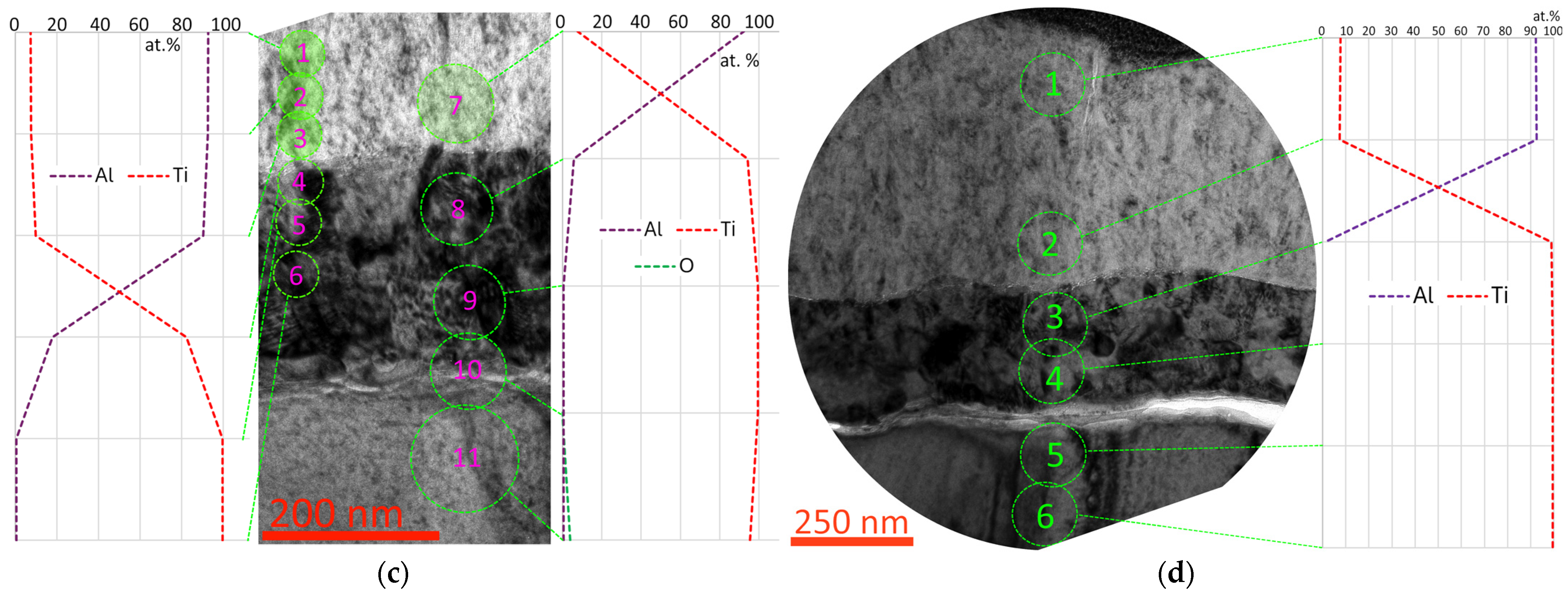
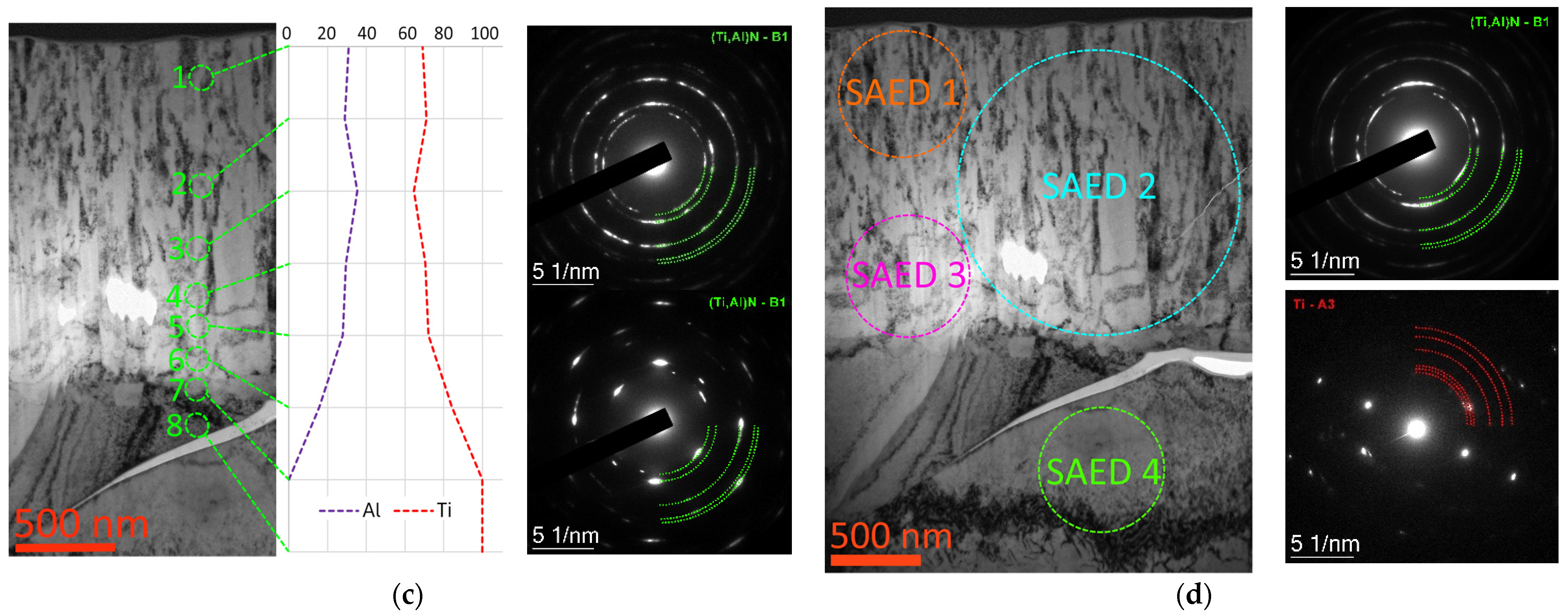
- The aluminum content in the coatings decreases from 94.2 at.% for the sample located directly opposite the evaporator with an Al cathode to 10.3 at.% for the sample located opposite the evaporator with a Ti cathode. Moreover, the titanium content increases from 7.6 at.% to 89.7 at.%. The sample occupying an intermediate position between the aluminum and titanium plasma flows has a dominant titanium content (69.5 at.%) and a lower aluminum content (30.5 at.%).
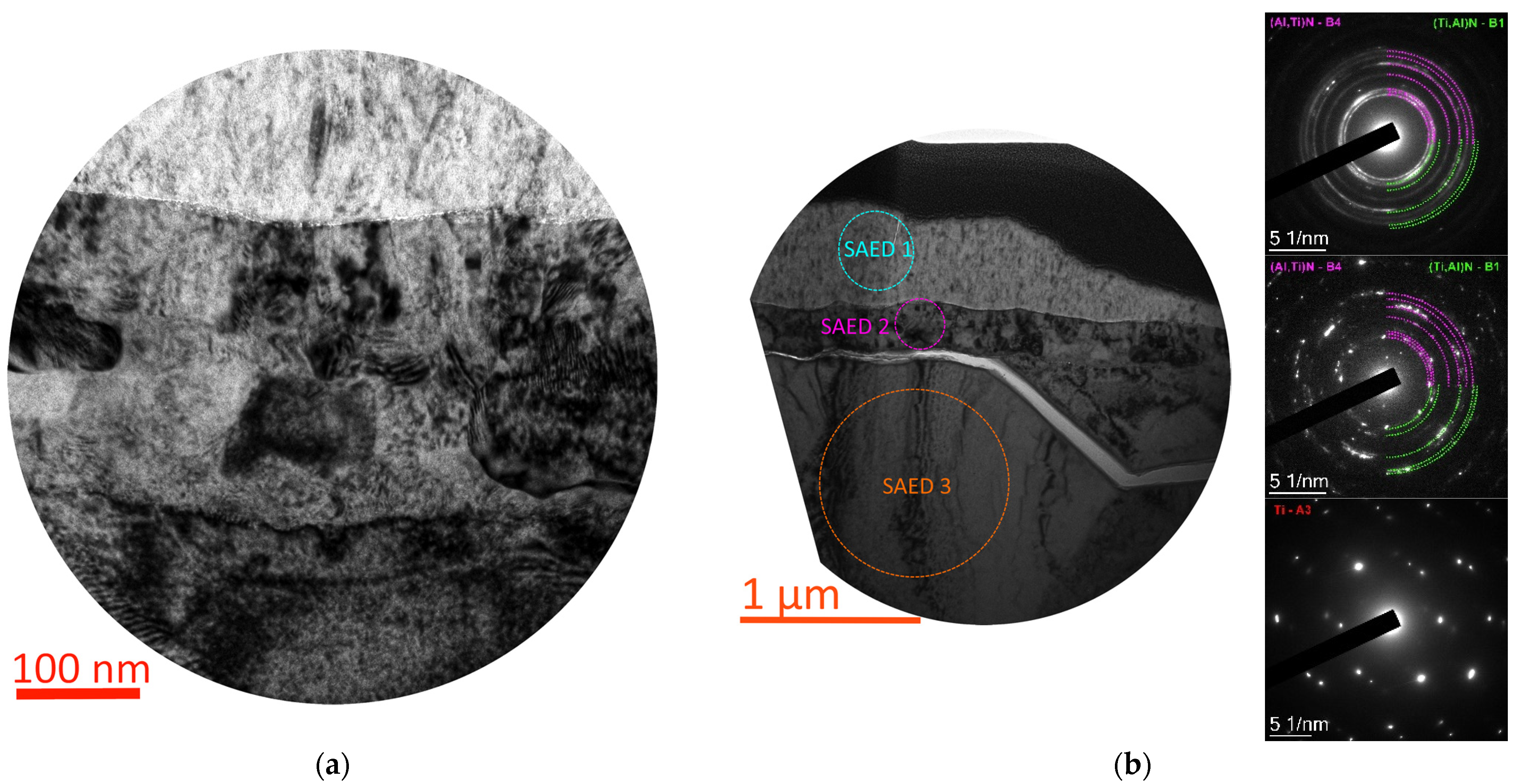
- In the coating deposited on the sample located opposite the aluminum cathode, a nitrided layer of about 250 nm in thickness is formed in the substrate.
- The results of hardness changes show that the coating on the sample occupying an intermediate position has the maximum hardness (32.3 ± 1.7 GPa). The coating on the sample located opposite the aluminum cathode has a hardness of 16.7 ± 0.8 GPa. The hardness of the coating on the sample located opposite the titanium cathode is 28.5 ± 1.1 GPa.
- The results of the study of the resistance to destruction in the scratch test correlate sufficiently with the hardness data. The coating on the sample occupying an intermediate position has the best resistance to destruction (complete destruction is not observed under a load of 40 N). The coating on the sample located opposite the aluminum cathode has the lowest fracture strength (it is destroyed under a load of LC2 = 14 N). The destruction of the coating on the sample located opposite the titanium cathode occurs under a load of 28 N.
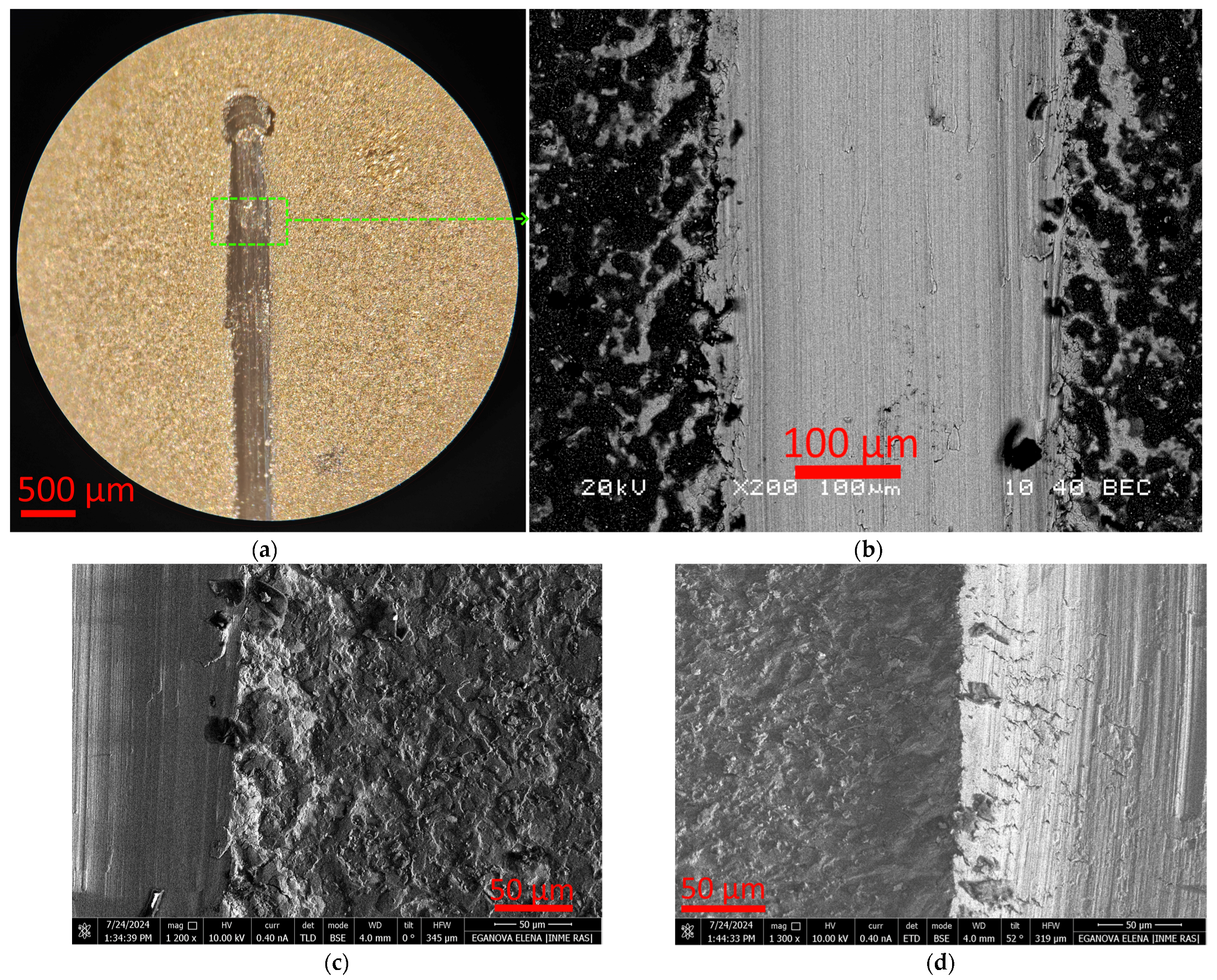
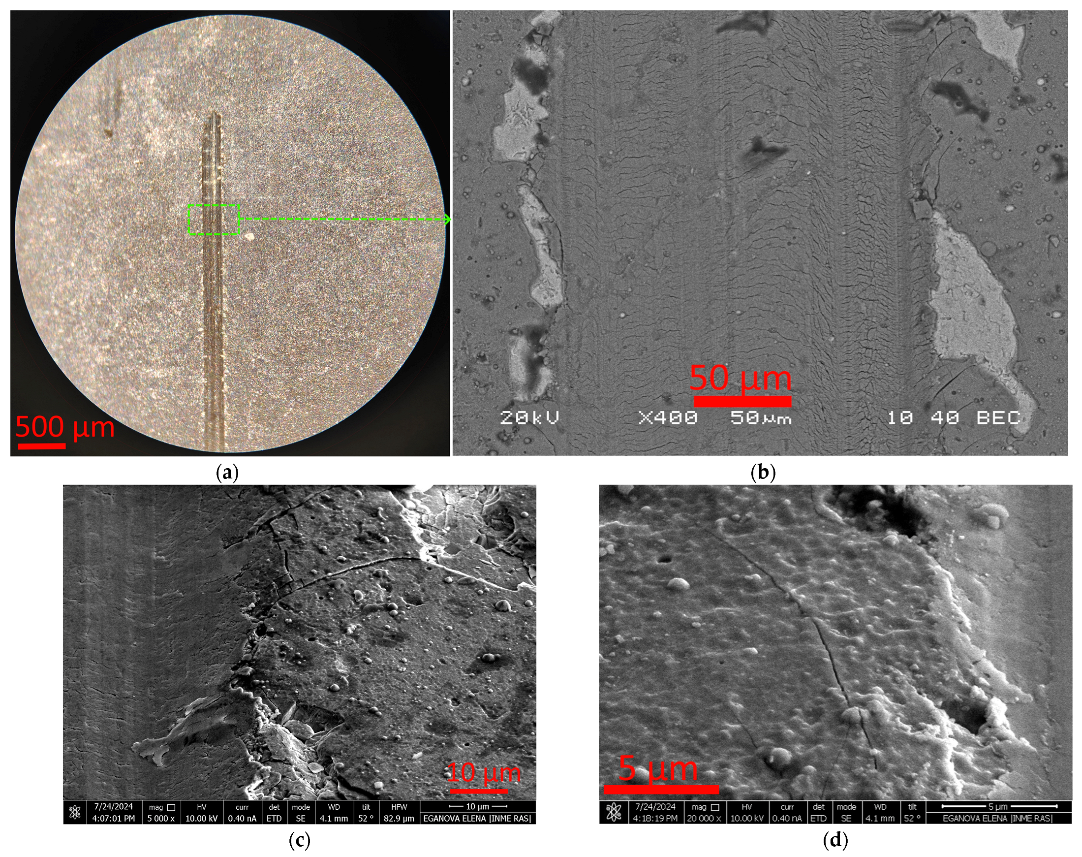
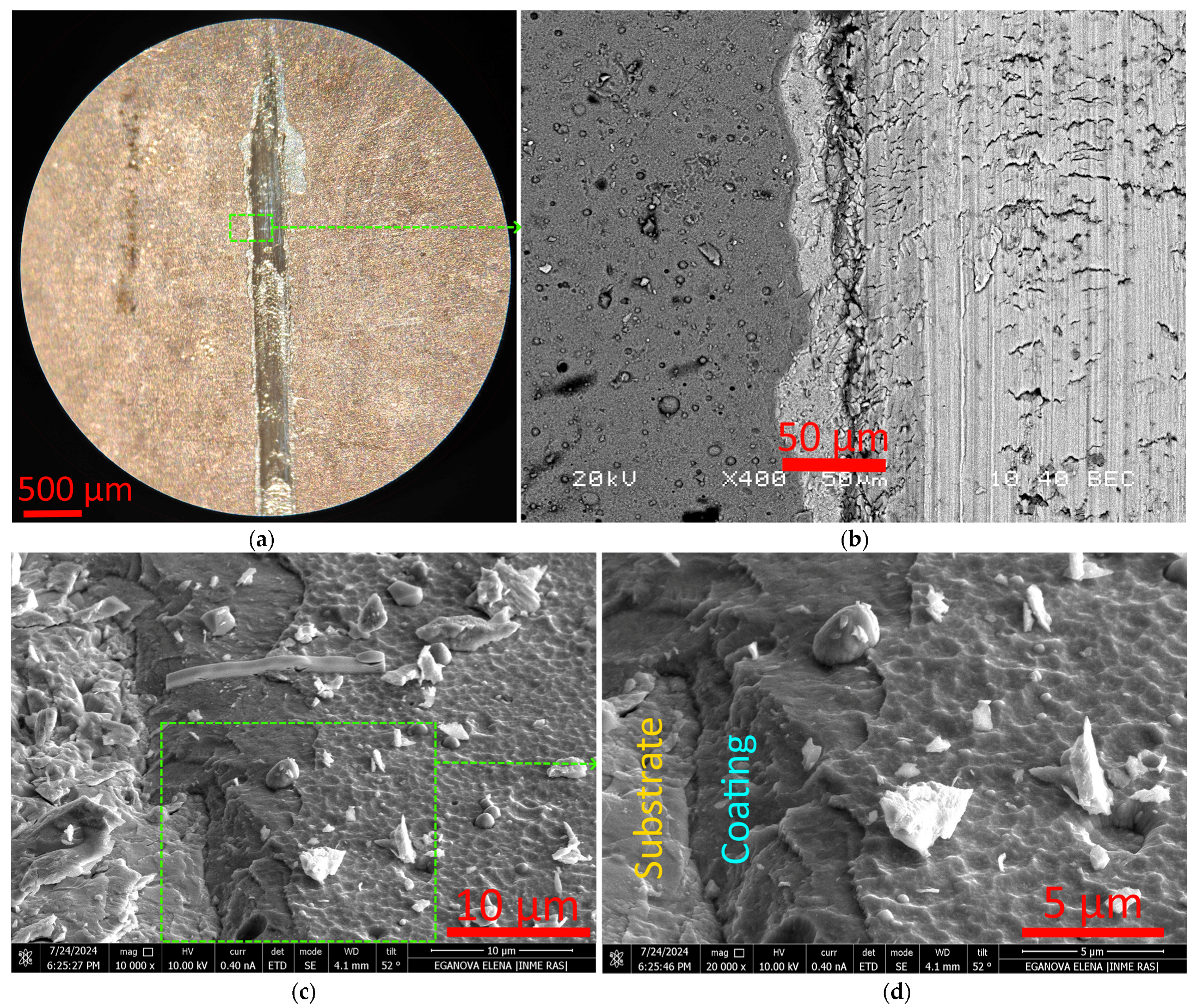
- The coating on the sample located opposite the aluminum cathode shows a dent in the coating, accompanied by partial chipping along the groove boundaries. The coating on the sample occupying an intermediate position is characterized by brittle fracture with the formation of a crack network in the depth of the scribing groove and fragmentary chips at the groove boundary up to 50 μm wide. The coating on the sample located opposite the titanium cathode is characterized by fracture as a result of extensive delamination.
Author Contributions
Funding
Institutional Review Board Statement
Informed Consent Statement
Data Availability Statement
Acknowledgments
Conflicts of Interest
References
- Daalder, J.E. Components of cathode erosion in vacuum arcs. J. Phys. D Appl. Phys. 1976, 9, 2379–2395. [Google Scholar] [CrossRef]
- Anders, A. Cathodic Arcs; Springer Science Business Media LLC: New York, NY, USA, 2008. [Google Scholar]
- Aksenov, I.I.; Konovalov, I.I.; Pershin, V.F.; Khoroshikh, V.M.; Shpilinskii, L.F. Low-pressure arc cathode erosion. High Temp. 1988, 26, 315–318. [Google Scholar]
- Baouchi, A.W.; Perry, A.J. A study of the macroparticle distribution in cathodic-arc- evaporated TiN films. Surf. Coat. Technol. 1991, 49, 253–257. [Google Scholar] [CrossRef]
- Grigoriev, S.; Vereschaka, A.; Zelenkov, V.; Sitnikov, N.; Bublikov, J.; Milovich, F.; Andreev, N.; Mustafaev, E. Specific features of the structure and properties of arc-PVD coatings depending on the spatial arrangement of the sample in the chamber. Vacuum 2022, 200, 111047. [Google Scholar] [CrossRef]
- Tuchinda, K.; Damkam, C.; Preechapongkij, W.; Ratanabunlang, R.; Wittayapairot, N. The effect of substrate location arrangement in the PVD deposition chamber on the mechanical properties of the coatings. In Proceedings of the Minerals, Metals and Materials Society—3rd International Conference on Processing Materials for Properties 2008, Bangkok, Thailand, 7–10 December 2008; Volume 2, pp. 1167–1174. [Google Scholar]
- Vuchkov, T.; Evaristo, M.; Yaqub, T.B.; Cavaleiro, A. The effect of substrate location on the composition, microstructure and mechano-tribological properties of W-S-C coatings deposited by magnetron sputtering. Surf. Coat. Technol. 2020, 386, 125481. [Google Scholar] [CrossRef]
- Vardanyan, E.L.; Kireev, R.M.; Budilov, V.V. Synthesis of coatings based on intermetallic titanium-aluminum by vacuum arc deposition. In Proceedings of the International Symposium on Discharges and Electrical Insulation in Vacuum, ISDEIV, Tomsk, Russia, 2–7 September 2012; pp. 549–551, Art. No 6412577. [Google Scholar]
- Vardanyan, E.L.; Kireev, R.M.; Budilov, V.V.; Ramaznov, K.N. Producing of coatings based on intermetallic Tix-Aly on the surface of the part by using vacuum arc plasma. In Proceedings of the International Symposium on Discharges and Electrical Insulation in Vacuum, ISDEIV, Mumbai, India, 28 September–3 October 2014; pp. 541–543, Art. No 6961739. [Google Scholar]
- Zhang, Z.; Zhang, L.; Yuan, H.; Qiu, M.; Zhang, X.; Liao, B.; Zhang, F.; Ouyang, X. Tribological Behaviors of Super-Hard TiAlN Coatings Deposited by Filtered Cathode Vacuum Arc Deposition. Materials 2022, 15, 2236. [Google Scholar] [CrossRef]
- PalDey, S.; Deevi, S.C. Single layer and multilayer wear resistant coatings of (Ti,Al)N: A review. Mater. Sci. Eng. A 2003, 342, 58–79. [Google Scholar] [CrossRef]
- Sveen, S.; Andersson, J.; M’Saoubi, R.; Olsson, M. Scratch adhesion characteristics of PVD TiAlN deposited on high speed steel, cemented carbide and PCBN substrates. Wear 2013, 308, 133–141. [Google Scholar] [CrossRef]
- Han, J.G.; Yoon, J.S.; Kim, H.J.; Song, K. High temperature wear resistance of (TiAl)N films synthesized by cathodic arc plasma deposition. Surf. Coat. Technol. 1996, 86–87, 82–87. [Google Scholar] [CrossRef]
- Lin, K.L.; Hwang, M.Y.; Wu, C.D. The deposition and wear properties of cathodic arc plasma deposition TiAlN deposits. Mater. Chem. Phys. 1996, 46, 77–83. [Google Scholar] [CrossRef]
- Kimura, A.; Hasegawa, H.; Yamada, K.; Suzuki, T. Metastable Ti1-xAlxN films with different Al content. J. Mater. Sci. Lett. 2000, 19, 601–602. [Google Scholar] [CrossRef]
- Tanaka, Y.; Gür, T.M.; Kelly, M.; Hagstrom, S.B.; Ikeda, T. Structure and properties of (Ti1-xAlx)N films prepared by reactive sputtering. Thin Solid Film. 1993, 228, 238–241. [Google Scholar] [CrossRef]
- Wahlström, U.; Hultman, L.; Sundgren, J.-E.; Adibi, F.; Petrov, I.; Greene, J.E. Crystal growth and microstructure of polycrystalline Ti1-xAlxN alloy films deposited by ultra-high-vacuum dual-target magnetron sputtering. Thin Solid Films 1993, 235, 62–70. [Google Scholar] [CrossRef]
- Musil, J.; Hrubý, H. Superhard nanocomposite Ti1−xAlxN films prepared by magnetron sputtering. Thin Solid Films 2000, 365, 104–109. [Google Scholar] [CrossRef]
- Coll, B.F.; Fontana, R.; Gates, A.; Sathrum, P. (Ti,Al)N advanced films prepared by arc process. Mater. Sci. Eng. A 1991, 140, 816–824. [Google Scholar] [CrossRef]
- Elmkhah, H.; Fattah-alhosseini, A.; Babaei, K.; Abdollah-Zadeh, A.; Mahboubi, F. Correlation between the Al content and corrosion resistance of TiAlN coatings applied using a PACVD technique. J. Asian Ceram. Soc. 2020, 8, 72–80. [Google Scholar] [CrossRef]
- Steffens, H.-D.; Mack, M.; Moehwald, K.; Reichel, K. Reduction of droplet emission in random arc technology. Surf. Coat. Technol. 1991, 46, 65–74. [Google Scholar] [CrossRef]
- Steel Grade ERTi-1 Chemical Information, Mechanical Properties. Available online: https://www.steel-grades.com/index.php?m=pdfmetal&c=index&a=pdf&catid=85&id=11519?ERTi-1-Datasheet.pdf (accessed on 14 August 2024).
- Grigoriev, S.; Vereschaka, A.; Milovich, F.; Sitnikov, N.; Andreev, N.; Bublikov, J.; Kutina, N. Investigation of the properties of the Cr,Mo-(Cr,Mo,Zr,Nb)N-(Cr,Mo,Zr,Nb,Al)N multilayer composite multicomponent coating with nanostructured wear-resistant layer. Wear 2021, 468–469, 203597. [Google Scholar] [CrossRef]
- Vereschaka, A.A.; Bublikov, J.I.; Sitnikov, N.N.; Oganyan, G.V.; Sotova, C.S. Influence of nanolayer thickness on the performance properties of multilayer composite nano-structured modified coatings for metal-cutting tools. Int. J. Adv. Manuf. Technol. 2018, 95, 2625–2640. [Google Scholar] [CrossRef]
- Grigoriev, S.; Vereschaka, A.; Milovich, F.; Migranov, M.; Andreev, N.; Bublikov, J.; Sitnikov, N.; Oganyan, G. Investigation of the tribological properties of Ti-TiN-(Ti,Al,Nb,Zr)N composite coating and its efficiency in increasing wear resistance of metal cutting tools. Tribol. Int. 2021, 164, 107236. [Google Scholar] [CrossRef]
- Vereschaka, A.S.; Grigoriev, S.N.; Sotova, E.S.; Vereschaka, A.A. Improving the efficiency of the cutting tools made of mixed ceramics by applying modifying nano-scale multilayered coatings. Adv. Mat. Res. 2013, 712–715, 391–394. [Google Scholar]
- Volosova, M.; Grigoriev, S.; Metel, A.; Shein, A. The Role of Thin-Film Vacuum-Plasma Coatings and Their Influence on the Efficiency of Ceramic Cutting Inserts. Coatings 2018, 8, 287. [Google Scholar] [CrossRef]
- Grigoriev, S.N.; Volosova, M.A.; Vereschaka, A.A.; Sitnikov, N.N.; Milovich, F. Properties of (Cr,Al,Si)N-(DLC-Si) composite coatings deposited on a cutting ceramic substrate. Ceram. Int. 2020, 46, 18241–18255. [Google Scholar] [CrossRef]
- Grigoriev, S.; Vereschaka, A.; Milovich, F.; Sitnikov, N.; Seleznev, A.; Sotova, C.; Bublikov, J. Influence of the yttrium cathode arc current on the yttrium content in the (Ti, Y, Al) N coating and the coating properties. Vacuum 2024, 222, 113028. [Google Scholar] [CrossRef]
- Grigoriev, S.; Vereschaka, A.; Zelenkov, V.; Sitnikov, N.; Bublikov, J.; Milovich, F.; Andreev, N.; Sotova, C. Investigation of the influence of the features of the deposition process on the structural features of microparticles in PVD coatings. Vacuum 2022, 202, 111144. [Google Scholar] [CrossRef]
- ASTM C1624-05(2015); Standard Test Method for Adhesion Strength and Mechanical Failure Modes of Ceramic Coatings by Quantitative Single Point Scratch Testing. ASTM International: West Conshohocken, PA, USA, 2010.
- Buckle, H.; Westbrook, J.H.; Conrad, H. (Eds.) The Science of Microhardness Testing and its Research Applications; American Society for Metals: Russell Township, OH, USA, 1973; p. 453. [Google Scholar]
- Peggs, G.N.; Leigh, I.C. Recommended Procedure for Micro-Indentation Vickers Hardness Test, Report MOM62; National Physical Laboratory: Middlesex, UK, 1983. [Google Scholar]
- Chen, J.; Bull, S.J. On the factors affecting the critical indenter penetration for measurement of coating hardness. Vacuum 2009, 83, 911–920. [Google Scholar] [CrossRef]
- Vingsbo, O.; Hogmark, S.; Jönsson, B.; Ingemarsson, B.; Blau, P.J.; Lawn, B.R. (Eds.) Microindentation Techniques in Materials Science and Engineering; ASTM: Philadelphia, PA, USA, 1986. [Google Scholar]
- Burnett, P.J.; Rickerby, D.S. The mechanical properties of wear-resistant coatings I: Modelling of hardness behaviour. Thin Solid Films 1987, 148, 41–50. [Google Scholar] [CrossRef]
- Chen, L.; Du, Y.; Wang, A.J.; Wang, S.Q.; Zhou, S.Z. Effect of Al content on microstructure and mechanical properties of Ti-Al-Si-N nanocomposite coatings. Int. J. Refract. Met. Hard Mater. 2009, 27, 718–721. [Google Scholar] [CrossRef]
- Zou, C.W.; Zhang, J.; Xie, W.; Shao, L.X.; Fu, D.J. Structure and mechanical properties of Ti-Al-N coatings deposited by combined cathodic arc middle frequency magnetron sputtering. J. Alloys Compd. 2011, 509, 1989–1993. [Google Scholar] [CrossRef]
- Chen, L.; Paulitsch, J.; Du, Y.; Mayrhofer, P.H. Thermal stability and oxidation resistance of Ti-Al-N coatings. Surf. Coat. Technol. 2012, 206, 2954–2960. [Google Scholar] [CrossRef]
- Fan, G.; Zhang, J.; Zhang, P.; Du, J.; Xu, C.; Yi, M.; Zhang, G. Effect of Al Content on the Wear Evolution of Ti1-xAlxN-Coated Tools Milling Ti-6Al-4V Alloy. Micromachines 2023, 14, 1228. [Google Scholar] [CrossRef] [PubMed]
- Vereschaka, A.; Milovich, F.; Migranov, M.; Andreev, N.; Alexandrov, I.; Muranov, A.; Mikhailov, M.; Tatarkanov, A. Investigation of the tribological and operational properties of (Mex,Moy,Al1-(x+y))N (Me –Ti, Zr or Cr) coatings. Tribol. Int. 2022, 165, 107305. [Google Scholar] [CrossRef]
- Larijani, M.M.; Manouchehrian, M.; Seyedi, H.; Yari, M. Corrosion behavior of solid solution (Ti,Al)N as a function of Al concentration. Cryst. Res. Technol. 2012, 47, 834–840. [Google Scholar] [CrossRef]
- Sahoo, D.K.; Pradeep, A.M.V.; Mohanty, B.S.; Jaswanth, A. Influence of inductive heating on coating geometry during deposition of AISI 316 stainless steel over EN8 carbon steel using friction surfacing process. Mater. Today 2020, 27, 1641–1650. [Google Scholar] [CrossRef]
- Garcia, J.; Pitonak, R.; Weissenbacher, R.; Köpf, A. Production and characterization of wear resistant Ti(C,N) coatings manufactured by modified chemical vapor deposition process. Surf. Coat. Technol. 2010, 205, 2322–2327. [Google Scholar] [CrossRef]
- Ji, X.; Wang, L.J.; Zhang, C.M.; Mi, Y.M. Heating and Time Processes on Growth and Adhesive Property of Ta-Mo Coatings. Mater. Manuf. Process. 2016, 31, 1269–1273. [Google Scholar] [CrossRef]
- Sun, F.; Liu, X.-L.; Luo, S.-Q.; Xiang, D.-D.; Ba, D.-C.; Lin, Z.; Song, G.-Q. Duplex treatment of arc plasma nitriding and PVD TiN coating applied to dental implant screws. Surf. Coat. Technol. 2022, 439, 128449. [Google Scholar] [CrossRef]
- Tan, C.; Zhou, K.; Kuang, T.; Li, Y.; Ma, W. Novel performances of in situ plasma nitriding-PVD duplex-treated nanocrystalline TiN coatings. Surf. Eng. 2018, 34, 520–526. [Google Scholar] [CrossRef]
- Nolan, D.; Huang, S.W.; Leskovsek, V.; Braun, S. Sliding wear of titanium nitride thin films deposited on Ti-6Al-4V alloy by PVD and plasma nitriding processes. Surf. Coat. Technol. 2006, 200, 5698–5705. [Google Scholar] [CrossRef]
- Durst, O.; Ellermeier, J.; Berger, C. Influence of plasma-nitriding and surface roughness on the wear and corrosion resistance of thin films (PVD/PECVD). Surf. Coat. Technol. 2008, 203, 848–854. [Google Scholar] [CrossRef]
- Alkan, S.; Gök, M.S. Influence of plasma nitriding pre-treatment on the corrosion and tribocorrosion behaviours of PVD CrN, TiN and AlTiN coated AISI 4140 steel in seawater. Lubr. Sci. 2022, 34, 67–83. [Google Scholar] [CrossRef]
- Liu, J.-K.; Liu, I.-H.; Liu, C.; Chang, C.-J.; Kung, K.-C.; Liu, Y.-T.; Lee, T.-M.; Jou, J.-L. Effect of titanium nitride/titanium coatings on the stress corrosion of nickel-titanium orthodontic archwires in artificial saliva. Appl. Surf. Sci. 2014, 317, 974–981. [Google Scholar] [CrossRef]
- Liu, Y.; Wang, D.; Deng, C.; Huo, L.; Wang, L.; Cao, S. Feasibility study on preparation of coatings on Ti-6Al-4V by combined ultrasonic impact treatment and electrospark deposition. Mater. Des. 2014, 63, 488–492. [Google Scholar] [CrossRef]
- Zykova, A.; Safonov, V.; Walkowich, J.; Rogowska, R.; Yakovin, S. Corrosion properties of nitride, oxide and multilayer coatings on stainless steel and titanium-based substrates. J. Phys. Conf. Ser. 2010, 223, 012024. [Google Scholar] [CrossRef]
- Zhang, H.; Zheng, S.H.; Yang, L.; Jin, C.J.; Pan, L.Y. Investigation of Fracture Performance and Interface Stress Behavior of Zn-Zn-Al Multilayer Coating-304 Stainless Steel Substrate System. J. Mater. Civ. Eng. 2022, 34, 04021472. [Google Scholar] [CrossRef]
- Vereschaka, A.; Grigoriev, S.; Milovich, F.; Sitnikov, N.; Migranov, M.; Andreev, N.; Bublikov, J.; Sotova, C. Investigation of tribological and functional properties of Cr,Mo-(Cr,Mo)N-(Cr,Mo,Al)N multilayer composite coating. Tribol. Int. 2021, 155, 106804. [Google Scholar] [CrossRef]
- Long, R.; Dunn, M.L. Channel cracks in atomic-layer and molecular-layer deposited multilayer thin film coatings. J. Appl. Phys. 2014, 115, 233514. [Google Scholar] [CrossRef]
- Voevodin, A.A.; Walck, S.D.; Zabinski, J.S. Architecture of multilayer nanocomposite coatings with super-hard diamond-like carbon layers for wear protection at high contact loads. Wear 1997, 203–204, 516–527. [Google Scholar] [CrossRef]


| Coating designation | T2 | T7 | T12 |
| Coating thickness, µm | 0.9–1.5 | 2.0–2.3 | 2.8–3.4 |
Disclaimer/Publisher’s Note: The statements, opinions and data contained in all publications are solely those of the individual author(s) and contributor(s) and not of MDPI and/or the editor(s). MDPI and/or the editor(s) disclaim responsibility for any injury to people or property resulting from any ideas, methods, instructions or products referred to in the content. |
© 2024 by the authors. Licensee MDPI, Basel, Switzerland. This article is an open access article distributed under the terms and conditions of the Creative Commons Attribution (CC BY) license (https://creativecommons.org/licenses/by/4.0/).
Share and Cite
Sotova, C.; Volosova, M.; Vereschaka, A.; Bublikov, Y.; Milovich, F.; Seleznev, A.; Shmakov, I.; Grigoriev, S. Features of the Influence of the Arrangement of Parts in the Chamber of Installation During Vacuum Arc Deposition on the Properties of Coatings. Appl. Sci. 2024, 14, 10634. https://doi.org/10.3390/app142210634
Sotova C, Volosova M, Vereschaka A, Bublikov Y, Milovich F, Seleznev A, Shmakov I, Grigoriev S. Features of the Influence of the Arrangement of Parts in the Chamber of Installation During Vacuum Arc Deposition on the Properties of Coatings. Applied Sciences. 2024; 14(22):10634. https://doi.org/10.3390/app142210634
Chicago/Turabian StyleSotova, Catherine, Marina Volosova, Alexey Vereschaka, Yuri Bublikov, Filipp Milovich, Anton Seleznev, Ilya Shmakov, and Sergey Grigoriev. 2024. "Features of the Influence of the Arrangement of Parts in the Chamber of Installation During Vacuum Arc Deposition on the Properties of Coatings" Applied Sciences 14, no. 22: 10634. https://doi.org/10.3390/app142210634
APA StyleSotova, C., Volosova, M., Vereschaka, A., Bublikov, Y., Milovich, F., Seleznev, A., Shmakov, I., & Grigoriev, S. (2024). Features of the Influence of the Arrangement of Parts in the Chamber of Installation During Vacuum Arc Deposition on the Properties of Coatings. Applied Sciences, 14(22), 10634. https://doi.org/10.3390/app142210634