Article

A Virtual View Acquisition Technique for Complex Scenes of Monocular Images Based on Layered Depth Images

College of Electronic and Information Engineering, Changchun University of Science and Technology, Changchun 130022, China
*
Author to whom correspondence should be addressed.
Appl. Sci. 2024, 14(22), 10557; https://doi.org/10.3390/app142210557
Submission received: 13 September 2024 / Revised: 13 November 2024 / Accepted: 14 November 2024 / Published: 15 November 2024

Abstract

:
With the rapid development of stereoscopic display technology, how to generate high-quality virtual view images has become the key in the applications of 3D video, 3D TV and virtual reality. The traditional virtual view rendering technology maps the reference view into the virtual view by means of 3D transformation, but when the background area is occluded by the foreground object, the content of the occluded area cannot be inferred. To solve this problem, we propose a virtual view acquisition technique for complex scenes of monocular images based on a layered depth image (LDI). Firstly, the depth discontinuities of the edge of the occluded area are reasonably grouped by using the multilayer representation of the LDI, and the depth edge of the occluded area is inpainted by the edge inpainting network. Then, the generative adversarial network (GAN) is used to fill the information of color and depth in the occluded area, and the inpainting virtual view is generated. Finally, GAN is used to optimize the color and depth of the virtual view, and the high-quality virtual view is generated. The effectiveness of the proposed method is proved by experiments, and it is also applicable to complex scenes.

1. Introduction

With the development of display technology and the popularity of 2K screens, 4K screens and even 8K screens, people’s pursuit of visual sense has become higher. Only clearer picture quality experience and fuller color enjoyment can fully satisfy people’s exploration of the objective world scene, and the three-dimensional (3D) expression of the scene can better interpret the world we know. The rise of 3D film, VR and driverless technology represents great progress in the exploration of new ways of presentation and shows the infinite potential of 3D display technology [1]. Three-dimensional display is very attractive to researchers because of its features of dense viewpoints and realistic views, but the problem of how to effectively obtain high-quality dense viewpoints has not been solved, which makes the popularization of 3D display technology limited.
In the early new view synthesis methods [2,3,4], geometric object information between multi-view images was always used. There were also some researchers who used hardware camera array for dense views acquisition, but this was limited by the high cost, the large size of the cameras and the complexity of the hardware system and so on, so the dense camera array model cannot be realized. Many classical virtual viewpoint rendering techniques [5,6,7] are faced with problems of requiring high-complexity models or small baselines. The multi-plane image (MPI) [8,9] improves the perspective, but it has more restrictions on the input images and is easy to produce artifacts on the inclined surfaces.
With the rapid development of computer hardware and the generation of massive available training data, deep neural networks have made great progress in the field of computer vision. In many early studies on virtual view using deep learning methods [10,11,12], since only the convolutional neural network (CNN) was used for simple data synthesis, the edges of objects in the synthesized images were very fuzzy. In the method combining geometric structure and deep learning [13], the input multi-view image was used to estimate the geometric structure between views. However, in many cases, we cannot obtain a large number of effective multi-view images, and the use of monocular images as the input of the network is more extensive in practical applications.
The existing synthesis methods for virtual view through monocular images [14,15] can usually only generate images of single specific viewpoints. Recently, many researchers used the layered representation of images [16,17] to predict virtual views. They combined the depth estimation of images [18,19] with the layered representation, and then used a generative adversarial network (GAN) for inpainting of the occluded areas in virtual views, so as to realize the synthesis of new views. In this paper, the method similar to [18,19] is also adopted for virtual view estimation of monocular images with complex depth information.
Monocular depth estimation: the CNN [20,21,22] has been used to obtain high-quality depth images of monocular images, which improves the accuracy of depth images. However, these methods mainly improve the learning ability by increasing the number of network layers, which limits the accuracy of the depth images obtained. Therefore, researchers began to combine CNN architecture based on monocular depth estimation with other geometric constraint information, such as the conditional random field (CRF) model [23,24] and regression forest [25,26,27]. In recent work, semantic information has been used to further improve the quality of depth estimation [28,29]. The method we adopted was to improve the depth estimation ability by using semantic segmentation information [30]. The extracted feature information was integrated by semantic segmentation-depth estimation subnets and the multi-scale feature fusion module, and the network was trained by the generable dataset of [31] so as to reduce the limit on the type range of the input images.
Layered depth image (LDI): The concept of layered depth image first appeared in [32]. It can represent the scene information in the single input view by multilayer RGB-D, which can be considered an efficient image-based rendering method. It can be used to deal with the efficient image rendering in the case of view disturbance and solve the problem of filling the content of occluded areas caused by the change in perspective. The interlayer pixels of LDI have 4-connectivity, while zero or one neighborhood can be accommodated in each of its basic orientation positions, and the values of color and depth can be stored in each LDI pixel. Hedman et al. [33,34] used more sophisticated heuristics for the inpainting of occluded areas. Tulsiani et al. [35] constructed a two-layer context-supervised representation method to solve the problem of insufficient ground true data. Different from the above work, in our layered depth image, the number of layers is not limited, which is determined according to the complexity of the scene depth. Moreover, networks no longer need to search the whole world through this layered representation, which greatly improves the working efficiency of the networks.
Restoration of color and depth based on CNN: The purpose of image inpainting is to reasonably fill the color information [36,37] and depth information of the occluded area in the background. Khot et al. [38,39] used the diffusion method to first identify the linear structure in the neighborhood, and then the linear structure was spread to the missing area for inpainting. In this way, however, it cannot avoid using the information in the foreground for content filling. Simonyan [40,41] proposed the sample-based method for inpainting of the information of color and depth. The depth information and edge detection information were effectively combined with the content of structure and texture, and the occluded area was well filled and less affected by the foreground information. In the era of deep learning, the ability of using CNNs to predict unknown information in known areas has been widely recognized. Image inpainting is usually completed through CNNs [42], a GAN [43] especially is also used in various image prediction tasks. The methods in [44,45,46] firstly predict the edge contour of the occluded area, and then use the edge contour to guide the content generation in the occluded area during image inpainting. Inspired by the above methods, the phased method is also adopted in the inpainting of the information of color and depth of the occluded area. However, the difference is that we refer to the method of [47] and use LDI for partial inpainting of the background area and occluded area at the depth discontinuity, so as to reduce the time pressure brought by the network depth. At the same time, in order to improve the inpainting ability of the occluded area, the edge information is used for the inpainting of the information of color and depth, respectively, which is also a paving for the subsequent work. Recently, an additional GAN model was introduced in the work of [16] to establish a relationship between the regional consistency of color information and depth information, which is also used by us to further improve the quality of the image of the generated occluded area.

2. Materials and Methods

In this paper, the single RGB image is used as the input to obtain the virtual view, and the depth estimation network is used to obtain the RGB-D image corresponding to the input image (Section 2.1). Then, the RGB-D image is mapped to the LDI representation. Compared with the previous single-layer depth representation, the LDI was used for multilayer depth representation so as to further utilize the details of the parallax region to generate new geometry for the occluded area (Section 2.2). For newly generated pixels in the occluded area, we filled them with color information and depth information through the GAN (Section 2.3). Finally, the above local color information and depth information after inpainting were integrated in turn, and the integrated view was optimized by using the method of deep learning so that high-quality virtual views were generated (Section 2.4).
The overall frame of the virtual viewpoint image generation is shown in Figure 1. Firstly, depth-related information was obtained from the input single RGB image. Then, all kinds of constraints extracted were processed through the edge inpainting network, color inpainting network and depth inpainting network, respectively, to obtain the virtual viewpoint image. Finally, the optimized network was used to further optimize the image and output high-quality virtual view image.
To illustrate the method proposed in this paper more clearly, the implementation logic of virtual view acquisition technology is shown in Algorithm 1.
Algorithm 1 Virtual view generation algorithm
1.   Inputting RGB color image.
2.     Generating semantic segmentation image of RGB image and defining semantic segmentation label M S S .
3.     Generating depth image of RGB image.
4.   Elevating depth image to LDI for multilayer representation.
5.   Preprocessing depth image.
6.     Sharpening depth image and determining discontinuous pixel segment.
7.      Aligning RGB image with depth image.
8.     Eliminating spurious response (continuous pixel segment less than 15 pixels) and determining the number of discontinuous layer N L D I .
9.   Inpainting layered image.
10.     for N = 1 ; N < = N L D I ; N + +
11.          Breaking discontinuous points to generate composite area. The fore ground area, background area and outline of occluded area are determined, and the occluded area is filled by the iterative flood filling algorithm.
12.          Inpainting image edge of occluded area.
13.          Inpainting of color and depth of occluded area.
14.      end for
15.   Combining foreground area, background area and occluded area to generate new view angle image.
16.   Optimizing virtual view of new view angle image.
17.     Determining semantic segmentation label M S S in the new view angle image. The semantic segmentation label is applied to the new view angle image and its depth image.
18.     for M = 1 ; M < = M S S ; M + +
19.          Optimizing new view angle image.
20.     end for
21.   Outputting virtual view image.
The proposed virtual view generation technique is described in detail in the following sections.

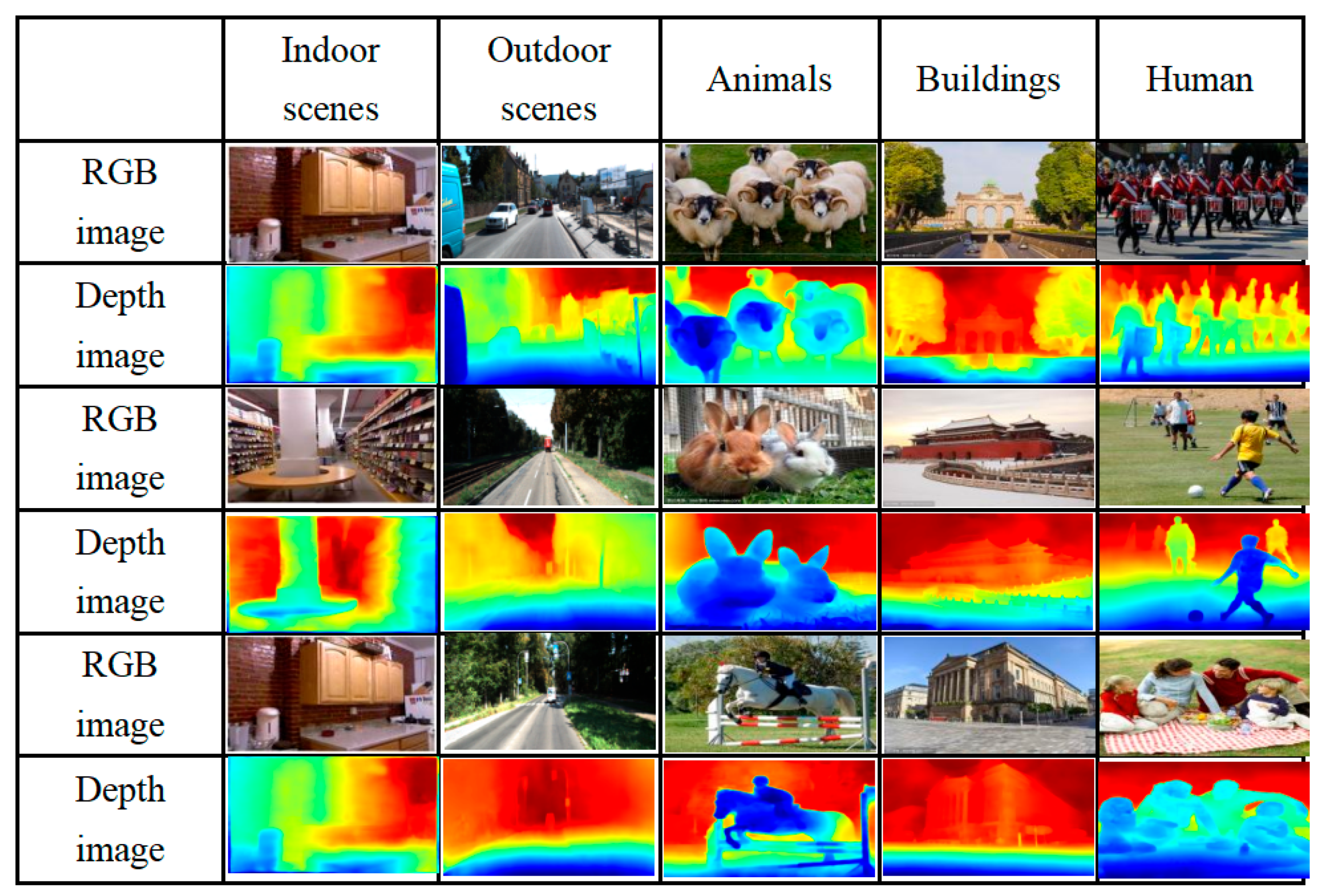
2.1. Depth Estimation

High-quality depth images are helpful to the synthesis of virtual views. In this paper, based on the ResNet50 [48] network model, the extracted feature information is processed and fused through semantic segmentation-depth estimation subnet and multi-scale feature fusion module. Furthermore, guidance is given to depth estimation subnets by semantic segmentation subnets, so as to improve quality of depth image. At the same time, the generalization dataset of [31] is used to train the network, so as to reduce the restriction on the type range of the input images. As shown in Figure 2, depth estimation images of human, animals and scenes were obtained by using the proposed method in this paper, respectively. Experimental results show that the depth images obtained are of high quality, and this method is widely applicable to various types of scenes.

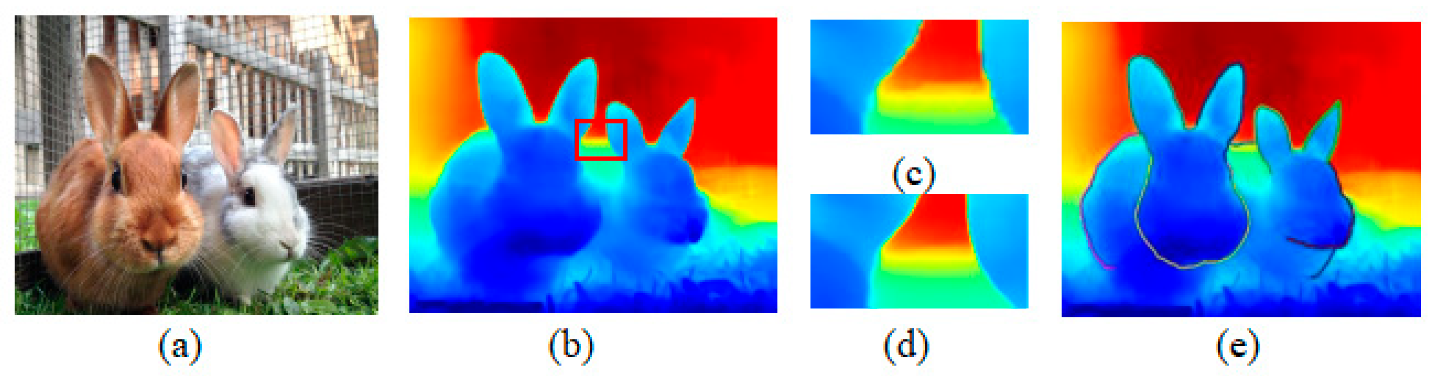
2.2. Generation of Layered Depth Image

As the prerequisite for LDI representation, the acquisition of high-quality depth images can be used for multilayer representation. The LDI contains a different number of depth pixels in each pixel position, and each pixel can be connected with 0 or 1 neighborhood pixel in four basic directions. This feature can be used to solve the occlusion problem caused by different perspectives in the scene. There are different kinds of objects in different scenes, which have different depths due to their position relationship. According to the discontinuity relationship of depth, image information can be divided into foreground information and background information. The aim of this study is to expand the invisible background information occluded in different perspectives, that is, to generate new pixel information in the parallax area.
Depth image preprocessing: When filling the occluded area through RGB-D images, the primary task is to effectively utilize the depth discontinuity between geometric objects; this is because the depth values usually change continuously inside the object, while the edge of the object will show very obvious discontinuity characteristics. However, due to the regularization characteristic of existing depth estimation algorithms based on neural networks, the discontinuity between edge pixels is blurred, which makes the depth image obtained too smooth. In order to make use of the discontinuity area of the depth edge effectively, a weighted pattern filter is used to sharpen the depth image. A histogram is used to count the number of pixels with the same intensity in the depth image, and then a weighted pattern filter is used on this basis. First, the local histogram H l o c a l u , d is defined as
H l o c a l ( u , d ) = v E ( u ) G z ( d F ( v ) ) G k ( u v )
where u is the reference pixel, d is the depth of the reference pixel and v is the pixel of its neighborhood. E u is the set of neighborhood pixels in the specified size window centered on point u . G z and G k are Gaussian kernel functions, and their standard deviations are δ z and δ k , respectively. z represents the value range, and k represents the spatial domain. By calculating the depth value of the reference pixel by specifying the neighborhood pixel within the window, the maximum value is set as the final solution F u of the weighted mode filter:
F ( u ) = arg max d H l o c a l ( u , d )
In order to ensure that the edge information in the image after weighted summing processing is clear, and the quality of the depth image is improved, the similarity of the inter-pixel in the depth image and its corresponding color image C u is used to carry out global pixel similarity exploration in H l o c a l u , d . The global histogram is expressed as H g l o b a l u , d :
H g l o b a l ( u , d ) = v E ( u ) G z ( C ( u ) C ( v ) ) G z ( d F ( v ) ) G k ( u v )
where z is the value range of the color image. In the color image, the closer the brightness between two pixels is, the larger the G z is. Therefore, the global final solution F g l o b a l u of the weighted mode filter can be obtained as follows:
F g l o b a l ( u ) = arg max d H g l o b a l ( u , d )
The smoothness of the filter is affected by the values of standard deviation δ z , δ k and δ z , where δ z = 3.0 , δ k = 8.0 and δ z = 6.0 are selected by experiment, and the window size is 7 pixels × 7 pixels. The input RGB image is shown in Figure 3a. The filtered results are shown in Figure 3b. In order to clearly compare the contents before and after weighted filtering, the area in the red box is locally enlarged, as shown in Figure 3d. The content corresponding to Figure 3d without weighted filtering is shown in Figure 3c. It can be clearly seen that the discontinuous edge of the image has been effectively defined after filtering.
The improved Canny edge detection algorithm is used to detect the edge of weighted filtered image, and the difference between adjacent pixels in the weighted filtered image is calculated at the same time, so that the depth discontinuous edge is determined. In the implementation process, edge fragments smaller than 15 pixels will be eliminated, and the local connectivity of the LDI will ensure that each discontinuous edge exists independently. The discontinuous depth edges are shown in Figure 3e.
Depth edge inpainting: In this paper, the monocular RGB image is the only input to obtain the virtual view. After depth estimation, the depth image of the input image can be obtained. However, the single depth image is not enough to obtain the virtual view, because it cannot store visual information and geometric content other than the visible object of the input RGB scene. In order to obtain the virtual view, we raised the image to the LDI for representation and created a multilayer representation of the scene based on the discontinuity of pixels between different objects in the scene. At the pixel point continuity, LDI pixels were completely connected with four adjacent pixels. At the pixel point discontinuity, the LDI pixels were not completely connected with four adjacent pixels. After the above operations, the depth discontinuities and discontinuous edge sets in the image were determined, and according to these discontinuous depth edges, the scene was divided into the foreground area and the background area. By expanding the background area, new geometric content was generated in the occluded area, so that the inpainting of the occluded area was realized. The divided areas are shown in Figure 4b:
In Figure 4, the foreground area, the occluded area and background area of the image can be clearly seen. Figure 4a is the input RBG image, and the red box is a selected discontinuous edge line. Figure 4b is the generated virtual view image without inpainting. The pink area is the foreground area, the gray area is the occluded area and the blue area is the background area. For the background area, it was preliminarily expanded according to the edge first, so that the content of the occluded area could be filled. Then, the iterative flood filling algorithm was used to initialize the color and depth of the filled content, and in order to avoid the problem caused by unconstrained extension, it was stipulated that the extended scope would not cross the intersection of the ends of two deep edges during the extended iteration. During pixel filling, forward extension was carried out according to the previously determined edge of the background area, and then 120 times of pixel iterations were carried out in the occluded area according to the LDI pixel using the 4-connectivity method. The pixel information in the filled occluded area will be further processed in Section 2.3.
The pixel information in the background area was used to synthesize the information of color and depth of the occluded area. The content of the synthesized occluded area was only limited by the pixel information in the background area and had nothing to do with the content of foreground area and other LDI layers. The edge of the background area was used as input to generate the edge of the occluded area using the edge inpainting network. Then, the edge information of the occluded area was used for further inpainting of the information of color and depth of the occluded area together with the information of color and depth of the background area, respectively. As the basis of the overall content inpainting, accurate edge information of the occluded area was helpful to better constrain the information of color and depth of the occluded area in the later inpainting. We used a two-stage edge connection network model similar to that proposed by Goodfellow et al. [49] for the inpainting of the edge lines of all occluded areas, respectively. The framework of the edge inpainting network adopted in this paper is shown in Figure 5.
In the edge inpainting network in Figure 5, G is the generator and D is the discriminator. In the generator, the input information was down-sampled twice, then the residual block with the sensitivity field of 205 was generated by expanding convolution, and finally the output image was restored to the size of the input image after up-sampling twice. In the discriminator, the 70 × 70 PatchGAN was adopted to crop the image into the size 70 × 70 for identification, then all the output values were averaged to predict the authenticity of the edge information.
The loss function of edge inpainting is defined as L e i , including adversarial loss and perceptual loss. The expression is as follows:
min G max D L e i = min G ( λ a d v max ( L a d v ) D + λ p e r L p e r )
where λ a d v and λ p e r are regularization parameters. In our experiments, λ a d v = 1.5 , and λ p e r = 9.7 .

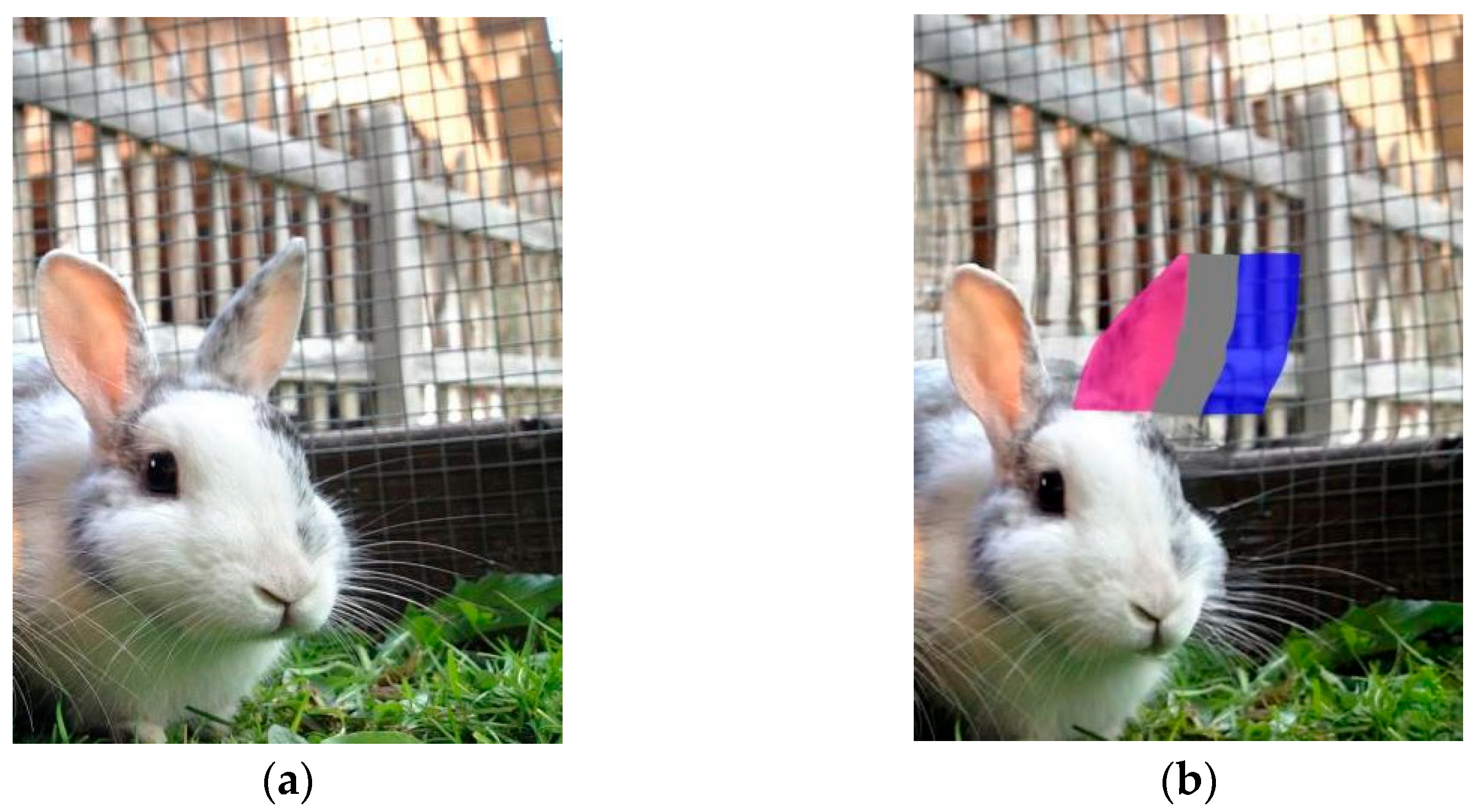
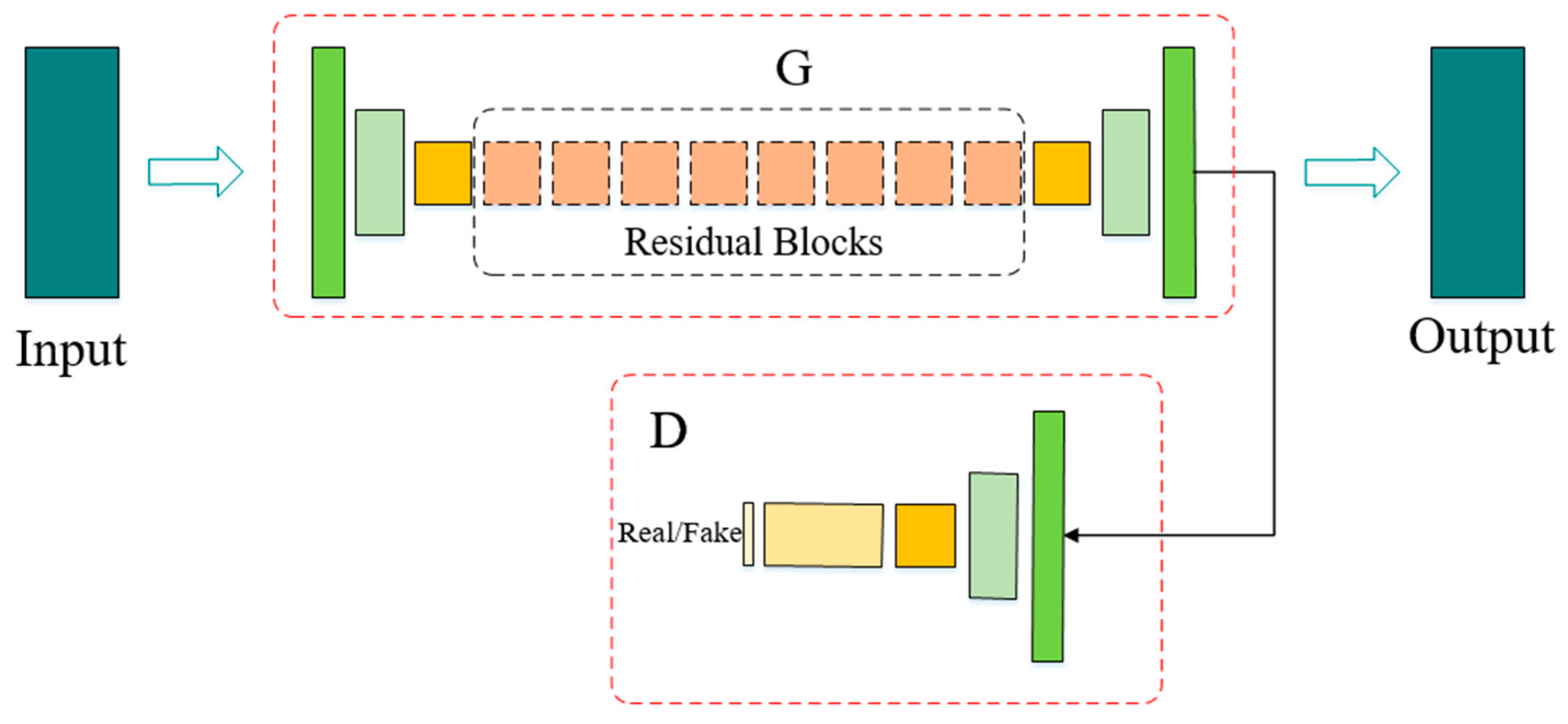
2.3. Layered Depth Image Inpainting

The filling quality of the information of occluded area affects the accuracy of the virtual view to be estimated. People have a strong desire to predict unknown information, so we hope that we can create an explanation for it through some kind of law. For example, the background area still retained the texture details and edge information of the partial visible content in the occluded area.
In the process of the inpainting of the information on the color and depth of the occluded area, the direct application of PConv may lead to problems such as continuous information and slow filling of area information. Therefore, the method adopted in this paper is similar to that in [17,50], that is, the PConv network was mapped to the LDI layer, and the local operator was mapped to the LDI for processing. In this way, it was not necessary to train the inpainting network in the LDI, but directly use the pre-trained weight network for the inpainting of the image in the LDI, so as to update the inpainting depth edge through the stacked PConv and mask.
In the PConv layer of the LDI, the value tensor P (P = C × K, where C is the number of channels and K is the number of LDI pixels) is used to store color information from each layer or activate mapping, and the index tensor I of 6 × K is used to store the pixel coordinates and their neighborhood information ((x, y) and (left, right, top, bottom)). The binary mask tensor M represents the positions of pixels that need inpainting. This allows the valid location to be marked by updating the mask after the PConv operation. The PConv network is implemented by using the U-Net network similar to that in [51], where all fully convolution operations were replaced with PConv operations. In the network, the feature mapping and mask output by the upper layer serve as the input of the feature mapping and mask of the next PConv layer, and the input of the last layer will contain the original image and mask, so that new pixels different from the original content can be generated in the occluded area. By using the inpainting edge information filling method of PConv and mask, the contents of the image edge filling were not affected by other invalid information. In the LDI inpainting network, after five down-samplings in the encoder, the PConv was mapped to the LDI representation through the PConv network mapping mentioned above. Then, the Chameleon search algorithm was used to determine the optimal output channel parameters for each sample in the encoder and decoder to realize the complete inpainting of the image.
Loss function: In order to train the image inpainting model, the loss function of image reconstruction is defined as L r e c , which is composed of pixel loss function L b s , perception loss function L p r e c and flatness loss function L f l a t . The expression is as follows:
L r e c = α L b s + β L p r e c + γ L f l a t
where the parameters are set as α = 1 , β = 8   and   γ = 0.5 .
Pixel loss function L b s consists of background area reconstruction loss function L b and occluded area reconstruction loss function L s :
L b s = L b + L s  
L b = 1 N I t B I o u t I t
L s = 1 N I t S I o u t I t
where I o u t is the output image after inpainting, I t is the ground truth image, N I t is the total number of pixels and B and S are the binary mask of the background area and the occluded area, respectively.
Then, we define perception loss L p r e c proposed by Johnson et al. [52]:
L p r e c = p = 0 P 1 ψ p I o u t ψ p I t N ψ p I t + p = 0 P 1 ψ p I o o u t ψ p I t N ψ p I t
where ψ p I t is the activation mapping of the pth layer selected when the input is I t ; N ψ p I t is the total number of elements in ψ p I t and I o o u t is the original output image, which is composed of pixels in the occluded area and in the background area of the true image. The calculation of L p r e c can be regarded as the activation mappings of I o u t and I o o u t . This kind of mapping operation at the middle layer level of the network can effectively optimize the edge information of the occluded area.
Finally, we define the flatness loss function L f l a t , and the expression is as follows:
L f l a t = ( i , j ) R , ( i , j + 1 ) R I o o u t i , j + 1 I o o u t i , j 1 N I o o u t + ( i , j ) R , ( i + 1 , j ) R I o o u t i + 1 , j I o o u t i , j N I o o u t
where N I o o u t is the number of elements in I o o u t and R is the expansion area of pixels in the occluded area.

2.4. Virtual View Optimization

When the depth information of objects in the scene is relatively complex, the inpainting model can be applied several times for processing until the occluded area is completely processed. In Section 2.3, the color and depth of the occluded area are processed, respectively. In order to further improve the quality of the virtual view, an optimized GAN was added into the inpainting network to establish the connection between color and depth through the regional consistency relationship. As an image understanding method, the semantic segmentation defines a unique label for each pixel in the input image. Semantic segmentation images contain various types of objects whose edges generate depth jumps and whose internal depths are mostly continuous. The spatial geometric relation information of objects in the image can be acquired from depth images. After combining the above features and matching RGB images as the input of the virtual view optimization network, more accurate virtual view images are acquired through the C64-C128-C256-C512 network architecture proposed in [53], where C is the Convolution–BatchNorm–ReLU block, and 64, 128, 256 and 512 are the numbers of filters. In depth estimation, the method adopted in this paper is to acquire the depth image through semantic segmentation, so it can also be used to acquire the input image in the optimization network. The virtual view optimization network framework is shown in Figure 6.
In Figure 6, G d is the depth generator, G c is the color generator, D d is the depth discriminator, D c is the color discriminator and D is the shared discriminator. The color information and the depth information of the image are made consistent by the shared discriminator D . The shared discriminator D receives a set of RGB-D as input, and differentiates the input content, then corresponds to the true RGB-D. The depth generator G d and color generator G c receive feedback from their respective discriminators to achieve optimization. The optimization loss function is defined as L o p t , and the expression is as follows:
L o p t = E x , y log D y c , y d + E x log 1 D G c x c , G d x d
where x c is the color image that has not been optimized, x d is the depth image that has not been optimized, y c is the color image that has been optimized and y d is the depth image that has been optimized. The final optimized color image and depth image are represented by G * c and G * d , respectively, whose expressions are as follows:
G * c = min G c max D R G B + λ min G c max D L o p t + λ L 2 L 2 y c , G c x c
G * d = min G d max D d + λ min G d max D L o p t + λ L 2 L 2 y d , G d x d
where λ = 0.8 and λ L 2 = 80 . L 2 loss is chosen because it is closer to the true output.

3. Results

3.1. Training and Dataset

The inpainting network in this paper includes an edge inpainting network, depth inpainting network and color inpainting network. In the inpainting of the edge, the network structure of [44] was used. The experiment of this paper was carried out in the PyTorch 1.0 framework of the Linux platform, and the network was trained by the MS-COCO dataset [54]. Adam optimizer [55] was used to optimize the model, where β was 0.85. Then, the generator was trained by a Canny edge detector with an initial learning rate of 10 4 until it converged. In the inpainting process of depth information and color information, the ImageNet dataset [56] and Places dataset [57] were used for training and testing. The ImageNet dataset contained 14 million scene photos, including more than 20,000 scenes. We selected 17,811 photos of 40 scenes, among which 12,531 photos were used for training and 5280 photos were used for testing. The Places dataset contained 10 million scene photos, including more than 400 scenes. We selected 25,628 photos of 50 scenes, among which 17,856 photos were used for training and 7772 photos were used for testing. The U-Net frame [50] was used to train the model, and the PConv layers were used to replace the full convolution layers. In the decoding stage, the nearest neighbor interpolation was used, and the skip link was used to take the two groups of feature mapping and mask as the input of the next PConv layer, respectively. Moreover, the input of the final PConv layer contained the related information of the original image, so that the model could replicate the non-hole pixels. The multi-modal pair discriminator was used to optimize the GAN model to further enhance the interdomain consistency of color and depth, the learning rate was set as 2 × 10 4 and batch_size = 6.

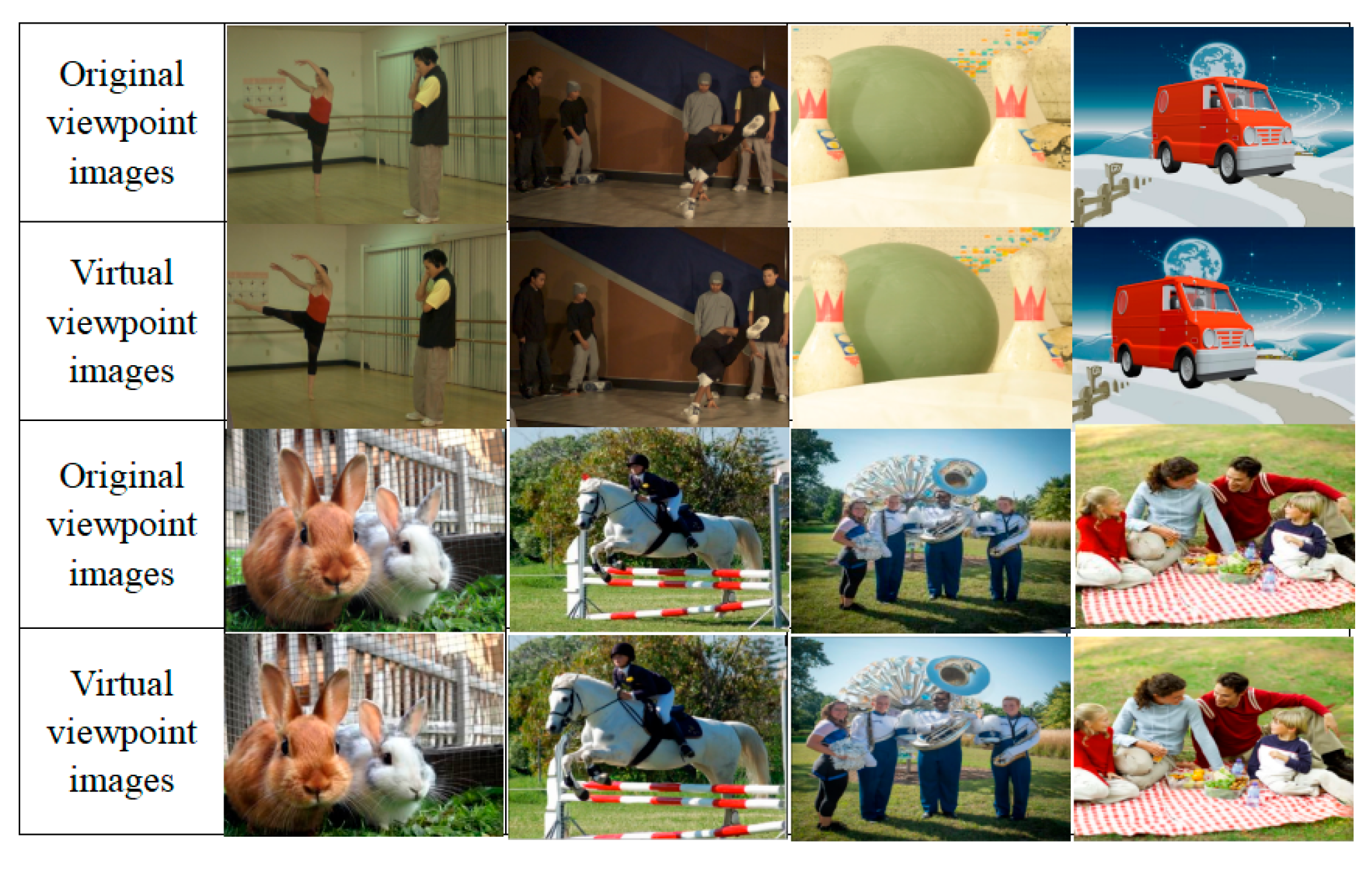
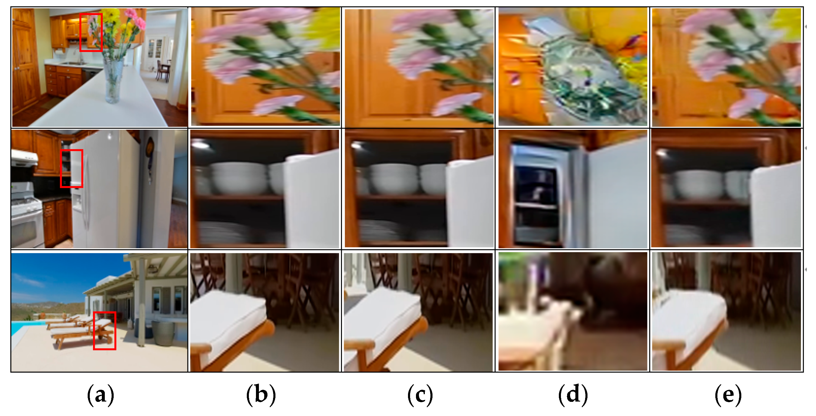
3.2. Comparison of Subjective Quality

In the subjective quality comparison, two comparison methods were used for verification. The first method was to use C4D v.R19 software to establish a standard model, and then regenerate the viewpoint images of the model at different viewpoints. Finally, they were compared with the virtual viewpoint images generated by the method in this paper, as shown in Figure 7. Figure 7a are the standard model images established by C4D, and the position of the model was set as x = 0. Figure 7b,d are the viewpoint images of the model generated by C4D at x = −3 and x = +3, respectively, and Figure 7c,e are the virtual viewpoint images of the model estimated by the method in this paper at x = −3 and x = +3, respectively.
As can be seen from the experimental comparison results in Figure 7, for single RGB images with given viewpoints, the virtual viewpoint images at x = −3 and x = +3 obtained by estimation were of high quality. It can be seen from the contents marked by red boxes in Figure 7b,c that the houses and clouds in the occluded areas had been well extended after a series of “learning”, which also shows that the virtual viewpoint images generated by the model in this paper can make full use of background information and edge information to fill in the invisible occluded area so that the content of the virtual viewpoint image was closer to that of the true viewpoint image.
The second method was to use 3D image sequences ballet and breakdancers provided by Microsoft Research Asia to conduct the experiment. The image sequences contained eight reference viewpoints, and the camera distributions are shown in Figure 8. In this paper, the viewpoint frame image at the position of Cam4 was selected as the input image, and the virtual viewpoint images at the position of Cam3 and Cam5 were estimated, respectively; then, the inpainting results of the algorithm in this paper were compared with the true images at corresponding viewpoints.
In Figure 9 and Figure 10, image sequences of ballet and breakdancers were used, respectively, for the experiment. Figure 9a is the input image, which is the 10th frame taken by Cam4. Figure 9b,c are the 10th frame images taken by Cam3 and Cam5, respectively. Figure 9d,e are the virtual view images of Cam3 and Cam5 generated by the method in this paper, respectively. Figure 10a is the input image, which is the 20th frame taken by Cam4. Figure 10b,c are the 20th frame images taken by Cam3 and Cam5, respectively. Figure 10d,e are the virtual view images of Cam3 and Cam5 generated by the method in this paper, respectively. It can be seen from Figure 9d that the mural on the wall occluded by the ballet dancer was filled with information according to the direction of the texture of the mural after “learning”, and the filled content was very close to the true image. It can be seen from the enlarged images in Figure 9d,e that the experimental results of the method adopted in this paper could well retain and extend the detailed information of each object when filling the occluded area. In Figure 10, the 20th frame image taken by Cam4 was selected as the input image. In Figure 10e, for the information of the wall occluded by the male dancer, contents in different areas were also filled according to the difference in color. It can be seen from the above experimental results that the virtual viewpoint images generated by the method proposed in this paper were not affected by the void problem, and the added optimization network greatly reduced the impact of the artifact problem. This is because the accurate extraction of edge information ensured that more useful information could be relied on when filling the information of the occluded area so as to avoid confusion with useless information.
The method in this paper is widely applicable. We randomly selected eight images with different styles, sizes and resolutions such as people, animals and real objects for virtual viewpoint image rendering from Veer Gallery, Visual China website, Graviti website, Microsoft Research Asia dataset, etc., which all achieved good experimental results. The result is shown in Figure 11.
The experimental results of the proposed method were compared with other state-of-the-art methods in order to achieve a more intuitive feeling of the effect of rendering virtual view images. In the RealEstate10K dataset, three groups of images were randomly selected for experiment. Figure 12a are the input images, and the contents in the red boxes are partially enlarged, as shown in Figure 12b. Figure 12d are the virtual viewpoint images generated by the method of [58]. Figure 12e are the virtual viewpoint images generated by the method proposed in this paper, and Figure 12c are the true images of Figure 12d,e. By observing the experimental results, it can be seen that the virtual viewpoint images rendered by the method in this paper can effectively fill the information of the occluded areas; the detail features of the background areas are well retained and extended and the color information is reasonably filled according to the context. The effective implementation of the above work not only ensures the accuracy of the rendered virtual viewpoint images but also solves the problems of void and artifact.

3.3. Objective Quality Comparison

In order to objectively evaluate the quality of the generated virtual viewpoint images in Figure 12, the Structural Similarity Index (SSIM) and the Peak Signal to Noise Ratio (PSNR) were adopted.
The SSIM measures the similarity between the ground truth image and the virtual viewpoint image from brightness, contrast and structure, respectively. Its value range is [0, 1], and the larger the value is, the smaller the image distortion is. The expression is as follows:
S S I M ( X , Y ) = l ( X , Y ) × c ( X , Y ) × s ( X , Y )
where X is the virtual viewpoint image, Y is the ground truth image. l X , Y , c X , Y and s X , Y are the brightness similarity, contrast similarity and structure similarity of the image, respectively, and the expressions are as follows:
l ( X , Y ) = 2 μ X μ Y + C 1 μ X 2 + μ Y 2 + C 1
c ( X , Y ) = 2 σ X σ Y + C 2 σ X 2 + σ Y 2 + C 2
s ( X , Y ) = σ X Y + C 3 σ X σ Y + C 3
where μ X and μ Y are the mean value of X and Y, respectively, σ X and σ Y are the variances of X and Y, respectively, and σ X σ Y are the covariances of X and Y.
The PSNR is the inter-pixel error, and the larger the value is, the smaller the image distortion is. The expression is as follows:
P S N R = 10 log 10 ( 2 n 1 ) 2 M S E
where n is the number of bits per pixel, which is generally set as 8; H and W are the height and width of the image, respectively; MSE is the mean square error of virtual view image X and ground truth image Y, and the expression is as follows:
M S E = 1 H × W i = 1 H j = 1 W ( X ( i , j ) Y ( i , j ) ) 2
The SSIM values and PSNR values of true images and virtual viewpoint images generated by different methods in Figure 12 are calculated, respectively, as shown in Table 1. It can be seen from the values in Table 1 that the virtual viewpoint images rendered by the method in this paper are of high similarity and with small inter-pixel error.
To prove that the proposed method can be used to generate high-quality virtual view images and is suitable for various scenarios, 3D image sequences of ballet and breakdancers provided by Microsoft Research Asia were used to evaluate the proposed method. In the experiment, the proposed method was compared with other excellent methods, and the Root Mean Squared Error (RMSE), SSIM and PSNR were selected as evaluation indexes. The results are shown in Table 2 and Table 3.
As can be seen from Table 2 and Table 3, the performance of the proposed method in the three evaluation indexes was outstanding. The error was lower than other algorithms, and the accuracy was higher than most other algorithms. In [7], the binocular view image was used to generate the virtual view image, and the occluded area was inpainted by the fusion of left and right view images. However, there was uneven brightness during the implementation, and the input image correction was required to improve the quality of the output image. In contrast, the method proposed in this paper only needs a single image, and it has low requirements on the image content, so it has better generalization ability. Ref. Rombach et al. [58] adopted a deep learning-based method similar to that in this paper for virtual view image estimation, but it can be seen from the evaluation indexes that the proposed method has better expressiveness. To make a more objective evaluation, the evaluation indexes of the other methods used in the experiment were averaged first, and then the evaluation indexes of the method proposed in this paper were compared with those of the other methods. For the image sequences of the ballet and breakdancers, it can be seen that the RMSE of the proposed method was 35.5% and 24.3% lower than the average value, the SSIM of the proposed method was 5.28% and 6.76% higher than the average value, and the PSNR of the proposed method was 10.1% and 12% higher than the average value. These data show that the proposed method can significantly improve the quality of the virtual view image.

4. Discussion

Virtual view image acquisition is the key technology in the field of 3D display. Fast and accurate access to high-quality virtual view images is conducive to the promotion of 3D display technology in the fields of smart medicine, autonomous driving, and intelligent machine manufacturing. In the existing technologies, the geometric object information among multi-view images can be used for virtual view image acquisition, but this method is usually limited by the acquisition cost of time and economic factors, including the complex hardware structure of the acquisition system, a large amount of acquisition view images, correction of the acquisition camera and accuracy of the acquisition image. When the monocular image is used for virtual view image acquisition, since the monocular image only contains less 3D object information, the acquired base line of virtual view image is small, the edge of object in the synthesized image is very fuzzy and there are some voids. Therefore, to acquire high-quality virtual view images, it is urgent to solve the above problems.
In the existing methods of virtual view image acquisition through multi-view images, the geometric object information among multi-view images or the dense camera array are usually used for acquisition, but the images need to be corrected before virtual view image estimation, which increases the implementation cost. At the same time, artifacts and voids appear easily. When a CNN is used to acquire virtual view image, depth information is mostly needed, but the depth information acquired by the CNN is not accurate enough, which affects the quality of virtual view image. The quality is improved when a GAN is used to acquire a virtual view image. However, the use of a full convolutional network decreases the network’s efficiency, which is unfavorable to the promotion of 3D display technology. At the same time, limited by the amount of experimental data, most network models have poor generalization ability. Therefore, a GAN was adopted as the basic network framework of virtual view image estimation in this paper.
To increase the quality of the virtual view image, we propose a virtual view acquisition technique for complex scenes in monocular images based on layered depth image. The multilayer representation of the LDI is used to group the depth discontinuities at the edge of the occluded area reasonably. The edge inpainting network is combined with the inpainting network of color and depth to fill the information of color and depth in the occluded area to generate the virtual viewpoint image. Then, a GAN is used to optimize the color and depth to further improve the quality of the generated virtual viewpoint image. The experimental results show that compared with other advanced virtual view methods, the proposed method has very good expressiveness and generalization ability.

5. Conclusions

To improve the quality of the acquired virtual view image, a virtual view acquisition technique for complex scenes of monocular images based on layered depth images is proposed in this paper. Firstly, the multilayer representation of the LDI is introduced, and the depth discontinuities of the edge of the occluded area are reasonably grouped, so as to determine the edge of the occluded area and inpaint the edge through the GAN. It is prepared for the information filling of the occluded area. Then, the information of color and depth in the occluded area is filled through the PConv network. Since the position information of the inpainted edge has been determined, the network efficiency is improved. Finally, the semantic segmentation information is added to the color inpainting network and the deep inpainting network, and Convolution–BatchNorm–ReLU blocks are adopted in the shared discriminator to optimize the virtual view. The results of the experiments show that in the 3D image sequences of the ballet and breakdancers provided by Microsoft Research Asia, the RMSE of the proposed method is 35.5% and 24.3% lower than the average value, the SSIM of the proposed method is 5.28% and 6.76% higher than the average value, and the PSNR of the proposed method is 10.1% and 12% higher than the average value. At the same time, the limit offset of the virtual view acquired by the monocular image is measured several times. Although the complexity and depth of the information contained in the images are different, the virtual view images estimated by the method proposed in this paper can be clearly viewed at the angle range of −30° to 30° when the three-dimensional display is carried out. These results prove the superiority of the algorithm proposed in this paper. In terms of practical application, the method proposed in this paper can be applied to 3D movies, VR and smart medical technology so as to improve the three-dimensional expression ability and enable users to have a better visual experience. However, the method proposed in this paper also has some defects. To improve the quality of the virtual view image, the network structure adopted in this paper is relatively complex, and the computation is large. Therefore, to apply it to terminal devices such as mobile phones and tablet computers, the model in this paper will be lightweight in the future, so as to realize the comprehensive promotion of 3D display technology.

Author Contributions

Conceptualization, Q.W. and Y.P.; methodology, Q.W.; software, Q.W.; validation, Q.W.; writing—original draft, Q.W.; writing—review and editing, Q.W.; resources, Y.P.; project administration, Y.P.; funding acquisition, Y.P. All authors have read and agreed to the published version of the manuscript.

Funding

This research was funded by the Project of the Jilin Provincial Science and Technology Department, grant number 20220201062GX.

Institutional Review Board Statement

Not applicable.

Informed Consent Statement

Not applicable.

Data Availability Statement

The original contributions presented in the study are included in the article; further inquiries can be directed to the corresponding author.

Conflicts of Interest

The authors declare no conflicts of interest.

References

  1. Yu, X.; Sang, X.; Xing, S.; Zhao, T.; Chen, D.; Cai, Y.; Yan, B.; Wang, K.; Yuan, J.; Yu, C.; et al. Natural three-dimensional display with smooth motion parallax using active partially pixelated masks. Opt. Commun. 2014, 313, 146–151. [Google Scholar] [CrossRef]
  2. Debevec, P.; Taylor, C.; Malik, J. Modeling and rendering architecture from photographs: A hybrid geometry and image-based approach. In Proceedings of the 23rd Annual Conference on Computer Graphics and Interactive Techniques, New Orleans, LA, USA, 4–9 August 1996; pp. 11–20. [Google Scholar]
  3. Gortler, S.; Grzeszczuk, R.; Szeliski, R.; Co-Hen, M. The lumigraph. In Proceedings of the 23rd Annual Conference on Computer Graphics and Interactive Techniques, New Orleans, LA, USA, 4–9 August 1996; pp. 43–54. [Google Scholar]
  4. Levoy, M.; Hanrahan, P. Light field rendering. In Proceedings of the 23rd Annual Conference on Computer Graphics and Interactive Techniques, New Orleans, LA, USA, 4–9 August 1996; pp. 31–42. [Google Scholar]
  5. Zhang, Q.; Li, S.; Guo, W.; Chen, J.; Wang, B.; Wang, P.; Huang, J. High quality virtual view synthesis method based on geometrical model. Video Eng. 2016, 40, 22–25. [Google Scholar]
  6. Cai, L.; Li, X.; Tian, X. Virtual viewpoint image post-processing method using background information. J. Chin. Comput. Syst. 2022, 43, 1178–1184. [Google Scholar]
  7. Chen, L.; Chen, S.; Ceng, K.; Zhu, W. High image quality virtual viewpoint rendering method and its GPU acceleration. J. Chin. Comput. Syst. 2020, 41, 2212–2218. [Google Scholar]
  8. Zhou, T.; Tucker, R.; Flynn, J.; Fyffe, G.; Snavely, N. Stereo magnifification: Learning view synthesis using multiplane images. ACM Trans. Graph. 2018, 37, 1–12. [Google Scholar]
  9. Tucker, R.; Snavely, N. Single-view view synthesis with multiplane images. In Proceedings of the IEEE/CVF Conference on Computer Vision and Pattern Recognition (CVPR), Seattle, WA, USA, 13–19 June 2020; pp. 548–557. [Google Scholar]
  10. Dosovitskiy, A.; Springenberg, J.; Tatarchenko, M.; Brox, T. Learning to generate chairs, tables and cars with convolutional networks. IEEE Trans. Pattern Anal. Mach. Intell. 2017, 39, 692–705. [Google Scholar] [CrossRef]
  11. Yang, J.; Reed, S.; Yang, M.; Lee, H. Weakly-supervised disentangling with recurrent transformations for 3d view synthesis. In Proceedings of the 29th Annual Conference on Neural Information Processing Systems (NIPS), Montreal, QC, Canada, 7–12 December 2015; pp. 1099–1107. [Google Scholar]
  12. Tatarchenko, M.; Dosovitskiy, A.; Brox, T. Multi-view 3D models from single images with a convolutional network. In Proceedings of the 14th European Conference on Computer Vision (ECCV), Amsterdam, The Netherlands, 8–16 October 2016; pp. 322–337. [Google Scholar]
  13. Schonberger, J.; Zheng, E.; Frahm, J.; Pollefeys, M. Pixelwise view selection for unstructured multiview stereo. In Proceedings of the 14th European Conference on Computer Vision (ECCV), Amsterdam, The Netherlands, 8–16 October 2016; pp. 501–518. [Google Scholar]
  14. Zeng, Q.; Chen, W.; Wang, H.; Tu, C.; Cohen-Or, D.; Lischinski, D.; Chen, B. Hallucinating stereoscopy from a single image. In Proceedings of the 36th Annual Conference of the European-Association-for-Computer-Graphics, Zurich, Switzerland, 4–8 May 2015; pp. 1–12. [Google Scholar]
  15. Liang, H.; Chen, X.; Xu, H.; Ren, S.; Wang, Y.; Cai, H. Virtual view rendering based on depth map preprocessing and image inpainting. J. Comput. Aided Des. Comput. Graph. 2019, 31, 1278–1285. [Google Scholar] [CrossRef]
  16. Dhamo, H.; Tateno, K.; Laina, I.; Navab, N.; Tombari, F. Peeking behind objects: Layered depth prediction from a single image. Pattern Recognit. Lett. 2019, 125, 333–340. [Google Scholar] [CrossRef]
  17. Kopf, J.; Matzen, K.; Alsisan, S.; Quigley, O.; Ge, F.; Chong, Y.; Patterson, J.; Frahm, J.; Wu, S.; Yu, M. One shot 3d photography. ACM Trans. Graph. 2020, 39, 1–13. [Google Scholar] [CrossRef]
  18. Godard, C.; Mac Aodha, O.; Firman, M.; Brostow, G. Digging into self-supervised monocular depth estimation. In Proceedings of the IEEE/CVF International Conference on Computer Vision (ICCV), Seoul, Republic of Korea, 27 October–2 November 2019; pp. 3827–3837. [Google Scholar]
  19. Zhou, T.; Brown, M.; Snavely, N.; Lowe, D. Unsupervised learning of depth and ego-motion from video. In Proceedings of the 30th IEEE/CVF Conference on Computer Vision and Pattern Recognition (CVPR), Honolulu, HI, USA, 21–26 July 2017; pp. 6612–6619. [Google Scholar]
  20. Mildenhall, B.; Srinivasan, P.; Ortiz-Cayon, R.; Kalantari, N.; Ramamoorthi, R.; Ng, R.; Kar, A. Local light fifield fusion: Practical view synthesis with prescriptive sampling guidelines. ACM Trans. Graph. 2019, 38, 1–14. [Google Scholar] [CrossRef]
  21. Niklaus, S.; Mai, L.; Yang, J.; Liu, F. 3D Ken Burns effect from a single image. ACM Trans. Graph. 2019, 38, 184. [Google Scholar] [CrossRef]
  22. Penner, E.; Zhang, L. Soft 3D reconstruction for view synthesis. ACM Trans. Graph. 2017, 36, 1–11. [Google Scholar] [CrossRef]
  23. Porter, T.; Duff, T. Compositing digital images. ACM Siggraph Comput. Graph. 1984, 18, 253–259. [Google Scholar] [CrossRef]
  24. Scharstein, D.; Szeliski, R. A taxonomy and evaluation of dense two-frame stereo correspondence algorithms. Int. J. Comput. Vis. 2002, 47, 7–42. [Google Scholar] [CrossRef]
  25. Szeliski, R.; Golland, P. Stereo matching with transparency and matting. Int. J. Comput. Vis. 1999, 32, 45–61. [Google Scholar] [CrossRef]
  26. Roy, A.; Todorovic, S. Monocular depth estimation using neural regression forest. In Proceedings of the 2016 IEEE Conference on Computer Vision and Pattern Recognition (CVPR), Seattle, WA, USA, 27–30 June 2016; pp. 5506–5514. [Google Scholar]
  27. Saxena, A.; Chung, S.; Ng, A. Learning depth from single monocular images. In Proceedings of the 18th International Conference on Neural Information Processing Systems, Vancouver, BC, Canada, 4–7 December 2006; pp. 1161–1168. [Google Scholar]
  28. Liu, B.; Gould, S.; Koller, D. Single image depth estimation from predicted semantic labels. In Proceedings of the 23rd IEEE Conference on Computer Vision and Pattern Recognition (CVPR), San Francisco, CA, USA, 13–18 June 2010; pp. 1253–1260. [Google Scholar]
  29. Jiao, J.; Cao, Y.; Song, Y.; Lau, R. Look deeper into depth: Monocular depth estimation with semantic booster and attention-driven loss. In Proceedings of the 15th European Conference on Computer Vision (ECCV), Munich, Germany, 8–14 September 2018; pp. 55–71. [Google Scholar]
  30. Song, S.; Yu, F.; Zeng, A.; Chang, A.; Savva, M.; Funkhouser, T. Semantic scene completion from a single depth image. In Proceedings of the 30th IEEE/CVF Conference on Computer Vision and Pattern Recognition (CVPR), Honolulu, HI, USA, 21–26 July 2017; pp. 190–198. [Google Scholar]
  31. Ranftl, R.; Lasinger, K.; Hafner, D.; Schindler, K.; Koltun, V. Towards robust monocular depth estimation: Mixing datasets for zero-shot cross-dataset transfer. IEEE Trans. Pattern Anal. Mach. Intell. 2022, 44, 1623–1637. [Google Scholar] [CrossRef]
  32. Shade, J.; Gortler, S.; He, L.; Szeliski, R. Layered depth images. In Proceedings of the 25th Annual Conference on Computer Graphics and Interactive Techniques, Orlando, FL, USA, 19–24 July 1998; pp. 231–242. [Google Scholar]
  33. Hedman, P.; Alsisan, S.; Szeliski, R.; Kopf, J. Casual 3D Photography. ACM Trans. Graph. 2017, 36, 1–15. [Google Scholar] [CrossRef]
  34. Hedman, P.; Kopf, J. Instant 3D Photography. ACM Trans. Graph. 2018, 37, 1–12. [Google Scholar] [CrossRef]
  35. Tulsiani, S.; Tucker, R.; Snavely, N. Layer-structured 3d scene inference via view synthesis. In Proceedings of the 15th European Conference on Computer Vision (ECCV), Munich, Germany, 8–14 September 2018; pp. 311–327. [Google Scholar]
  36. Garcia-Mateos, G.; Hernandez-Hernandez, J.; Escarabajal-Henarejos, D.; Jaen-Terrones, S.; Molina-Martinez, J. Study and comparison of color models for automatic image analysis in irrigation management applications. Agric. Water Manag. 2015, 151, 158–166. [Google Scholar] [CrossRef]
  37. Hernandez-Hernandez, J.; Garcia-Mateos, G.; Gonzalez-Esquiva, J.; Escarabajal-Henarejos, D.; Ruiz-Canales, A.; Molina-Martinez, J. Optimal color space selection method for plant/soil segmentation in agriculture. Comput. Electron. Agric. 2016, 122, 124–132. [Google Scholar] [CrossRef]
  38. Khot, T.; Agrawal, S.; Tulsiani, S.; Mertz, C.; Lucey, S.; Hebert, M. Learning unsupervised multi-view stereopsis via robust photometric consistency. In Proceedings of the 32nd IEEE/CVF Conference on Computer Vision and Pattern Recognition (CVPR), Long Beach, CA, USA, 16–20 June 2019. [Google Scholar]
  39. Ronneberger, O.; Fischer, P.; Brox, T. U-net: Convolutional networks for biomedical image segmentation. In Proceedings of the 18th International Conference on Medical Image Computing and Computer-Assisted Intervention (MICCAI), Munich, Germany, 5–9 October 2015; pp. 234–241. [Google Scholar]
  40. Simonyan, K.; Zisserman, A. Very deep convolutional networks for large-scale image recognition. In Proceedings of the 3th International Conference on Learning Representations, San Diego, CA, USA, 7–9 May 2015. [Google Scholar]
  41. Dosovitskiy, A.; Beyer, L.; Kolesnikov, A.; Weissenborn, D.; Zhai, X.; Unterthiner, T.; Dehghani, M.; Minderer, M.; Heigold, G.; Gelly, S.; et al. An imageis worth 16x16 words: Transformers for image recognition at scale. In Proceedings of the IEEE/CVF Conference on Computer Vision and Pattern Recognition (CVPR), Nashville, TN, USA, 19–25 June 2019. [Google Scholar]
  42. Ren, J.; Xu, L.; Yan, Q.; Sun, W. Shepard convolutional neural networks. In Proceedings of the 29th Annual Conference on Neural Information Processing Systems (NIPS), Montreal, QC, Canada, 7–12 December 2015; pp. 901–909. [Google Scholar]
  43. Goodfellow, I.; Pouget-Abadie, J.; Mirza, M.; Xu, B.; Warde-Farley, D.; Ozair, S.; Courville, A.; Bengio, Y. Generative Adversarial Networks. Commun. ACM 2020, 63, 139–144. [Google Scholar] [CrossRef]
  44. Nazeri, K.; Ng, E.; Joseph, T.; Qureshi, F.; Ebrahimi, M. Edgeconnect: Generative image inpainting with adversarial edge learning. In Proceedings of the IEEE/CVF Conference on Computer Vision and Pattern Recognition, Long Beach, CA, USA, 16–20 June 2019; pp. 1–17. [Google Scholar]
  45. Xiong, W.; Yu, J.; Lin, Z.; Yang, J.; Lu, X.; Barnes, C.; Luo, J. Foreground-aware image inpainting. In Proceedings of the 32nd IEEE/CVF Conference on Computer Vision and Pattern Recognition (CVPR), Long Beach, CA, USA, 16–20 June 2019; pp. 5833–5841. [Google Scholar]
  46. Ren, Y.; Yu, X.; Zhang, R.; Li, T.; Liu, S.; Li, G. Structureflow: Image inpainting via structure-aware appearance flow. In Proceedings of the IEEE/CVF International Conference on Computer Vision (ICCV), Seoul, Republic of Korea, 27 October–2 November 2019; pp. 181–190. [Google Scholar]
  47. Shih, M.; Su, S.; Kopf, J.; Huang, J. 3D photography using context-aware layered depth inpainting. In Proceedings of the IEEE/CVF Conference on Computer Vision and Pattern Recognition (CVPR), Seattle, WA, USA, 13–19 June 2020; pp. 8025–8035. [Google Scholar]
  48. He, K.; Zhang, X.; Ren, S.; Sun, J. Deep residual learning for image recognition. In Proceedings of the 2016 IEEE Conference on Computer Vision and Pattern Recognition (CVPR), Seattle, WA, USA, 27–30 June 2016; pp. 770–778. [Google Scholar]
  49. Goodfellow, I.; Pouget-Abadie, J.; Mirza, M.; Xu, B.; Warde-Farley, D.; Ozair, S.; Courville, A.; Bengio, Y. Generative adversarial nets. In Proceedings of the 28th Conference on Neural Information Processing Systems (NIPS), Montreal, QC, Canada, 8–13 December 2014; pp. 2672–2680. [Google Scholar]
  50. Liu, G.; Reda, F.; Shih, K.; Wang, T.; Tao, A.; Catanzaro, B. Image inpainting for irregular holes using partial convolutions. In Proceedings of the 15th European Conference on Computer Vision (ECCV), Munich, Germany, 8–14 September 2018; pp. 89–105. [Google Scholar]
  51. Eslami, S.; Rezende, D.; Besse, F.; Viola, F.; Morcos, A.; Garnelo, M.; Ruderman, A.; Rusu, A.; Danihelka, I.; Gregor, K. Neural scene representation and rendering. Science 2018, 360, 1204–1210. [Google Scholar] [CrossRef] [PubMed]
  52. Johnson, J.; Alahi, A.; Li, F. Perceptual losses for real-time style transfer and super-resolution. In Proceedings of the 14th European Conference on Computer Vision (ECCV), Amsterdam, The Netherlands, 8–16 October 2016; pp. 694–711. [Google Scholar]
  53. Isola, P.; Zhu, J.; Zhou, T.; Efros, A. Image-to-image translation with conditional adversarial networks. In Proceedings of the 30th IEEE/CVF Conference on Computer Vision and Pattern Recognition (CVPR), Honolulu, HI, USA, 21–26 July 2017; pp. 5967–5976. [Google Scholar]
  54. Lin, T.; Maire, M.; Belongie, S.; Hays, J.; Perona, P.; Ramanan, D.; Dollar, P.; Zitnick, C. Microsoft coco: Common objects in context. In Proceedings of the 13th European Conference on Computer Vision (ECCV), Zurich, Switzerland, 6–12 September 2014; pp. 740–755. [Google Scholar]
  55. Kingma, D.; Ba, J. Adam: A method for stochastic optimization. In Proceedings of the 3rd International Conference for Learning Representations, San Diego, CA, USA, 7–9 May 2015; pp. 1–15. [Google Scholar]
  56. Russakovsky, O.; Deng, J.; Su, H.; Krause, J.; Satheesh, S.; Ma, S.; Huang, Z.; Karpathy, A.; Khosla, A.; Bernstein, M. ImageNet Large Scale Visual Recognition Challenge. Int. J. Comput. Vis. 2015, 115, 211–252. [Google Scholar] [CrossRef]
  57. Zhou, B.; Lapedriza, A.; Khosla, A.; Oliva, A.; Torralba, A. Places: A 10 million image database for scene recognition. IEEE Trans. Pattern Anal. Mach. Intell. 2018, 40, 1452–1464. [Google Scholar] [CrossRef]
  58. Rombach, R.; Esser, P.; Ommer, B. Geometry-free view synthesis: Transformers and no 3D priors. In Proceedings of the 18th IEEE/CVF International Conference on Computer Vision (ICCV), Montreal, BC, Canada, 11–17 October 2021; pp. 14336–14346. [Google Scholar]
Figure 1. The overall frame of virtual viewpoint image generation.
Applsci 14 10557 g001
Figure 2. Depth images of various types generated by the method proposed in this paper.
Applsci 14 10557 g002
Figure 3. Depth image preprocessing. (a) The input RGB image. (b) Depth image after filtering. (c) The enlarged image of the red box area in (b); (d) The preprocessed image of (c). (e) The image of lines with discontinuous depth.
Applsci 14 10557 g003
Figure 4. The area division of the input RGB image. (a) The input RBG image. (b) Generated virtual view image without inpainting. The pink area is the foreground area, the gray area is the occluded area, and the blue area is the background area.
Applsci 14 10557 g004
Figure 5. The framework of the edge inpainting network.
Applsci 14 10557 g005
Figure 6. The framework of virtual view optimization network.
Applsci 14 10557 g006
Figure 7. Virtual viewpoint images generated at different positions. (a) The images of the standard model established by C4D, and the model position is x = 0; (b) Viewpoint images of the model generated by C4D at x = −3; (c) The virtual viewpoint images of the model estimated by the method in this paper at x = −3; (d) Viewpoint images of the model generated by C4D at x = +3; (e) Virtual viewpoint images of the model estimated by the method in this paper at x = +3.
Applsci 14 10557 g007
Figure 8. Camera distributions.
Applsci 14 10557 g008
Figure 9. Generated virtual viewpoint images using the ballet image sequence. (a) The input image, which is the 10th frame taken by Cam4. (b) The 10th frame image taken by Cam3. (c) The 10th frame image taken by Cam5. (d) The 10th frame image of Cam3, which is generated by the method in this paper. (e) The 10th frame image of Cam5, which is generated by the method in this paper.
Applsci 14 10557 g009
Figure 10. Generated virtual viewpoint images using the breakdancers image sequence. (a) The input image, which is the 20th frame taken by Cam4. (b) The 20th frame image taken by Cam3. (c) The 20th frame image taken by Cam5. (d) The 20th frame image of Cam3, which is generated by the method in this paper. (e) The 20th frame image of Cam5, which is generated by the method in this paper.
Applsci 14 10557 g010
Figure 11. Different types of virtual viewpoint images rendered by the method in this paper.
Applsci 14 10557 g011
Figure 12. Rendered virtual viewpoint images. (a) Input images; (b) The partial enlarged images of the contents in red boxes in (a); (c) The true images of virtual viewpoint images (d,e); (d) Virtual viewpoint images generated by the method of [58]; (e) Virtual viewpoint images generated by the method in this paper.
Applsci 14 10557 g012
Table 1. SSIM and PSNR of true images and virtual viewpoint images generated by different methods.
Virtual Viewpoint ImagesMethodSSIMPSNR
Image1[58]0.831926.54
Ours0.874230.45
Image2[58]0.851727.10
Ours0.893330.79
Image3[58]0.837826.85
Ours0.882529.87
Table 2. Virtual view image performance on ballet dancers.
BalletRMSESSIMPSNR
[7]1.2380.795825.98
[15]1.1650.832827.03
[58]0.7120.894230.85
Our0.6830.893731.12
Table 3. Virtual view image performance on breakdancers.
BreakdancersRMSESSIMPSNR
[7]1.1030.732623.98
[15]1.0850.759625.69
[58]0.8010.832530.81
Our0.7540.842530.53
Disclaimer/Publisher’s Note: The statements, opinions and data contained in all publications are solely those of the individual author(s) and contributor(s) and not of MDPI and/or the editor(s). MDPI and/or the editor(s) disclaim responsibility for any injury to people or property resulting from any ideas, methods, instructions or products referred to in the content.

