Article

High-Fidelity OC-Seislet Stacking Method for Low-SNR Seismic Data

1
College of Geo-Exploration Science and Technology, Jilin University, Changchun 130026, China
2
Research Institute of Geophysical Prospecting, Jilin Oilfield Company, CNPC, Songyuan 138000, China
*
Author to whom correspondence should be addressed.
Appl. Sci. 2024, 14(21), 9973; https://doi.org/10.3390/app14219973
Submission received: 29 September 2024 / Revised: 26 October 2024 / Accepted: 29 October 2024 / Published: 31 October 2024

Abstract

:
Seismic stacking is a core technique in seismic data processing, aimed at enhancing the signal-to-noise ratio (SNR) of data by utilizing seismic data acquisition with multifold geometry. Traditional stacking methods always have certain limitations, such as the reliance on the accuracy of velocity analysis for dip moveout (DMO) in common midpoint (CMP) stacking. The seislet transform, a compression technique tailored to nonstationary seismic data, can compress and stack along the prediction direction of seismic data, which provides a new technical idea for high-fidelity seismic imaging based on the effectiveness of the compression. This paper introduces a high-order OC-seislet stacking method for low-SNR seismic data, capable of achieving the high-fidelity stacking of reflection and diffraction waves simultaneously. With the multi-scale analysis advantages of the seislet transform, this method addresses the dependency of DMO stacking on velocity analysis accuracy. In the frequency–wavenumber–scale domain, the correction compensation of the high-order CDF 9/7 basis function is used to obtain the compression coefficients of the high-order OC-seislet transform. This approach simultaneously stacks frequency–wavenumber information of reflection and diffraction waves with high fidelity while implementing DMO processing. After normalizing the weighting coefficients and applying soft thresholding for denoising, the final result is transformed back to the original time–space domain, yielding high-fidelity stacking sections. The results of applying this method to both synthetic and field data show that, compared with conventional DMO stacking methods, the high-order OC-seislet stacking technique reasonably represents dipping layers and fault amplitudes, and it can achieve a balance of a high SNR and high fidelity in stacked profiles.

1. Introduction

Random noise is one of the most common types of interference in seismic data; in complex media areas such as the piedmont zone, high–steep structures, and volcanic rock cap layers, there is often a significant loss of energy in the effective reflection information [1]. The task of enhancing weak seismic signals becomes increasingly important, because random noise interference often hinders the accurate delineation of deep-target oil and gas zones during onshore and offshore exploration. The classic horizontal stacking technique leverages the advantages of multiple coverage geometry in seismic exploration [2], playing a crucial role in enhancing the SNR of seismic data. Although numerous methods for suppressing random noise in pre-stack data have been developed by many researchers, seismic data stacking remains the most stable and effective high-SNR processing technique in the industry. Since the horizontal stacking method is based on a horizontal layering model, it is essential to perform normal moveout (NMO) before stacking to eliminate the normal time differences at various offset positions of the traces [2]. However, relying solely on time difference moveout is insufficient, as stacking results can be inaccurate in the presence of dipping layers [3]: On the one hand, the CMP gathers after NMO do not correspond to the data recorded from the same reflection point, so the stack cannot reflect the true zero-offset profile. On the other hand, the stacking process based on NMO enhances reflections with specific moveout velocities, while attenuating wave propagation events with different moveout velocities (such as multiple reflections), so this leads to the enhancement of reflection layers with specific slopes during the NMO stacking process, while reflections and diffraction with different slopes, such as those at layer breaks, are attenuated [3]. This phenomenon is particularly pronounced in low-SNR data. Since 1978, DMO has been employed in seismic data processing and has significantly improved the imaging accuracy of seismic data [4]. DMO technology can shift the NMOed data to the zero-offset position, thereby reducing the mutual attenuation effects of wavefields with different reflection slopes.
DMO, also known as partial pre-stack migration, is often one of the most overlooked steps in time-domain imaging, yet it provides more accurate stacking velocities [5]. DMO processing is essential before post-stack migration imaging, as it significantly improves the imaging quality of stacked profiles in complex geological structures. Compared to pre-stack migration, which demands a high accuracy in velocity modeling and considerable computational resources, DMO offers a practical compromise between cost and precision and has achieved widespread application in the industry. Many researchers have proposed different DMO processing methods to achieve accurate imaging. For instance, Yilmaz and Claerbout [6] introduced a finite-difference DMO method [7,8,9,10,11] in common-offset seismic gathers. This method uses a high-order approximations of the wave equation, offering mature theoretical and practical applications, along with advantages in denoising. However, finite-difference methods require calculations at equally spaced intervals and often struggle to accurately represent large offsets and steep reflector dips [7,9,10], even in constant velocity scenarios. Bolondi et al. [12] were the first to suggest extending the concept of offset continuation (OC) and DMO using partial differential equations, describing them as continuous wavefield propagation processes. Bagaini and Spagnolini [13] proposed representing migration continuation with a complete set of pre-stack continuation operators. Hale [14] later defined DMO as an continuation to zero offset, but the limitation of the continuation theory lies in its use of many approximations, which leads to distortions in the impulse response compared to the true elliptical DMO impulse response [15]. Based on the kinematic theory of reflection waves, Hale [3] proposed the Fourier DMO method in the frequency–wavenumber domain from a geometric perspective [16]. This method is theoretically accurate and serves as a benchmark for evaluating the precision of other DMO methods. But it requires numerical integration, which is computationally intensive, and its theory does not effectively illuminate amplitude and phase issues. Some researchers [14,17], based on Deregowski and Rocca’s theory [15], have analyzed the time-domain impulse response of the DMO operator and developed various Kirchhoff integral DMO algorithms. These algorithms are based on the integral formulation and have been found to have the drawback of causing interface distortions. However, their advantage lies in not requiring regular sampling. For three-dimensional data acquisition with significant variations in source–receiver distance and azimuth, integral methods are often the most practical for DMO calculations. Wang [18] proposed a Radon-domain dip moveout (Radon DMO) processing technique. The Radon DMO operator directly maps NMOed data to the Radon domain DMO wavefield. The forward transform converts a single NMO trace into multiple traces distributed along hyperbolas in the Radon domain. Applying the inverse linear Radon transform to produce DMO images results in a good frequency and amplitude preservation. DMO can also be performed in the shot domain, Biondi and Ronen [19] designed a shot gather DMO method equivalent to Hale’s common-offset gather DMO, with this operator being equivalent to the one proposed by Bolondi et al. In more general situations, such as non-linear observation systems [20,21,22] and anisotropic media [23,24,25], various DMO methods have been developed to meet specific processing requirements.
Each of these DMO methods has its own range of applicability and associated advantages and disadvantages. Meanwhile, most DMO stacking methods remain fixed and require the use of L2 norm optimization mathematical theory to scan stacking velocities and implement NMO. The approach of obtaining stacking results based on average amplitude energy has a limited fidelity for diffraction waves. Thus, research into high-fidelity stacking methods for seismic data holds significant industrial value. In terms of algorithm improvements, many scholars [26,27] have developed efficient DMO algorithms using the logarithmic time-stretching transform method originally proposed by Bolondi et al. [12]. The computational efficiency of the "logarithmic stretching" technique is approximately two orders of magnitude higher than Hale’s DMO. For the accurate calculation of the DMO operator, Fomel [28] introduced a new linear OC partial differential equation. This new DMO operator can be obtained by solving a special initial value problem of the OC equation, with known forms of DMO operators [14] appearing as specific cases of the more general OC operators. Compared to earlier equations, the improved OC equation solves the problem of amplitude variation [29], and the new DMO operator also exhibits causality, resolving the issue of the wavelet’s impulse response extending into negative time. Liu et al. [30] combined OC theory with the seislet algorithm, proposing an OC-seislet transform theory in the frequency–wavenumber domain after the logarithmic stretching of the time axis. This method shows good performance in reconstructing missing seismic data and denoising in complex structural areas [31]. The seislet transform incorporates a lifting scheme [32] for discrete wavelet transform (DWT), with the zero-scale coefficient analogous to the stacking calculation [33]. The seislet stack leverages the high compression advantage of the discrete wavelet transform [34] and employs prediction and update operators to perform moveout and stacking simultaneously in a single process. The benefits of partial approximation moveout and multiple calculations within the seislet loop enhance the prominence features [35]. Despite all this, OC–seislet transform is applied after NMO, inaccurate velocities can affect the correction of the OC operator, and the effectiveness of stacking under these non-stationary conditions requires further verification.
Based on the theoretical foundation of the OC-seislet transform, this paper explores the theory and implementation of applying seislet transform to high-fidelity stacking for low-SNR seismic data. The OC-seislet transform has been shown to have advantages in non-stationary feature analysis [30]. Additionally, it operates with high computational efficiency after the “logarithmic stretching” of the time axis and double Fourier transformation. The basic idea is that we can use the OC-seislet transform based on the high-order CDF 9/7 coefficients in the frequency–wavenumber–scale domain to simultaneously compress both diffraction and reflection waves, achieving high-fidelity DMO stacking. In Section 2, we introduce the combination of wavelet coefficients and phase prediction, as well as the use of coefficient normalization and soft thresholding [36] techniques to ensure signal fidelity and effective denoising. Finally, the inverse transform is applied to return to the time–space domain to obtain high-order OC-seislet stacking results. In Section 3, synthetic data tests are conducted to verify the effectiveness of the high-order OC-seislet stacking method when compared with conventional DMO stacking methods. The results demonstrate that the high-order OC-seislet stacking method effectively balances fidelity and SNR in the stacking results. A further application to low-SNR field seismic data also confirms the method’s suitability for high-fidelity stacking in low-SNR seismic data.

2. Materials and Methods

2.1. Theory of Seislet Stacking

The seislet transform is a specialized wavelet transform method consisting of seismic data patterns and DWT. It is an improved sparse transform method developed from a second-generation lifting scheme of wavelet transform, tailored to the characteristics of seismic data and exhibiting good data compression properties. The seislet transform leverages the correlations within seismic data, using prediction and update operators from the lifting scheme to compress data sequences and obtain results across different scales [35]. For two-dimensional seismic data, the time–space–scale domain data pattern can be represented as the time–distance relationship along the same event, which can be described as a local slope. In the frequency–wavenumber–scale domain, the data pattern can be represented as the transformation relationships at different offset positions, which can be expressed as OC operators. When applied to CMP or common imaging point (CIG) gathers, the seislet transform has significant implications for data stacking. Based on the lifting construction, the zero-order seislet coefficients are calculated recursively by stacking data from neighboring traces along the same event, effectively achieving seislet stacking [35]. This approach avoids the NMO stretching issues associated with conventional stacking [37] and also mitigates nonhyperbolic moveout problems [38]. The steps for seislet stacking are as follows:
1.
Split the input seismic traces into odd and even trace sequences, denoted as o and e , respectively, with each pair forming a group.
2.
Based on the predictability of the seismic event, calculate the difference traces r between the odd traces and the predicted even traces.
r = o P e .
The role of the prediction operator P in the lifting scheme is to approximate the even traces e with the odd traces o after prediction. According to the definition of the two-dimensional seislet transform, the prediction operator P based on the Haar basis is given by
P e k = S k e o e k ,
where S ( e o ) is the prediction operator for converting even traces to odd traces, with the positive and negative signs indicating the forward and backward directions. Fomel [39] provides the specific expression of the trace prediction operator in the time–space–scale domain under the Z-transform. This operator depends on the prediction direction along the seismic event, and k represents the data grouping index.
3.
The difference trace r is updated using the update operator U from the lifting scheme. The updated trace is then added to the even trace to compute the approximate value c of the even trace.
c = e + U [ r ] ,
where the update operator U based on the Haar basis is given by
U r k = S k + o e ( r k ) / 2 ,
where S o e is the prediction operator for converting odd traces to even traces. By substituting Equations (1), (2), and (4) into Equation (3), we obtain
c k = 2 e k S k + o e S k e o e k + S k + o e o k 2 .
Let o i and e i be the predicted odd and even traces. The approximate trace c can be considered as adjusting the data at the same horizontal position and then stacking along the same event direction according to
c k = ( e k + o k ) / 2 ,
After performing the averaging, the number of traces c will be half of the original number of seismic traces.
4.
Rearrange the scale coefficients to odd positions on oneself scale, and repeat steps 1–3 for the approximate sequence c to effectively achieve NMO stacking. After repeating this process log 2 N times (where N is the number of traces), we obtain the seislet stacking result. We can also observe that, at this stage, seislet stacking is equal to traditional equal-weight stacking, except it uses partial moveout through iterative computations.

2.2. High-Order OC-Seislet Stacking

In the processing of data with complex subsurface structures, the NMO correction in the time–space–scale domain cannot handle cross events or accurately correct for the time shifts of dipping layers at large offsets. In such cases, DMO can compensate for the flaw of NMO processing. According to Hale’s DMO theory, DMO can be executed in cascade with NMO. Phase analysis has significant potential for advanced feature analysis in non-linear data, such as characterizing transient signals [40] and predicting earthquakes [41]. Based on the mathematical relationship between the frequency–wavenumber–scale domain and the time–space–scale domain through the double Fourier transform, phase shift processing in the frequency–wavenumber–scale domain corresponds to time shift in the time–space–scale domain, and completes the DMO for non-zero-offset gathers. This phase shift, known as the DMO operator, can be obtained by solving a special initial value problem of the OC equation. After NMO and the logarithmic stretching transform of the time axis, a double Fourier transform is performed to obtain the transformed data u ( Ω , k , h ) . The phase shift conversion relationship for different half-offset distances in the frequency–wavenumber–scale domain is given by [30]
u Ω , k , h 2 u Ω , k , h 1 F ( 2 k · h 2 Ω ) exp [ i Ω ψ ( 2 k · h 2 Ω ) ] F ( 2 k · h 1 Ω ) exp [ i Ω ψ ( 2 k · h 1 Ω ) ] .
where
F ( x ) = 1 + 1 + x 2 2 1 + x 2 exp ( 1 1 + x 2 2 ) ,
ψ ( x ) = 1 2 ( 1 1 + x 2 + ln ( 1 + 1 + x 2 2 ) ) .
Equation (7) represents the trace prediction operator in the frequency–wavenumber–scale domain. The bold black symbols denote vectors, where Ω corresponds to the dimensionless frequency of the stretched time coordinate, k is the wavenumber, and h represents the half-offset distance.
After obtaining the prediction operator, modifications to the prediction and update operations can be made within the framework of the seislet transform. This paper uses the CDF 9/7 biorthogonal basis to replace the prediction operator P in Equation (2) and the update operator U in Equation (5). This replacement involves two consecutive processes and a scaling operation. The first-step prediction and update operators are
P ˙ e k = [ S k + ( e o ) e k 1 + S k e o ( e k ) ] α ,   k > 1 P ˙ e k = 2 S k e o e k α ,   k = 1                                                                 U ˙ r k = [ S k + ( o e ) r ˙ k 1 + S k o e ( r ˙ k ) ] β ,   k > 1 U ˙ r k = 2 S k + o e r ˙ k β ,   k = 1                                                              
Substituting the above equation into Equations (1) and (3), the first-step scale coefficients are
c ˙ k = e k α β S k o e S k e o e k + β S k o e o k α β S k + ( o e ) S k 1 ( e o ) ( e k 1 )                           α β S k ( o e ) S k + ( e o ) ( e k 1 ) + β S k + ( o e ) ( o k 1 ) α β S k + ( o e ) S k 1 + ( e o ) ( e k 2 ) , k > 2 c ˙ k = e k α β S k o e S k e o e k + β S k o e o k α β S k o e S k + e o e k 1 +                           β S k + ( o e ) ( o k 1 ) 2 α β S k + ( o e ) S k 1 ( e o ) ( e k 1 ) , k = 2                                                                       c ˙ k = e k 4 α β S k + ( o e ) S k ( e o ) ( e k ) + 2 β S k + ( o e ) ( o k ) , k = 1                                                                                  
The simplification results are as follows:
c ˙ k = e k α β e k + β o k 2 α β e k 1 + β o k 1 α β e k 2 , k > 2 c ˙ k = e k α β e k + β o k 3 α β e k 1 + β o k 1 , k = 2                                       c ˙ k = e k 4 α β e k + 2 β o k , k = 1                                                                                                          
The first-step scale coefficients c ˙ are used as the new even sequences, and the first-step difference coefficients r ˙ (from Equation (1)) are used as the new odd sequences for the second step of prediction and updating:
P ¨ e k = [ S k + ( e o ) c ˙ k 1 + S k e o ( c ˙ k ) ] γ ,   k > 1 P ¨ e k = 2 S k e o c ˙ k γ ,   k = 1                                                                 U ¨ r k = [ S k + ( o e ) r ¨ k 1 + S k o e ( r ¨ k ) ] δ ,   k > 1 U ¨ r k = 2 S k + o e r ¨ k δ ,   k = 1                                                              
The second-step scale coefficients c ¨ obtained are
c ¨ k = c ˙ k γ δ c ˙ k + δ r ˙ k 2 γ δ c ˙ k 1 + δ r ˙ k 1 γ δ c ˙ k 2 , k > 2 c ¨ k = c ˙ k γ δ c ˙ k + δ r ˙ k 3 γ δ c ˙ k 1 + δ r ˙ k 1 , k = 2                                       c ¨ k = c ˙ k 4 γ δ c ˙ k + 2 δ r ˙ k , k = 1                                                                                                            
where marked points on superscripts P ˙ and P ¨ indicate the first and second stages. According to the parameter decomposition algorithm of the CDF 9/7 biorthogonal wavelet transform [42], the coefficients α , β , γ , and δ are defined as follows:
α = 1.586134342 β = 0.052980118 γ = 0.882911076 δ = 0.443506852
The first stage can be completed by combining Equations (1), (3), and (10) and repeating the processing by using Equations (1), (3), and (13). Finally, the scaling ratios for the second stage’s scale coefficients and approximation sequences are as follows:
c k = c ¨ k K ,
r k = r ¨ k ( 1 / K ) ,
where K = 1.230174105, obtaining the result of a single iteration. The detailed workflow is illustrated in Figure 1, where the marked points in the superscripts indicate the first and second stages and the scaled coefficient c must be rearranged in position before being incorporated into the next cycle:
The OC-seislet transform uses multiple partial moveout and iterative computations to achieve DMO and emphasize the frequency–wavenumber information of effective waves. The final zero-order scale coefficient represents the stacking result in the frequency–wavenumber–scale domain. Each iteration involves multiple weightings, which will affect the true amplitude of the seismic signals. Thus, weighting coefficients need normalization. To normalize the coefficients, we set all values of the frequency–wavenumber domain data u ( Ω , k , h ) to one, then perform the CDF 9/7 wavelet transform to obtain the weighting coefficients w . Each frequency stacking sample point has the same coefficient, after dividing the zero-order scale information from the OC-seislet transform by the weighting coefficient, and the normalized OC-seislet stacking coefficients are obtained. Benefiting from the high compression advantage of the high-order OC-seislet transform, the stacking coefficients of the effective reflection and diffraction waves are larger and more prominent. Ordinary soft thresholding [36] can efficiently remove smaller noise coefficients, achieving efficient denoising in the frequency–wavenumber–scale domain.
The workflow of the OC-seislet stack is summarized as follows:
  • First of all, convert the pre-stack seismic data into CMP gathers. NMO is applied to reduce the horizontal time shift, where the correction error caused by inaccurate velocity analysis is allowed.
  • Second, apply logarithmic stretching to the time axis, followed by Fourier transforms along the time ( t ) and space ( y ) directions.
  • Third, perform OC-seislet stacking using the OC operator and high-order CDF 9/7 transform coefficients, normalize the weighting coefficients, and apply soft-thresholding for further denoising. OC-seislet operators are able to correct the NMO error in the first step with the help of high-order coefficients.
  • Finally, apply the inverse Fourier transform along the Ω and k directions, followed by the inverse logarithmic transformation along the time axis, and obtain the OC-seislet stacking result in the time–space domain.

3. Results

3.1. Synthetic Model Data Tests

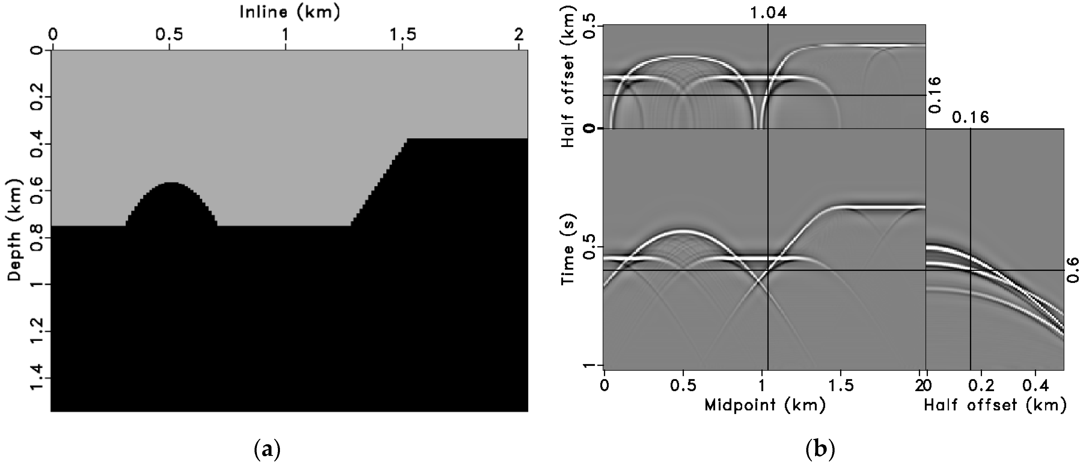
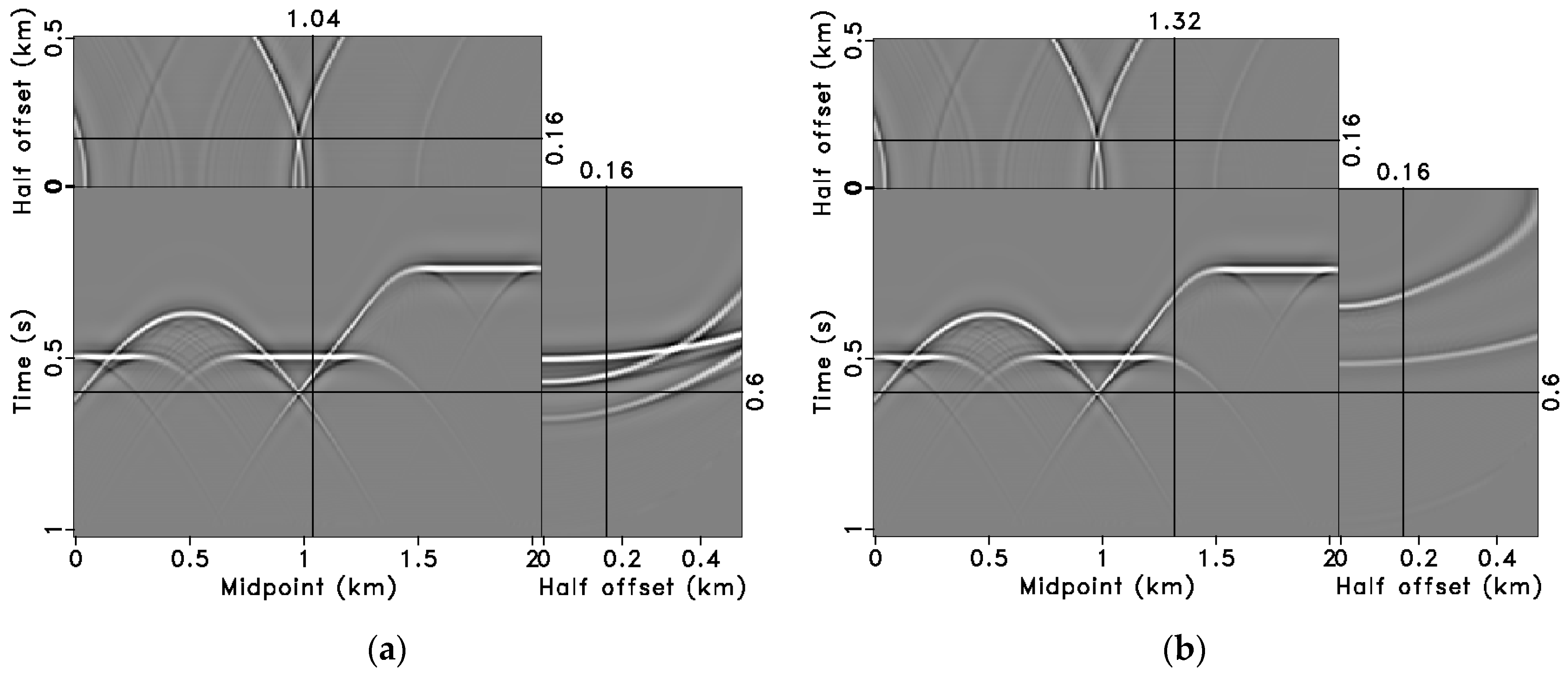
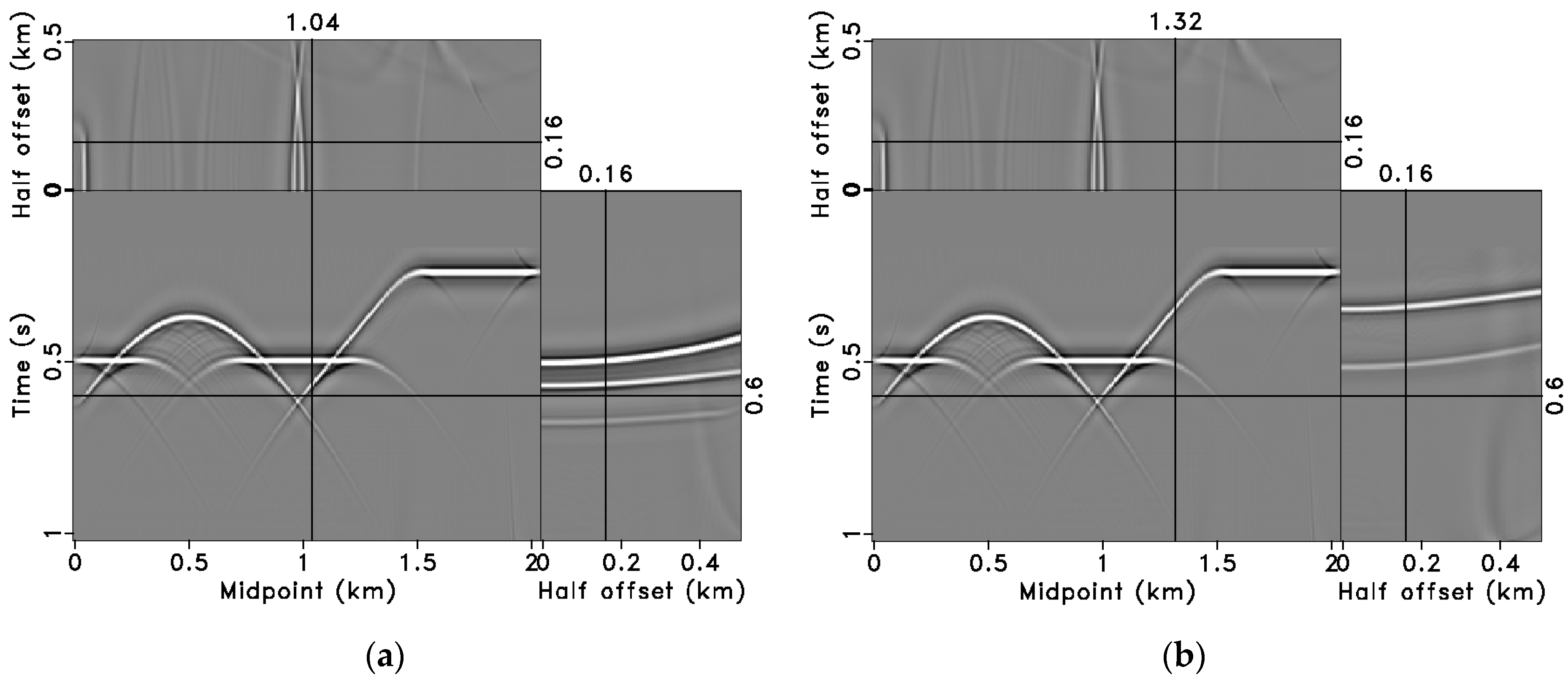
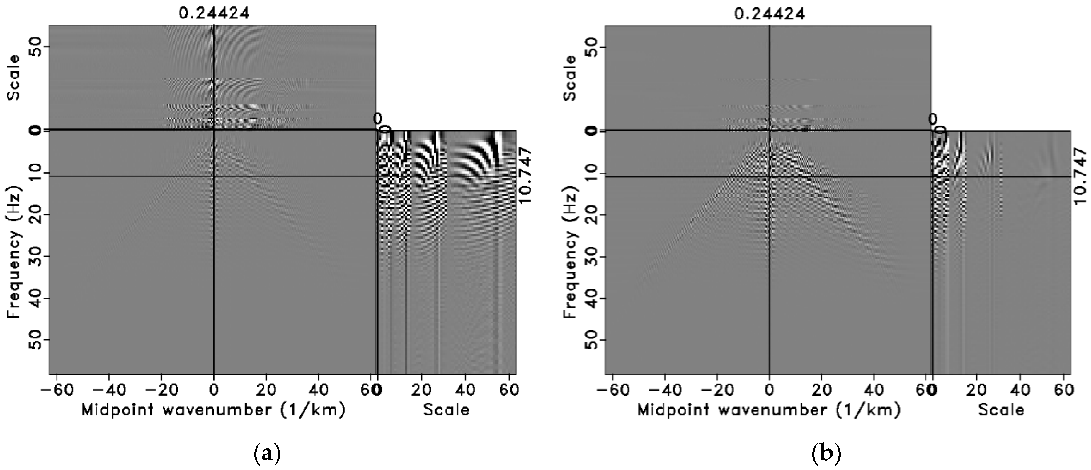
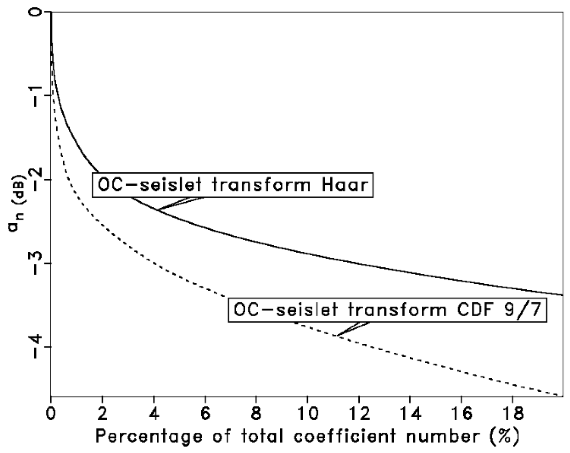
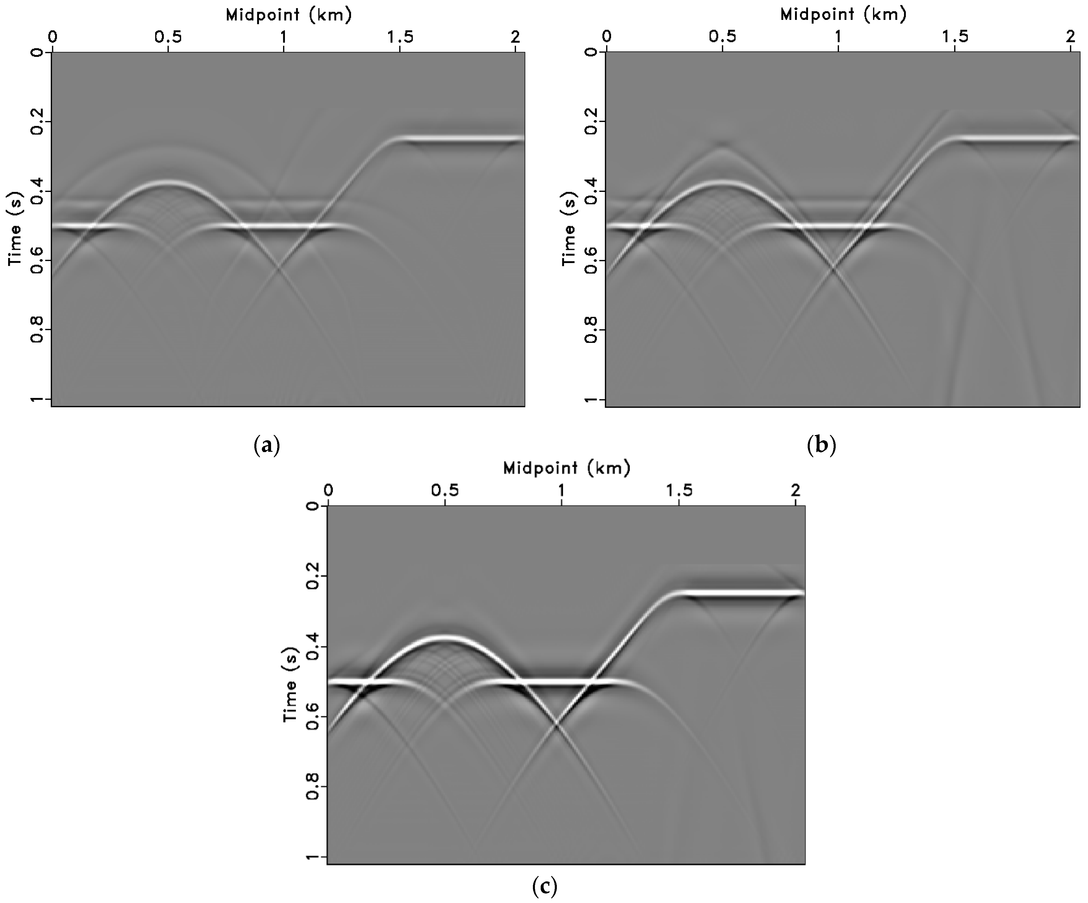
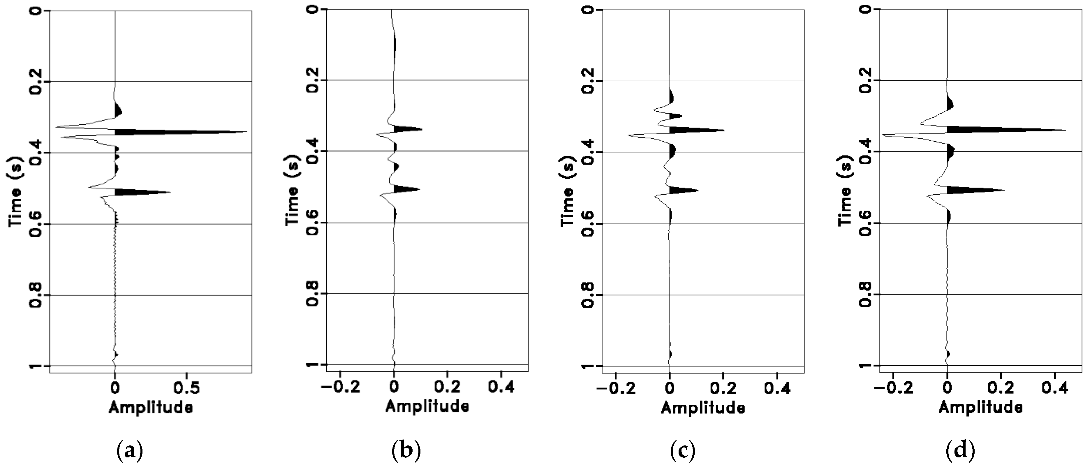
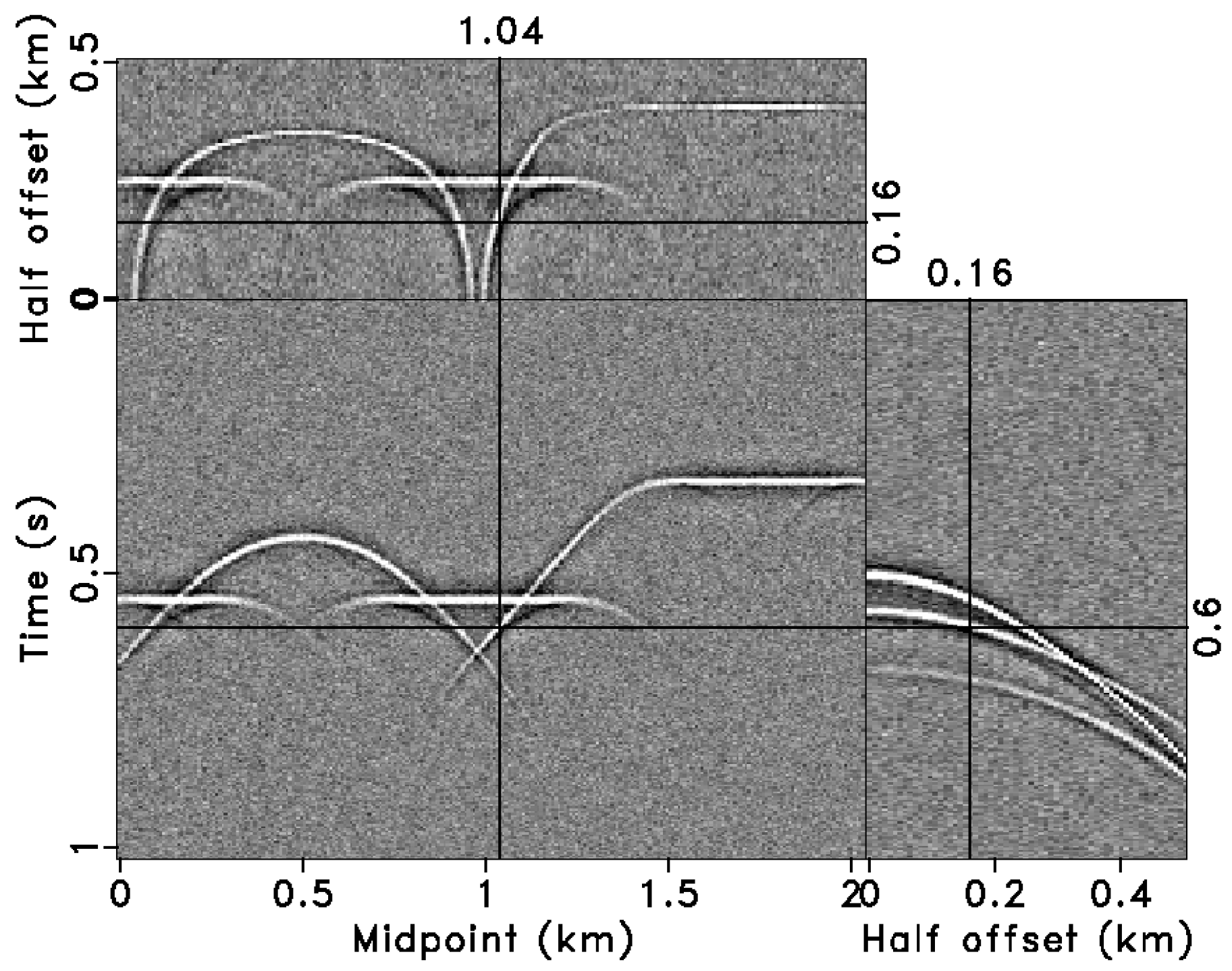
Firstly, the OC-seislet stacking method is tested on the benchmark French model, and Figure 2 illustrates the 2-D slice of the French model (Figure 2a) and the pre-stack CMP gathers (Figure 2b). To evaluate the effectiveness of DMO under inaccurate velocity conditions, NMO is performed using an inaccurate velocity. The NMO results are shown in Figure 3. Figure 3a displays a data slice of the reflection events at the cross point of the CMP gather (CMP location 1.04 km), while Figure 3b presents a data slice of the reflection events with a dipping layer (CMP location 1.32 km). From Figure 3, it is evident that the reflection events have not been properly leveled, indicating that the initial NMO is inaccurate. Additionally, due to the presence of diffraction points in the model, distinct diffraction waves are evident in Figure 3. The results of the time–space domain DMO processing are shown in Figure 4. The DMO for the large offset traces is quite noticeable; the events become more horizontal compared to the NMO results. However, due to inaccuracies in velocity analysis, the events at the large offset position cannot be fully aligned to horizontal, which affects the final stacking accuracy. We use the low-order OC-seislet transform based on Haar wavelets to approximate the coefficient compression of conventional frequency–wavenumber–scale domain DMO stacking; Figure 5 shows a comparison between high-order OC-seislet coefficients and low-order OC-seislet coefficients. The results indicate that the high-order OC-seislet transform provides a higher compression ratio, where the coefficients of the high-order seislet transform are compressed in a small dynamic range along the scale axis. A compressibility comparison is shown in Figure 6, in which we can see that the coefficient magnitude of the high-order OC-seislet transform decreases more rapidly, resulting in less leakage of the frequency energy of the signal information. After the zero scale of the OC-seislet is transformed back to the time–space domain, Figure 7 shows a comparison between NMO stacking (Figure 7a), conventional DMO stacking (Figure 7b), and the high-order OC-seislet stacking (Figure 7c). It can be observed that the proposed method performs better in handling dipping layers and intersecting events, effectively highlighting reflection and diffraction waves while the reducing stacking errors caused by inaccuracies in moveout correction. We further selected four traces at dipping layer positions corresponding to zero-offset sections (Figure 8a) and different stacking sections (Figure 8b–d); the comparison is shown in Figure 8. The first peak amplitude corresponds to the dipping reflection wave, while the second peak represents the diffraction wave at the breakpoint (Figure 8a). Due to the inaccuracy in scanning velocity, the phase of the event cannot be effectively aligned during conventional NMO and DMO stacking, resulting in false events, as shown in Figure 8b,c. In contrast, the high-order OC-seislet stacked trace (Figure 8d) effectively removes the influence of velocity analysis errors, showing a higher similarity to the zero-offset trace (Figure 8a) and ensuring the fidelity of the stacked amplitudes.
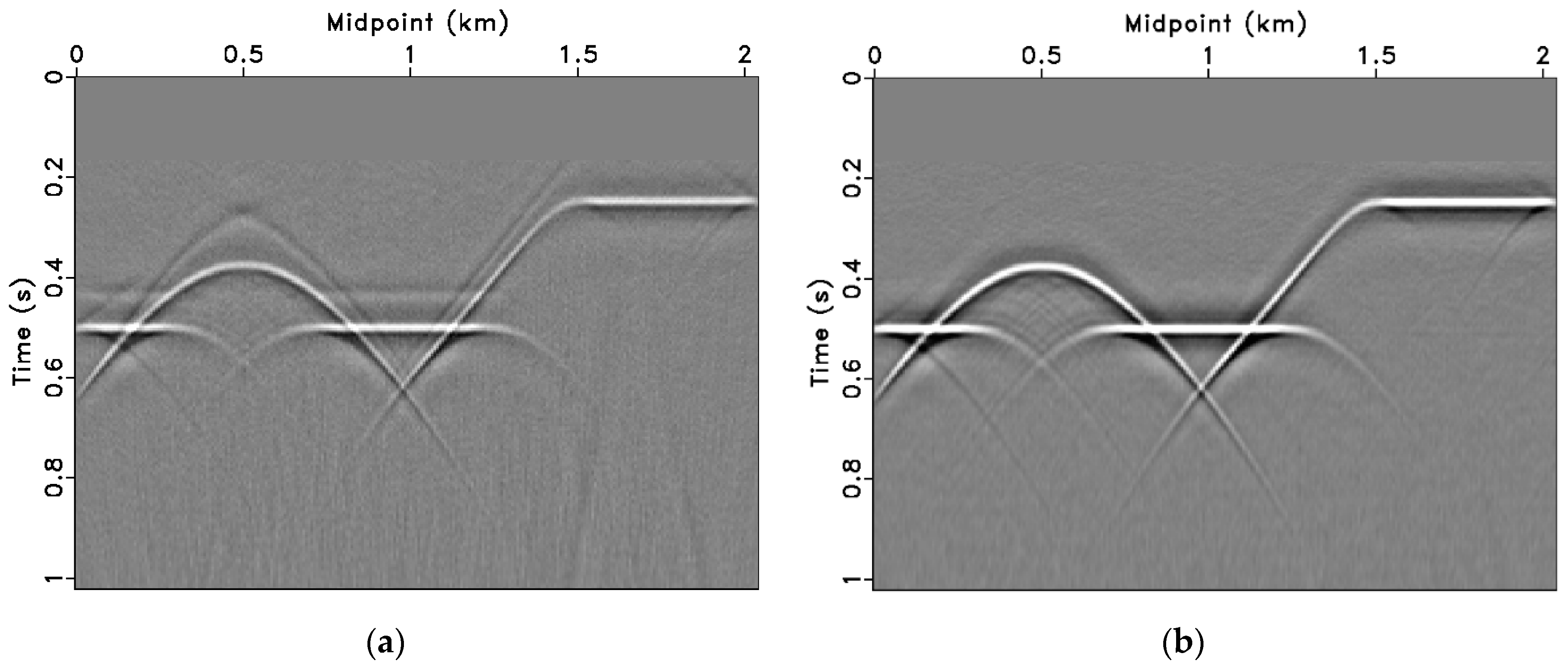
Next, strong random noise is added to the model data, as shown in Figure 9, to test the denoising effectiveness of the OC-seislet stacking. The noise has a significant impact on low-amplitude signals, such as the diffraction waves and reflection waves from dipping layers in this model. To quantitatively analyze the noise suppression performance of different stacking methods, we select the global SNR of the stacked results to evaluate the denoising ability.
S N R = 10 log 10 x 2 2 x - x 2 2
where x represents the noise-free stacked signal, while x - is the noisy stacked signal or the noisy stacked signal after noise suppression. The OC-seislet transform with zero-scale soft-thresholding denoising (a percentile threshold of 70%) is compared with the results of conventional stacking for analysis. The zero-offset trace and traces from different stacking methods at the dipping layer position are shown in Figure 10a–d. Due to the strong denoising ability of the stacking, Figure 10b–d exhibit lower noise amplitudes, with effective wave frequencies and amplitudes being greatly enhanced. Notably, high-order OC-seislet stacking (Figure 10d) reduces the impact of velocity errors, effectively compresses dipping reflection waves and breakpoint diffraction waves, and provides a more accurate amplitude relationship for the wavelets, which results in the better fidelity of the stacking results. A further comparison of the entire stacking sections, shown in Figure 11, demonstrate that high-order OC-seislet stacking significantly improves amplitude fidelity (Figure 11b), with the SNR increasing to 17.17 dB, compared to 9.173 dB for conventional DMO stacking. Additionally, false events caused by inaccurate velocities in moveout correction are visible in the conventional DMO stacking (Figure 11a).

3.2. Field Data Tests

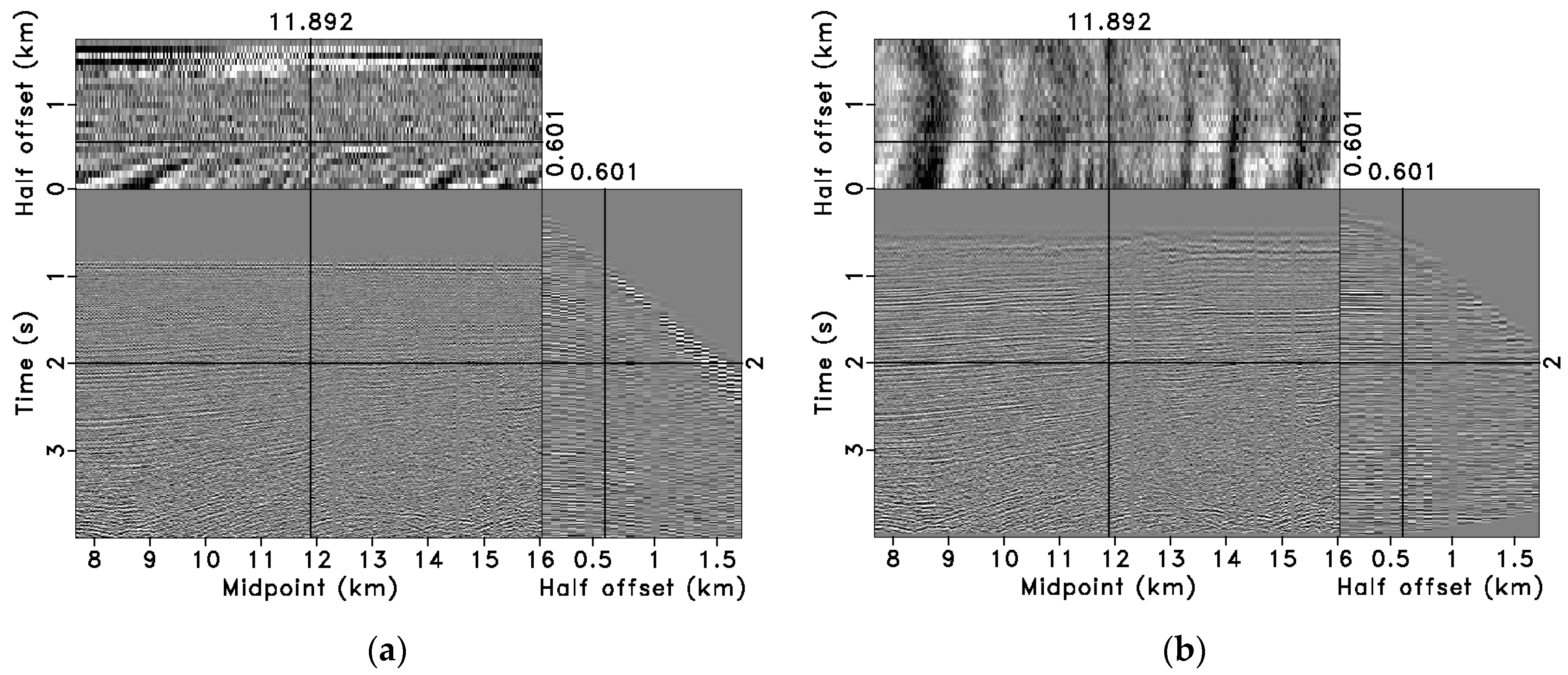
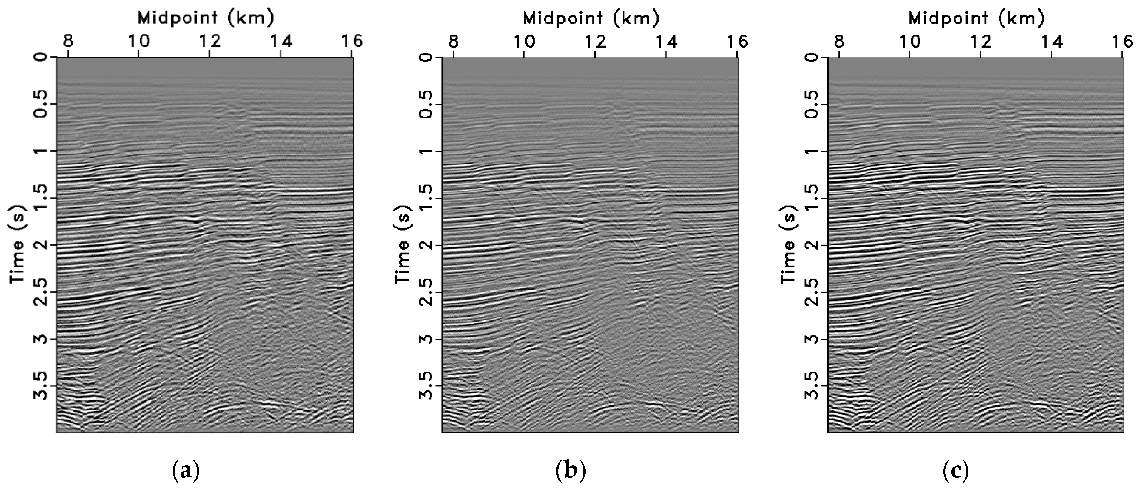
Finally, we use field marine seismic data to validate the effectiveness of the proposed method. This dataset contains abundant fault diffraction waves. Strong noise in the data affects the accuracy of velocity scanning, with the CMP data and NMOed gathers shown in Figure 12a,b. In Figure 12b, we can see that the large offset events after NMO are not horizontal enough; reflection waves and diffraction waves interfere with each other. Traditional NMO stacking suppresses the energy of the diffraction waves (Figure 13a). Although conventional DMO stacking (Figure 13b) retains diffraction information, it suffers from amplitude fidelity issues. Figure 13c shows the proposed high-order OC-seislet stacking results. Compared to conventional DMO stacking, the proposed method effectively stacks both reflection and diffraction waves simultaneously, significantly enhancing the imaging clarity of the diffraction signals at fault positions. It also provides a clearer relationship between deeper scatter waves and reflection waves, offering higher-fidelity stacking results.

4. Conclusions and Discussion

In response to the limitations of traditional DMO stacking in field data processing, this paper proposes a high-order OC-seislet stacking method based on seislet transform theory. This approach effectively reduces the DMO accuracy issues caused by velocity errors in CMP gathers under low-SNR conditions, achieving high-fidelity stacking results and providing an effective partial imaging solution. According to synthetic data stacking results under inaccurate velocity analysis conditions, high-order OC-seislet stacking has improved the SNR 87% compared to traditional equal-weight DMO stacking, with more obvious layering and a more accurate amplitude. The field data with diffraction waves also indicate that this method can efficiently stack reflection waves and weak diffraction waves simultaneously; therefore, the combination of high-order OC-seislet stacking and normalization, as well as thresholding denoising, has potential applications.
Meanwhile, this stacking method also has certain limitations. In Section 2, the stacking theory based on the lifting scheme has the requirement for seismic traces to be 2 n in the seislet stacking. To meet this condition, it is often necessary to expand the original number of seismic traces, which increases the complexity of this method to a certain extent. At the same time, in Section 3.2, the multiple Fourier-transform processing of field data in the frequency–wavenumber domain can result in rounding errors and approximations, requiring the appropriate removal of shallow outliers to count the number of stacking traces. The calculation of the absolute value of the shallow amplitude is not accurate enough. Additionally, the framework of this method also allows for the consideration of other sparse transforms, such as the Radon transform [43], to perform data stacking. This provides new technical ideas for designing stacking methods that balance a high SNR and high fidelity.

Author Contributions

Conceptualization, Y.L. and T.P.; methodology, T.P. and Y.L.; software, Y.L.; validation, Y.L., D.L., P.X. and J.C.; formal analysis, T.P. and Y.L.; investigation, T.P. and Y.L.; resources, Y.L. and D.L.; data curation, T.P. and Y.L.; writing—original draft preparation, T.P.; writing—review and editing, Y.L., T.P. and J.C.; visualization, T.P.; supervision, Y.L.; project administration, Y.L. All authors have read and agreed to the published version of the manuscript.

Funding

This research was partly funded by the National Natural Science Foundation of China, grant number 42474144.

Institutional Review Board Statement

Not applicable.

Informed Consent Statement

Not applicable.

Data Availability Statement

The data presented in this study are openly available in [Model Data] at [http://www.ahay.org/data/french/french.asc], [Field Data] at [http://www.ahay.org/data/midpts/midpts.hh], [Processing Platform: Madagascar based on Ubuntu 22.04] [www.ahay.org]. (accessed on 29 September 2024).

Acknowledgments

T.P. would like to extend his sincere appreciation to the Researchers of the NSGA (Nonstationary Geophysical Signal Analysis) group, Jilin University, China.

Conflicts of Interest

Author Dianmi Liu was employed by the Jilin Oilfield company. The remaining authors declare that the research was conducted in the absence of any commercial or financial relationships that could be construed as potential conflicts of interest.

References

  1. Zhou, Z.; Liu, Y.; Liu, C.; Wang, Q.; Zheng, Z. Attribute of local cosine similarity based on a fast-streaming algorithm. Chin. J. Geophys. 2022, 65, 349–359. (In Chinese) [Google Scholar] [CrossRef]
  2. Mayne, W.H. Common reflection point horizontal data stacking techniques. Geophysics 1962, 27, 927–938. [Google Scholar] [CrossRef]
  3. Hale, D. Dip-moveout by Fourier transform. Geophysics 1984, 49, 741–751. [Google Scholar] [CrossRef]
  4. Judson, D.R.; Schultz, P.S.; Sherwood, J.W.C. Equalizing the stacking velocities of dipping events via Devilish. In Proceedings of the 48th Annual International SEG Meeting, San Francisco, CA, USA, 29 October–2 November 1978. [Google Scholar]
  5. Jamali, E.; Mikada, H.; Asakawa, E. Developing initial model for seismic full waveform inversion using conventional data processing tools. In Proceedings of the 20th International Symposium on Recent Advances in Exploration Geophysics (RAEG 2016), Chiba City, Japan, 24 May 2016; European Association of Geoscientists & Engineers: Chiba City, Japan, 2016; pp. 1–4. [Google Scholar] [CrossRef]
  6. Yilmaz, Ö.; Claerbout, J.F. Prestack partial migration. Geophysics 1980, 45, 1753–1779. [Google Scholar] [CrossRef]
  7. Liner, C.L. General theory and comparative anatomy of dip moveout. Geophysics 1991, 56, 595–607. [Google Scholar] [CrossRef]
  8. Biondi, B.; Fomel, S.; Chemingui, N. Nizar Azimuth moveout for 3-D prestack imaging. Geophysics 1998, 63, 574–588. [Google Scholar] [CrossRef]
  9. Black, J.L.; Schleicher, K.L.; Zhang, L. True-amplitude imaging and dip moveout. Geophysics 1993, 58, 47–66. [Google Scholar] [CrossRef]
  10. Geng, J.; Ma, Z.; Wang, H.; Lei, B. Full wave-equation finite-difference dip moveout. J. Tongji Univ. (Nat. Sci.) 1998, 4, 430–433. [Google Scholar]
  11. Zucca, M.; Crespi, P.; Tropeano, G.; Simoncelli, M. On the influence of shallow underground structures in the evaluation of the seismic signals. Ing. Sismica 2021, 38, 23–35. [Google Scholar]
  12. Bolondi, G.; Loinger, E.; Rocca, F. Offset continuation of seismic sections. Geophys. Prospect. 1982, 30, 813–828. [Google Scholar] [CrossRef]
  13. Bagaini, C.; Spagnolini, U. 2-D continuation operators and their applications. Geophysics 1996, 61, 1846–1858. [Google Scholar] [CrossRef]
  14. Hale, D. A nonaliased integral method for dip moveout. Geophysics 1991, 56, 795–805. [Google Scholar] [CrossRef]
  15. Deregowski, S.; Rocca, F. Geometrical optics and wave theory of constant offset sections in layered media. Geophys. Prospect. 1981, 29, 374–406. [Google Scholar] [CrossRef]
  16. Dix, C.H. Seismic velocities from surface measurements. Geophysics 1955, 20, 68–86. [Google Scholar] [CrossRef]
  17. Geng, J.; Ma, Z. Fast DMO algorithm. Oil Geophys. Prospect. 1994, 29, 462–467. [Google Scholar]
  18. Wang, C. Dip moveout in the Radon domain. Geophysics 1999, 64, 278–288. [Google Scholar] [CrossRef]
  19. Biondi, B.; Ronen, J. Dip moveout in shot profiles. Geophysics 1987, 52, 1473–1482. [Google Scholar] [CrossRef]
  20. Larner, K.L.; Gibson, B.R.; Chambers, R.; Wiggins, R.A. Simultaneous estimation of residual static and crossdip corrections. Geophysics 1979, 44, 1175–1192. [Google Scholar] [CrossRef]
  21. Nedimović, M.R.; West, G.F. Crooked-line 2D seismic reflection imaging in crystalline terrains: Part 1, data processing. Geophysics 2003, 68, 274–285. [Google Scholar] [CrossRef]
  22. Mancuso, C.; Naghizadeh, M. Generalized cross-dip moveout correction of crooked 2D seismic reflection surveys. Geophysics 2021, 86, V285–V298. [Google Scholar] [CrossRef]
  23. Ravve, I.; Koren, Z. Moveout approximation for horizontal transversely isotropic and vertical transversely isotropic layered medium. Part I: 1D ray propagation. Geophys. Prospect. 2010, 58, 577–597. [Google Scholar] [CrossRef]
  24. Koren, Z.; Ravve, I.; Levy, R. Moveout approximation for horizontal transversely isotropic and vertical transversely isotropic layered medium. Part II: Effective model. Geophys. Prospect. 2010, 58, 599–617. [Google Scholar] [CrossRef]
  25. Shragge, J.; Lumley, D. Elliptical dip moveout for 3D seismic imaging in the presence of azimuthal anisotropy. Geophysics 2012, 77, C1–C12. [Google Scholar] [CrossRef]
  26. Notfors, C.; Godfrey, R. Dip moveout in the frequency-wavenumber domain. Geophysics 1987, 52, 1718–1721. [Google Scholar] [CrossRef]
  27. Bale, R.; Jakubowicz, H. Post-Stack Prestack Migration. In SEG Technical Program Expanded Abstracts 1987; Society of Exploration Geophysicists: Houston, TX, USA, 1987; pp. 714–717. [Google Scholar] [CrossRef]
  28. Fomel, S. Theory of differential offset continuation. Geophysics 2003, 68, 718–732. [Google Scholar] [CrossRef]
  29. Fomel, S.; Bleistein, N. Amplitude preservation for offset continuation: Confirmation for Kirchhoff data. J. Seism. Explor. 2001, 10, 121–130. [Google Scholar]
  30. Liu, Y.; Fomel, S. OC-Seislet: Seislet transform construction with differential offset continuation. Geophysics 2010, 75, WB235 –WB245 . [Google Scholar] [CrossRef]
  31. Liu, Y.; Fomel, S.; Liu, C.; Wang, D.; Liu, G.-C.; Feng, X. High-order seislet transform and its application of random noise attenuation. Chin. J. Geophys. 2009, 52, 2142–2151. (In Chinese) [Google Scholar] [CrossRef]
  32. Sweldens, W. Lifting scheme: A new philosophy in biorthogonal wavelet constructions. In Proceedings of the SPIE’s 1995 International Symposium on Optical Science, Engineering, and Instrumentation, 1995, San Diego, CA, USA, 9–14 July 1995; pp. 68–79. [Google Scholar] [CrossRef]
  33. Genovese, F.; Muscolino, G.; Palmeri, A. Effects of stochastic generation on the elastic and inelastic spectra of fully non-stationary accelerograms. Probabilistic Eng. Mechanic. 2023, 71, 103377. [Google Scholar] [CrossRef]
  34. Zhang, S.; Xu, Y. Higher-order correlative stacking for seismic data in the wavelet domain. Chin. J. Geophys. 2006, 49, 554–560. (In Chinese) [Google Scholar]
  35. Fomel, S.; Liu, Y. Seislet transform and seislet frame. Geophysics 2010, 75, V25–V38. [Google Scholar] [CrossRef]
  36. Donoho, D.L. De-noising by soft-thresholding. IEEE Trans. Inf. Theory 1995, 41, 613–627. [Google Scholar] [CrossRef]
  37. Haldorsen, J.B.U.; Farmer, P.A. Resolution and NMO-stretch: Imaging by stacking. Geophys. Prospect. 1989, 37, 479–492. [Google Scholar] [CrossRef]
  38. Fomel, S.; Grechka, V. Nonhyperbolic Reflection Moveout of P-Waves: An Overview and Comparison of Reasons; Technical Report CWP-372; Colorado School of Mines: Golden, CO, USA, 2001. [Google Scholar]
  39. Fomel, S. Applications of plane-wave destruction flters. Geophysics 2002, 67, 1946–1960. [Google Scholar] [CrossRef]
  40. Hu, P.; Li, W.; Yang, P.-C. The application of the method of reconstruction a phase space with higher dimensions to the study of seismic processes and earthquake prediction. Acta Seismol. Sin. 1993, 6, 931–937. [Google Scholar] [CrossRef]
  41. Stanescu, D.; Digulescu, A.; Ioana, C.; Serbanescu, A. A Novel Approach for Characterization of Transient Signals Using the Phase Diagram Features. In Proceedings of the 2021 IEEE International Conference on Microwaves, Antennas, Communications and Electronic Systems (COMCAS), Tel Aviv, Israel, 1–3 November 2021; pp. 299–304. [Google Scholar] [CrossRef]
  42. Daubechies, I.; Sweldens, W. Factoring wavelet transforms into lifting steps. J. Fourier Anal. Appl. 1998, 4, 247–269. [Google Scholar] [CrossRef]
  43. Sun, W.; Li, Z.; Qu, Y. The 3D conical Radon transform for seismic signal processing. Geophysics 2022, 87, 481–504. [Google Scholar] [CrossRef]
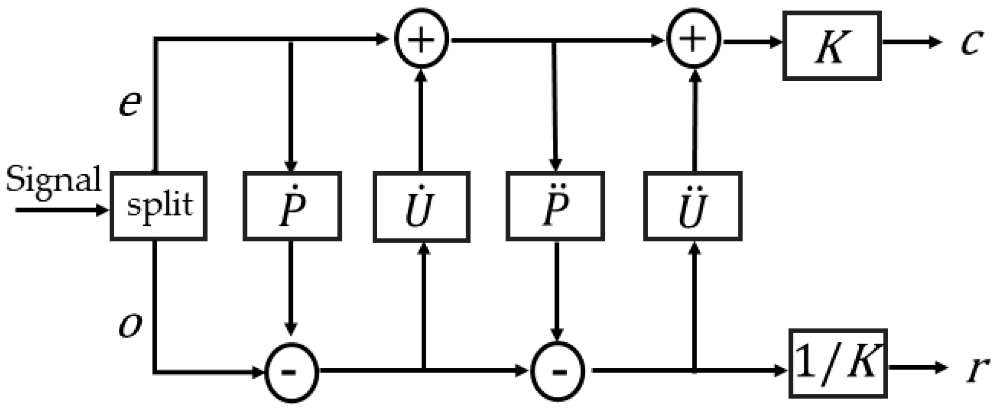
Figure 1. Illustration of high-order OC-seislet transform in one iteration.
Applsci 14 09973 g001
Figure 2. Synthetic French model. (a) 2-D slice out of the benchmark French model; (b) pre-stack CMP data.
Applsci 14 09973 g002
Figure 3. NMO results with inaccurate velocity and excessive moveout of the large offsets, and the events are not horizontal. (a) NMO gathers at the position of the intersected seismic events (CMP location 1.04 km).; (b) NMO gathers at the position of the dipping layer (CMP location 1.32 km).
Applsci 14 09973 g003
Figure 4. DMO results after NMO with inaccurate velocity, the events still not horizontal. (a) Position of the intersected seismic events (CMP location 1.04 km); (b) position of the dipping layer (CMP location 1.32 km).
Applsci 14 09973 g004
Figure 5. OC-seislet coefficients of the input data from Figure 3 along the offset axis using different types of transform basis. (a) Coefficients based on Haar basis, to approximate the coefficient compression of conventional DMO stack; (b) coefficients based on high-order CDF 9/7 basis.
Applsci 14 09973 g005
Figure 6. Transform coefficients sorted from large to small, normalized, and plotted on a decibel scale. Solid line: coefficients based on Haar basis. Dashed line: coefficients based on CDF 9/7 basis.
Applsci 14 09973 g006
Figure 7. Comparison of stacking results using different methods. (a) NMO stacking; (b) conventional DMO stacking; (c) high-order OC-seislet stacking.
Applsci 14 09973 g007
Figure 8. Comparison of zero-offset trace and stacked traces using different methods at dipping layer position (CMP location 1.32 km). (a) Zero-offset trace; (b) NMO stacked trace; (c) conventional DMO stacked trace; (d) high-order OC-seislet stacked trace.
Applsci 14 09973 g008
Figure 9. Synthesized French model data with strong random noise added.
Applsci 14 09973 g009
Figure 10. Comparison of zero-offset trace with noise and stacking results using different methods at dipping layer position (CMP location 1.32 km). (a) Zero-offset trace; (b) NMO stacked trace; (c) conventional DMO stacked trace; (d) stacked trace using high-order OC-seislet with thresholding.
Applsci 14 09973 g010
Figure 11. Comparison of different stacking methods. (a) Conventional DMO stacking section (SNR = 9.173 dB); (b) stacking section using high-order OC-seislet with thresholding (SNR = 17.17 dB).
Applsci 14 09973 g011
Figure 12. Field seismic data. (a) CMP gathers with random noise; (b) conventional NMO results using scanning velocity.
Applsci 14 09973 g012
Figure 13. Comparison of stacking results using different methods. (a) NMO stacking with stronger reflected waves and very weak diffracted waves; (b) conventional DMO stacking with diffraction waves enhanced but reflected waves decreased; (c) high-order OC-seislet stacking with thresholding can simultaneously efficiently stack reflected and diffracted waves.
Applsci 14 09973 g013
Disclaimer/Publisher’s Note: The statements, opinions and data contained in all publications are solely those of the individual author(s) and contributor(s) and not of MDPI and/or the editor(s). MDPI and/or the editor(s) disclaim responsibility for any injury to people or property resulting from any ideas, methods, instructions or products referred to in the content.