Abstract
The energy efficiency in metal cutting is, sometimes, very low. Recent studies show that the energy consumed for detaching chips represents only about 15% of the total energy involved in material machining. The available solutions for energy optimization in cutting processes mentioned are the improvement of manufacturing equipment, the optimization of processes, and appropriate production scheduling. Already-performed research shows that to increase energy efficiency, the cutting force must be reduced, for example, by reducing the depth of the cut and by increasing the feed rate. However, this is applicable when the cutting force is quasi-constant during the process, which is not the case for gear teeth cutting when the cutting force significantly varies. The present paper proposes a new solution for energy efficiency increase in gear teeth cutting, namely, the smoothing of the cutting force variation during the machining process, by keeping the area of the detached chip section quasi-constant during the cutting process. This can be reached by replacing the constant rolling feed, currently used in gear teeth cutting, with a rolling feed that varies after an appropriate law. An algorithm dedicated to implementing this solution has been developed. It uses graphical modeling in CATIA to find the variation in the detached chip area. Original MatLab R2018a applications were developed (i) to identify the analytical form of the law that approximates this variation and (ii) to find the variation law of the feed during the rolling motion, if imposing a constant area of the detached chip. The algorithm was successfully applied in the cases of toothing with a rack tool (by slotting) and with a pinion cutter (by slotting and turning). A technical solution for method implementation in practice is also presented.
1. Introduction
Manufacturing processes are an important component of industrial activity and occupy an essential position in the global economy. Manufacturing equipment supports raw materials’ metamorphosis into products through such processes by consuming, almost every time, electric energy. As manufacturing occurs, unwanted waste and emissions are generated at the same time with the added value. Lowering the consumption of all kinds of resources involved in manufacturing—electric energy the first of them—without affecting the process performance, became a sine qua non condition to be met for reaching sustainable manufacturing. In general, this can be achieved by increasing its efficiency.
The energy efficiency in metal cutting is, sometimes, very low. For sampling, recent studies [1,2] show that the energy consumed through chip detaching represents only about 15% of the total energy involved in hard and fragile materials machining. Despite this, until a few years ago, the optimization of machining operations from an energy efficiency point of view was not convincingly approached, with productivity and costs being the main targets. Due to the well-known problems generated by human activities that impact the environment, with negative and unpredictable consequences, the situation has dramatically changed. Producing electricity sustainably and energy efficiency have become top priorities on a worldwide scale, and the manufacturing domain is no exception.
This study [3] has established a framework for energy performance improvement in manufacturing and subdivides the methods to be used for this purpose into four aspects: energy monitoring, evaluation, optimization, and benchmarking. Moreover, the available solutions for energy optimization are the improvement of manufacturing equipment, the optimization of processes and parameters, appropriate production scheduling, and a management system.
In the part machining process, cutting parameters have a huge impact on energy and material consumption, cutting the time and economy of the manufacturing system. Many researchers have been engaged in energy-efficient cutting parameter optimization, and a significant amount of the dedicated literature has been published in recent years. For sampling, paper [4] presents a method for such optimization, aiming to balance cutting indexes, i.e., carbon emissions, cutting time and cutting cost, in the part machining process, by using non-cooperative game theory integrated NSGA-II. The article [5] shows an integrated model for machining energy consumption, designed to enable the use of the Simulated Annealing technique to find the optimal spindle rotation speed and feed rate that result in the minimum machining energy consumption by also considering the non-cutting energy consumption. Other research [6,7,8] approaches the same type of problem based on different energy models and optimization techniques. Paper [9] analyzes energy-efficient cutting parameter optimization using the experimental design method.
Gears are the most common solution to transmitting rotation motion with power between mW and hundreds of kW in devices from the medical domain to heavy, energy-producing, or aircraft industries [10]. Naturally, there is a significant number of gears in worldwide machinery, among which one can find many types of gears and a certain number of shapes for tooth profiles, as well. The most used types of gears are cylindrical gears, bevel gears, and worm gears [11], while the most popular tooth profile is the involute, due to its unbeatable advantages regarding contact between conjugated teeth profiles [10,11].
In gear manufacturing, the most particular issue of concern is teeth machining. Here, the generating of involute teeth profiles can be performed by copying the tool axial profile or by applying the so-called “rolling method”, which is the currently applied solution [12]. The teeth flanks generated by rolling involve, besides common cutting motions (specific to turning/milling/grinding/slotting, depending on the applied process), a feed motion precisely reproducing the relative motion between the centrodes associated with the cutting tool and the machined part—the rolling motion [12]. In all cases, the speed of this motion is set at the beginning of teeth cutting and is kept unchanged throughout the process [13].
Despite the inexistence of a precise formula for calculating the cutting force in a given cutting process, all the existing formulas, proposed by different researchers, accept the direct connection between the cutting force magnitude and the area of the detached chip section [14,15,16,17,18]. The modeling of the gear teeth-cutting processes [19,20] shows a significant variation in this area during teeth machining, which further leads to a high time variation in the cutting force. In other words, the teeth machining process is characterized by important non-uniformity from an energetic point of view. This indicates the variation in the electric power absorbed by the driving system of the used machine tool and determines, obviously, the diminishment of energy efficiency.
The authors of [21] analyzed the influence of the cutting force on machining process efficiency and found that to increase energy efficiency, the cutting force must be reduced, for example, by reducing the depth of the cut and by increasing the feed rate. However, they have addressed the case when the given machining operation is performed by using an unchanged regime, during which the cutting force is considered quasi-constant. When the cutting force significantly varies, the above-presented situation specific to gear teeth cutting makes the cutting parameter optimization aiming for energy efficiency less applicable according to the current general approach.
The present paper proposes an innovative approach leading to an energy efficiency increase in gear teeth cutting characterized by a new strategy: the smoothing of the cutting force variation during the machining process. A dedicated method, which enables the implementation of this strategy, based on playing the rolling motion with a variable and convenient speed was developed accordingly.
The present paper is structured as follows: Section 2 deals with describing this method, Section 3 presents method application in the cases of some typical methods for gear teeth cutting, Section 4 describes a technical solution proposed for method implementation, and Section 5 presents the conclusions.
2. Method Description
2.1. Principle of the Method
Smoothing of cutting force variation requires that the area of the detached chip section remains quasi-constant during the cutting process (see the previous section). In gear teeth machining, there are two potential solutions to achieve this result:
- -
- The constructive modification of the cutting tool;
- -
- The appropriate variation in the cutting tool feed relative to the worked piece.
Both solutions start from finding the variation law for the area of the detached chip section, which can be found by modeling the toothing process. Such modeling was realized by analytical and specific numerical methods [19] in the cases of gear teeth machining by slotting (with a rack tool or with a pinion cutter) and by hobbing.
For sampling the tool constructive modification, in the case of the rack tool, it may consist of giving different angles of inclination to the successive teeth flanks or adopting different heights or different thicknesses for the successive teeth [19,20]. However, this solution is difficult to apply due to the complex geometry of the tool, which becomes expensive, while the induced results have shown only a partial smoothing of the chips section area, hence a partial smoothing of the cutting force.
Concerning cutting force smoothing by appropriate variation in the cutting tool feed rate, there are few mentioned results. When toothing by employing the rolling method on conventional equipment, the tool feed motion is mechanically controlled through elements of the rolling kinematical chain in a discrete manner. The pre-established increment of motion is impossible to modify throughout the process.
The principle of the proposed method is to perform the teeth-cutting process by rolling with variable increments, according to an appropriate, previously established law. This can be reached by modifying the rolling kinematical chain, such as the tool feed motion, which is independently driven by a numerically controlled stepper motor.
The implementation of the proposed method requires the steps presented below.
2.2. Graphical Modeling of the Gear Cutting Process
Unlike the already existing solutions for analytical modeling of the toothing process, here, we propose the application of graphical modeling in specialized software, namely CATIA. Thus, one can take full advantage of the available facilities and the accuracy of the results.
Graphical modeling starts with the creation, in separate files, of the models for both the worked piece and the cutting tool. The models are obtained by extruding with a Pad tool [22] at convenient dimensions. Drawings are executed in the Sketch module of CATIA, in which the dimensions correspond to the active tool part and the gear exterior diameter.
Certain geometrical and dimensional restrictions are imposed on these models, such as the correct relative positioning between the tool and the worked piece, meaning that the tangency between their associated centrodes is reached [23].
Subsequently, the type of motion (rotation and/or translation) and the motion increments to be applied to the models are established so that the kinematics of the addressed cutting process are correctly reproduced and obey the specific rolling condition [11].
When addressing the most usual case of machining the teeth of a cylindrical gear, the workpiece model is very simple, i.e., a disc having the radius and the thickness equal to the ones of the blank considered for starting the process. Concerning the cutting tool model, this depends on the considered toothing solution, which may use a rack tool, a pinion cutter, a rotating cutter, etc.
2.3. Finding the Variation Law for Detached Chip Area
As already mentioned in the previous section, there is a close link between the cutting force magnitude and the detached chip area. For simplicity, without any direct impact on the proposed method’s effectiveness, we will further accept a proportional relation between them. Hereby, the shape of the cutting force variation law is similar to the shape of variation for the detached chip area.
Given the periodicity of the process (except for tool engagement and disengagement phases) and due to the successive machining of consecutive teeth, it is sufficient to look for the variation law during (i) the tool engagement phase, (ii) the complete machining of a tooth, and (iii) the tool disengagement phase.
Finding the variation law for detached chip area starts by determining the detached chip area for each increment of the toothing process, which corresponds to an increment of the rolling motion, respectively, to one kinematical cycle of the cutting motion. In order to do so, the next four-step algorithm must be followed:
- (a)
- Firstly, the tool model is imported into the file which contains the workpiece model.
- (b)
- The toothing process is then simulated by giving each of the two items (the cutting tool and the workpiece) the motion corresponding to the one increment of the rolling motion, after which the two items are overlapped.
- (c)
- The option Remove of Operation modeling tool [22] is subsequently applied; thus, one item is subtracted from the other, the result being a new item, which is the workpiece from which the common region (corresponding to the detached chip) was eliminated.
- (d)
- The detached chip area is, finally, calculated as the difference between the workpiece area that was measured before and after the intersection, by using the Measure Item tool from the Measure toolbar [22].
Here, we must mention that the accuracy of the area measurement we thus achieved, if performed as suggested above, is 10−3 mm2.
Since the next step requires an analytical expression of the variation law for the detached chip area A, a function f approximating the series of areas calculated from the first up to the last contact point between the cutting tool and the worked piece has to be found. The Curve Fitting toolbox of MatLab may be used, for example, for this purpose [24].
As in all the gearing processes addressed here, the worked piece has rotational motion, and the position of the coupled cutting tool and worked piece will be defined by the angle φ made by the worked piece with a reference start position, corresponding to the first contact between the two elements (when φ = φmin). Obviously, the maximum value φmax, corresponding to the last contact, depends on the actual conditions of a given process. Thus, it can be written as
2.4. Finding the Feed Motion Variation Law
Let us suppose that the feed increment of the rolling motion corresponds to the workpiece rotation of ∆φ0 angle. If we intend to smooth the detached chip area to Ac value for any φ ∈ [φmin … φmax], then the following relations are obtained:
In Equation (2), ∆φ means the rolling motion increment (instead of ∆φ0) required to obtain the Ac value for the detached chip area (instead of A(φ)). Obviously, as f varies with φ, ∆φ also varies, so one can notice that smoothing the detached chip area means working with variable federate after an appropriate variation law. We have developed an original MatLab application to find this law in discrete form, the input data being:
- -
- The limits of the variation domain for the workpiece position angle φ, φmin and φmax, corresponding to the machining of a gear tooth interval.
- -
- The analytical expression of the f function, meaning the variation law for the detached chip area and the rolling motion increment ∆φ0, based on which this law was determined.
- -
- The imposed value for the detached chip area, after variation smoothening, Ac.
- -
- Some auxiliary variables, namely the incremental parameter dφ (∆φ following to be determined as ∆φ = i ∙ dφ, i = 1, 2, …), and the maximum admissible deviation from Ac for the value actually obtained of detached chip area Aca during the smoothened process, ε.
The application result consists of a series of (variable) values for the federate of the rolling motion, ∆φ1, ∆φ2, …, ∆φns, such as
In Equation (3), ns means the number of kinematical steps needed for the complete machining of a gear tooth interval, which is obviously different from n number of steps completed when machining the same gear tooth interval with constant increments of the rolling motion, and ε means a quantitative parameter defining the width of the interval within which the detached chip area may vary. These parameters are not specifically related to any toothing method. The parameter ns is related to process productivity, while ε mainly impacts the computing speed of the software used in the method application. The parameters ns and ε should be set according to the manufacturer option.
3. Method Application
To exemplify the application of the method, three case studies are presented in the following section: the case of processing involute teeth with a multi-tooth rack tool, the case of processing the same type of teeth with a pinion cutter and the case of processing involute worms by turning with a pinion cutter. All three case studies are presented below with specific data.
3.1. The Rack Tool Case
The problem of generation with the multi-tooth rack tool, which is the most used practical case when generating teeth on MAAG machines, proves to be very different from the case of the single-tooth rack since a number of successive teeth of the tool are simultaneously in contact with the workpiece. This leads to an important change in the law of the cumulative area of the chips formed by the tool edges [25].
The case of generating the straight teeth of a gear which has 30 teeth and the module of 10 mm was simulated, in the CATIA environment, according to the methodology presented in Section 2 of the present paper. A disc workpiece with a diameter of 320 mm was used. The disc thickness is irrelevant. The rack tool was supposed to have 4 teeth.
3.1.1. Analytical Modeling
Figure 1 shows the couple of running centrodes formed by C1—the workpiece centrode (circle of radius Rr) —and C2—the centrode of the generating rack (straight line tangent to the circle of radius Rr).
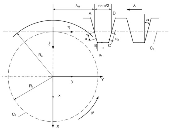
Figure 1.
Kinematics of teeth generation with a rack tool [26].
At the same time, the reference systems associated with the centrodes are defined, respectively:
- -
- xyz is the fixed system, with the z-axis as the axis of workpiece rotation;
- -
- XYZ—mobile system, attached to C1 centrode;
- -
- ξηζ—mobile system, attached to C2 centrode.
The variable parameters associated with the workpiece and rack tool motions are as follows:
- -
- φ, meaning the rotation angle around the z-axis;
- -
- λ—translation parameter, along the η-axis.
By using these parameters, the running condition of the two centrodes is defined as:
Within the space ξηζ associated with the rack tool, the shapes of the tool flanks are defined as follows (see Figure 1):
The parameters u, u1, and u2 give the position of the current point on tooth sides, the parameter λ0 represents the initial value of translation parameter λ, and the parameter α is the inclination angle of the rack tool flank (see also Figure 1).
The expression of the relative motion between the mobile systems ξηζ and XYZ is as follows:
where ω3 means the matrix of coordinates transformation corresponding to rotation around the z-axis and a—the matrix of coordinates transformation corresponding to translation along the η-axis.
3.1.2. Graphical Modeling
The tool and part models were generated in CATIA by successively following the stages presented in Section 2 in the toothing process with the rack tool (see Figure 2 and Figure 3).
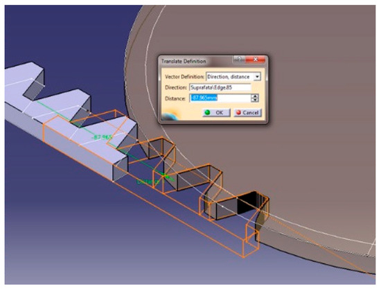
Figure 2.
Simulation of toothing with the rack tool [25].
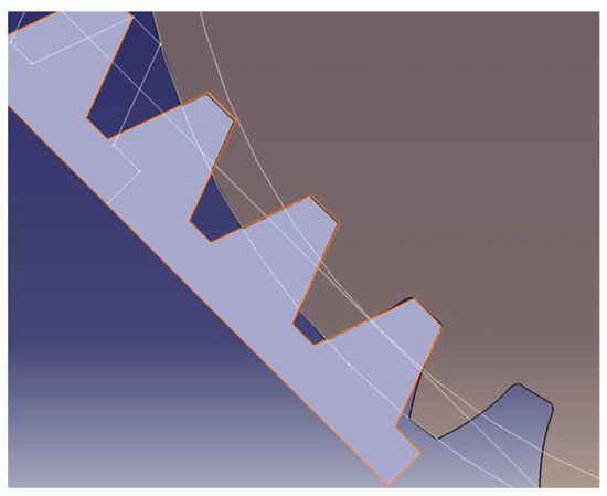
Figure 3.
Four-tooth rack—step 1, after indexing [26].
The motion increments Δλ and Δφ for the two moving centrodes are as follows:
The detached chip area variation, which resulted in the addressed case of simulating the toothing process, is presented in Figure 4 [25].
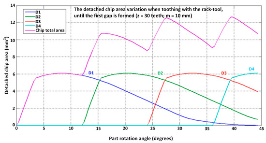
Figure 4.
The detached chip area variation when toothing with the rack tool [25].
Both the variation in the detached chip cumulative area in the toothing process and the variation in the area of the chip detached by each tooth of the tool can be observed.
After each repositioning of the rack tool, there will be the same variation law for the chip cumulative area, which has a periodicity of 360°/z = 12°, in the presented case.
Using the data regarding the evolution of the total section of the chips, it is possible to identify a function that best approximates the function shape. Thus, the most suitable of the approximation variants, which are available in Matlab, was as follows:
where the values of the coefficients a1, a2, …, a8, b1, b2, …, b8 and c1, c2, …, c8 are calculated by the program for approximating the graph of the given function. The values determined by knowing the form of the function f and the coefficients are presented in Figure 5, as detailed in previous work [25].
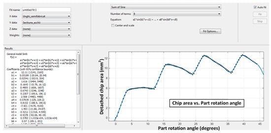
Figure 5.
Approximation function of the chip section variation [25,26].
Using a dedicated application in Matlab [24,25], the feed value Δφi was determined to obtain a quasi-constant area of the chip section.
By running the application for f function smoothing, the values of the angular step of the workpiece rotation were obtained, for which, in compliance with the condition of rolling without slipping, the values of the chip section area are close to the ones imposed by the operator.
The value of the total chip section area detached at a double stroke of the generating tool was limited to 6 mm2, the machine stress being at the level of teething with a single-tooth rack tool that has a fixed angular pitch of 0.4°/double stroke, as shown in Figure 6. By double stroke, here, we mean the back-and-forth displacement of the tool between two given points.
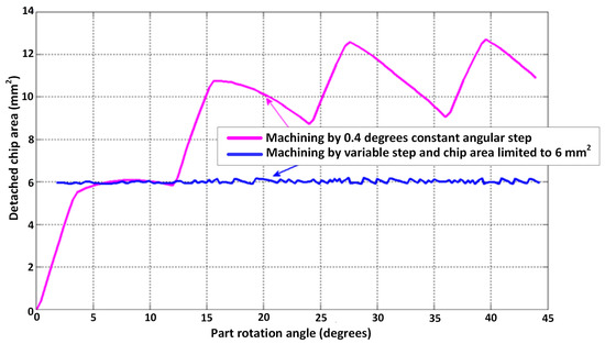
Figure 6.
The variation in the chip section area when toothing with the rack tool: constant step vs. variable step cases [25].
The number of double strokes the machine must complete to reach this result increases from 110 to 165, without being relevant, because by setting a higher value for Ac, the required number of double strokes will diminish.
The variation in the angular step in the range 0 … 44° is shown in Figure 7. The value of 44° means a rotation corresponding to a complete passage of the rack tool.
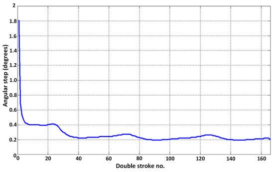
Figure 7.
The variation in the angular pitch of the workpiece to obtain a constant cumulative chip area of 6 mm2 [25].
Finally, it can be concluded that the results presented above support the viability of the imagined solution, which, implemented on a specialized numerical control machine that works with a circular feed of the variable workpiece, can lead to the uniformity of the size of the detached chip section area at a double stroke of the tool and, therefore, of the main cutting force magnitude.
3.2. Pinion Cutter—Slotting Case
Another example of a process, that is frequently used for machining internal and external involutes teeth, is slotting by using the pinion cutter. In the following section, the application of the smoothing method of the area of the detached chip section is also exemplified. The application steps are the same as in the previous case; however, the main dissimilarity is that the centrode attached to the tool is a circle.
The solution to modify the teeth generation process by varying the rolling feed was also considered without distorting the specific mechanism of rolling between the centrodes associated with the tool and the generated workpiece. A relatively uniform size of the detached chip area can thus be ensured, with effects on the size of the main cutting force, the size of the asperities of the generated surfaces and the reduction in wear on the teeth of the cutting tools.
The application of the method in the case of pinion cutter processing can be carried out in both situations of toothing a gear or a gear rim. In the following, the application of the method is presented in the case of machining a straight teeth gear.
3.2.1. Analytical Modeling
The reference systems are defined, in correlation with Figure 8, as follows:
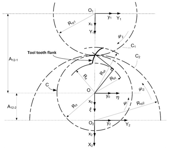
Figure 8.
Running centrodes and reference systems [27].
- -
- x0y0z0 is a fixed system solidary with the z0-axis of the pinion cutter model;
- -
- x1y1z1 is a fixed system attached to the z1-axis of the generated gear;
- -
- x2y2z2 is a fixed system attached to the z2-axis of the generated gear rim.
The fixed systems have parallel axes that are oriented in the same direction. The distances between the z0, z1, and z2 axes are defined by the A12-1 and A12-2 quantities, respectively. At the same time, mobile reference systems are also defined:
- -
- ξηζ, originally overlapped with x0y0z0, with the center in O1, in solidarity with the centrode of the pinion cutter—C.
- -
- X1Y1Z1, originally overlapped with the x1y1z1 system, where Z1 is the gear axis.
- -
- X2Y2Z2, originally overlapped with the x2y2z2 system, where Z2 is the gear rim axis.
Thus, the running condition is as follows:
The matrix equation of the relative motion of the pinion cutter, solidary with the system ξηζ, with respect to X1Y1Z1, is as follows:
In Equations (9) and (10), φ and φ1 are angular parameters in the rotational motion of the pinion cutter and the generated workpiece.
Transforming and replacing and, at the same time, considering that the relationship between the angular parameters φ and φ1 is given by the rolling condition of the pinion cutter and workpiece centrodes, the increment Δφ1 was determined as the size of the workpiece rotation angle corresponding to a double stroke of the tool:
where sc is the circular feed, ncd is the number of double strokes of the pinion cutter and Rrp1 is the rolling radius of the workpiece centrode.
3.2.2. Graphical Modeling
The modeling was carried out in a CATIA graphical design environment due to the development of a numerical application, which was designed to assess both the shape and area of the chip detached from the teeth of the pinion cutter in the chipping process, which is particularly complex and laborious at the same time.
The case of toothing a pinion with zp = 30 teeth or m = 10 mm with a pinion cutter having zs = 20 teeth was addressed for sampling the method application.
The rotational increment of the workpiece was considered Δφ = 1° and, therefore, the rotational increment of the tool was Δφ = 1.5°.
Using CATIA facilities, the variation in the size of the detached chip was determined, depending on the relative position of the tool to the workpiece (Figure 9). Figure 10 shows the modeling of the toothing process with the pinion cutter, the variant with constant circular feed and the toothing stage when the pinion cutter works with both radial and circular feeds.
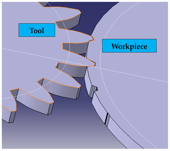
Figure 9.
The relative position of the tool and workpiece models in the toothing process [27].
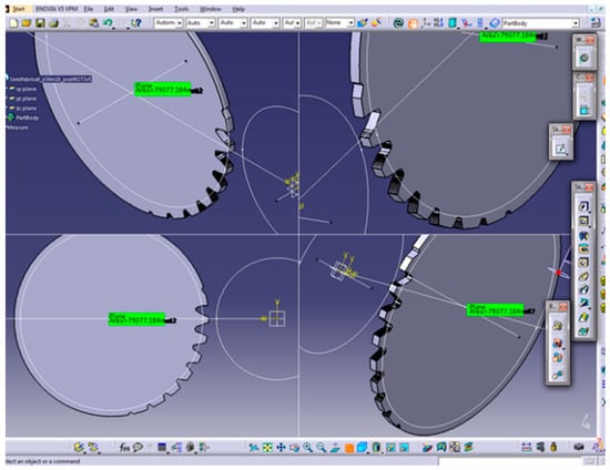
Figure 10.
Toothing with a pinion cutter (step 92—toothing with constant circular feed) [25].
According to the specifics of the toothing by pinion cutting method, two phases of the process are distinguished, namely, toothing with radial feed motion (penetration) and toothing without radial feed motion. The evolution of the chip size, depending on the relative position of the tool and workpiece, can be seen in Figure 11.
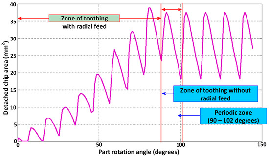
Figure 11.
Variation in detached chip area when toothing with the pinion cutter [25].
When analyzing Figure 11, two regions can be distinguished. The first region shows a variation in the size of the detached chip due to the interaction of the tool with the workpiece, the tool having both a circular feed, to achieve the rolling motion, and a radial penetration motion (up to the tangency of the rolling circles, which happened in the example given previously, at the 90th double stroke).
The second region starts after the 90th double stroke and shows an oscillatory variation in the chip size from a median size until the end of the entire tooth generation.
For the first region, Function (12) was identified in the Matlab environment, as shown in Figure 12, to approximate the graphic distribution of the determined values of the detached chip area:
where a1, b1, c1, a2, b2, c2, … a7, b7, c7 are the calculated coefficients.
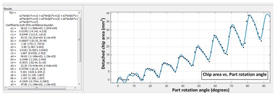
Figure 12.
Approximation function of the detached chips section in the machining of a toothed wheel with the pinion cutter tool (radial feed zone) [25].
The oscillation of the cumulative area of the chip size, corresponding to the second area of the graph, from the angular interval 90° … 102°, is, for the given example, between 18 and 37.5 mm2, the variation being from single to more than double.
By processing the data regarding the variation in the chip area measured in the range of 90 … 102°, a polynomial approximation function is obtained (see Figure 13), which will be used to calculate the feed required to be applied to the tool, to obtain chips cumulative area of about 10 mm2.
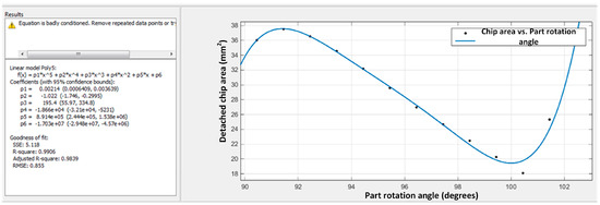
Figure 13.
Approximation function of the area of the detached chip when toothing the gear with a pinion cutter (repetitive zone) [25].
The comparison between the size of the chips obtained in the two alternatives, with constant feed and with variable feed, is presented in Figure 14.
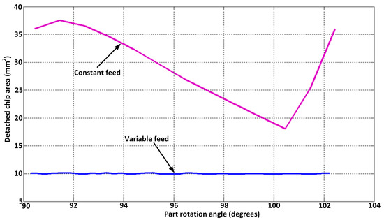
Figure 14.
Comparison between the detached chip area constant vs. variable circular feed (toothing without radial feed motion) [25].
Then, the application was used to determine the values of the feed per double stroke in order to obtain a uniformity of the detached chip area.
The results obtained for the variation in the detached chip area during toothing with the pinion cutter in both cases, respectively, with variable rolling feed and with constant rolling feed, are compared in Figure 15.
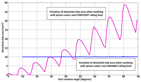
Figure 15.
Variation in the chip section when machining a toothed wheel with the pinion cutter tool (radial feed area); constant feed vs. variable feed (toothing with radial feed motion) [25].
To perform cutting with a constant section area of this value (10 mm2), 130 double strokes are required, compared to 90 double strokes in the case of cutting with constant feed.
In conclusion, for this case, it can be stated that changing the circular feed when toothing cylindrical gears with an involute profile by using pinion cutters results in chips with a relatively constant area throughout the processing. The chip area can be set to values that allow the optimization of the energy load of the toothing machines. It should be noticed that the number of double strokes necessary to realize the toothing increases with section reduction.
To establish the approximation functions of the chip size distribution during the full toothing of the gear, the two parts of the graph must be analyzed separately: the starting zone, where, in addition to the circular rolling feed, there is also a radial feed, and the subsequent zone, where the rolling centrodes of the tool and workpiece become tangent.
3.3. The Pinion Cutter—Turning Case
The development of graphical programming environments has allowed the rigorous representation of the shape of tools that are generated by wrapping the teeth or helical surfaces. The generation processes can also be analyzed in terms of determining the shape of the chips and their area to even out the energy load of the tool edges.
In what follows, the paper presents the results of the application of the algorithm for determining the areas of chips detached by turning with the rotary cutter when generating cylindrical involute worms. The pinion cutter profile was assumed to be involute.
3.3.1. Analytical Modeling
For example, it was considered that the tooth of the pinion cutter (the generating tool) belongs to an ordered vortex of involute profiles—with straight teeth and without correction, respectively.
Then, the involute model was represented (Figure 16), and the cases of the two flanks, left and right, were analyzed separately.
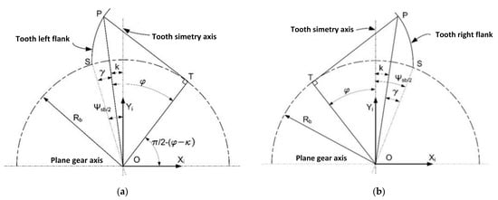
Figure 16.
The involute model: (a) left flank; (b) right flank [28].
For the involute profile of the tooth’s left flank, the reference systems are defined as follows:
- -
- xy—system solidary with the pinion cutter;
- -
- xiyi—system solidary with “i-th” flank tooth of the tool, originally overlapped on xy.
Starting from the definition of the involute,
and transforming and replacing, the equation of the left involute flank was obtained as the semi-arc of the full tooth on the base circle and of radius Rb, respectively.
where z is the teeth number of the plane wheel and m is the normal module identical to the frontal module (for straight teeth). Similarly, the equation of the right involute flank was obtained.
Finally, the circular flank, defined as the upper arch of the tooth on the outer circle of the teeth and delimited by the left flank and the right flank, is described by the equations:
with θ as a variable parameter, where θ ∈ [0, (Ve)d] for the right flank and θ ∈ [(Ve)s, 0] for the left flank, respectively.
Therefore, the analytical model of teeth that simultaneously detach chips can be written as a set of equations:
where Xi and Yi are replaced with the tooth apex profile equations to describe the left flank, the right flank, and the tooth apex, respectively.
The worm generation process involves a rolling motion between the centrodes of the generated worm and those of the pinion cutter. If Φ1 and Φ2 are the angular parameters of the tool motion, respectively, of the worm motion around its own axes, then the rolling condition between the two centrodes has the expression:
where pax is the axial pitch of the generated worm (with a single thread) and Rd is the radius of the tool rolling circle:
It was considered that the transverse feed of the pinion cutter was proportional to the rotation angle of the tool, having the ratio λ. Therefore, if A12-0 represents the initial distance between the axis of the generated worm and the axis of the tool, then, at a given moment, the real distance between the two axes becomes:
The distance A12-0 corresponds to the tangency between the outer cylinder of the generated worm (of radius re) and the outer circle of the tool (of radius Re), which is as follows:
To express the kinematics of the worm generation process, it is necessary to define the following reference systems:
- -
- xy, which represents the global system of the tool, originating in the initial position of the tool axis;
- -
- x0y0—the global system of the worm, having its origin on the axis of the worm;
- -
- XY—the local mobile system attached to the tool;
- -
- X0Y0—the local mobile system, attached to the generated worm and with the X0-axis coinciding with the worm axis.
The absolute motion matrix equation is as follows:
for the tool, and
for the worm.
In Equation (21), ω3 is the known rotation matrix around the Z-axis of the coordinates system. The relative position between the two global systems is described by the equation:
The matrix equation that expresses the generation motion (the relative motion between the two mobile systems) results from Equations (21)–(23):
3.3.2. Graphical Modeling
The graphic solution for determining the shape and cumulative size of the chip areas detached from the pinion cutter teeth is developed for the case of generating a globoid worm with an involute profile of module m = 5 mm and outer diameter 2 ∙ re = 34 mm, with a pinion cutter tool with z = 20 teeth. The workpiece from which the worm was obtained had a cylinder shape with a diameter of 34 mm.
To simulate the motion of the tool and workpiece, rotation steps of the workpiece of 45° were considered. According to the rolling condition, this corresponds to a rotation angle of the pinion cutter,
for each axial section analyzed, and a translation of the measurement plane located on the respective section with
For the processing of a globoid worm (Figure 17) with a pinion cutter (Figure 18), the graph of the variation in detached chips section, measured in the 8 semi-planes, was drawn.
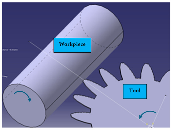
Figure 17.
Turning of a globoid worm with the pinion cutter. Positioning the tool to start machining [28].
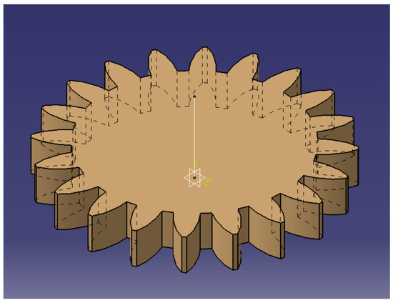
Figure 18.
Pinion cutter (z = 20 teeth, m = 5 mm) [28].
Finally, the shape and area of the detached chips were obtained by comparing the current surface with the previously measured surface in the same axial section. The sequences of chip formation in a semi-plane are presented in Figure 19 (the successive positions of the tool relative to the workpiece axis are presented in the figure).
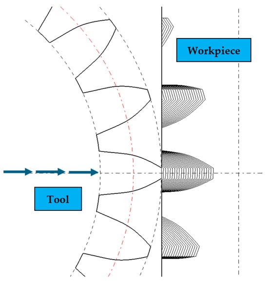
Figure 19.
Chip formation sequences: hollow formation—globoid worm [28].
For simplification, without very large deviations, one can choose, for approximating the distribution function of the chip section during the processing of the globoid worm, a much more accessible function of the shape, namely a function of the 1st degree (see also Figure 20):
where p1 and p2 mean the coefficients from the known straight-line equation.
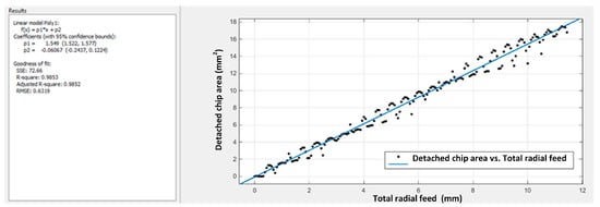
Figure 20.
Polynomial function of 1st degree to approximate the section of detached chips when processing a globoid worm (z = 20 teeth, m = 5) [25].
In Figure 20, the feed of the pinion cutter is represented on the abscissa, starting from the contact with the workpiece. The measured area of the chips corresponds to a feed of 0.0625 mm during the rotation of the workpiece by 45°.
If the area of the formed chips is required to be approximately 2 mm2, and the imposed value of the chip section is much lower than the values measured under the conditions of a cutter feed of 0.5 mm/workpiece rotation, the number of rotations performed by the workpiece increases from 23 to 744/8 = 93 rotations.
However, the machine’s stress drops significantly compared to the first case when the formed chips had areas between 0 and 17 mm2 (Figure 21).
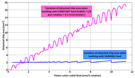
Figure 21.
Uniformization of the detached chip section during the turning of a globoid worm (z = 20 teeth, m = 5 mm) [25].
Unlike the situations presented previously, in the case of globoid worm turning, it is no longer possible to act discretely on the feed. Thus, in the globoid worm, which was obtained by turning, the cutter is actuated in correlation with the rotational motion of the workpiece. Therefore, the variation law no longer allows a displacement or angle change/double stroke, but a feed/rotation value or a per-rotation fraction.
Given the fact that measurement was carried out with a 45° angular step, the feed on each octave of the workpiece rotation was calculated. Thus, for each relative position of the tool and workpiece, the two models of the tool and workpiece overlap. The chip was detached from the workpiece and the area of the remaining workpiece was measured.
In conclusion, the chip section area formed when turning a globoid worm using a pinion cutter can be controlled and maintained at imposed values by controlling the feed of the cutting tool. This is possible if the analytical law giving the chip area variation during simulated machining in a graphical environment is known.
4. Technical Solution for Method Implementation
In the case of current toothing equipment, the gear pair located on the machine table ensures both the table translation (motion II) and plate rotation (motion III), as shown in Figure 22, so that the rolling condition for obtaining involute teeth is realized according to part’s number of teeth and its module.
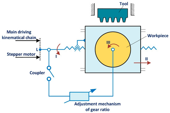
Figure 22.
Simplified kinematical schema for the driving chain of the part table and rotating plate on the slotting machine.
To implement the method for increasing the efficiency of the previously presented toothing process, the need to adapt the technological equipment must be considered so that the rotational and/or translational motions of the workpiece and the machine table should be controlled in order to vary the rolling motion speed.
Two alternatives for driving the machine table can be approached, which are different from the current mode (equal size steps, leading to the obtaining of detached chips with time-dependent variable sections).
The first alternative consists of actuating the machine table using an electric motor coupled to the connection point L between the mechanism located on the machine table and the classical actuation circuit (with which the kinematic communication will be interrupted). The advantage of this alternative lies in the fact that only one motor and its control circuit are used. Also, the tool vs. part rolling condition is preserved by means of the rigid connection between the two motions through the exchangeable gear pair.
This alternative, however, has the disadvantage that it requires a more powerful electric motor, which should be able to drive the entire mechanism of the table in motion.
The use of a motor, connected in this manner, ensures compliance with the rolling condition by using the wheels of the adjustment mechanisms used in the case of classical machining.
The second alternative consists of the use of two electric motors that generate separate and correlated motions I, (II), and III, respectively. Although the disadvantage would be the need to use two electric motors, with two control circuits, these motors can be smaller and implicitly have a lower purchase cost. Also, these motors, since they are actuated separately, can make the necessary division motion much easier during the workpiece machining.
After a trade-off, we propose, in what follows, the application of the first alternative.
To substitute the classic drive of the workpiece table and plate with an electric motor, the driving system must be chosen, and the set-up must be dimensioned.
The choice and dimensioning of the set-up are imposed by the technological process that is carried out. In this case, the type of electric motor and the set-up are established taking into account the following aspects:
- -
- To be able to make frequent starts and stops, because the number of double strokes per minute made by the cutting tool is of the order of tens. On each double stroke, the motor must start, move, or rotate the table on a prescribed distance, and brake. At a speed of 30 double strokes/minute, the motor will have to make approximately 1800 starts/hour, which greatly limits the possibility of choosing the motor type.
- -
- To consider the order of magnitude of the power required for operation, investment and exploitation expenses, yield, energy consumption, and others.
Since the motor drive is intermittent, the speed is chosen so that the kinetic energy stored in the motor–machine system is minimal.
When choosing the type of motor for the electrical actuation of the mechanism, theoretically, we can choose from a variety of motors (asynchronous, synchronous, three-phase, single-phase) operated by frequency converters, continuous current motors, and stepper motors.
The large number of starts/stops excludes the possibility of choosing alternative current motors, where the maximum frequency of connection is of the order of hundreds per hour, leaving continuous current motors and stepper motors to be considered.
The option of choosing a stepper motor is therefore proposed as it allows discrete (incremental) angular displacements of its mobile part (the rotor). Moreover, the stepper motor can be programmed to stop at any of these positions, or intermediate positions, when commanded in micro-step mode. It can also synchronize with the command pulses, operating without slippage and allowing sudden starts and stops without loss of steps and at adjustable speeds within very wide limits. In addition, if the sizing is carried out correctly and the specifications are respected, the stepper motor does not need feedback sensors, being able to work in an open loop, thus simplifying the electrical drive scheme. The motion of the motor is enacted with each received command pulse, performing point-by-point positioning. The values of plate displacements having to be made for each tool’s double stroke are introduced into the system using specialized software installed on a computer connected to the control panel of the electric motor.
To validate the proposed solution of controlled actuation of a slotting machine table, an experimental stand was designed and executed (Figure 23) on which controlled motions of the mechanism for translation according to a given law could be obtained.
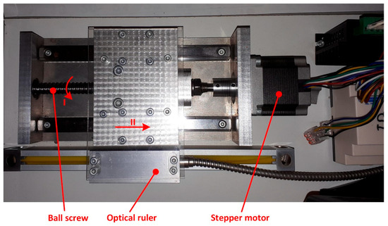
Figure 23.
Experimental set-up for controlling motions II, when using a stepper motor [25].
The experimental set-up contains a translation mechanism actuated by a stepper motor, which is controlled with a DM542H driver (Figure 24), whose settings allow the obtaining of micro steps up to 360°/25,600 = 0°0′50.63″, so less than a 1′ arc. The driver was powered with a direct voltage obtained from a 220 V AC source/24 V DC, able to provide the required current, so that there is no loss of steps at the motor axis, with bad influences on the accuracy of command execution.
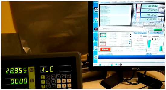
Figure 24.
The command and control of linear motions [25].
The driving was controlled through the Mach3 software version 3.043.066 installed on a computer that was connected to the stand through the parallel interface (Figure 25).
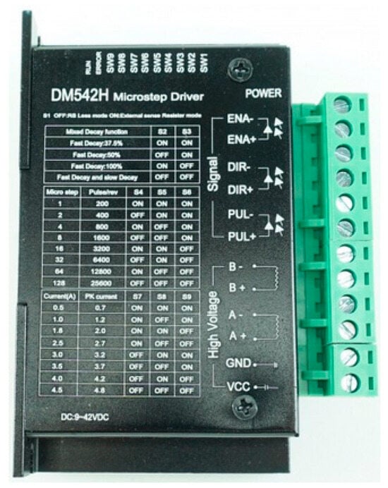
Figure 25.
Stepper motor driver [25].
The confirmation of displacement accuracy was obtained by actual measurement using a type RV 1846 optical ruler with a resolution of 5 μm mechanically fixed to the movable element of the mechanism and connected to a reading system (see Figure 23). In addition, to make the axial clearance as small as possible, the movable element was connected to the stepper motor shaft by means of a ball screw, with a pitch of 4 mm.
These components allowed for great motion accuracy, with a 10 μm gear clearance when changing the direction of motion. As the motion is in one direction during the generation of a tooth gap, this clearance can be picked up by the positioning motions.
The tests we carried out showed the feasibility of applying the proposed solution in order to obtain the table motion (motion II, Figure 22) according to a law resulting from the application of the method of smoothing the detached chip area.
For this purpose, successive intermittent motions of the table were measured (with an optical ruler) and compared with the necessary/imposed ones. The results confirmed the coincidence between these values (with the maximum error of 10 μm).
5. Conclusions
Taking into account the increasing importance of sustainability principles in manufacturing activity, this work presents an original method for improving the energy efficiency of toothing processes.
The method is exemplified in the case of machining involute cylindrical gears with straight teeth by using tools such as the rack tool and the pinion cutter, as well as for machining involute worms with a pinion cutter.
The principle of the method is, however, generally applicable to the processing of any type of tooth and consists of equalizing the magnitude of the cutting force by equalizing the area of the successively detached chip. In order to achieve this result, the modeling of the detached chips area, in the case of conventional processing, with constant feed in the rolling motion, must be carried out first. In the case of the proposed method, this modeling was carried out graphically by means of the CATIA V5R21 dedicated software. Based on the obtained model, the variation law of the feed in the rolling motion is then determined, with the help of specially designed MatLab applications, which, if respected, leads to the detachment of successive chips of quasi-constant area, the size of which is set a priori, depending on technical–economic criteria.
The addressed case studies validated the feasibility of the method application. The work also presents a solution for the practical implementation of the method on conventional toothing machines.
Future research will focus on the application of the method to the processing of other types of teeth (for example, the tooth of involute gears with inclined teeth), or the use of other toothing tools (for example, the worm-milling tool).
Author Contributions
Conceptualization, G.R.F.; methodology, G.R.F. and M.B.; software, M.B. and G.R.F.; validation, M.B.; formal analysis, F.S.; investigation, G.R.F.; resources, M.B.; writing—original draft preparation, G.R.F.; writing—review and editing, F.S.; visualization, F.S.; supervision, G.R.F. All authors have read and agreed to the published version of the manuscript.
Funding
This research received no external funding.
Institutional Review Board Statement
Not applicable.
Informed Consent Statement
Not applicable.
Data Availability Statement
The data is available at: https://opac.ugal.ro/cgi-bin/koha/opac-detail.pl?biblionumber=47921&query_desc=kw%2Cwrdl%3A%20bordeanu (accessed on 11 October 2024).
Conflicts of Interest
The authors declare no conflicts of interest.
References
- Gutowski, T.; Dahmus, J.; Thiriez, A. Electrical Energy Requirements for Manufacturing Processes. In Proceedings of the 13th CIRP International Conference of Life Cycle Engineering, Lueven, Belgium, 31 May–2 June 2006. [Google Scholar]
- Zhao, G.Y.; Liu, Z.Y.; He, Y.; Cao, H.J.; Guo, Y.B. Energy consumption in machining: Classification, prediction, and reduction strategy. Energy 2017, 133, 142–157. [Google Scholar]
- Cai, W.; Wang, L.; Li, L.; Xie, J.; Jia, S.; Zhang, X.; Jiang, Z.; Lai, K. A review on methods of energy performance improvement towards sustainable manufacturing from perspectives of energy monitoring, evaluation, optimization and benchmarking. Renew. Sustain. Energy Rev. 2022, 159, 112227. [Google Scholar]
- Zhou, G.; Lu, Q.; Xiao, Z.; Zhou, C.; Tian, C. Cutting parameter optimization for machining operations considering carbon emissions. J. Clean. Prod. 2019, 208, 937–950. [Google Scholar]
- Hu, L.; Tang, R.; Cai, W.; Feng, Y.; Ma, X. Optimisation of cutting parameters for improving energy efficiency in machining process. Robot. Comput. Integr. Manuf. 2019, 59, 406–416. [Google Scholar] [CrossRef]
- Velchev, S.; Kolev, I.; Ivanov, K.; Gechevski, S. Empirical models for specific energy consumption and optimization of cutting parameters for minimizing energy consumption during turning. J. Clean. Prod. 2014, 80, 139–149. [Google Scholar] [CrossRef]
- Hanafi, I.; Khamlichi, A.; Mata Cabrera, F.; Almansa, E.; Jabbouri, A. Optimization of cutting conditions for sustainable machining of PEEK-CF30 using TiN tools. J. Clean. Prod. 2012, 33, 1–9. [Google Scholar] [CrossRef]
- Bagaber, S.A.; Yusoff, A.R. Multi-objective optimization of cutting parameters to minimize power consumption in dry turning of stainless steel 316. J. Clean. Prod. 2017, 157, 30–46. [Google Scholar]
- Chen, X.; Li, C.; Tang, Y.; Li, L.; Li, H. Energy efficient cutting parameter optimization. Front. Mech. Eng. 2021, 16, 221–248. [Google Scholar] [CrossRef]
- Dooner, D.B. Kinematic Geometry of Gearing, 2nd ed.; Wiley: West Sussex, UK, 2012. [Google Scholar]
- Radzevich, S.P. Theory of Gearing. Kinematics, Geometry and Synthesis, 2nd ed.; CRC Press: Boca Raton, FL, USA, 2018. [Google Scholar]
- Gupta, K.; Kumar, N.J.; Laubscher, R. Advanced Gear Manufacturing and Finishing, 1st ed.; Elsevier Inc.: Amsterdam, The Netherlands, 2017. [Google Scholar]
- Stephenson, D.A.; Agapiou, J.S. Metal Cutting Theory and Practice, 3rd ed.; CRC Press: Boca Raton, FL, USA, 2018; p. 947. [Google Scholar]
- Fu, H.J.; DeVor, R.E.; Kapoor, S.G. A mechanistic model for the prediction of the force system in face milling operations. J. Eng. Ind. 1984, 106, 81–88. [Google Scholar] [CrossRef]
- Kim, H.S.; Ehmann, K.F. A cutting force model for face milling operations. Int. J. Mach. Tools Manufact. 1991, 33, 651–673. [Google Scholar] [CrossRef]
- Otalora Ortega, H.; Aristimuno Osoro, P.; Arazola Ariola, P. Uncut chip geometry determination for cutting forces prediction in ortogonal turn-milling operations considering the tool profile and eccentricity. Int. J. Mech. Sci. 2021, 198, 106351. [Google Scholar] [CrossRef]
- Azvar, M.; Katz, A.; Van Dorp, J.; Erkorkmaz, K. Chip geometry and cutting force prediction in gear hobbing. CIRP Ann. Manuf. Technol. 2021, 70, 95–98. [Google Scholar] [CrossRef]
- Sutherland, J.W.; Salisbury, E.J.; Hoge, F.W. Model for the cutting force system in the gear broaching process. Int. J. Mach. Tools Manufact. 1997, 37, 1409–1421. [Google Scholar] [CrossRef]
- Dima, M.; Oancea, N.; Teodor, V. Modelarea Schemelor de Așchiere la Danturare; Editura Cermi: Iasi, Romania, 2007. [Google Scholar]
- Dima, M.; Oancea, N. Constructive modification of the energeticaly improvement of the toothing process. Rom. J. Tech. Sci. Appl. Mech. 2004, 49, 237–241. [Google Scholar]
- Petre, I.M.; Gavrus, C. Influence of the cutting force upon machining process efficiency. Mater. Today Proc. 2023, 72, 586–593. [Google Scholar] [CrossRef]
- CATIA V5 Fundamentals Guide, Dassault Systemes, Version 5, Release 19. Available online: http://yvonet.florent.free.fr/SERVEUR/COURS%20CATIA/EDU_CAT_EN_V5F_FB_V5R19.pdf (accessed on 1 February 2020).
- Oancea, N. Generarea suprafețelor prin înfășurare. Complemente de teoria înfășurărilor; Editura Fundatiei Universitare Dunarea de Jos: Galați, Romania, 2004. [Google Scholar]
- Matlab Guide—The Language of Technical Computing; Version 7; MathWorks Inc.: Natick, MA, USA, 2005; Available online: https://www.mn.uio.no/astro/english/services/it/help/mathematics/matlab/getstart.pdf (accessed on 1 November 2023).
- Bordeanu, M. Energy Optimization of Toothing Processes by Changing the Kinematic Parameters of the Rolling Motion. Ph.D. Thesis, Dunarea de Jos University of Galati, Galați, Romania, 2021. [Google Scholar]
- Bordeanu, M.; Frumuşanu, G.R.; Oancea, N. Graphical modeling of gear tooth generating process with rack-shaped tool aiming constant area of detached chips. Proc. Manuf. Syst. 2018, 13, 63–68. [Google Scholar]
- Bordeanu, M.; Frumuşanu, G.R.; Oancea, N. Analytical and graphical modelling of the cutting scheme when generating with a pinion cutter. IOP Conf. Ser. Mater. Sci. Eng. 2019, 591, 012042. [Google Scholar] [CrossRef]
- Bordeanu, M.; Frumuşanu, G.R.; Oancea, N. Algorithms for modelling the load of teeth from pinion cutter tool used at worms machining. IOP Conf. Ser. Mater. Sci. Eng. 2019, 564, 012005. [Google Scholar] [CrossRef]
Disclaimer/Publisher’s Note: The statements, opinions and data contained in all publications are solely those of the individual author(s) and contributor(s) and not of MDPI and/or the editor(s). MDPI and/or the editor(s) disclaim responsibility for any injury to people or property resulting from any ideas, methods, instructions or products referred to in the content. |
© 2024 by the authors. Licensee MDPI, Basel, Switzerland. This article is an open access article distributed under the terms and conditions of the Creative Commons Attribution (CC BY) license (https://creativecommons.org/licenses/by/4.0/).