Abstract
The purpose of this work is to test the effectiveness of strengthening timber structures by means of composite bars. This article presents the results of preliminary tests carried out on solid beams made of fir wood. The test specimens, which are classified as strength class C24, had dimensions of 7 × 17 × 330 cm. Beams were reinforced with 8 mm diameter basalt fiber-reinforced polymer (BFRP) bars. The bars were glued into grooved channels along the bottom surface. Epoxy resin was used as an adhesive. The strength tests were conducted in accordance with the requirements of EN 408+A1:2012. The four-point bending scheme was adopted. The tests were conducted in the following two series: unreinforced beams (A) and beams reinforced with composites (B). Five elements were tested in each series. The reinforcement resulted in an average increase in the bending moment value of 8.41%. The deflection value at failure increased by 19.77%. The work also includes an analysis of the failure mode and a ductility analysis. Further tests should be carried out using a higher reinforcement ratio. A higher reinforcement ratio should make the presented reinforcement configuration more effective.
Keywords:
basalt fibers; bars; composites; ductility; load-bearing capacity; reinforcement; wood structures 1. Introduction
There is considerable interest among engineers in the subject of strengthening timber structures. Wood is a natural material with a long history of use in construction. However, it is susceptible to a number of destructive biological processes and fire [1]. There are ways to protect wood from these threats [2]. These measures contribute to improving the durability of timber structures but do not result in an overall increase in their strength parameters. Consequently, researchers are exploring methods to reinforce timber structures. Fiber-reinforced polymer (FRP) composite materials are becoming an increasingly popular choice for this purpose. The key benefits of these materials are their low dead weight, corrosion resistance, ease of material processing, high tensile strength and fatigue resistance. These characteristics are crucial when it comes to reinforcing the structural elements of a historic building or any other building in which it is important to preserve the naturalness of the wood and the aesthetics of the building. The most commonly used composite reinforcement materials are sheets, strips, and rods. Further details on the use of composites for reinforcement can be found in the following works [3,4,5].
Raftery and Kelly used 12 mm diameter basalt bars for reinforcement [6]. Test results proved the reinforcement effectiveness. A 10% and 23% increase in stiffness and moment capacity in comparison to unreinforced beams was obtained, respectively. The authors concluded that basalt bars (BFRP) as reinforcement gave better results than glass bars (glass fiber-reinforced polymer).
Rajczyk and Jończyk [7] conducted a four-point bending test on small-scale glue-laminated timber beams reinforced with BFRP bars. The bar diameters were 7 and 9 mm. The study authors applied reinforcement in the compression and tension zones in a variety of configurations. In sections in which the diameter of the bars in the two zones differed, the beams demonstrated the most favorable performance.
Paper [8] outlines a method of poststressing with glass fiber-reinforced plastic rods and reinforcing with carbon sheets. To simulate biological failure, holes were drilled inside the element. Tests were conducted on softwood beams made from Japanese cedar. A comparison of the results for the reinforced elements in relation to the beams in the control group shows an increase in the bending moments for the three tested groups of 4.3%, 3.5%, and 9.5%.
Yusof and Saleh [9] used fiberglass for reinforcement purposes. They noted a 20–30% increase in the load-carrying capacity. The GFRP-reinforced beams demonstrated an improvement in stiffness of between 24% and 60%. The results include beams reinforced using the following two methods: one bar (three elements) and two bars (three elements).
Article [10] presents a comparative analysis of the performance of poststressed composite bars and steel bars. The use of poststressed basalt bars to reinforce glulam beams proved to be a successful technique. The load capacity of the elements increased by 31.12%, the stiffness increased by 9.91%, and the ductility increased by 9.87%.
Garcia et al. conducted tests on basalt- and carbon-reinforced pine timber beams [11]. The reinforcement was provided in the form of fabrics bonded to the external faces. Increases in both the load-bearing capacity and stiffness in comparison to unreinforced beams were obtained.
Svecova et al. [12,13] analyzed the behavior of timber beams reinforced with fiberglass rods. One study demonstrated an increase in bending capacity of between 18% and 46%. The degree of reinforcement of the beams ranged from 0.27% to 0.82%.
A study published by Borri et al. [14] indicates that composite sheets are a more beneficial solution than composite bars. However, the author highlights that the reinforcing bars placed inside the beam section are not visible, which is a significant benefit.
The reinforcement of solid timber beams made of basalt bars is not studied as often as glass or carbon bars. The following section of this paper will present the results of the authors’ research. The aim of this research is to check the relevance of the reinforcement used and to analyze the performance of the reinforced beams.
2. Materials and Methods
2.1. Materials
2.1.1. Wood
The test was carried out on full-sized beams made of fir wood. The general characteristics of structural wood (fir) were presented in [15,16]. The grade class was C24, according to the PN-EN 338 standard [17]. The material was purchased from Scanwood Drewno Skandynawskie Sp. z o.o. (Mikolow, Poland) [18]. The cross-section of the beams was 70 × 170 mm. The total length of the elements was 3.30 m. The moisture content of timber was measured on the test day using a WDR-100 electrofusion moisture meter from TANEL Elektronika i Informatyka Spółka Jawna (Gliwice, Poland) [19]. The mean value of moisture content was 13.7%. The tests were carried out in two series of five elements each. The characteristics of the unreinforced beams are given in Table 1.

Table 1.
Basic mechanical parameters of wood (A-series).
Wooden elements were properly prepared before reinforcing and testing. Grooves were cut from the underside using a milling machine. The grooves had dimensions approximately equal to 12 × 12 × 2820 mm. These dimensions were then verified with a caliper, and the grooves were cleaned. The grooves prepared in this way were ready for the bars to be inserted.
2.1.2. Basalt Fiber-Reinforced Polymer (BFRP) Bars
As a reinforcement, basalt fiber-reinforced polymer bars with a diameter of 8 mm were used. The composite material for this study was purchased from Tech-Solutions (Skarżysko-Kamienna, Poland) [20]. The reinforcement was transported in coils and then cut to the required length. The 2.80 m-long bars were glued into the prepared grooves. According to the manufacturer’s website, the tensile strength of the composite bar of the used diameter is 41.32 kN, and the modulus of elasticity of these bars is 85–95 GPa [20,21]. Figure 1 shows a view of the composite reinforcement.
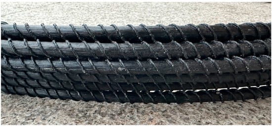
Figure 1.
BFRP bars.
2.1.3. Epoxy Resin
The system adhesive, S&P Resin 55 HP, was purchased from S&P Polska Sp. z o.o. (Malbrok, Poland) [22] and used to properly bond the reinforcement to the wood. This is a two-component, solvent-free adhesive based on epoxy resin with an amine hardener. The ratio of the mixed components is 2:1. According to the manufacturer’s data [23], the modulus of elasticity of adhesive was 3200 MPa. The compressive strength and density were 100 MPa and 1200–1300 kg/m3, respectively.
2.2. Methods
The research was carried out at the Laboratory for the Strength of Materials of the Kielce University of Technology. The aim of the preliminary study is to verify the effectiveness of reinforcing wooden beams with basalt bars glued into near-surface grooves. The scope of the research included the preparation of two five-element test series, designated as A and B.
Series A were unreinforced reference elements. Series B were beams reinforced with two BFRP bars glued into the grooves in the tension zone. The reinforcement ratio of the beams was 0.84%. Figure 2 shows the cross-sections of both series.
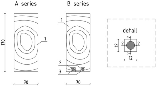
Figure 2.
View of the tested beams in cross-section (1—wooden beam, 2—composite bar, 3—adhesive).
The bending was carried out according to the specifications of the standard [23], i.e., four-point static bending tests. The load was applied with the use of Instron hydraulic cylinders. The beams were symmetrically loaded with two concentrated forces, defined as F1 and F2. The distance between the axes of the concentrated forces was 1.02 m, which is equivalent to six times the height of the beam cross-section. The distance between the support axis and the axis of the nearest concentrated force was also 1.02 m. A diagram of the test stand is shown in Figure 3. Dimensions are given in millimeters. The loading rate of an actuator was set based on the recommendations of the standard [23], which was 7 mm/min. The deflection of the timber beams was measured at mid-span using an inductive sensor manufactured by Hottinger Baldwin Messtechnik placed on top of the beam. A wooden safety device was placed in the axes of the supports to stabilize the test piece against displacement from the bending surface.
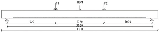
Figure 3.
Test stand scheme.
During testing, the load value in both actuators [kN], the displacement of the actuators [mm], and the test time [s] were recorded continuously. Data were recorded at a frequency of 5 Hz. A view of the test stand is shown in Figure 4. A cross-section and an underside view of the research elements are shown in Figure 5.
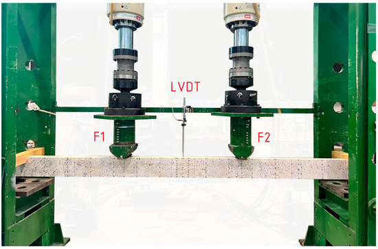
Figure 4.
View of the test stand.
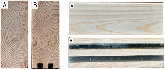
Figure 5.
Views of unreinforced (A) and reinforced (B) testing elements.
3. Results
The results of the bending tests are presented in terms of bending capacity, ductility, and failure mode.
3.1. Load-Bearing Capacity
The bending tests are illustrated in the graphs, which show the loading force and deflection of the beam at mid-span. Figure 6 illustrates the force–deflection relationship for unreinforced beams. The results for reinforced beams are presented in Figure 7.
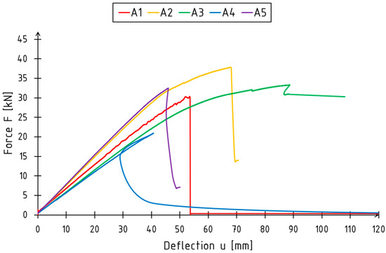
Figure 6.
Force–deflection relationship for unreinforced beams (A-series).
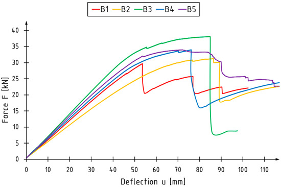
Figure 7.
Force–deflection relationship for strengthened beams (B-series).
Figure 6 illustrates a nearly linear correlation between load and deflection for unreinforced beams from the beginning to the end of the test. Some nonlinearity, however, is visible for the A2 and A3 beams in the final phase of the test. This was caused by the plasticization of the compressive zone. Generally, fractured wood resulted in a significant drop in loading force—greater than 60% of the maximum value. That drop was treated as the failure moment of the beam.
Figure 7 shows the smaller decreases occurring when the timber breaks in the tension zone and the larger decreases occurring at failure. The B-series beams demonstrate a more distinct transition into the plastic working range.
Table 2 and Table 3 present the values for the failure force, bending moments, and deflection of each beam.
Table 2.
Results of beam tests—Series A.
Table 3.
Results of beam tests—Series B.
A comparison of the average deflection and maximum loading force values are shown in the graphs below (Figure 8).
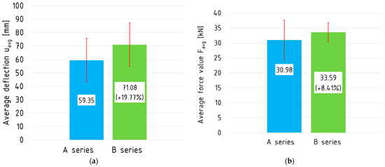
Figure 8.
(a) Average deflection and (b) maximum loading force values.
3.2. Ductility
The ductility of a material is defined as its susceptibility to deformation without affecting its load-bearing capacity. The following analysis is carried out on the basis of [24]. To evaluate the influence of reinforcement on the bending ductility, four different indices were used. Three of them can be classified as deflection or deformation indices, whereas one is based on energy absorption. Energy absorption values were evaluated using the load versus deflection curves.
The ductility expressed by the index D, which is an analysis of the deflection of reinforced beams relative to unreinforced beams, is represented as a ratio, as follows:
where uFmax,w is the deflection at maximum load for the reinforced beam, and uFmax,nw is the deflection at maximum load for the unreinforced beam.
The deflection ductility index and are expressed as a ratio of the respective deflection values, as follows:
where uu is the value of maximum deflection while keeping the load-bearing capacity, ue is the value of deflection at the proportional limit, and uy is the value of the deflection at the moment of yielding.
The ductility index µE was calculated based on the values of total energy and elastic energy:
where Wtot is the total energy value, and We is the elastic energy value.
The load–deflection relationship curve was approximated using a fifth-degree polynomial. The elastic limit is defined as the point at which the trend line of the relevant graph section intersects with the polynomial function. In order to ascertain the yield stress, two further functions were defined. The first function is linear and parallel to the x-axis, passing through the point of maximum load. The second function is also linear, inclined at an angle determined from the slope of the linear elastic part of the graph in relation to the first function. The yield stress was identified as the point of intersection between the calculated straight line and the trend line. The energy values from the origin to the characteristic points were calculated using labeled integrals. A detailed description of the evaluation method can be found in [24].
The results for the various methods of calculating the ductility index are shown in Table 4. Statistical analyses of the deflection values, estimated surface areas, and ductility indices are presented in Table 5 and Table 6. The numbers in brackets represent the percentage change from the values in Table 5.
Table 4.
Ductility analysis results.
Table 5.
Statistical analysis of ductility for A-series beams.
Table 6.
Statistical analysis of ductility for B-series beams.
3.3. Failure Modes
The typical failure mode of unreinforced beams is presented in Figure 9. Beams failed due to the wood fracturing in the tensile zone due to exceeding the tensile strength of wood parallel to the grain. In all cases, cracking was initiated in the mid-span of the beams, between the loading axes. Given the natural nature of wood and the presence of flaws, the magnitude and path of the cracks differ between the beams.
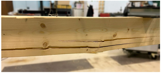
Figure 9.
Failure of the A-series beams.
Similarly, the reinforced beams were damaged by a comparable mechanism (A in Figure 10). Cracks occurred in all beams, mainly in the tension zone. There were also cases of the crushing of the wood in the compression zone (C in Figure 10). These were observed in the middle of the span. In the reinforced beams, adhesive crushing was noted along the entire length of the elements in an irregular way. Furthermore, tensile bar extraction (B in Figure 10) was also observed. The bars had been bent, rather than broken. The failure of the beams (B2) and the increasing internal forces (B3 and B4) were the root causes of the issue. The failure modes of the B-series beams are illustrated in Figure 10.
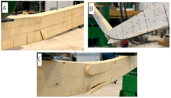
Figure 10.
Failure of the B-series beams (A—fracture of wood in tensile zone; B—fracture of wood in tensile zone followed by the debonding of BFRP reinforcement; C—crushing of wood in compressive zone and fracture of wood near the knot in the tensile zone).
4. Discussion
4.1. Load-Bearing Capacity
The force–deflection relation diagrams demonstrate the typical behavior of unreinforced beams. These characteristics are evident in the excursions that occur at the point of failure. This behavior of timber members has been described in numerous publications, including [25,26].
The diagrams for reinforced beams demonstrate the failure process of the beams in a clear and visible manner, indicating the moments of the occurrence of cracking and complete failure. Typically, the failure of unreinforced beams was caused by a single crack and, corresponding to its formation, a drop in loading force, while for the reinforced beams, multiple drops were recorded—failure in steps. Each drop in loading force can be followed by a strengthening process. The behavior of reinforced beams is less predictable in comparison to unreinforced ones. Further examples of this type of force–deflection diagram can be found in publications [12,27,28].
As expected, the reinforced elements are capable of bearing higher loads (kN) with increased deflection (mm). The deflection of the reinforced beams increased by 19.77% in comparison to that of the reference beams. The average bending moment has increased by 8.41%. The standard deviation of the values of Fmax and d decreased for the strengthened beams.
4.2. Ductility
For all applied ductility indices, an increase in ductility was obtained. The greatest increase in bending ductility was obtained for the D index. This means that the reinforcement significantly shifted the moment of failure of reinforced beams in comparison to unreinforced ones.
Obtained increases in ductility were lower than in [29,30,31], in which glass profiles or sheets were used as a reinforcement. Shekarchi et al. [29] obtained a significant increase in deflection ductility and energy absorption for the timber beams strengthened with glass fiber-reinforced polymer (GFRP) profiles. Deflection ductility increases were between 25% and 79% and were dependent on the reinforcement layout. Nadir, et al. [30] analyzed the bending ductility of glue-laminated timber beams reinforced with GFRP sheets. The reinforcement ratio was equal to 2.5 and 5% for one and two layers of reinforcement, respectively. A 44.37% to 46.36% increase in ductility was achieved in comparison to that of unreinforced beams. As stated by Bhat et al. in [31], the ductility increases with the increase in the reinforcement ratio. Therefore, further tests should include bars with greater diameters.
4.3. Failure Modes
The main cause of the failure of the A-series beams was the fracture of the wood in the tensile zone. Cracking occurred, as predicted, between the axes of applied forces. Due to the nature of the structural material, this is a typical occurrence [32].
In the case of reinforced beams, the provided low reinforcement ratio was not sufficient to prevent the wood from cracking in the tensile zone. The cracking of wood resulted in damage to the bond line and finally in the debonding of the FRP material. This may suggest that, for the reinforcement of tensile zones, it would be more suitable to use a reinforcement that covers the external surface of wood and bond natural flaws. For two tested beams, fracture and debonding were followed by the crushing of the wood in the compressive zone at the mid-span of the element, which was probably due to the reduction of cross-section height. Similar failure mechanisms have been reported in papers [33,34].
4.4. Numerical Analysis
A numerical investigation was performed using the Abaqus 2017 software. The main assumptions regarding the preparation of simulations were adapted from [35,36,37]. A selection of them is provided here.
Wood, epoxy resin, and composite bars were modeled as three-dimensional deformable bodies. Steel guide plates were modeled as analytical rigid shells. Linear, perfectly plastic material models were assumed for all materials used. Properties were taken from Table 1 and [17,20,21,22]. We assumed 11.25 GPa, 35 MPa, and 0.3 for Young’s modulus, bending strength, and Poisson’s ratio for wood, respectively. We assumed 85 GPa, 820 MPa, and 0.3 for Young’s modulus, tensile strength, and Poisson’s ratio for BFRP, respectively. We assumed 3.2 GPa, 85 MPa, and 0.3 for Young’s modulus, bending strength, and Poisson’s ratio for epoxy resin, respectively. A perfect connection between epoxy and wood was created using “tie” constraints. Composite bars were embedded into the glue regions. “Hard Contact” for normal behavior and a friction coefficient equal to 0.3 for tangential behavior were used for interaction properties. The analysis was performed within a static range. Loading was conducted by the displacement of the loading plate located on the upper surface of the beam. Guide plate was allowed to move along the y-axis (vertical displacement) and rotate along the x-axis. For the support only the rotation along the x-axis was allowed. A view of the prepared assembled model is presented in Figure 11.
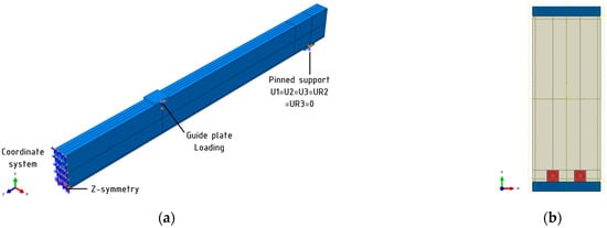
Figure 11.
Main assumptions for numerical analysis: (a) axonometric view; (b) cross-section of reinforced beam.
The results of the analysis are presented in Figure 12. Numerically obtained curves were plotted against experimental ones. For both unreinforced and reinforced specimens, the model predicts bending behavior well. Higher stiffness from the numerical model was obtained for the B-series. This phenomenon is probably due to differences between the actual and assumed properties of the reinforcing system. Further experimental studies are required in order to build a material model capable of capturing its fracture.
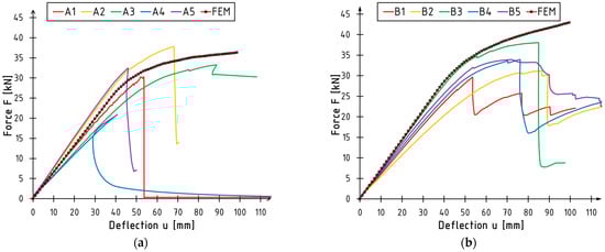
Figure 12.
Numerical versus experimental curves: (a) unreinforced beams; (b) reinforced beams.
5. Conclusions
This paper presents the results of tests on solid timber beams reinforced with basalt fiber-reinforced polymer (BFRP) bars. The reinforcement was glued into the section using an epoxy resin-based adhesive. The analysis examined the load-carrying capacity of the beams and their flexural strength, deflection, ductility, and failure form. This study showed that the applied reinforcement improved the strength parameters of the structure, thus confirming the validity of its execution. The summary is as follows:
- Reinforcement in the form of two 8 mm diameter basalt bars placed in the tension zone resulted in an 8.41% increase in the beam’s load-bearing capacity. In the reinforced beams, greater deflection was observed and increased by 19.77% on average. The test time (to failure of the element) in reinforced beams increased slightly.
- When analyzing the load capacity, the scatter of results for reinforced beams was smaller than for unreinforced beams. The opposite situation was true for analyzing the ductility of the timber elements.
- The largest percentage increase in ductility values was observed for the index based on the ratio of deflection values of reinforced to unreinforced beams. This value almost doubled. The other ductility indices increased by between 14% and 24%.
- The damage was influenced by tension and compression effects. In B-series beams, the reinforcement failed, with bar extraction and bond spalling. This is typical for this type of test and material.
It can be concluded that reinforcing timber beams with basalt bars is a promising way of strengthening solid timber beams. However, further research is necessary to make the use of reinforcements more effective. Considering the research so far has only been carried out on ten beams, testing a larger number of specimens would provide greater homogeneity in the results obtained. Due to the limitation of the number of elements tested, it would be beneficial to conduct a numerical analysis of the tested reinforcement.
To improve the parameters obtained, tests can be carried out using a larger bar diameter. The use of hybrid reinforcement is worth considering. The use of a composite sheet could prevent rod separation [38]. The authors are currently conducting further research into both of these methods for enhancing the effectiveness of the reinforcement.
Author Contributions
Conceptualization, P.G.K. and M.M.B.; methodology, P.G.K. and M.M.B.; formal analysis, M.M.B. and J.D.; investigation, M.M.B. and J.D.; data curation, M.M.B. and J.D.; writing—original draft preparation, J.D.; writing—review and editing, P.G.K., M.M.B. and J.D.; supervision, P.G.K. and M.M.B.; funding acquisition, P.G.K. All authors have read and agreed to the published version of the manuscript.
Funding
The tests were implemented thanks to the financial support of the Kielce University of Technology within the framework of the statutory work No. 02.0.20.00/1.02.001, SUBB. BKTK. 24.002.
Institutional Review Board Statement
Not applicable.
Informed Consent Statement
Not applicable.
Data Availability Statement
The original contributions presented in the study are included in the article, further inquiries can be directed to the corresponding author.
Acknowledgments
The authors would like to thank Paweł Tworzewski and Grzegorz Ordysiński for their help in carrying out the experimental research.
Conflicts of Interest
The authors declare no conflicts of interest.
References
- Żaboklicki, A. Rehabilitacja i Wzmacnianie Zabytkowych Konstrukcji Drewnianych; Wydawnictwo Politechniki Świętokrzyskiej: Kielce, Poland, 2013. [Google Scholar]
- Rudziński, L. Knstrukcje Drewniane. Naprawy, Wzmocnienia, Przykłady Obliczeń; Wydawnictwo Politechniki Świętokrzyskiej: Kielce, Poland, 2008. [Google Scholar]
- Rajczyk, M.; Jończyk, D. Przegląd metod wzmacniania konstrukcji drewnianych. Budownictwo 2011, 17, 146–160. [Google Scholar]
- André, A. Fibres for Strengthening of Timber Structures; Luleå Tekniska Universitet: Luleå, Sweden, 2006. [Google Scholar]
- Stanila, O.; Isopescu, D.; Hohan, R. Timber Elements: Traditional and Modern Strengthening Techniques. Bul. Institutului Politeh. Din Lasi Sect. Constr. Arhit. 2010, 56, 75. [Google Scholar]
- Raftery, G.M.; Kelly, F. Basalt FRP rods for reinforcement and repair of timber. Compos. Part B Eng. 2015, 70, 9–19. [Google Scholar] [CrossRef]
- Rajczyk, M.; Jończyk, D. Badania belek z drewna klejonego warstwowo wzmocnionych prętami bazaltowo-epoksydowymi. Zesz. Nauk. Politech. Częstochowskiej Bud. 2019, 174, 298–304. [Google Scholar] [CrossRef]
- Li, Y.-F.; Tsai, M.-J.; Wei, T.-F.; Wang, W.-C. A study on wood beams strengthened by FRP composite materials. Constr. Build. Mater. 2014, 62, 118–125. [Google Scholar] [CrossRef]
- Yusof, A.; Saleh, A.L. Flexural Strengthening of Timber Beams Using Glass Fibre Reinforced Polymer. EJSE 2010, 10, 45–56. [Google Scholar] [CrossRef]
- Wdowiak-Postulak, A. Numerical, theoretical and experimental models of the static performance of timber beams reinforced with steel, basalt and glass pre-stressed bars. Compos. Struct. 2023, 305, 116479. [Google Scholar] [CrossRef]
- De La Rosa García, P.; Escamilla, A.C.; Nieves González García, M. Bending reinforcement of timber beams with composite carbon fiber and basalt fiber materials. Compos. Part B Eng. 2013, 55, 528–536. [Google Scholar] [CrossRef]
- Gentile, C.; Svecova, D.; Rizkalla, S.H. Timber Beams Strengthened with GFRP Bars: Development and Applications. J. Compos. Constr. 2002, 6, 11–20. [Google Scholar] [CrossRef]
- Svecova, D.; Eden, R.J. Flexural and shear strengthening of timber beams using glass fibre reinforced polymer bars—An experimental investigation. Can. J. Civ. Eng. 2004, 31, 45–55. [Google Scholar] [CrossRef]
- Borri, A.; Corradi, M.; Grazini, A. A method for flexural reinforcement of old wood beams with CFRP materials. Compos. Part B Eng. 2005, 36, 143–153. [Google Scholar] [CrossRef]
- Bodig, J.; Goodman, J. Prediction of elastic parameters for wood. Wood Sci. 1973, 5, 249–264. [Google Scholar]
- Stefańczyk, B.; Budownictwo Ogólne Tom. Materiały i Wyroby Budowlane, Tom 1; Arkady: Warsaw, Poland, 2010. [Google Scholar]
- PN-EN 338:2016-06; Drewno Konstrukcyjne-Klasy Wytrzymałości. Polish Committee for Standardization: Warsaw, Poland, 2016.
- Scanwood Drewno Skandynawskie Sp. z o.o. Available online: https://www.scanwood.com.pl/ (accessed on 15 October 2024).
- TANEL Elektronika i Informatyka Spółka Jawna. Available online: http://www.tanel.com.pl/wilgotnosciomierz.php?kod_produktu=wrd100 (accessed on 15 October 2024).
- Tech Solutions. Available online: https://www.tech-sols.pl/kompozytowe-prety-zbrojeniowe (accessed on 20 February 2024).
- Basfiber. Available online: https://basfiber.com/properties/mechanical-properties (accessed on 20 February 2024).
- S&P Resin 55 HP—Karta Techniczna. Available online: https://www.sp-reinforcement.pl/sites/default/files/field_sup_dcmnt_file/2024/01/24/131247/resin55_hp_polska_ver20190523.pdf (accessed on 2 January 2024).
- PN-EN 408+A1:2012; Konstrukcje Drewniane. Drewno Konstrukcyjne Lite i Klejone Warstwowo. Oznaczanie Niektórych Właściwości Fizycznych i Mechanicznych. Polish Committee for Standardization: Warszawa, Poland, 2012.
- Bakalarz, M.M.; Kossakowski, P.G. Ductility and Stiffness of Laminated Veneer Lumber Beams Strengthened with Fibrous Composites. Fibers 2022, 10, 21. [Google Scholar] [CrossRef]
- Jasieńko, J.; Pietraszek, P.; Nowak, T. Taśmy CFRP we wzmacninaniu elementów konstrukcyjnych z drewna. In Proceedings of the VI Konferencja Naukowa Drewno i Materiały Drewnopochodne w Konstrukcjach Budowlanych, Międzyzdroje, Poland, 27–29 May 2004. [Google Scholar]
- Brol, J. Wzmacnianie elementów drewnianych taśmami lub matami z włókien węglowych. Zesz. Nauk. Politech. Śląskiej Bud. 2001, 93, 67–76. [Google Scholar]
- Jasieńko, J.; Czepiżak, D.; Nowak, T. Wzmacnianie zginanych litych belek drewnianych taśmami CFRP. DWE 2006, 208, 217. [Google Scholar]
- Raftery, G.; Whelan, C.; Harte, A. Bonded-in GFRP rods for the repair of glued laminated timber. In Proceedings of the World Conference on Timber Engineering (WCTE12), Auckland, New Zealand, 16–19 July 2012. [Google Scholar]
- Shekarchi, M.; Oskouei, A.V.; Raftery, G.M. Flexural behavior of timber beams strengthened with pultruded glass fiber reinforced polymer profiles. Compos. Struct. 2020, 241, 112062. [Google Scholar] [CrossRef]
- Nadir, Y.; Nagarajan, P.; Mohammed, A.; Arif, M.M. Flexural stiffness and strength enhancement of horizontally glued laminated wood beams with GFRP and CFRP composite sheets. Constr. Build. Mater. 2016, 112, 547–555. [Google Scholar] [CrossRef]
- Bhat, J.A. Effect of CFRP-Reinforcement variation on the strength parameters of different timber beams. Mater. Today Proc. 2021, 44, 2785–2791. [Google Scholar]
- Andor, K.; Lengyel, A.; Polgár, R.; Fodor, T.; Karácsonyi, Z. Experimental and statistical analysis of spruce timber beams reinforced with CFRP fabric. Constr. Build. Mater. 2015, 99, 200–207. [Google Scholar] [CrossRef]
- Raftery, G.M.; Harte, A.M. Repair of glulam beams using GFRP rods. WIT Trans. Built Environ. 2009, 109, 417–427. [Google Scholar] [CrossRef]
- Yeboah, D.; Gkantou, M. Investigation of flexural behaviour of structural timber beams strengthened with NSM basalt and glass FRP bars. Structures 2021, 33, 390–405. [Google Scholar] [CrossRef]
- Bakalarz, M.M.; Kossakowski, P.G. Numerical Analysis of Laminated Veneer Lumber Beams Strengthened with Various Carbon Composites. Polymers 2024, 16, 1697. [Google Scholar] [CrossRef] [PubMed]
- Glišović, I.; Pavlović, M.; Stevanović, B.; Todorović, M. Numerical analysis of glulam beams reinforced with CFRP plates. J. Civ. Eng. Manag. 2017, 23, 868–879. [Google Scholar] [CrossRef]
- Szczecina, M. Study of Complexity of Numerical Models of a Strengthened Timber Beam. Materials 2023, 16, 3466. [Google Scholar] [CrossRef]
- Alkhudery, H.H.; Al-Tameemi, H.A.; Al-Katib, H.A. Experimental and theoretical investigation of the structural behavior of reinforced glulam wooden members by NSM steel bars and shear reinforcement CFRP sheet. Open Eng. 2023, 13, 20220481. [Google Scholar] [CrossRef]
Disclaimer/Publisher’s Note: The statements, opinions and data contained in all publications are solely those of the individual author(s) and contributor(s) and not of MDPI and/or the editor(s). MDPI and/or the editor(s) disclaim responsibility for any injury to people or property resulting from any ideas, methods, instructions or products referred to in the content. |
© 2024 by the authors. Licensee MDPI, Basel, Switzerland. This article is an open access article distributed under the terms and conditions of the Creative Commons Attribution (CC BY) license (https://creativecommons.org/licenses/by/4.0/).