1. Introduction
Ultrasonic atomization is a process that creates small-scale particles from fluids by vibration with a frequency higher than the upper audible limit of hearing. Since it was first reported in the literature about a century ago [
1], its application has spread into various fields, such as the fabrication of fine metallic powders in the material industry [
2,
3], inhalation therapy in the field of medicine, solid-state batteries in the field of electronics, and fuel injection and cooling systems in the mechanical industry [
4,
5].
Mechanisms of ultrasonic atomization have been discussed over a long period of time. Sorokin [
6] described the process of atomization as a result of a capillary wave at the surface of a liquid, based on equations of motion for oscillatory systems containing a liquid with a free surface. The hypothesis proposed in this theory was experimentally verified by consideration of the instability of the surface of a fluid, known as the Faraday wave. In a study by Eisenmenger [
7], a method for measuring the viscosity of a liquid from the wavelength of the capillary wave was developed, and an amplitude threshold for atomization was introduced. Lang derived a formula for the size of droplets from the atomization based on the wavelength of the capillary wave, which was experimentally verified [
8]. Another formula for droplet size, based on hydrodynamic instability, was proposed by Peskin and Raco [
9].
Understanding the mechanisms of atomization has progressed due to a lot of experimental studies. Among them, Goodridge et al. focused on the acceleration of the capillary wave as the atomization threshold [
10], while other studies by scientists, including Pohlman et al. [
2], Eisenmenger [
7] and Alzuaga et al. [
11], focused on amplitude as the atomization threshold. Based on the balance of energy for capillary waves and the formation of droplets, Dobre and Bolle [
12] and Rajan and Pandit [
13] proposed functions for the prediction of the droplets’ diameter, which is of a similar form to Lang’s formula [
8]. Moreover, Kooij et al. proposed an equation for the distributions of droplet size [
14]. In studies by Noblin et al. [
15,
16], attention was directed to the contact angle between sessile drops and an oscillatory substrate to further investigate the energy transfer for the onset of atomization. It was reported by Eknadiosyants et al. that the process of atomization is related not only to the capillary waves but also to cavitation, which is the formation of small cavities in liquid due to a reduction in static pressure [
17,
18,
19]. The conditions for atomization with and without cavitation were recently discovered by Galleguillos [
20].
A number of theoretical and numerical models have been proposed to investigate mechanisms of atomization. Li et al. proposed a theoretical model to describe the effect of Faraday instability on the process of atomization [
21]. James and Glezer developed a numerical solver of Navier–Stokes’ equation for an axisymmetric problem to simulate vibration-induced droplet ejection [
22]. Song et al. conducted numerical analyses using a finite element method with consideration of Faraday instability to predict critical vibrational amplitude for the onset of atomization [
23,
24].
A novel method of experiment to analyze the process of atomization utilizing acoustic signals from a beam diaphragm has been proposed by Matsuura et al. [
25,
26]. In this method, the beam diaphragm is indirectly excited by an ultrasonic transducer through water as a transmission medium of the wave. The oscillating diaphragm emits amplified acoustic sounds with different frequencies depending on the state of atomization, which can be analyzed through the common procedure of fast Fourier transformation. The results of the experiments showed the necessary conditions for the onset and cessation of atomization that strengthened the hypotheses proposed until now. However, the physical meaning of the conditions has not been completely clarified.
In the present study, numerical models of the finite element method to analyze the dynamics of a solid and fluid in the experiments conducted by Matsuura et al. were developed. The physical meaning of the conditions for the onset and cessation of the atomization is discussed based on a comparison of the results of the experiments and numerical analyses. Our interpretation of the mechanism of ultrasonic atomization is shown in the present paper.
This paper is organized as follows. First, the method and the results of the experiments on ultrasonic atomization already conducted by Matsuura et al. are briefly reviewed in
Section 2. Then, the numerical models developed to reproduce the results of the experiments are presented in
Section 3. In
Section 4, the numerical results are studied by comparing them to the results of the experiments. Concluding remarks are presented in the last section.
2. Summary of the Experiments
Experimental setup and results from the experiments, which are going to be numerically modeled in later sections, are summarized in this section.
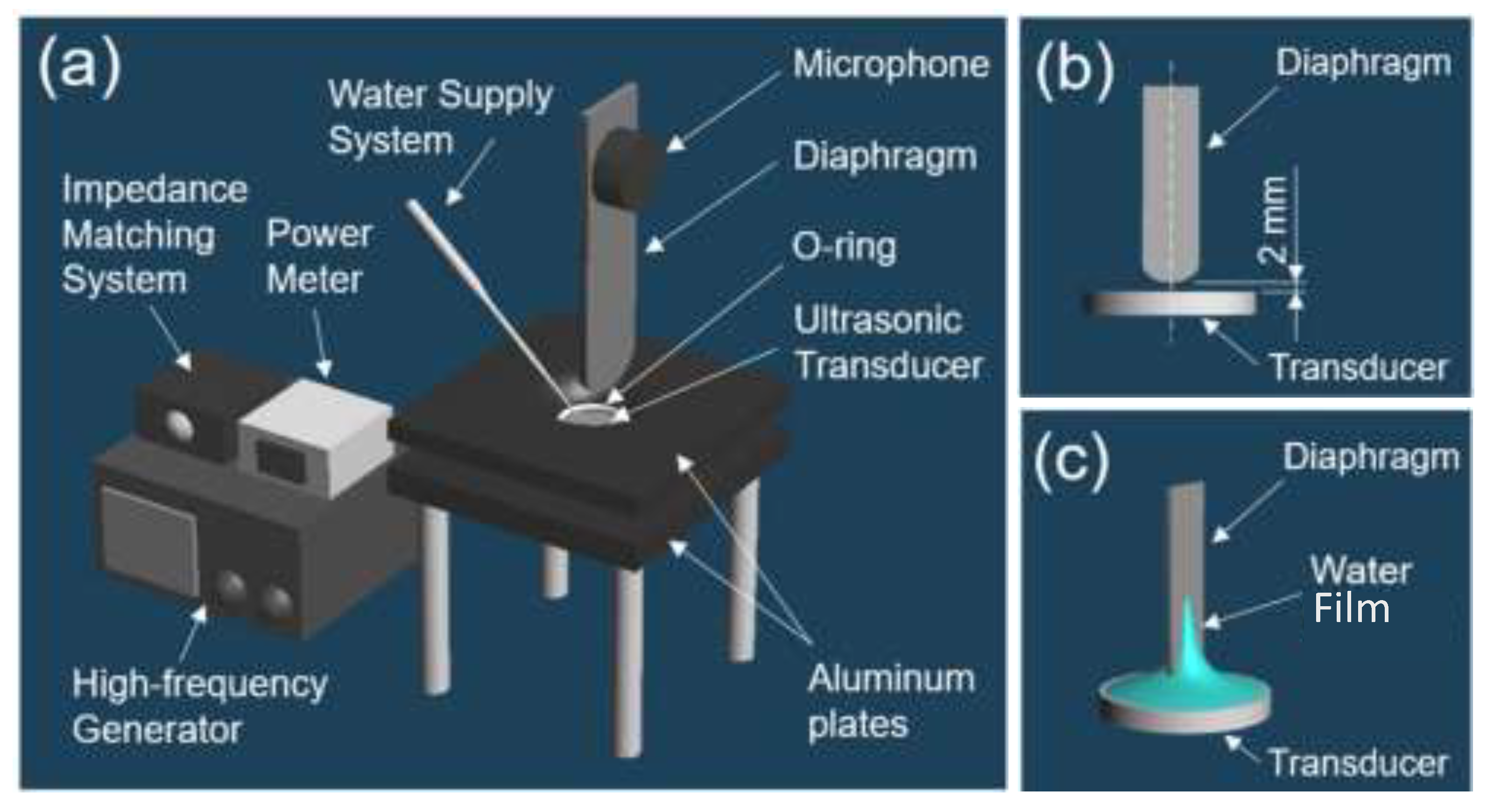
Apparatus used in the experiments is shown in
Figure 1. A diaphragm made with SUS430 stainless steel was clamped at its top edge, as shown in
Figure 1a. Two different surface treatments were conducted to make the diaphragm hydrophobic and hydrophilic. For the former diaphragm, hydrophobic material (Tofumal, Fujikura Co., Ltd., Tokyo, Japan) was coated on the surface of the diaphragm by a dip-coating method. For the latter, the diaphragm was irradiated with argon plasma after it was ultrasonically cleaned with ethanol for 3 min. The size of the diaphragm was 65 mm long, 12.5 mm wide, and 0.1 mm thick. An ultrasonic transducer was placed at the bottom of the container with a 2 mm gap and indirectly excited the diaphragm, as shown in
Figure 1b. Machined aluminum plates were used to clamp the transducer with a silicone O-ring with a 14 mm inner diameter. A high-frequency power of 2.4 MHz was applied to the transducer (HM-124, Honda Electronics, Aichi, Japan) from a high-frequency power supply through an impedance-matching system. The impedance-matching system was adjusted to achieve a standing wave ratio (SWR) of 1.5 and 95% transmission of RF power to the transducer (IM3570, Hioki, Nagano, Japan). The net power applied to the transducer was measured based on the difference between the incident and reflected waves using a power meter (Bird 4421, Bird, Solon, OH, USA). The bottom tip of the diaphragm was soaked in a water container in the aluminum plate. Distilled water was continuously supplied onto the transducer throughout the experiment so that the volume (approximately 650 mL) and depth (approximately 1 mm) of the water on the transducer remained constant. All experiments were performed at a temperature of 24 °C and 55% humidity. In the experiments, a water film was formed on the surface of the oscillating diaphragm, as shown in
Figure 1c, and atomization occurred from the water film under a limited condition, as discussed later.
The experiments conducted were roughly divided into 3 types: one with hydrophobic diaphragm, one with hydrophilic diaphragm and one with atomization ceased by contact with a glass sheet.
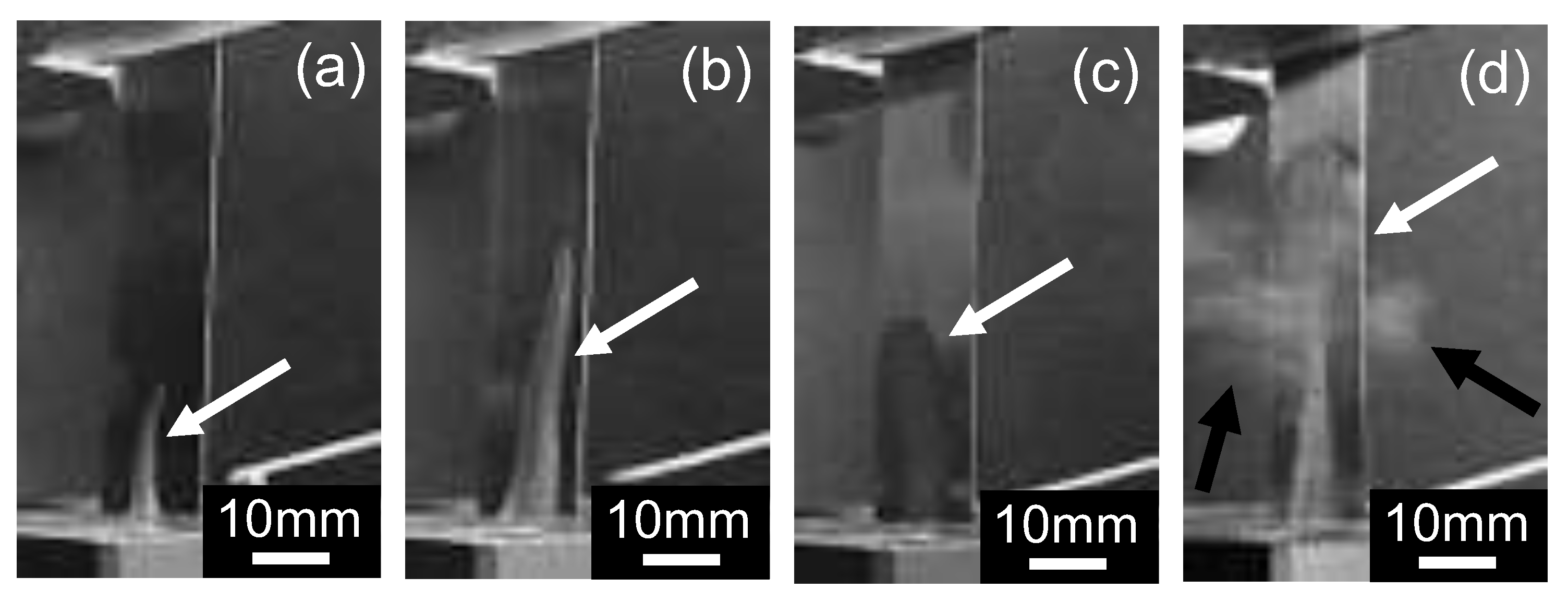
Figure 2a–d show water film formed on the surface of the diaphragm. Results of the experiments related to water film are shown in
Table 1. In the experiment with hydrophobic diaphragm, the shape of the water film was column-like, as shown in
Figure 2a,b. With an increase in the power of the transducer, height of the water pillar was increased, but its aspect ratio almost remained constant. The percentage of water coverage on the diaphragm was small, and no atomization occurred in the hydrophobic case. In the cases with a hydrophilic diaphragm, the diaphragm was widely covered by water film, with a surface coverage of as much as 73.5%. Continuous atomization was observed in the hydrophilic case, with 6.0 W of incident power, as shown in
Figure 2d.
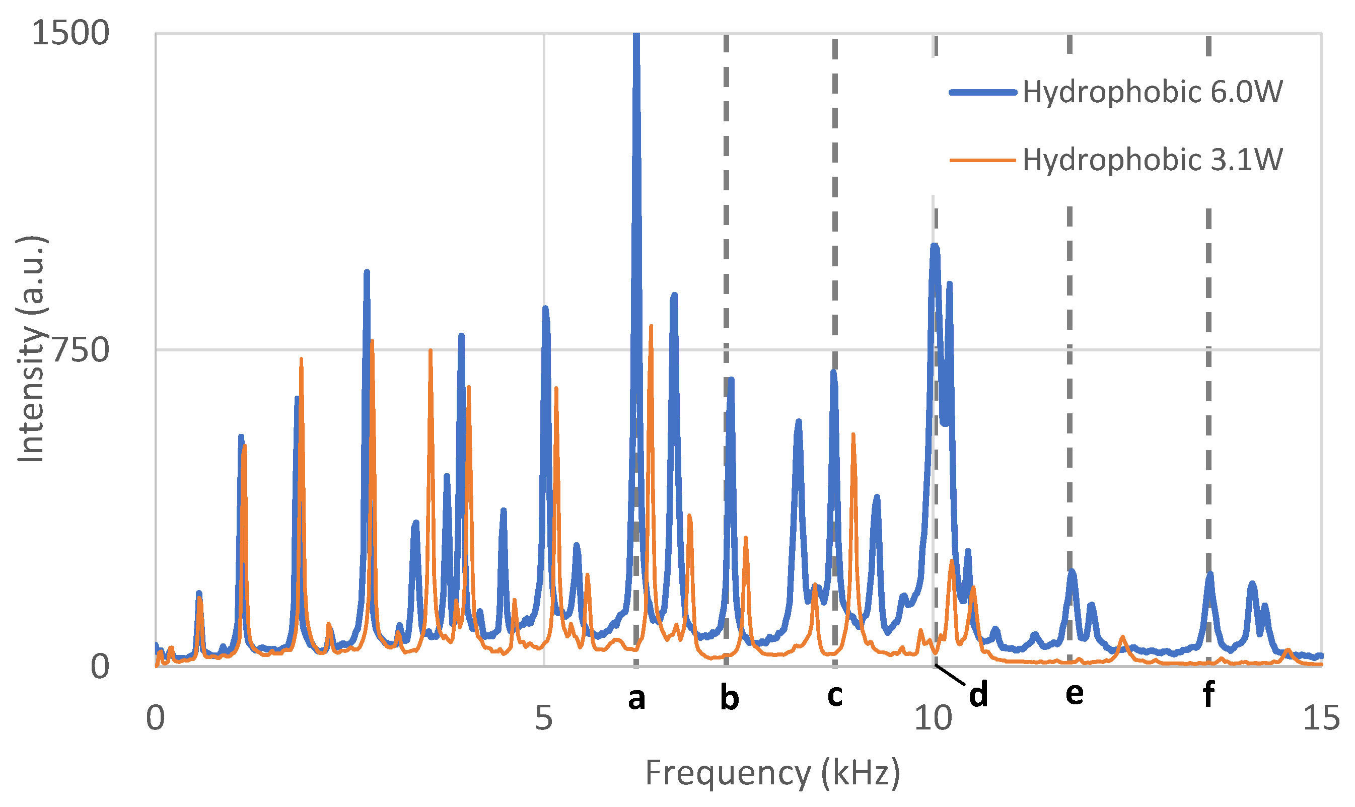
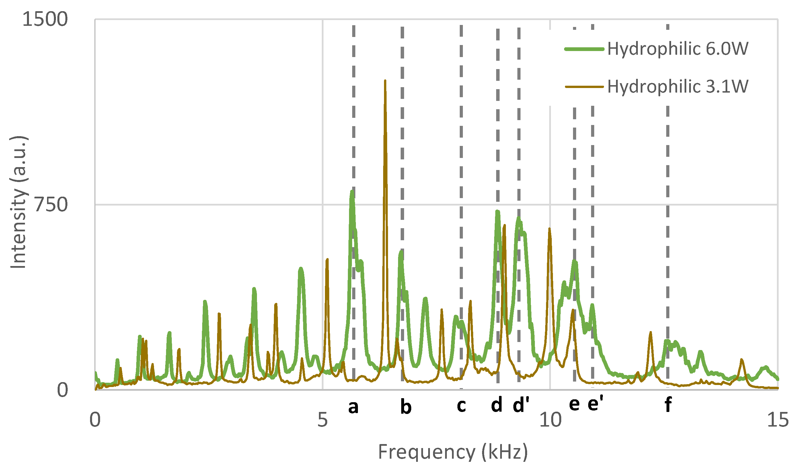
Figure 3 and
Figure 4 show acoustic signals processed by fast Fourier transform from the experiments with hydrophobic and hydrophilic diaphragms. For both types of diaphragms, it was observed that peak frequencies shifted in direction to lower frequency with an increase in the incident power of the transducer. Significant peak frequencies are marked as vertical dashed lines
a to
f.
It is important to note that attenuation of the signals in the hydrophilic case where atomization occurred was larger in the overall frequency range than that in the hydrophobic case where no atomization occurred.
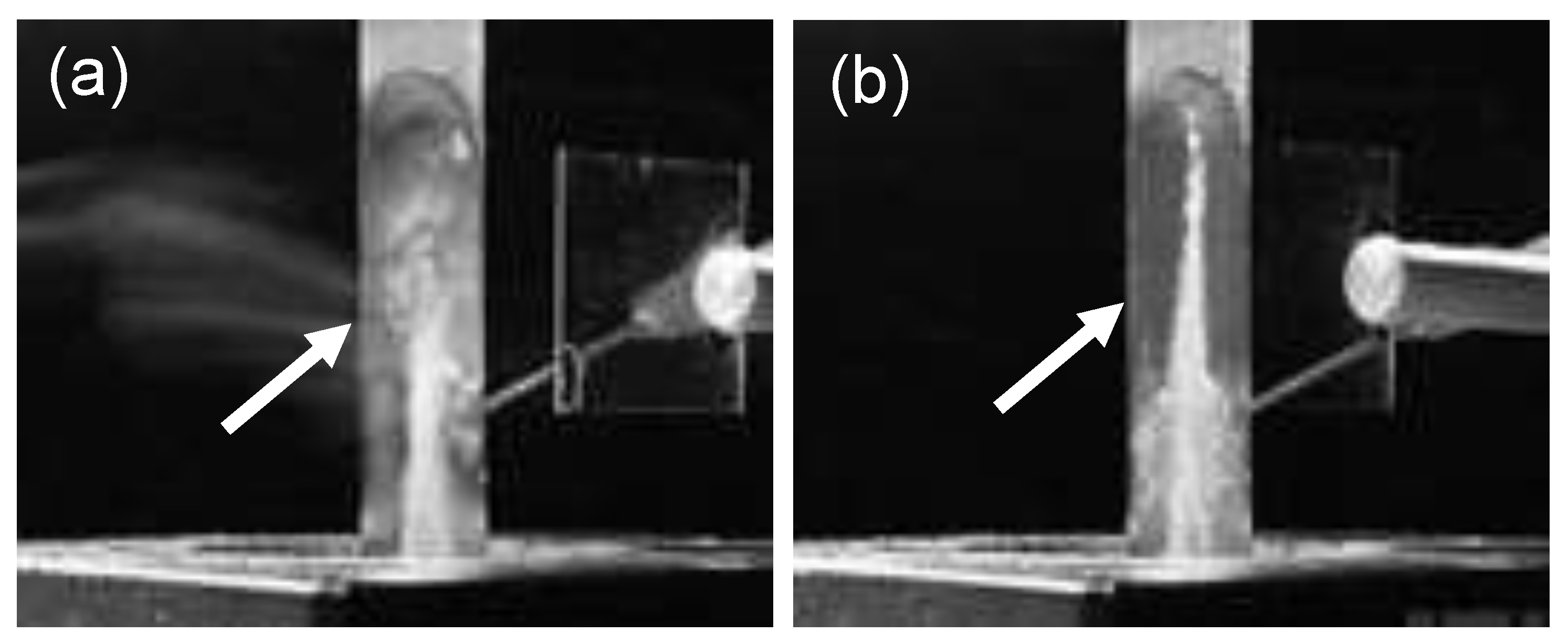
In the experiment with the hydrophilic diaphragm, atomization was forcibly ceased by putting a thin glass sheet in contact with the water film. The glass sheet was moved so that it touched only the water film and never touched the diaphragm, as shown in
Figure 5a,b. Therefore, the diaphragm kept oscillating after the contact. The surface wave appeared to be attenuated, and the atomization ceased as intended. However, coverage of the water film on the diaphragm did not significantly change, as shown in
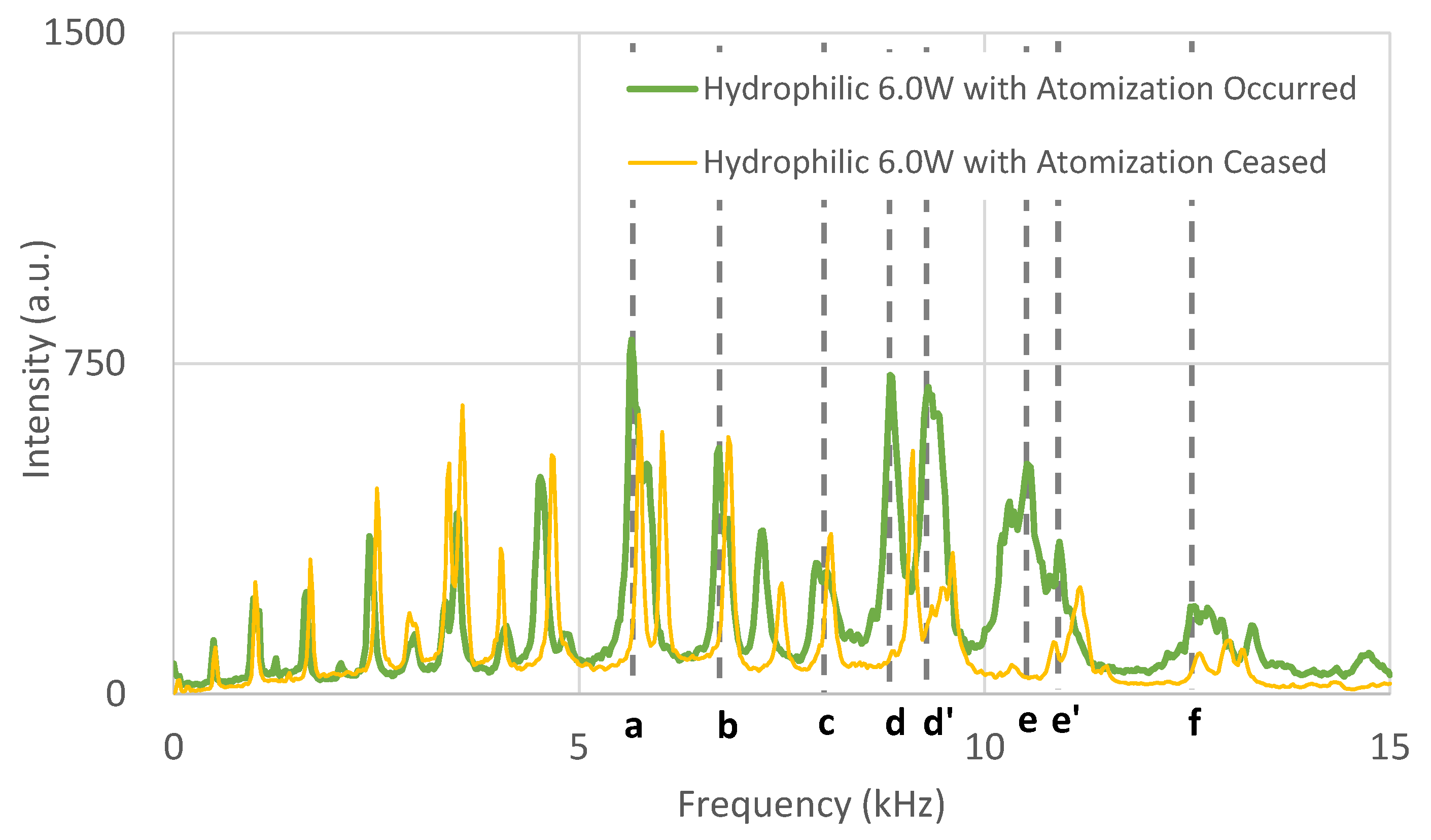
Figure 5b. The FFT signal in the last experiment is shown in
Figure 6. It was found that peak signals in the higher frequency range, such as
e and
f, significantly reduced after the cessation of atomization. This result suggested that the resonation of the diaphragm in the higher frequency region was intimately related to conditions of the atomization.
3. Numerical Analyses
3.1. Finite Element Formulation of Harmonic Response of Linear Elastic Materials
As preparation of finite element formulation for interaction between the diaphragm and water film in the next section, a summary of the general finite element formulation for dynamics of solids, which is applicable to the diaphragm, is presented in this section.
For static problems of linear elastic materials, the governing equation and boundary conditions are written as [
27]
where
is an operator matrix of spatial derivatives expressed as
σ is a row vector consisting of components of the stress tensor that is expressed as
and
b is body force per unit volume acting on the elastic body.
Γ is the surface of the body where traction is known as
, and
n is the direction cosine of the surface.
Integrating over the whole domain Ω, with multiplication by arbitrary trial function
W, a weak form of the governing equation is obtained as follows.
The finite element discretization of the equation above is conducted as
Following relationships for trial function, displacements, and strains are used in the equation above.
where
N is the interpolation function in an element, and
and
are nodal trial vectors and nodal displacement vectors, respectively. By letting
ε as a row vector consist of components of strain in the same manner as the stress, the relationship between stress and strain for linear elastic materials is defined as
For dynamic problems, governing Equation (1) can be rewritten in the following form by introducing Corioli’s force and viscous damping force into
b [
28]:
where
μ and
ρ are the viscous damping coefficient and the mass density of the material, respectively.
By a similar means of finite element discretization conducted for Equations (6)–(10), the following equation is obtained.
Rewriting this to the following form, we have a system of equations to be solved in the finite element analyses.
where
The right-hand term can be written as
For an analysis of steady-state vibration under sinusoidal cyclic excitation, both the displacement and excitation force are written as harmonic functions, expressed as [
29]
By substituting the above relationships into Equation (13), the following equation is obtained.
This system of equations with complex numbers is solved in a finite element analysis of the harmonic response of the oscillatory body in the present study.
In practical analyses of dynamic problems, Rayleigh damping expressed in the following form is often adopted as the damping matrix
C [
28].
The coefficients
α and
β can be determined by solving a system of equations with the following relationships for two damping ratios
and resonance frequencies
.
The numerical damping coefficient γ is used to eliminate unintended scatter of results in the high-frequency domain.
3.2. Modeling of Interaction Between Diaphragm and Water Film
While the oscillating body that consists of the diaphragm and water film in the experiment was under steady-state vibration, the water film was just attached to the surface of the oscillating diaphragm without macroscopic change in its shape and thickness. Therefore, the displacement of material points in the water film is assumed to be small. Based on this assumption, an approximation of the Navier–Stokes equation is conducted to model the interaction between the diaphragm and water film as follows.
In fluid dynamics, the principle of energy conservation is written as a Navier–Stokes equation. For an incompressible Newtonian fluid, the equation is expressed with
v representing the fluid’s velocity,
ρ as its mass density, and
μ as its viscosity [
30]:
where
p and
fg are pressure and external acceleration, such as gravity, respectively.
In this equation, the time rate of change in fluid velocity
v is expressed as a material derivative. When the displacement of the material points is small, to the extent that the Eulerian derivative approximately equals the Lagrange derivative, as expressed as
, the Equation (25) can be rewritten as follows:
where
u is a displacement vector of the material points.
This equation can be translated to the following weak form in the same way that Equation (5) is derived.
After the finite element discretization for the equation above, a system of equations is obtained as follows.
Then, the following equation in a similar form is obtained, as already derived for the case of solid dynamics in Equation (13).
where
It is important to note that this system of equations can be solved by a finite element solver for solid mechanics, with simple efforts on a user subroutine for the viscosity matrix Cf. Therefore, responses of the diaphragm and water film, which were composed of an oscillating body, were simultaneously solved with this formulation in the present study.
3.3. Finite Element Models
One of the finite element models in the present study is shown in
Figure 7. The analyses were conducted by finite element solver Marc 2023.1 (MSC Software, Newport Beach, CA, USA). First, the eigenvalue problem of the diaphragm was solved, and then the harmonic response analyses of the whole oscillating body, with consideration of interaction between the diaphragm and water film.
The diaphragm and water film were both modeled from thick shell elements using the Mindlin theory, in which out-of-plane components of shear stress are calculated [
31]. A flat lattice-shaped mesh was created from quadrative shell elements. The number of elements and nodes were 3423 and 3200, respectively. Since the present model calculates steady-state vibration under harmonic excitation, the thickness of the water film and the position of material points in the water film were assumed not to change. Therefore, the constant thickness of the water film was assigned to the shell elements. The thicknesses of the water film for the cases of hydrophobic and hydrophilic diaphragms were set as 0.5 mm and 0.3 mm, respectively, based on approximate measurements of experimental results. Nodes on the water film were rigidly connected to corresponding nodes on the surface of the diaphragm by MPCs, as shown in magnified form in
Figure 7.
A boundary condition of fixed displacements was defined at the top of the diaphragm. A harmonic load was applied at the bottom of the diaphragm. In the experiment, the diaphragm was indirectly excited by the ultrasonic transducer, and the source of the excitation to the diaphragm was considered as a sub-harmonic wave of the primary wave with a frequency of 2.4 MHz from the transducer. To incorporate this condition into the model, the magnitude of the harmonic load was set as a dependent variable of frequency, with a relationship in which the magnitude was proportional to the square of the frequency.
Table 2 shows the material properties used in the analyses. Coefficients of Rayleigh damping for the diaphragm were chosen as
α = −2.0 × 10
2 and
β = 1.0 × 10
−7, based on attenuation of the experimental results. Numerical damping
γ = 5.0 × 10
−3 was used. As already mentioned in
Section 3.2, the viscous damping effect due to the interaction between the diaphragm and water film was incorporated through the user subroutine UCOMPL. The water film adhered to the surface of the diaphragm in the case of the hydrophilic diaphragm according to a formula of Newtonian fluids, while it freely slid on the surfaces in the hydrophobic sample. Therefore, the viscosity effect was only considered in analyses with the hydrophilic diaphragm.
4. Results and Discussions
Resonance frequencies obtained from the eigenvalue analysis are shown, with results from the experiments, in
Table 3. Frequencies in the numerical analysis that are closest to the peak frequencies in the hydrophobic cases experiment with 3.1 W of transducer power were chosen in the table. This result shows that the body consisting of the hydrophobic diaphragm and water film in the experiment oscillated at resonance frequencies of the diaphragm. Modal shapes which correspond to each resonance frequency are shown in
Figure 8. The modal shapes were basically bending modes without twist, and the number of nodes and anti-nodes increased with an increase in the frequency. It is noted that many modes with twists exists between the modes in the figure although they are not shown. This tendency indicates that the whole surface of the diaphragm has a large amount of acceleration in the out-of-plane direction, especially in higher-frequency domains, and can be a potential region where atomization occurs.
Figure 9 shows the harmonic response from the numerical analysis using the hydrophobic diaphragm. Since the condenser microphone used in the experiments mainly senses acoustic pressure, the amplitude of the diaphragm in the analyses is plotted. The percentage of power transferred to the diaphragm from the transducer was unknown in the experiments. Therefore, the result that is important in this plot is not the absolute value of the amplitude but the relative variation with respect to frequency. Thus, the amplitude was normalized by a single average value of all results in the analyses.
The red and blue curves in
Figure 9 show results with 3.1 W and 6.0 W of transducer power, respectively. By increasing the power in the experiment, the height and width of the water pillar increased, and the peak frequency shifted in the direction of the lower frequency. This tendency was reproduced in the results of the analysis. Peak frequencies in the results of the experiments are marked as vertical dashed lines
a to
f. The peak frequencies of the experiments and analyses agreed well. As the main difference between models with 3.1 w and 6.0 W is the distribution of water thickness, this result indicates that the peak shift mainly occurred through an increase in the mass of the oscillating body that consists of the diaphragm and water column.
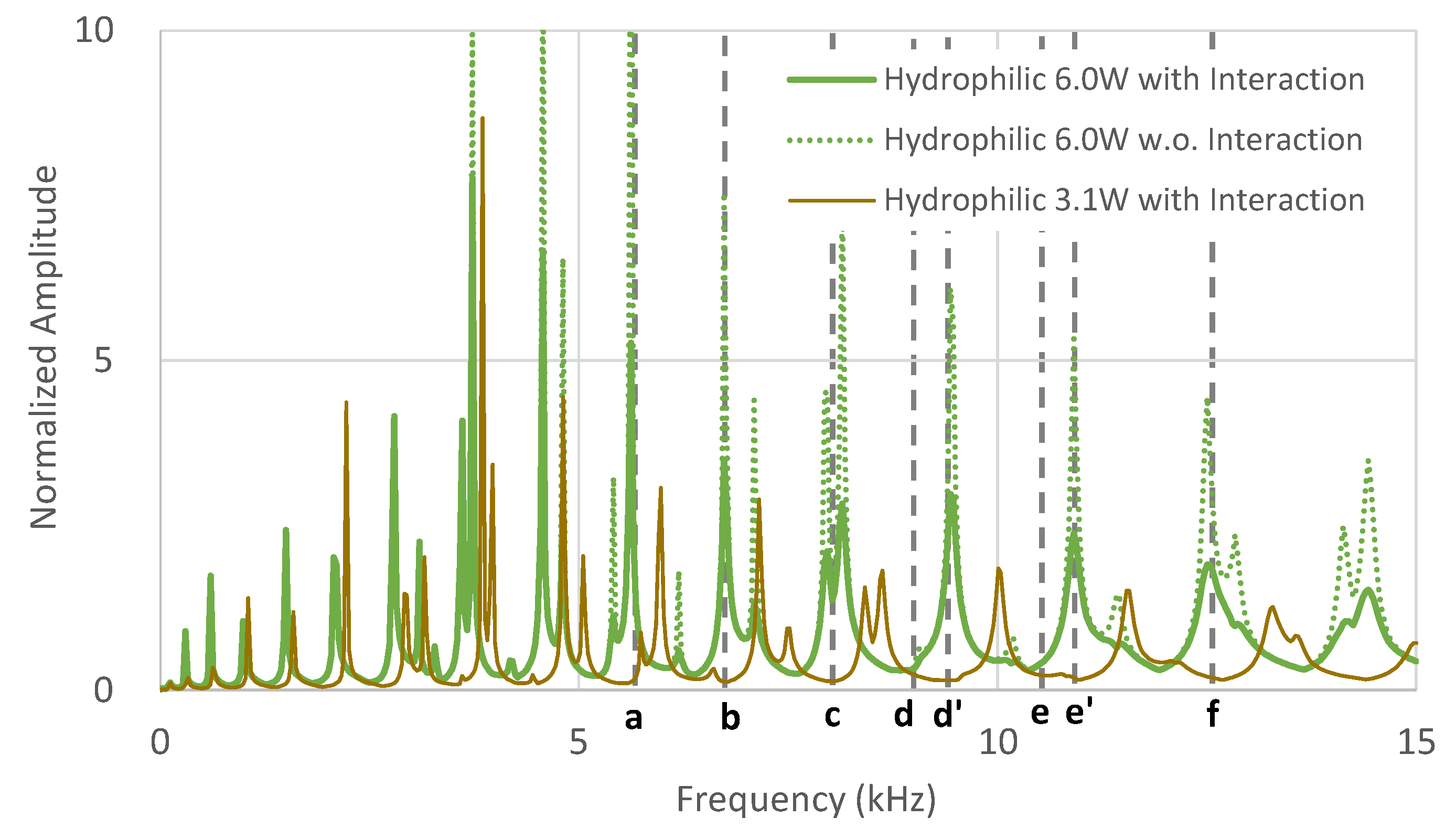
Results from the numerical analyses using a hydrophilic diaphragm are shown in
Figure 10. The green and brown curves correspond to results when the power of the transducer was 3.1 W and 6.0 W, respectively. Results with and without consideration of the interaction between the diaphragm and water film were compared by solid and dashed lines. Vertical dashed lines show the frequencies marked in the results of the experiments.
The peak shift in the results of the experiment was reproduced in the numerical analyses, as well as in the case of the hydrophobic diaphragm. For markers a to f, the deformed shape of the diaphragm in this harmonic analysis was almost the same as that obtained in the eigenvalue analysis despite the shift in the frequencies. In the experiments with the hydrophilic diaphragm, atomization occurred, and the intensity of the signal-at-peak frequencies became smaller than that in the hydrophobic case. This tendency was qualitatively expressed by incorporating the interaction between the diaphragm and water film with viscosity effects. It was indicated through these results that one of the reasons for the reduction in the intensity of the signal in the experiment is that extra energy was dissipated in the water film due to the process of atomization. The quantitative relationship between atomization and energy dissipation by the interaction is to be investigated in further study.
The conditions of atomization for the present experiments are discussed as follows. Based on the experiment in which the atomization was ceased, frequencies higher than 10.0 kHz, which are marked as
e and
f in
Figure 4 and
Figure 10, appeared to have a close relationship to the conditions of atomization. Therefore, the diameters of the droplets formed by 10.0 kHz and 2.4 MHz of excitation frequencies were estimated by Lang’s equation, which is expressed as a function of excitation frequency
f as [
8]
The diameters were 86.5 μm for f = 10.0 kHz and 2.32 μm for f = 2.4 MHz, respectively. The average size in the present experiment was 2.75 μm and was close to the size for f = 2.4 MHz. This result indicates that atomization mainly occurred by a surface wave from the transducer. However, judging from the results of the hydrophobic cases in which no atomization occurred, the power transferred to the surface of the water film was not sufficient to initiate atomization by itself. It is hypothesized that the extra energy source that initiates atomization in hydrophilic cases is the interaction between the diaphragm and water film.
As already mentioned in
Section 1, Goodridge et al. found that the acceleration threshold for atomization depends on the excitation frequency and surface tension for low-viscosity fluid and viscosity for viscous fluids [
10]. For low-viscosity fluids, the acceleration threshold is expressed as
These acceleration thresholds
αth were compared to maximum acceleration
αmax caused by the sub-harmonic waves in the present experiments with the following ratio.
By letting
A0 be the amplitude of the oscillation, acceleration is expressed as
Therefore, the maximum amplitude is
In a case with frequency
f = 10.0 kHz, which is marked as e in
Figure 4 and
Figure 10,
where 10.0 μm was used as amplitude
A0 because the amplitude was estimated in the order of 10
1 μm from the results of the present experiments. For the frequency
f = 6.2 kHz, which is marked as
a in
Figure 4 and
Figure 10,
Although more precise measurements of the amplitude of the diaphragm should be conducted in a further study, these results indicate that oscillation by sub-harmonic wave with 10.0 kHz of frequency provides enough acceleration for the initiation of atomization, but the acceleration with 6.2 kHz of frequency is insufficient. This is one of the reasons why the intensity of the signal became lower, mainly in a frequency range higher than 10 kHz, in the experiment where the atomization ceased, as shown in
Figure 4. In summary, the results of the experiments and numerical analyses in the present study showed the possibility that atomization occurred when the superposed accelerations of the primary wave from the ultrasonic transducer and the extra acceleration due to interaction between the oscillating diaphragm and water film exceeded the acceleration threshold for atomization.
5. Conclusions
Numerical analyses of an oscillating body in previously conducted experiments of atomization were conducted for a better understanding of the mechanisms of atomization. In the experiment, an ultrasonic transducer indirectly excited a beam diaphragm through water. A water film formed on the surface of the diaphragm and oscillated together with the diaphragm, and atomization only occurred in the experiment with the hydrophilic diaphragm. Numerical models using the finite element method, considering the interaction between the diaphragm and water film, were developed. From the comparison of the results of the experiments and numerical analyses, the following conclusions were obtained.
The onset of atomization was indicated as a result of the superposed acceleration of the primary wave from the ultrasonic transducer and extra acceleration due to the interaction between the resonating diaphragm and the water film.
Only the higher range of the resonance frequencies of the diaphragm (more than 10.0 kHz in the present case) contributed to the atomization onset.
Atomization required the hydrophilic surface of the diaphragm to provide sufficient acceleration to the surface of the water film. The hydrophobic diaphragm was not suitable for atomization.
In future studies, the amplitude of the diaphragm will be experimentally measured for a more precise evaluation of the superposed acceleration of the surface wave and oscillating diaphragm. Methodology to quantitatively estimate energy dissipation due to interaction between the diaphragm and water film is being actively sought.
