Abstract
This study investigates the dynamic behavior of a three-body tethered satellite system with a flexible tether, focusing on a scenario in which a payload is transported along the tether connecting two satellites. Traditional models use rigid tethers, limiting the analysis of complex dynamics such as tether deformation, slack, and rebound. To address these limitations, we employed the absolute nodal coordinate formulation (ANCF) to model the flexibility of the tether. We derived nonlinear equations of motion using Lagrange’s equation and solved them using the Newmark time integration method to obtain the dynamic responses of the satellite system. Our findings revealed that the Coriolis effect caused significant deviations in the payload trajectory as its mass and speed increased, leading to greater tether deformation and slack, and potential system destabilization. Additionally, axial force fluctuations in the tether varied notably as the payload moved, transitioning between tensile and compressive states. This study provides a more accurate representation of three-body tethered satellite systems by incorporating tether flexibility, offering valuable insights into the dynamic behavior and stability of the system.
1. Introduction
Satellite systems have undergone significant advancements over the past few decades, driven by the increasing demand for robust and efficient space exploration and communication technologies. Among various configurations, tethered satellite systems have garnered substantial attention due to their potential applications in space debris removal, intersatellite communication, and satellite service missions. The tethers used in these systems can be classified into four types: momentum exchange tethers, gravity gradient stabilization tethers, space elevator tethers, and electrodynamic tethers. A typical tethered satellite system comprises two or more satellites connected by a flexible tether, allowing for unique dynamics and control opportunities absent in free-flying satellite formations.
A comprehensive review [1] has recently been published, detailing the dynamics of tethered systems in various space applications. It encompasses theoretical foundations, modeling techniques, control strategies, and practical implementations, highlighting advancements and challenges in the field. Research on tethered satellite systems can be classified according to the number of satellites connected by tethers. Systems with two satellites connected by a tether are referred to as two-body-tethered satellites [2,3,4,5,6,7,8,9,10,11,12,13,14,15,16], those with three connected satellites are termed three-body tethered satellites [17,18,19,20,21], and those with multiple connected satellites are known as multibody tethered satellites [22]. Furthermore, the research can be divided between studies on dumbbell models, which do not consider the transverse deformation of the tether [2,3,4,5,6,7,8,9,10,11,12,13,17,18,19,20,21,22], and studies on flexible tether models, which account for this deformation [14,15,16].
Numerous studies have explored the dynamics of tethered satellite systems using a two-body dumbbell model, where the tether linking two satellites is assumed to be massless and undeformed. Anderson and Hagedorn [2] investigated the controllability of a tethered geosynchronous satellite solely through tether length adjustments in a central inverse squared gravity field. Nakanishi et al. [3] determined the in-plane periodic solutions of a dumbbell-shaped satellite system in elliptical orbits via bifurcation with respect to orbital eccentricity. Zhao et al. [4] derived analytical first-order solutions for the librational angles of a tethered satellite subjected to small, continuous, and constant thrust in the transverse, tangential, radial, and binormal directions. Sun et al. [5] developed dynamic equations for a tethered system during orbital maneuvers and analyzed the equilibrium position stability for in-plane angles during omnidirectional maneuvering in the orbital plane. Kojima and Taroka [6] addressed the deployment control of a tethered satellite system to rendezvous a sub-satellite with a target object orbiting at a lower altitude. Liu et al. [7] formulated dynamic equations for a tethered satellite system during orbital maneuvers and designed a controller using the small-gain theorem based on a control-oriented model. Yu et al. [8] investigated the chaotic behavior of an in-plane tethered satellite system influenced by atmospheric drag and the Earth’s oblateness.
Some studies treat two-body tethered satellites as dumbbell models, where the tether has no mass but is longitudinally elastic. Combot et al. [9] studied the integrability of an elastic satellite model whose center of mass moved in a circular Keplerian orbit around the center of gravity. They modeled the satellite as two-point masses connected by an extensible massless spring that obeyed Hooke’s law. Liang et al. [10] analyzed the dependence of deployment friction on the tether diameter, deployment velocity, and deployment angle. They also evaluated the effects of these deployment parameters on the dynamics of tethered satellites using both extended and unextended dumbbell models. In a study by Zhao et al. [11], the dynamic equations of a tethered system during orbital maneuvering were established based on a dumbbell model of a tethered satellite. Furthermore, considering the elastic strain of the tether in the dynamic model, the effects of the degree of slackness, the initial states of the librational angles, and variations in thrust acceleration on the tethered satellite were analyzed as the tether became slack.
Among the studies analyzing the dynamic behavior of two-body tethered satellites, some modeled the tether as lumped masses to consider its mass and lateral deformation. Zhong and Zhong [12] investigated the relative dynamics and control of tethered satellites during the deployment process using a dumbbell model with tether mass and a lumped-mass model of a tethered satellite system. Sun et al. [13] adopted a dumbbell model to analyze the dynamics of a tethered system, fully considering the mass variations in the base satellite. In addition, a lumped-mass model was introduced to reveal the strong coupling between the librational and vibrational characteristics.
Recent studies have focused on the dynamic analysis of two-body tethered satellites, considering the lateral deformation of the tether through the absolute nodal coordinate formulation (ANCF) [23]. Shan and Shi [14] examined and compared modified dumbbell, lumped-mass, and ANCF models to describe a tethered post-capture system for space debris removal. Zhang et al. [15] used the ANCF to investigate the deployment of a tether in a tethered satellite system, highlighting complex dynamic properties such as the large deformation, slack, and rebound. Bai et al. [16] employed variable-length elements based on ANCF to predict the length variations and flexibility of a tether during the retrieval and station-keeping phases.
Various studies have examined the dynamics of three-body tethered satellite systems in which three satellites are interconnected by tethers. These analyses primarily focused on the dynamic behavior of the system during tether deployment or retrieval, as well as during the transportation of a payload along the tethers. For example, Jung et al. [17] employed a two-piece dumbbell model in the dynamic analysis of a tethered satellite system with a moving mass. Similarly, Kuo [18] utilized a two-piece dumbbell model to explore the nonlinear dynamics and control of such systems. Shi et al. [19] investigated the dynamic characteristics of a three-body tethered satellite system in large elliptical orbits and developed a control strategy to mitigate liberation during orbital transfer. Shi et al. [20] used a two-piece dumbbell model to investigate the dynamics and vibration suppression of a tethered system with a moving climber in a circular orbit. Jung et al. [21] analyzed the nonlinear dynamic behavior of a three-body tethered satellite system during deployment and retrieval by considering the variable orbital radius of the instantaneous mass center of the system. Shi et al. [22] employed a multiple dumbbell model to investigate the dynamics and liberation suppression of multibody-tethered satellites in elliptical orbits, where the system experiences periodic excitation owing to changes in the gravity gradient.
The recent literature has shown significant interest in the control of tethered satellite systems, with a variety of approaches being developed to tackle the complexities of their dynamics. Li et al. [24] examine control mechanisms for tethered satellite systems using elastic tethers, highlighting the importance of accurate modeling to capture the elastic behavior of the tether, which directly impacts the overall dynamics of the system. Santos et al. [25] take a complementary approach by investigating optimal control strategies tailored for tethered satellite systems, emphasizing the interaction between propulsion and tether deployment. Their research indicates that effective control necessitates a careful balance between propulsion forces and tether dynamics to optimize system performance. Wang et al. [26] contribute further to this area by focusing on adaptive control in tethered satellite systems, particularly under conditions of uncertainty and external disturbances. Their findings stress the need for robust control mechanisms that can respond dynamically to real-time changes, ensuring both system stability and performance. Together, these studies highlight the role of advanced control strategies in tethered satellite systems. They advocate for models that not only incorporate the elastic characteristics of tethers but also emphasize the necessity of adaptive responses to uncertainties, paving the way for enhanced control frameworks in future research.
To the best of our knowledge, no prior research has investigated the dynamic behavior of a three-body tethered satellite system while considering the flexibility of the tethers. Previous studies predominantly modeled three-body tethered satellite systems as a two-piece dumbbell, treating the tethers as rigid rods. Although dynamic behaviors such as deformation, slack, and rebound have been explored in the context of two-body satellite systems with flexible tethers, similar considerations have not been extended to the three-body configurations. In systems where a payload is transferred between two satellites, the deformation of the tethers caused by the moving payload cannot be accurately analyzed using a rigid two-piece dumbbell model. Therefore, studying the dynamic behavior of three-body tethered satellite systems requires modeling the tethers as flexible bodies.
In this study, we analyzed the dynamic behavior of a three-body tethered satellite system comprising a payload transported along a flexible tether connecting two satellites. The remainder of this paper is organized as follows. Section 2 models the two satellites and payload as point masses, with the tether modeled using the ANCF to account for its flexibility. Section 3 derives and expresses the discretized nonlinear equations as matrix-vector equations using Lagrange’s equation. The Newmark time integration method [27] is applied to these equations to calculate the dynamic response. Section 4 analyzes the dynamic behavior of the tethered satellite system as the payload moves along the flexible tether connecting the two satellites. Finally, Section 5 summarizes the findings and presents the conclusions.
2. Modeling of a Tethered Satellite System
Consider tethered satellites with moving payloads, as shown in Figure 1. For simplicity, we modeled the two satellites and the moving payload as point masses without moments of inertia. Since the tether length in typical tethered satellite systems is very large compared to the dimensions of the satellites or payloads, they can be assumed to be point masses. However, if the tether length is relatively short, the positions of the centers of mass and the mass moments of inertia for the satellites and payloads must be taken into account. In Figure 1, and represent the masses of the two satellites and denotes the mass of the payload. The satellites and payload were assumed to be in the same orbital plane. The tether connecting the two satellites, with the total length L, was modeled as a flexible string with mass. The payload moved along the tether with a constant speed . Since the tether’s length is much greater than its cross-sectional dimensions, its bending rigidity can be ignored, allowing us to model the tether as a string.
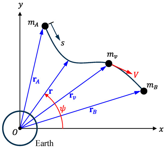
Figure 1.
Dynamic model of tethered satellites with a moving payload, assuming the satellite to be a point mass. is the position vector of the tether, , and are the position vectors of satellites A and B, and is the position vector of the payload.
Position vectors with their origin at the center of the Earth were employed to track the movements of the satellites and payload. In Figure 1, the positions of satellites A and B, along with the payload, are denoted by position vectors , , and , respectively, using the absolute coordinate system with the origin . The position of a particle on the tether is expressed as , which can alternatively be described by its orbital radius (the magnitude of ) and the true anomaly . Since the position of the tether depends on both time and arc length , its coordinates and are functions of and . Therefore, the position vector of the tether can be represented as
Since the coordinate of satellite is and that of satellite is , the position vectors of satellites A and B, and , can be expressed as
In contrast, the payload moves along the tether, so the arc length , which represents the position of , is a function of time . Therefore, the position vector of the moving payload can be expressed as
Before deriving the equations of motion, we need to represent the kinetic and potential energies of the tethered satellite system in terms of the above position vectors. The kinetic energy of the system is given by
where the dot represents differentiation with respect to time, is the mass density of the tether, and is the cross-sectional area of the tether. Assuming a uniform tether, and are constant along the length. The first term represents the kinetic energy of the tether, whereas the last three terms represent the kinetic energies of the satellites and payload.
Similarly, the potential energy of the tethered satellite system can be written as
where is the universal gravitational constant, is the Earth’s mass, is the Young’s modulus of the tether, and is the strain of the tether. The values of and are given by and kg, respectively. Using the one-dimensional Lagrange strain, the strain can be represented as
In this study, the damping effect of the tether is neglected for simplicity.
The tethered satellite system with a moving payload was discretized using the ANCF. The tether was discretized into uniform two-node elements, as shown in Figure 2a, where the numbers represent the global node numbers. The -th element consists of nodes and . Satellites A and B are positioned at nodes and , respectively, whereas the payload moves along the -th element. Figure 2a shows that the moving payload is located between nodes and . In Figure 2b, is the arc length from satellite to node , and are the global nodal coordinates of node , and and are the derivatives of and with respect to at , respectively.
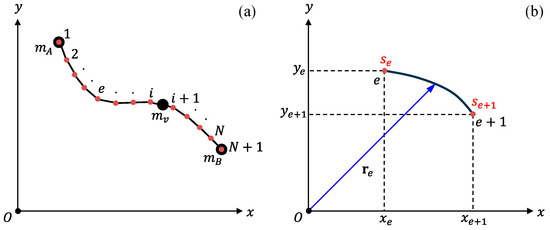
Figure 2.
Discretization of tethered satellites with a moving payload: (a) ANCF model and (b) two-node element. The numbers represent the nodal points of the discretized model.
The position vector of a point inside element , denoted by , can be represented as
where is a shape function matrix, and is an element nodal coordinate vector given by
Using the coordinate transformation given by
where is the parametric coordinate and is the constant element length defined by , the position vector of a point inside element can be rewritten as
where
with
Next, we consider the position and velocity vectors of the moving payload as it travels along the tether at a constant speed . In this scenario, both the nodal coordinate vector and shape function matrix become functions of time. When the moving payload is located between nodes and , its position vector can be represented as
From Equation (9), the time derivative of the parametric coordinate is given by . Differentiating the position vector with respect to time yields the velocity vector of the moving payload:
where the prime (′) represents differentiation with respect to the parametric coordinate .
3. Discretized Equations of Motion
After discretizing the kinetic and potential energies using the ANCF, they were substituted into Lagrange’s equation to derive the corresponding discretized equations of motion. First, we addressed the discretization of the kinetic energy using the ANCF. In the discretized model, the position vectors of satellites A and B correspond to and , respectively. For a model discretized into N elements, as shown in Figure 2, the kinetic energy, originally expressed by Equation (4), can be represented by the following equation:
By substituting Equations (10) and (14) into Equation (15), the kinetic energy of the tethered satellite system can be expressed as
Similarly, the potential energy of a satellite system can be described using a discretized model. The potential energy, as given by Equation (5), can be rewritten as
Since the magnitude of the position vector (representing the distance from the center of the Earth) is the square root of the product of the vector’s transpose and itself, we express the magnitude of as
Furthermore, the Lagrange strain, as defined by Equation (6) can be represented by
Using Equations (18) and (19), the potential energy from Equation (17), can be written as
The discretized equations of motion can be derived by substituting the kinetic and potential energies from Equations (16) and (20), respectively, into the following Lagrange equation:
where represents the work of non-conservative forces. In this study, external forces such as solar radiation pressure and atmospheric drag are neglected, resulting in zero work resulting from non-conservative forces. For more detailed information on ANCF, refer to Shabana [28]. The derived equations of motion can be expressed as
where is the element mass matrix, is the element gyroscopic matrix due to the moving payload, is the element stiffness matrix due to the centrifugal force of the moving payload, and is the nonlinear element force vector due to the tether deformation and gravitational gradient. These matrices and vectors are given by
where , , and are square matrices, and is an column vector. By assembling all the element matrices and vectors, the following global matrix-vector equation can be obtained:
where is the global mass matrix, is the global gyroscopic matrix, is the global stiffness matrix, is the global nonlinear force vector, and is the global nodal coordinate vector, given by
The force vector is a nonlinear function of the coordinate vector . The size of the matrices was , and the size of the vectors was .
To obtain the dynamic responses of the tethered satellite system with a moving payload, the Newmark time integration method [27] was applied to the nonlinear matrix-vector equation in (27). The Newmark method is a second-order accurate, implicit time integration method that permits larger time step sizes compared to explicit methods like the Runge–Kutta method. It is particularly well-suited for long-duration problems, such as the satellite behavior analysis in this study. The Newmark method can experience convergence issues in time-response calculations dominated by the high-frequency modes of flexible bodies, such as in impact analysis. However, it remains robust against numerical instability when applied to satellite response calculations, where high-frequency modes are not predominant. Before applying the Newmark method, the displacement, velocity, and acceleration vectors at time , denoted as , , and , are approximated as , , and , respectively. Denoting , where is the time step size, the global matrix-vector equation at time can be approximated as
which is known as the balance equation. In the Newmark time integration method, the displacement and velocity vectors at time , denoted as and , are given by
where and are the algorithmic parameters given by and , respectively.
Using the displacement, velocity, and acceleration vectors at time , these vectors were updated at time . First, with the initial conditions and , the initial acceleration was computed as follows:
To compute the displacement and velocity vectors, and , using Equations (30) and (31), the acceleration vector , is required. This acceleration vector can be obtained from a nonlinear algebraic vector equation, where serves as the unknown variable, which is derived by substituting Equations (30) and (31) into Equation (29). The unknown vector can be determined by applying the Newton–Raphson iteration method to this equation. The iterative process for each time step is represented by the following equation:
where denotes the iteration number for each time step. The vector in the above equation is computed from the following equation:
where is the Jacobian matrix, given by
4. Dynamic Response Analysis
Before examining the dynamic responses of the satellite system, the responses using the proposed ANCF in this paper were verified through comparison with those obtained using the two-piece dumbbell model from a previous study [17]. When the payload speed is very low, the deflection of the tether remains relatively small. In this case, the response of the ANCF model in this study is nearly identical to that of the two-piece dumbbell model, which does not consider tether deformation. For this purpose, the payload speed was selected as 1 m/s. The material properties and dimensions used for verification were as follows: the masses of satellites A and B were 1000 kg, and the mass of the moving payload was 100 kg. The length, mass density, cross-sectional area, and Young’s modulus of the tether were 10 km, 1440 kg/m3, 2 mm2, and 131 GPa, respectively. The initial conditions for verification were 6600 km, 6610 km, , and rad/s. All material properties and dimensions were identical to those in Ref. [17], except for the density, cross-sectional area, and Young’s modulus of the tether, which were not specified in Ref. [17].
For validation, we compared the attitudes of the tethered satellite system calculated using the ANCF and two-piece dumbbell models. Figure 3a shows the attitudes derived from the ANCF model, whereas Figure 3b presents those derived from the two-piece dumbbell model [17]. In Figure 3, satellite A is depicted as a green circle, satellite B as a red square, the moving payload as a blue triangle, and the tether as a black line. The orbital direction of the satellite system was counterclockwise. For clarity when observing attitude changes, the orbital radius of satellite A is shown at its actual distance, and the length of the tether is magnified by a factor of 1000. The attitudes obtained using the ANCF model exhibited minimal deviation from those obtained using the two-piece dumbbell model in the previous study [17].
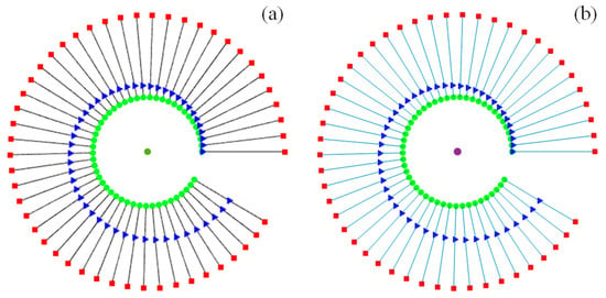
Figure 3.
Comparison of the attitudes of tethered satellites with a moving payload: (a) ANCF model and (b) two-piece dumbbell model [17]. The green circle, red square, and blue triangle represent satellite A, satellite B, and the payload, respectively.
In Figure 4, the orbital radius of satellite A, obtained from the ANCF model, is compared with that obtained from the two-piece dumbbell model. In this figure, the orbital radius from the current study, obtained using the ANCF, model is plotted as a red solid line, whereas the radius from the previous study [17], obtained using the two-piece dumbbell model, is plotted as a blue dotted line. As illustrated in Figure 4, the orbital radii derived from both models were nearly identical. This similarity is due to the payload moving at a low velocity and the small cross-sectional area of the tether, resulting in negligible mass effects from the tether. These comparisons validate the use of the proposed method for obtaining dynamic responses using the ANCF model.
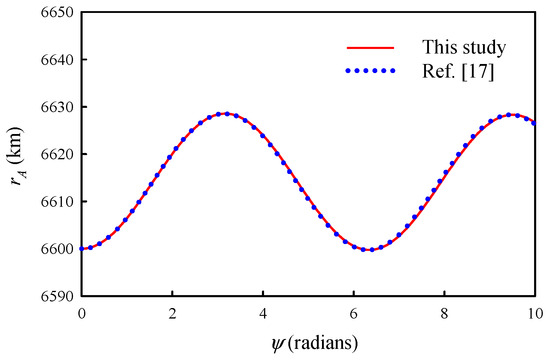
Figure 4.
Comparison of orbital radii: results from the current study using the ANCF model versus results from the previous study [17] using the two-piece dumbbell model.
We now proceed to analyze the dynamic responses of a tethered satellite system with a moving payload as it orbits the Earth in a circular orbit. For this analysis, the material properties and dimensions were the same as those used in the previous validation, except for the tether length, cross-sectional area, and payload speed. Unlike in the previous validation, the tether length and cross-sectional area used in this analysis were 20 km and 20 mm2, respectively, and the payload speed was 20 m/s.
The initial attitude of the tethered satellites with a moving payload is such that satellites and , along with the Earth’s center, are aligned in a straight line, as shown in Figure 5. In this figure, and represent the orbital radii from the Earth’s center to satellites and , respectively, with 6600 km and 6620 km. The initial tensile deformation of the tether was considered by taking into account the gravitational forces acting on the satellites and tether, as well as the centrifugal force resulting from the orbital motion around the Earth. Assume the payload starts at satellite A and moves to satellite B at a constant speed of 20 m/s. The angular speed for the satellite system to maintain a circular orbit when the payload is located at satellite can be determined under the condition that the total gravitational and centrifugal forces of the satellite system are equal. The angular speed is given by
where
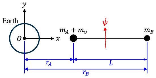
Figure 5.
Initial position of the tethered satellites with the moving payload.
According to the equation shown above, the satellite system shown in Figure 5 orbits in a circular path with an initial orbital angular speed of rad/s. Consequently, the initial linear velocities of satellites and , as well as the payload, were calculated by multiplying their orbital radii by the initial angular speed. Similarly, the initial velocities of the mass points on the tether were calculated to establish the initial conditions. The reference values for the material properties and dimensions used in the dynamic response analysis are summarized in Table 1. Unless otherwise specified, these values are used in the calculations presented in this section.

Table 1.
Reference values for the physical properties and dimensions used in the dynamic analysis.
First, the influence of the payload mass on the attitude of the tethered satellite system was analyzed. The dynamic responses of the satellite system were computed for various payload masses when the payload moved at 20 m/s, as shown in Figure 6. In Figure 6, similar to Figure 3, satellite A is represented by a green circle, satellite B by a red square, the moving payload by a blue triangle, and the tether by a black line. These symbols are used to describe the attitudes of the tethered satellite system with a moving payload in subsequent discussions. The changes in the attitude of the tethered satellite system during the transfer of the payload from satellite A to satellite B for various payload masses () of 10, 100, 200, 300, 400, and 500 kg are shown in Figure 6a,b,c,d,e,f, respectively. The attitudes of the satellite system at 10 different moments, spaced at equal time intervals during the transfer, are illustrated in Figure 6. The satellite system orbits the Earth in a counterclockwise direction, as indicated by the arrow in Figure 6a. When the payload mass was relatively small ( 10 kg), the tethers appeared almost straight, as shown in Figure 6a. However, as the payload mass increased, the tether deformation became more pronounced, as shown in Figure 6b–f. The payload moved clockwise relative to the line connecting satellites A and B, in contrast to the counterclockwise orbital motion. For relatively large payload masses, as shown in Figure 6e and f, the tether deformations become significant. As the payload approaches satellite B, the deformation becomes so severe that the tether experiences slack and rebound due to the payload’s tumbling, resulting in an unstable attitude.
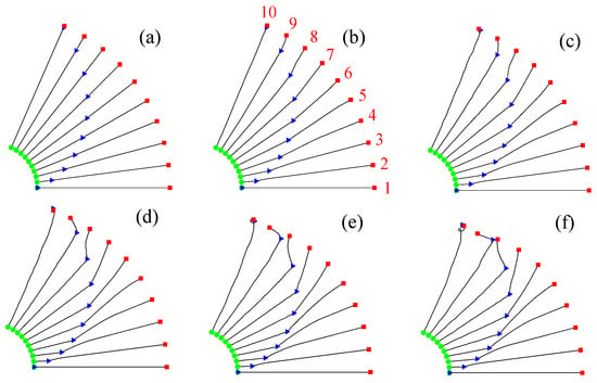
Figure 6.
Attitudes of tethered satellites for different payload masses as the payload moves from satellite A to satellite B: (a) 10 kg, (b) 100 kg, (c) 200 kg, (d) 300 kg, (e) 400 kg, and (f) 500 kg. The green circle, red square, and blue triangle represent satellite A, satellite B, and the payload, respectively.
When the payload is transferred from satellite B to satellite A at a speed of 20 m/s, the attitudes of the satellite system for various payload masses are shown in Figure 7. In this scenario, the initial conditions were set to maintain a circular orbit, with the payload initially positioned on satellite B. Similar to Figure 6, Figure 7 shows that tether deformation increased as the payload mass increased. For relatively large payload masses, specifically, 400 and 500 kg, significant tether deformations were observed as the payload approached satellite A (Figure 7e,f). Unlike in Figure 6, where the payload moves clockwise relative to the line connecting satellites A and B, Figure 7 shows the payload moving counterclockwise in the direction of orbital motion. This movement causes the tether to deform accordingly.
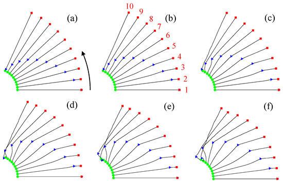
Figure 7.
Attitudes of tethered satellites for different payload masses as the payload moves from satellite B to satellite A: (a) 10 kg, (b) 100 kg, (c) 200 kg, (d) 300 kg, (e) 400 kg, and (f) 500 kg. The green circle, red square, and blue triangle represent satellite A, satellite B, and the payload, respectively.
The observed phenomenon in Figure 6 and Figure 7, where the payload deviates from the straight line connecting satellites A and B and causes tether deformation, is attributed to the Coriolis effect. The Coriolis force is an inertial force that acts on objects moving relative to a rotating reference frame. In these figures, the reference frame, centered on the Earth, rotates counterclockwise along the line joining satellites A and B. When the payload moved outward from the origin of the reference frame, as shown in Figure 6, a clockwise Coriolis force acted on it. Conversely, when the payload moved towards the origin, as shown in Figure 7, a counterclockwise Coriolis force acted on it. Since the Coriolis force is proportional to both the payload mass and speed, the tether deformation increased with these factors.
Next, the impact of payload speed on the attitude of the tethered satellites was analyzed. All material properties and dimensions used in the analysis, except for the payload speed, were the same as those listed in Table 1. The attitude of the tethered satellite system was investigated as the payload was transferred between satellites A and B at six different speeds, in the range of 10–60 m/s, in increments of 10 m/s. The attitudes during payload transfer from satellite A to satellite B at these speeds are illustrated in Figure 8, while Figure 9 shows the attitudes during the transfer from satellite B to satellite A. Both figures demonstrate that as the payload speed increased, the transfer time between the two satellites decreased, resulting in a reduction in the orbital distance of the satellite system. At a payload speed of 10 m/s, the tether connecting the satellites appears nearly straight (Figure 8a and Figure 9a). However, at a speed of 20 m/s, the tether appears as a broken line with the payload as its vertex (Figure 8b and Figure 9b). The direction of payload movement is clockwise when transferring from satellite A to satellite B, and counterclockwise when transferring from satellite B to satellite A, relative to the straight line connecting the two satellites. This phenomenon is attributed to the Coriolis effect. As the payload speed increased, the tether underwent greater deformation (Figure 7c–f and Figure 8c–f).
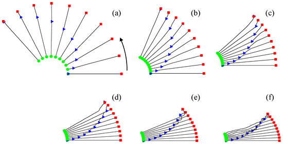
Figure 8.
Attitudes of tethered satellites for different payload speeds as the payload moves from satellite A to satellite B: (a) 10 m/s, (b) 20 m/s, (c) 30 m/s, (d) 40 m/s, (e) 50 m/s, and (f) 60 m/s. The green circle, red square, and blue triangle represent satellite A, satellite B, and the payload, respectively.
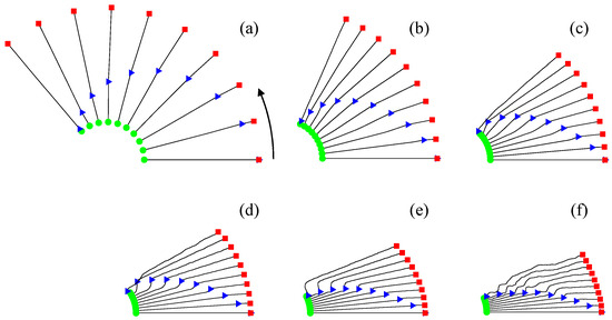
Figure 9.
Attitudes of tethered satellites for different payload speeds as the payload moves from satellite B to satellite A: (a) 10 m/s, (b) 20 m/s, (c) 30 m/s, (d) 40 m/s, (e) 50 m/s, and (f) 60 m/s. The green circle, red square, and blue triangle represent satellite A, satellite B, and the payload, respectively.
Finally, an analysis was conducted on the axial force exerted on the tether as the payload moved between satellites A and B. In a tethered satellite system where the two satellites were connected by a tether, differing orbital radii resulted in variations in gravitational and centrifugal forces. Consequently, the tether typically experienced a positive axial force; that is, a tensile force. As the payload moved along the tether, the Coriolis force, as previously described, acted on the payload, causing the lateral deformation of the tether. Therefore, the axial force was generated on the tether due to the combined effects of the gravitational, centrifugal, and Coriolis forces. This axial force can be computed by multiplying the Lagrange strain, expressed by Equation (6), by Young’s modulus and the cross-sectional area .
The changes in the axial force along the tether length were investigated as the payload, with a mass of 100 kg and speed of 20 m/s, moved between the two satellites at various attitudes. Figure 10 and Figure 11 illustrate the axial forces as functions of tether length when the payload travels from satellites A to B and B to A, respectively. In these figures, a position value of 0 km represents the location of satellite A, whereas a position value of 20 km represents the location of satellite B. The 10 graphs shown in these figures correspond to the axial forces for the 10 attitudes sequentially depicted in Figure 6b and Figure 7b. For instance, Figure 10a,b,c represent the axial forces along the tether length for attitudes 1, 2, and 3, respectively, as shown in Figure 6b.
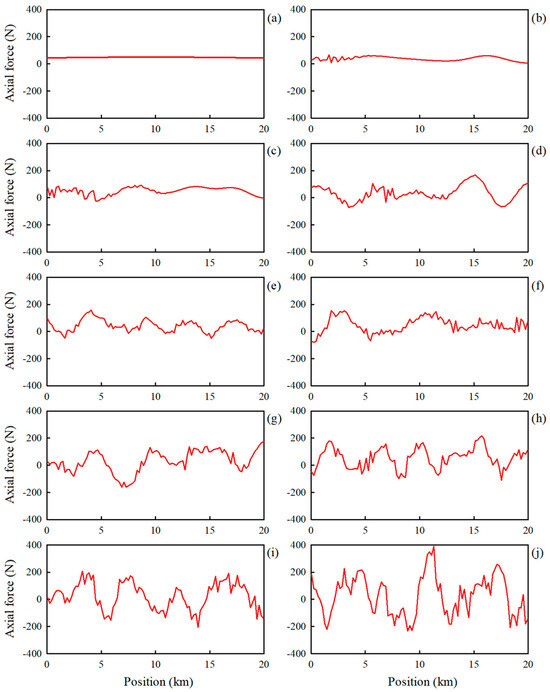
Figure 10.
Axial forces in the tether for various attitudes shown in Figure 6b: (a) attitude 1, (b) attitude 2, (c) attitude 3, (d) attitude 4, (e) attitude 5, (f) attitude 6, (g) attitude 7, (h) attitude 8, (i) attitude 9, and (j) attitude 10.
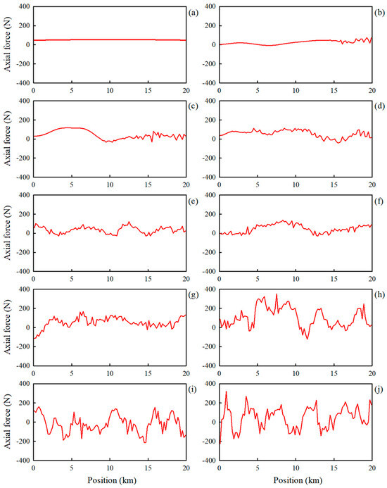
Figure 11.
Axial forces in the tether for various attitudes shown in Figure 7b: (a) attitude 1, (b) attitude 2, (c) attitude 3, (d) attitude 4, (e) attitude 5, (f) attitude 6, (g) attitude 7, (h) attitude 8, (i) attitude 9, and (j) attitude 10.
Figure 10 shows the axial forces along the tether length for the 10 attitudes depicted in Figure 6b as the payload moves from satellite A to satellite B. At attitude 1 in Figure 6b, where the payload was located at satellite A, a smooth and positive axial force is observed throughout the entire length of the tether, as shown in Figure 10a. This indicates that the entire tether was under tension. At attitude 2 in Figure 6b, where the payload has moved slightly towards satellite B, fluctuations in the axial force were observed near the payload position (approximately 2 km), as shown in Figure 10b. As the payload moved further towards satellite B, the magnitude of these fluctuations increased, causing the axial force to alternate between positive (tensile) and negative (compressive) forces (Figure 10c–j). Sections of the tether with a negative axial force, that is, a compressive force, were compressed axially, which can result in slack in the tether owing to lateral deformation. Another notable observation from Figure 10 is that the amplitude of the axial force fluctuations increased as the payload moved from satellite A to satellite B. The maximum axial force observed in Figure 10j is approximately 400 N.
Figure 11 shows the axial forces along the tether length for the 10 attitudes depicted in Figure 7b as the payload moved from satellite B to satellite A. Since the payload starts at satellite B, fluctuations in the axial force begin near the 18 km position at attitude 2 of Figure 7b (Figure 11b). These fluctuations expand towards satellite A at attitudes 3 and 4 (Figure 11c,d). Similar to the observations in Figure 10, Figure 11 shows that the amplitude of these axial force fluctuations increases as the payload approaches and eventually reaches satellite A. The amplitude of the axial force fluctuation in Figure 11j is smaller than that in Figure 10j because the Coriolis force is greater when the payload approaches satellite B than when it approaches satellite A.
5. Conclusions
In this study, we conducted a detailed analysis of the dynamic behavior of a three-body tethered satellite system, where a payload is transported along a flexible tether connecting two satellites. By employing the Absolute Nodal Coordinate Formulation (ANCF) to model tether flexibility, we captured important dynamics such as tether deformation, slack, and rebound—factors often overlooked in traditional dumbbell models. The findings and contributions of this study are summarized as follows:
- (1)
- We developed a comprehensive model of the three-body tethered satellite system using the ANCF. This model successfully illustrated the complex dynamics of the system, revealing how large deformations and the effects of tether slack and rebound are essential for realistic simulations of satellite behavior.
- (2)
- The discretized nonlinear equations of motion were derived using Lagrange’s equation, yielding a global nonlinear matrix-vector form. We solved these equations using the Newmark time integration method, computing dynamic responses that reflect the intricate behavior of the tethered system.
- (3)
- Our analysis highlighted the significant role of Coriolis effect in the trajectory of the payload. As the mass and speed of the payload increased, deviations from the straight line connecting the two satellites became pronounced, resulting in substantial tether deformation. Quantitatively, we observed that at higher payload masses (≥400 kg) and speeds (≥20 m/s), the tether deformation led to potential tumbling, inducing slack and rebound, and thereby risking system destabilization.
- (4)
- Initially, as the payload transitioned along the tether, axial force fluctuations were minimal. However, as it neared the other satellite, these fluctuations increased markedly, transitioning between tensile and compressive states. The quantitative results indicated that fluctuations in axial force could reach magnitudes exceeding 400 N, which has critical implications for tether design and operational strategies.
While this study provides valuable insights, several limitations exist. The ANCF model, while effective in capturing tether flexibility, may not fully account for other dynamic factors, such as nonlinear material properties or the effects of environmental disturbances (e.g., atmospheric drag). Future work should explore enhancements to the model by integrating these elements and conducting more extensive simulations that encompass a wider range of operational scenarios. Additionally, validating the model against experimental data could strengthen its applicability in real-world scenarios and improve its robustness.
Author Contributions
Conceptualization, J.C. and J.L; methodology: W.J. and J.L; software programming, Y.A. and W.J.; validation, Y.A. and J.L.; formal analysis, J.C. and W.J.; investigation, Y.A., W.J. and J.L.; resources, Y.A., W.J. and J.L.; data curation, Y.A.; writing—original draft preparation, Y.A. and W.J.; writing—review and editing, J.L. and J.C.; visualization, Y.A. and W.J.; supervision, J.C.; project administration, J.C.; funding acquisition, J.C. All authors have read and agreed to the published version of the manuscript.
Funding
This work was supported by a grant from the National Research Foundation of Korea (NRF), funded by the Korean Government (MEST) (NRF-2021R1A2C2007979).
Institutional Review Board Statement
Not applicable.
Informed Consent Statement
Not applicable.
Data Availability Statement
The original contributions presented in the study are included in the article, further inquiries can be directed to the corresponding author.
Conflicts of Interest
The authors declare no conflicts of interest.
References
- Wang, J.; Chen, X.; Liang, C. A comprehensive review of the dynamic behavior of tethered systems for space applications. Prog. Aerosp. Sci. 2024, 137, 100982. [Google Scholar]
- Anderson, K.S.; Hagedorn, P. Control of orbital drift of geostationary tethered satellites. J. Guid. Control Dyn. 1994, 17, 10–14. [Google Scholar] [CrossRef]
- Nakanishi, K.; Kojima, H.; Watanabe, T. Trajectories of in-plane periodic solutions of tethered satellite system projected on van der Pol planes. Acta Astronaut. 2011, 68, 1024–1030. [Google Scholar] [CrossRef]
- Zhao, G.; Sun, L.; Tan, S.; Huang, H. Librational characteristics of a dumbbell modeled tethered satellite under small, continuous, constant thrust. PI Mech. Eng. GJ Aer. 2013, 227, 857–872. [Google Scholar] [CrossRef]
- Sun, L.; Zhao, G.; Huang, H. Stability and control of tethered satellite with chemical propulsion in orbital plane. Nonlinear Dyn. 2013, 74, 1113–1131. [Google Scholar] [CrossRef]
- Kojima, H.; Taruoka, Y. Deployment control of a tethered satellite system for rendezvous with a target. Trans. Jpn. Soc. Aero. S. Sci. 2016, 59, 313–322. [Google Scholar] [CrossRef][Green Version]
- Liu, H.; He, Y.; Yan, H.; Tan, S. Tether tension control law design during orbital transfer via small-gain theorem. Aerosp. Sci. Technol. 2017, 63, 191–202. [Google Scholar] [CrossRef]
- Yu, B.S.; Xu, S.D.; Jin, D.P. Chaos in a tethered satellite system induced by atmospheric drag and Earth’s oblateness. Nonlinear Dyn. 2020, 101, 1233–1244. [Google Scholar] [CrossRef]
- Combot, T.; Maciejewski, A.J.; Przybylska, M. Non-integrability of a model of elastic dumbbell satellite. Nonlinear Dyn. 2021, 106, 125–146. [Google Scholar] [CrossRef]
- Liang, F.; Miao, L.; Tian, F.; Song, J.; Wang, N.; Hou, X. The effects of deployment friction on the dynamics of nonconductive space tethers. Acta Astronaut. 2024, 214, 567–582. [Google Scholar] [CrossRef]
- Zhao, G.; Sun, L.; Huang, H. Thrust control of tethered satellite with a short constant tether in orbital maneuvering. PI Mech. Eng. GJ Aer. 2014, 228, 2569–2586. [Google Scholar] [CrossRef]
- Zhong, Y.; Zhong, R. Dynamics, deployment and retrieval strategy for satellite-sail transverse formation with model inaccuracy. Aerospace 2022, 9, 602. [Google Scholar] [CrossRef]
- Sun, L.; Zhao, G.; Huang, H. Effect of mass variation on dynamics of tethered system in orbital maneuvering. Acta Astronaut. 2018, 146, 15–23. [Google Scholar] [CrossRef]
- Shan, M.; Shi, L. Comparison of tethered post-capture system models for space debris removal. Aerospace 2022, 9, 33. [Google Scholar] [CrossRef]
- Zhang, Y.; Jiang, X.; Bai, Z.F.; Guo, J.W.; Wei, C. Dynamics and rebound behavior analysis of flexible tethered satellite system in deployment and station-keeping phases. Def. Technol. 2022, 18, 509–523. [Google Scholar] [CrossRef]
- Bai, Z.; Jiang, X.; Fu, X. Investigation of the retrieval dynamics of the tethered satellites using ANCF-ALE variable-length element. IEEE Trans. Aerosp. Electron. Syst. 2023, 59, 1980–1988. [Google Scholar] [CrossRef]
- Jung, W.; Mazzoleni, A.P.; Chung, J. Dynamic analysis of a tethered satellite system with a moving mass. Nonlinear Dyn. 2014, 75, 267–281. [Google Scholar] [CrossRef]
- Kuo, Y.L. Dynamics and control of a tethered satellite system based on the SDRE method. Int. J. Aerosp. Eng. 2016, 2016, 610507. [Google Scholar] [CrossRef]
- Shi, G.; Zhu, Z.; Zhu, Z.H. Dynamics and control of three-body tethered system in large elliptic orbits. Acta Astronaut. 2018, 144, 397–404. [Google Scholar] [CrossRef]
- Shi, G.; Zhu, Z.; Zhu, Z.H. Libration suppression of tethered space system with a moving climber in circular orbit. Nonlinear Dyn. 2018, 91, 923–937. [Google Scholar] [CrossRef]
- Jung, W.; Mazzoleni, A.P.; Chung, J. Nonlinear dynamic analysis of a three-body tethered satellite system with deployment/retrieval. Nonlinear Dyn. 2015, 82, 1127–1144. [Google Scholar] [CrossRef]
- Shi, G.; Zhu, Z.; Zhu, Z.H. Dynamics and control of tethered multi-satellites in elliptic orbits. Aerosp. Sci. Technol. 2019, 91, 41–48. [Google Scholar] [CrossRef]
- Berzeri, M.; Shabana, A.A. Development of simple models for the elastic forces in the absolute nodal co-ordinate formulation. J. Sound Vib. 2000, 235, 539–565. [Google Scholar] [CrossRef]
- Li, Q.; Chen, D.; Liu, J. Control of a tethered satellite system with an elastic tether: Modeling and numerical simulations. Aerosp. Sci. Technol. 2023, 134, 107579. [Google Scholar]
- Santos, F.J.; Ferreira, M.P.; de Carvalho, A.G. Optimal control of tethered satellite systems with respect to propulsion and tether deployment. IEEE Trans. Aerosp. Electron. Syst. 2023, 59, 792–804. [Google Scholar]
- Wang, Y.; He, Y.; Yang, Y. Adaptive control of a tethered satellite system with uncertainties and external disturbances. Nonlinear Dyn. 2023, 114, 295–308. [Google Scholar]
- Newmark, N.M. A method of computation for structural dynamics. J. Eng. Mech. Div. 1959, 85, 67–94. [Google Scholar] [CrossRef]
- Shabana, A.A. Dynamics of Multibody Systems, 4th ed.; Cambridge University Press: Cambridge, UK, 2020. [Google Scholar]
Disclaimer/Publisher’s Note: The statements, opinions and data contained in all publications are solely those of the individual author(s) and contributor(s) and not of MDPI and/or the editor(s). MDPI and/or the editor(s) disclaim responsibility for any injury to people or property resulting from any ideas, methods, instructions or products referred to in the content. |
© 2024 by the authors. Licensee MDPI, Basel, Switzerland. This article is an open access article distributed under the terms and conditions of the Creative Commons Attribution (CC BY) license (https://creativecommons.org/licenses/by/4.0/).