Article

Exploring Non-Thermal Mechanisms of Biological Reactions to Extremely Low-Frequency Magnetic Field Exposure

1
Department of Electromagnetic and Biomedical Engineering, University of Zilina, 010 26 Zilina, Slovakia
2
Department of Applied Mathematics, University of Zilina, 010 26 Zilina, Slovakia
3
Department of Electrical, Computer, and Energy Engineering, College of Engineering and Applied Science, University of Colorado Boulder, Boulder, CO 80309, USA
*
Author to whom correspondence should be addressed.
Appl. Sci. 2024, 14(20), 9409; https://doi.org/10.3390/app14209409
Submission received: 4 September 2024 / Revised: 9 October 2024 / Accepted: 10 October 2024 / Published: 15 October 2024

Abstract

:
The increasing evidence regarding biological effects of exposure to an extremely low frequency magnetic field is of utmost interest not only to the scientific community, but also to legislative bodies and the public. However, the research in this field is full of controversial and inconsistent results, originated from a lack of widely acceptable physical mechanisms that could sufficiently describe the principle of such a field’s action. This experimental study addresses and points to possible sources of ambiguities via investigation of the ion parametric resonance mechanism at 50 Hz frequency. The chosen methodology incorporates exposure of the Saccharomyces cerevisiae yeast strain based on an established exposure protocol with special attention to the measurement of an applied time-varying magnetic field corresponding to the ion parametric resonance requirements. Subsequently, the differences in cell growth as a reaction to changes in magnetic flux density are evaluated and statistically analyzed. It is found that fluctuations in the magnetic field within the exposure setup need to be addressed properly, since this could have an impact on replication of the experiments and reliability of the results. Furthermore, comparison of two independently performed sets of 10 experiments showed statistically significant effects even in conditions that did not fulfill the requirements of the resonance theory, putting the validity and practical application of the ion parametric resonance model into question.

1. Introduction

It is very difficult to imagine the modern world without electricity. Over the past decades, the electromagnetic field (EMF) has become the main moderator between primary sources of energy and their final utilization on the public side as well as the main information agent. Economic growth resulted in significantly increased demand for modern technologies that make our lives easier. However, this demand multiplies the natural occurrence of EMF within the environment, leading to daily exposure of living beings to increasing values of electromagnetic quantities, which is documented by growing interest [1,2,3,4] in the assessment of such exposure.
Modern appliances are almost exclusively driven by EMF at a frequency of 50 or 60 Hz, which falls within the range of an extremely low-frequency electromagnetic field (ELF-EMF), according to WHO (1–300 Hz). ELF EMFs are present wherever electricity is generated and used (appliances or power lines), but also can be found within the EMF spectrum used in wireless technologies. It should be highlighted that the ELF EMF is not isolated in the wires. The wires shape the path of EMF in space, and EMF is widely distributed around them. Energy of the artificial ELF EMF is irretrievable for technologies, but it can have an impact on living organisms [5,6,7,8,9,10,11,12], where the biophysical and physiological processes have also the electromagnetic nature. Public health concerns have been underlined since 2002, when the International Agency for Research on Cancer (IARC) classified these fields as Group 3, corresponding to insufficient evidence of harmful effects, but later, based on growing scientific evidence [13,14,15], the IARC changed the classification of ELF EMF to Group 2B, corresponding to the possibly carcinogenic group for people. This classification originates from conclusions applied to ELF MF, stating that:
“There is limited evidence in humans for the carcinogenicity of extremely low-frequency magnetic fields in relation to childhood leukaemia.
There is inadequate evidence in humans for the carcinogenicity of extremely low- frequency magnetic fields in relation to all other cancers.
There is inadequate evidence in experimental animals for the carcinogenicity of extremely low-frequency magnetic fields.” [13]. If the effects of these weak fields were confirmed, it would have an adverse and at the same time economic impact on the general public.
The exposure to EMF can be investigated from various perspectives, commonly taking into account the electric and magnetic parts separately considering corresponding physical quantities and properties—mainly electric intensity, magnetic flux density, frequency and exposure duration. Assessment of biological reactions to external EMF is usually bound to energy absorption resulting in so-called thermal effects, which are relatively known and well described [16,17,18]. However, under certain circumstances and EMF levels, the thermal effects are insufficient to describe the behavior of biological objects exposed to EMF [19]. This is very common in the area of ELF EMF, where the wavelength is simply too long in comparison with biological objects to cause any significant thermal effect. To address this problem, the nonthermal description of EMF action needs to be considered, especially when the magnetic component of ELF EMF is investigated.
At the molecular level, several theories describing the biological effects of an extremely low-frequency magnetic field (ELF MF) have already been proposed, among which the theory about reactive oxygen species (ROS) and free radical pairs [20,21,22,23] is one of the most popular explanations of ELF MF nonthermal effects, postulating that it is the increase in the amount of ROS that causes various pathological processes and diseases in the body. Current extensive research and growing evidence [23,24,25,26,27,28,29] from observed biological effects on various cell lines helps strengthen the reliability of the radical pairs mechanism affecting the ROS, despite the fact that detailed and exact physical description is still an object of investigation.
However, the focus of this paper is on the mechanism of ELF MF action called ion parametric resonance (IPR), behind which are also a non-negligible body of contested studies [30,31,32,33,34,35,36,37,38,39,40,41]. The model describes the mechanism of a parallelly combined time-varying (AC) and static (DC) magnetic field (MF) action on specific ions in biological structures (cell membrane proteins). The theory of IPR has been developing since the publication by V.V. Lednev in January 1991 [30]. The Russian physicist, based on the ion cyclotron resonance model [31], proposed the parametric resonance model where it is considered that ions bound to proteins (Ca2+, K+, and/or Mg2+) behave as isotropic coupled oscillators. These ions can serve as primary targets for AC MF [30,31]. Lednev’s theory shows that the probability P of the AC MF biological effect is described by the square of the Bessel function of the first order—J1:
P = J 1 2 ( B A C B D C ) ,
Accordingly, the resonance frequency formally corresponds to the cyclotron frequency [31]:
f A C = 1 n q m B D C 2 π ,
where fAC is the frequency (in Hz) of the time-varying magnetic field, n = 1, 2, 3… represents the number of corresponding subharmonics, q is the electric charge (in C) of a specific ion, m is the mass of the ion (in kg), and BDC is the induction value of the static magnetic field in (T).
The maximal effects should be achieved when
B A C = 1.8 · B D C ,
For the case of weak BAC (less than 10 μT), it has been shown experimentally that Lednev’s model can describe the biological effects (amplitude and frequency dependences) of an AC MF tuned to the Larmor precession frequency for some nuclear spins as 1H, 39K, 55Mn, 31P, 35Cl, 63Cu, and 23Na [40]. This model permits the calculation of the AC MF parameters necessary, on one hand, for achieving a maximal effect and, on the other hand, at known experimental AC MF parameters, for the identification of primary targets [32,33,34]. An experimental confirmation of this assumption in Lednev’s model is provided by the results presented in [37,40], using two test systems: regenerating planarians and gravitropic reaction of plants. The results of Belova et al. [40] presented in the Journal of Biophysics 5 suggest that for fields of industrial frequencies (50 and 60 Hz), the primary targets are the spins of nuclei of hydrogen atoms. The role of magnetic flux’s density amplitude is detailed in an article from Belova, N. A. et al. [41], providing evidence to suggest that extremely weak alternating magnetic fields (EW AMF) with BAC values in the µT, nT and even pT range can produce statistically significant effects in biological systems. It should be noted that most EW AMF experiments are performed in the presence of a static geomagnetic field (GMF) component. Available theoretical and experimental data confirm that an AC MF with a frequency of 50/60 Hz can induce biological effects at a magnetic flux density value of BAC > 10 µT, while the possibility of biological effects of EW AMF with BAC < 10 µT remains questionable. However, several results have also demonstrated the effect of BAC < 10 µT on biological systems [42].
Despite the detailed mechanism descriptions, investigations and experimental evidence, there is no general scientific acceptance of any physical mechanism of ELF MF nonthermal action on biological samples. This is one of the main gaps in knowledge and suitable areas for future research reported also by the ICNIRP in [43]. Studies in this field often report selectivity of biological reactions related mainly to the frequency, amplitude, length of exposure and to the sensitivity of different cell lines [44]. However, results typically remain inconsistent, with questionable repeatability and relevance. One of the common aspects of the studies in this research field is lack or absence of the MF background measurement or monitoring within the exposure area. This is another possible reason why the effect of these fields remains controversial, but still a challenging research area.
This work tries to help address the problem with ambiguous results, focusing on the precise implementation of the chosen methodology and experimental protocol setup incorporating exposure system optimization with a focus on static MF measurement within the incubator and exposure system. The research aim is verification of IPR theory via continuous exposure of the yeast strain Saccharomyces cerevisiae to a time-varying ELF MF. As is shown further, setting the exposure conditions to meet the IPR demands within the laboratory environment is not an easy task, which can not be achieved without accurate measurements of magnetic background as well as monitoring of relevant quantities within the microbiological experiments. After sufficient optimization of the exposure setup and in accordance with the chosen methodology, a significant set of experiments is performed to obtain data for subsequent statistical analysis, from which the conclusions regarding the biological effects of the chosen ELF MF are drawn, together with a discussion about the need for MF monitoring as a crucial part of IPR mechanism (as well as any other) validation.

2. Materials and Methods

The methodology was established to perform the continuous 7 h exposure of Saccharomyces cerevisiae cell cultures to 50 Hz AC MF reflecting the IPR conditions through accurate and precise measurement of magnetic flux density. Two sets of laboratory experiments were conducted using a single factor and multiple groups simultaneously to validate the scientific theory related to how cells react to the changing ELF MF with the grid frequency. The details regarding exposures of each experimental set are presented within Table 1. To ensure precision and reliability in the findings, the experiment was replicated 10 times in each experimental set with consistent ambient conditions, an identical protocol, and the same experimental equipment.

2.1. Configuration for Continuous Exposure

To simulate an AC MF emitted by real-life sources like transmission lines under laboratory conditions, the presence of a special exposure configuration is deemed necessary. The capability to control exposure conditions, ensure the proper positioning of biological objects, and minimize potential biomedical errors should be encompassed by this system. To address all the mentioned demands, the entire exposure configuration (Figure 1) was composed of the following main components: an incubator Q-Cell 240/40 (POL LAB, Poland), metal shielding and two identical cylindrical coils, each with a height of 1000 mm and internal diameter of 135 mm, for exposure and control samples. The supporting structures of both coils were constructed from polytetrafluoroethylene, and each supporting structure was wound with a total of 912 m of enameled copper wire with a diameter of 1 mm, comprising 2000 turns. The precise placement of experimental samples, glass vials, within the coil cavities was defined by a polyethylene support structure consisting of 4 guide rails and 5 shelves in positions E to A. The samples were uniformly distributed within each coil’s cavity, maintaining each placement 190 mm apart, with the edge sample positions (E and A) located 100 mm from the respective edge of the coil. The level height of the culture medium placed in the bank is also considered to determine the position from the edge of the coil. To shield the control samples from the generated time-varying electromagnetic field, a 3 mm thick metal sheet, primarily composed of iron (over 96% iron content), with dimensions of 1000 mm in length and 160 mm in width, was positioned in the center of the incubator between the coils.
The alternating magnetic field was generated by an exposure coil driven by harmonic current sourced from the RIGOL DG4162 generator (manufactured by RIGOL Technologies, Suzhou, China). This signal was subsequently amplified using a HUBERT A1110-16 linear amplifier (manufactured by Dr. HUBERT GmbH, Dietrich-Benking-Strasse 41, Bochum, Germany), while the current value was measured by a 6-digit digital multimeter, the Agilent 34401A (produced by Keysight Technologies, Colorado Springs, CO, USA).

2.2. Exposure Settings with Nonspecific Conditions

The parallel combination of an AC MF and a static one is supposed by the IPR theory of the non-thermal biological impact of ELF MF. Within this set of experiments, the GMF was considered as the static component. Measurement of geomagnetic flux density in the exposure configuration was conducted using a magnetometer equipped with the three-axis electronic compass HMC5883L (Honeywell International, Inc., Charlotte, NC, USA). This sensor was selected due to its affordability, a suitable measuring range of ±800 µT, and a resolution of up to 0.5 µT, along with a high level of accuracy of 2° guaranteed by the manufacturer. Furthermore, anisotropic magnetoresistive technology was employed by this sensor to ensure axial sensitivity and linearity. The fundamental functionality revolved around the conversion of the Earth’s magnetic field into a voltage differential on three axes, denoted as x, y, and z in the Cartesian coordinate system.
Initially, the magnetic flux density of the static MF background was measured at the center of the incubator without the presence of shielding and coils. This measured value amounted to 39 µT and was subsequently employed to calculate the values of the alternating component of the magnetic flux density, B A C (as per Equation (4)), driven by sinusoidal harmonic current (as per Equation (5)). In accordance with Belova et al.’s [35] methodology, the cyclotron resonance frequency f C , as listed in Table 2, of various ions was calculated in agreement with the IPR theory (as per Equation (6)). These ions are commonly found in the eukaryotic cells of Saccharomyces cerevisiae and are essential for their normal function. Considering the charge-to-mass ratio q m provided for each ion in Table 2, it is possible to compute their respective cyclotron frequencies. The frequency of Mg2+ cyclotron motion is approximately 50 Hz, which aligns with the frequency of the alternating component of EMF under investigation in this study, indicating that the experiments were specifically targeted at this ion. Assuming the 39 µT as static component, the alternating MF was set to 70.2 µT to achieve the highest possible biological response, and under such settings and conditions, the initial set of experiments was performed with the belief that IPR conditions had been met.
The exposure settings were thus characterized by
B A C = 1.8 · B D C = 1.8 · 39 · 10 6   T = 70.2   μ T
i t = 0.112   A sin ( 2 π f C   t )
where
f C = f A C = 1 n 1 2 π q m B D C = 50   H z
The control samples were cultivated in the second coil system, to assure identical positioning, air conditions and comparable temperature conditions, but without any excitation signal. The magnetic field of the control coil was also measured and could be characterized by values in Table 3 (evidence can be found in the Supplementary Files, where the measurements of static MF within the incubator under various scenarios are presented), meaning that the control samples were exposed only to naturally occurring static MF within the incubator.
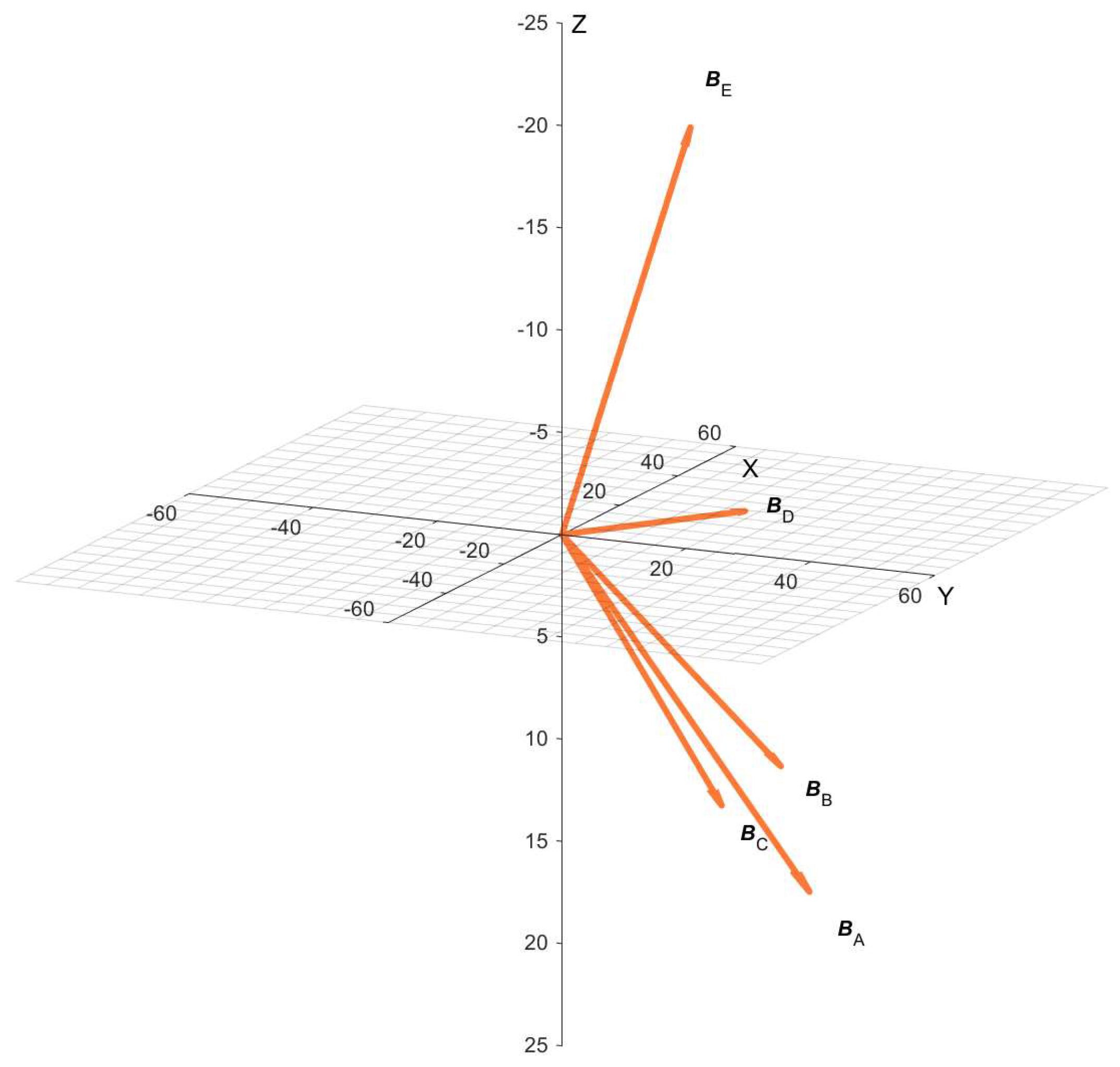
However, from the subsequent GMF measurements, it is evident that the conditions of the IPR theory were not fulfilled during the exposure. The control measurement of the geomagnetic flux density B D C and the parameter α, which refers to the angle between the static and generated AC magnetic field (which should be in parallel orientation), was carried out individually for each position of the exposure coil sample in the complete experimental setup. The results of these measurements are presented in Table 3, with the sensor being rotated in the same manner for each measurement. These measurements have shown the changes in the distribution of the static magnetic field that were induced by the metal structure of the incubator and metal shielding. Since the absolute value of the Earth’s magnetic flux density differed in all sample positions (E–A), the condition of constancy was not maintained within the cavity of the exposure coil. Simultaneously, the condition of collinearity between the vectors of the static and alternating components of the magnetic flux density also had not been met, which is graphically illustrated in Figure 2.
The samples were thus exposed to the nonspecific time varying MF, consisting of the superposition of a 70.2 µT alternating component and respective static component corresponding to the exact position within the exposure setup (specific values are summarized in Table 2). These findings were addressed within the second set of experiments, where the measures for compensation of static MF were applied.

2.3. Artificial Settings of IPR Conditions

With the aim of verifying the physical mechanism of IPR, the second set of experiments is consequently conducted under artificially generated conditions established by a non-harmonic electric current feeding the exposure coil, to compensate for fluctuations in the static magnetic field background and maintain its consistency and orientation. The driving signal consists of a direct current component, responsible for generating a DC MF component within the coil cavity, and a harmonic component, responsible for producing a harmonic AC MF component with frequency of 50 Hz. The level of the DC component is adjusted to a degree where any fluctuations in the distribution of the geomagnetic field can be disregarded, which resulted in the excitation current described in Equation (7). If the artificial conditions are set to 5 times the GMF, the resonance conditions should be secured.
The ion cyclotron frequencies listed in Table 4 are determined based on the magnetic flux density measured at the laboratory’s center, which is B D C = 50.92 µT. When the static component of magnetic flux density is increased to 5 times the magnitude of the basic GMF, resonance can be induced at a cyclotron frequency that is 5 times higher, owing to the linear relationship between the parameters (as described in Equation (2)), or at other additional subharmonic frequencies n specific to the ion in question. Following this adjustment, the static magnetic flux density, 5 times the basic value 5 · B D C , corresponds to 254.6 µT, and the corresponding cyclotron frequency 5 · f C for potassium ion K+ targeting is 100 Hz. Consequently, resonance occurs at the 2nd subharmonic frequency: f C ( 1 / 2 ) = 50   H z .
i t = 0.107   A + 0.284   A sin ( 2 π f C 1 / 2   t )
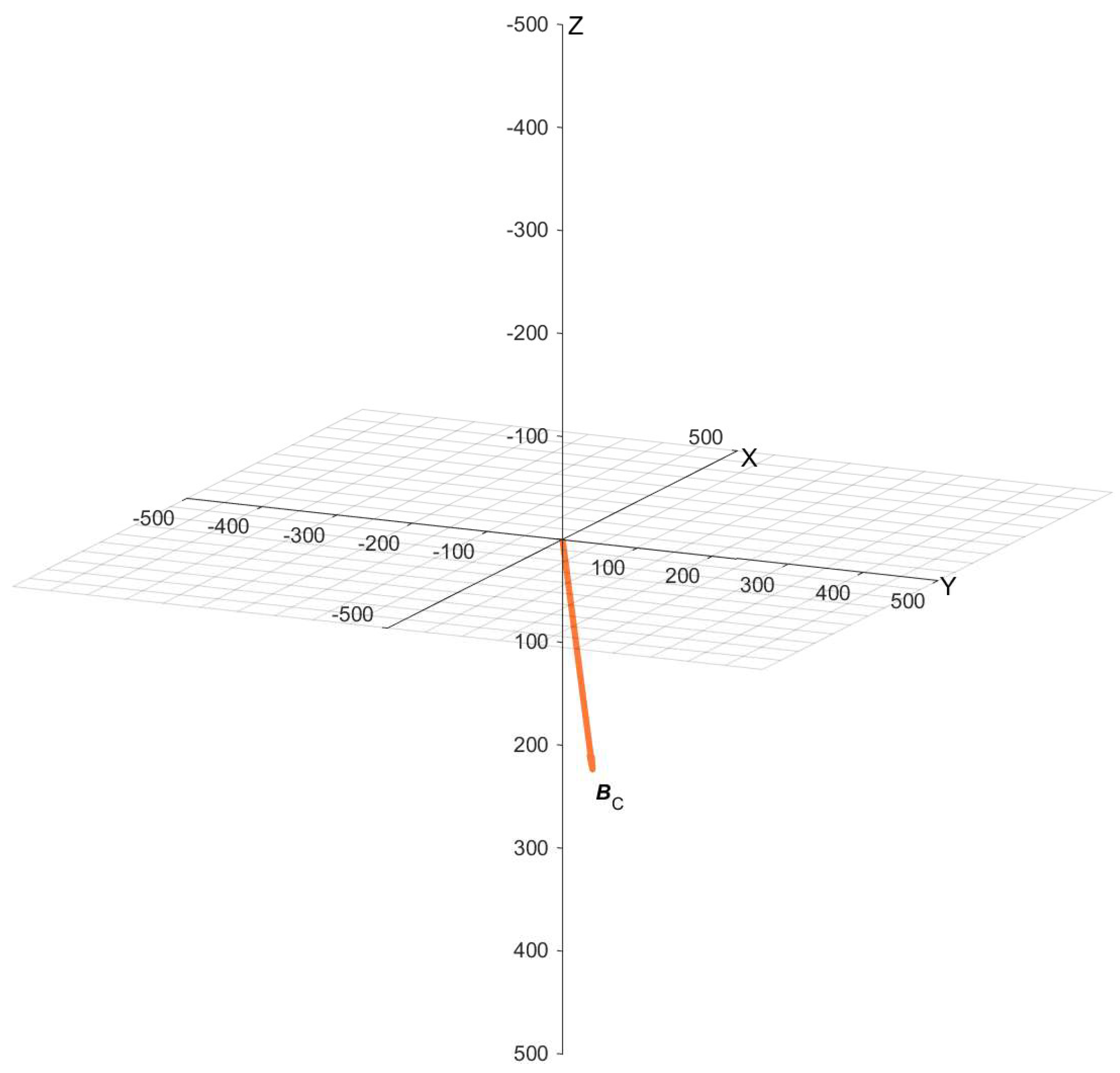
Considering the IPR model, it is imperative that the vectors of the static and alternating components of the MF are combined in parallel. To achieve this, measurements using the designed magnetometer were performed at each of the sample’s positions. As an example, shown in Figure 3, the measured angle α reached a value of 9.66° in position C within the exposure coil powered by the non-harmonic current producing a DC component five times the magnitude of the GMF. This deviation can be regarded as insignificant.
The final requirement is that the maximum biological effect should be achieved when the magnitude of the alternating component is 1.8 times higher than the magnitude of the DC MF component, which can be expressed as follows:
B A C = 1.8 · B D C = 1.8 · 254.6 · 10 6   T = 458.28   μ T .
The control samples were again cultivated in a second coil system, with conditions identical to those applied during the first set of experiments.

2.4. Temperature Monitoring

Temperature plays a critical role in the growth and reproduction of yeast. Yeasts are highly sensitive to temperature variations, and such fluctuations can significantly impact their growth rate. The optimal temperature range for yeast growth and multiplication varies depending on the yeast strain and the specific conditions of the growth medium. However, generally, a temperature range of 30 °C to 35 °C is considered ideal for the initial rapid development of yeasts [45]. Therefore, it is essential to meticulously monitor and control temperature during yeast-related experiments to ensure precise and reproducible outcomes.
To address this need, a device was applied for monitoring temperature at the separate exposure and control sample points during irradiation experiments, recording the results at 10-minute intervals onto a memory medium. The DS18B20 temperature sensor, manufactured by Dallas Semiconductor in the USA, was used for this purpose. It was chosen for its capacity to power multiple sensors simultaneously using only three wires, two for power and one for data transfer.
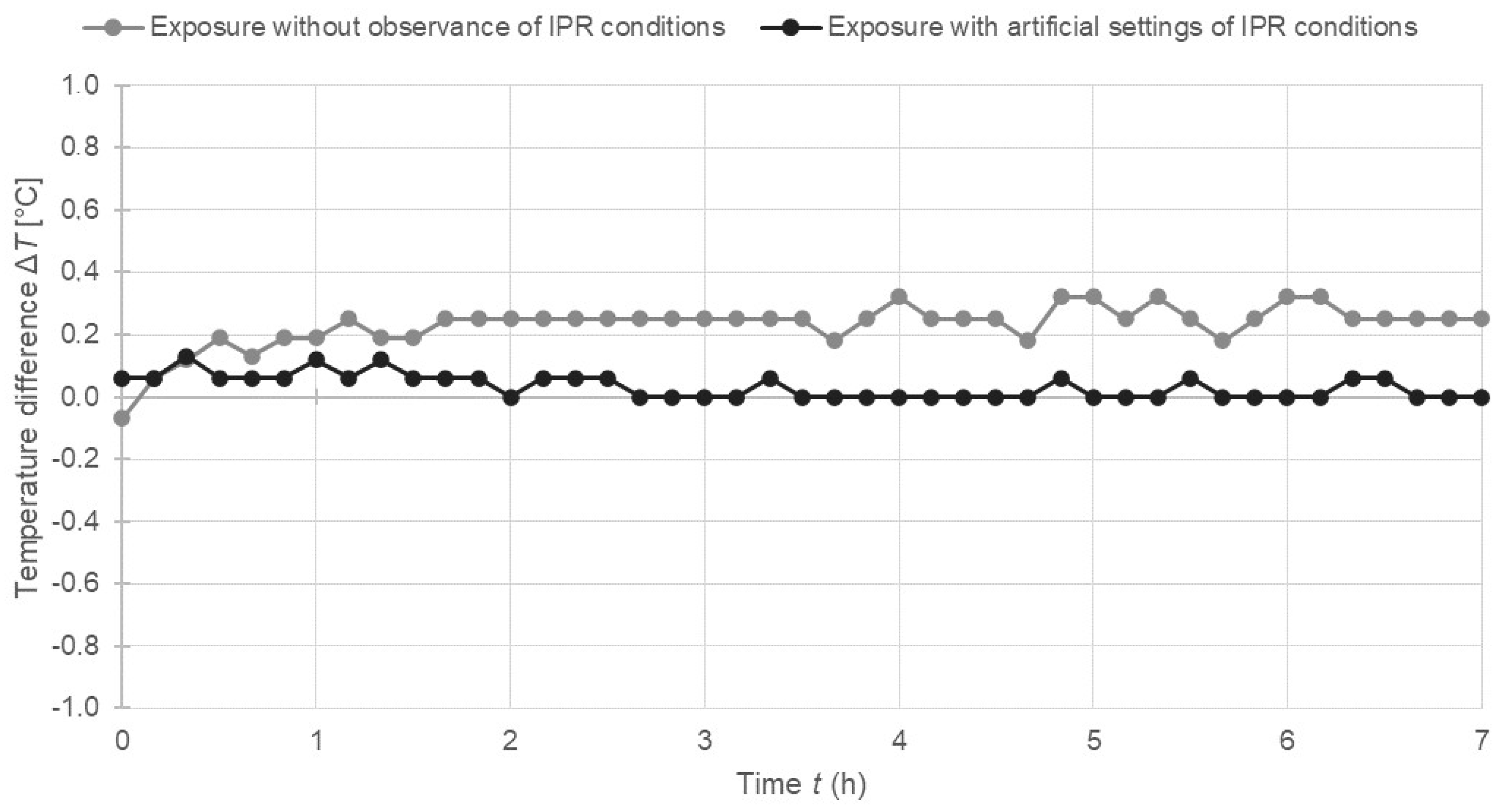
Temperature monitoring was conducted in all experimental sets. The temperature was measured from the outside of the Erlenmeyer flask at each position of the biological sample with the intention not to affect the cultured cells in other than a magnetic way. However, during our previous study [44], the temperature measurements were also applied directly from the medium with no differences between the measurements performed from the outside of the flask. Figure 4 represents an example of temperature monitoring at position C within the coils situated in the incubator, which was set to 30 °C. Temperature data were collected for two different experiments: one involving EMF exposure with nonspecific conditions and the second involving exposure with artificially set IPR conditions. In both groups, the temperature difference between the coils remained less than 0.3 °C. This variation can be deemed negligible with respect to works [46,47], implying that temperature had no discernible impact on the growth and proliferation of Saccharomyces cerevisiae yeast during the exposure experiments. This was confirmed also by our preliminary work presented in [48], where the control vs. control experiments were performed with both coils unexcited by the electromagnetic signal, but with similar temperature differences measured as in the case described herein. The experiments resulted in statistically no significant effect.

2.5. Experimental Protocol

In this research study, Saccharomyces cerevisiae yeast cells BY-4741, MATa were employed as a model organism due to their eukaryotic nature, resembling human body cells in composition, including a nucleus and other organelles, and sharing 23% homologous genes. They offer additional advantages such as rapid reproduction, a short life cycle, cost-effectiveness in cultivation and storage, and suitability for acidic conditions with high sugar content that inhibits bacterial growth and prevents contamination.
The experimental protocol was established on the basis of the one specified in our previous studies [44,48]. The manipulation and preparation of experimental yeast samples were exclusively carried out within a laminar box Streamline SCR–2A1 Cabinet (manufactured by Esco Micro Pte. Ltd., Singapore). This cabinet is equipped with a light source, a UV lamp, and a specialized HEPA air filter that ensures the sterilization of the environment. The experimental solution itself consisted of pre-cultured yeast (cultured 24 h at room temperature prior to each experiment) diluted into YPD substrate comprising 1% (w/v) yeast extract, 2% (w/v) peptone, 2% (w/v) D-glucose and 95% distilled water. Ten samples were prepared in this manner, divided into 5 exposed and 5 control samples. Following homogenization of the solution on a shaker, a sample was extracted from each flask using a micropipette to determine the cell count.
The quantification of cell numbers was performed using hemocytometry, a method that involves the use of a microscope, a calibration slide with a grid—a Bürker chamber, and a device for photographic recording. Subsequently, the samples were placed within the coil cavities and introduced into the incubator. Following exposure, the samples underwent another quantification assessment. The growth coefficient X was employed to assess the response of the biological system, calculated as the relative ratio between the partial growth coefficients of the exposed and control samples at a particular position (E–A) of the coils:
X = E C ,
where E represents the partial growth coefficient of the exposed sample:
E = i = 1 N E a f t e r ( i ) i = 1 N E b e f o r e ( i )   ,
where Eafter stands for the number of cells after the experiment, while Ebefore denotes the number of yeast cells before the experiment for the exposed sample. C represents the partial growth coefficient for the control sample:
C = i = 1 N C a f t e r   ( i ) i = 1 N C b e f o r e   ( i )  
The count of cells for the control sample after and before the experiment is indicated by parameters Cafter and Cbefore. The parameter N signifies the quantity of Bürker chamber squares, which, in this instance, amounted to 6.

2.6. Statistical Analysis

The hypothesis under investigation posited that a grid frequency EMF has a biological influence. This hypothesis was scrutinized during the statistical analysis of both groups of resulting data obtained after 7 h of EMF exposure:
  • without observance of IPR conditions,
  • with artificial settings of IPR conditions.
The parameters used in the statistical examination of these hypotheses encompassed the growth coefficient of the exposed sample denoted as E, which was derived from Equation (10), and the growth coefficient of the control sample designated as C, defined by Equation (11). A two-sample Student’s t-test was employed to determine whether there were disparities in the means of two distinct populations.
A significance level of α = 0.05 was used to assess all hypotheses. The decision regarding the null hypothesis depended on the p-value: H0 was retained when the p-value was ≥0.05, but rejected when the p-value was <0.05.

3. Results

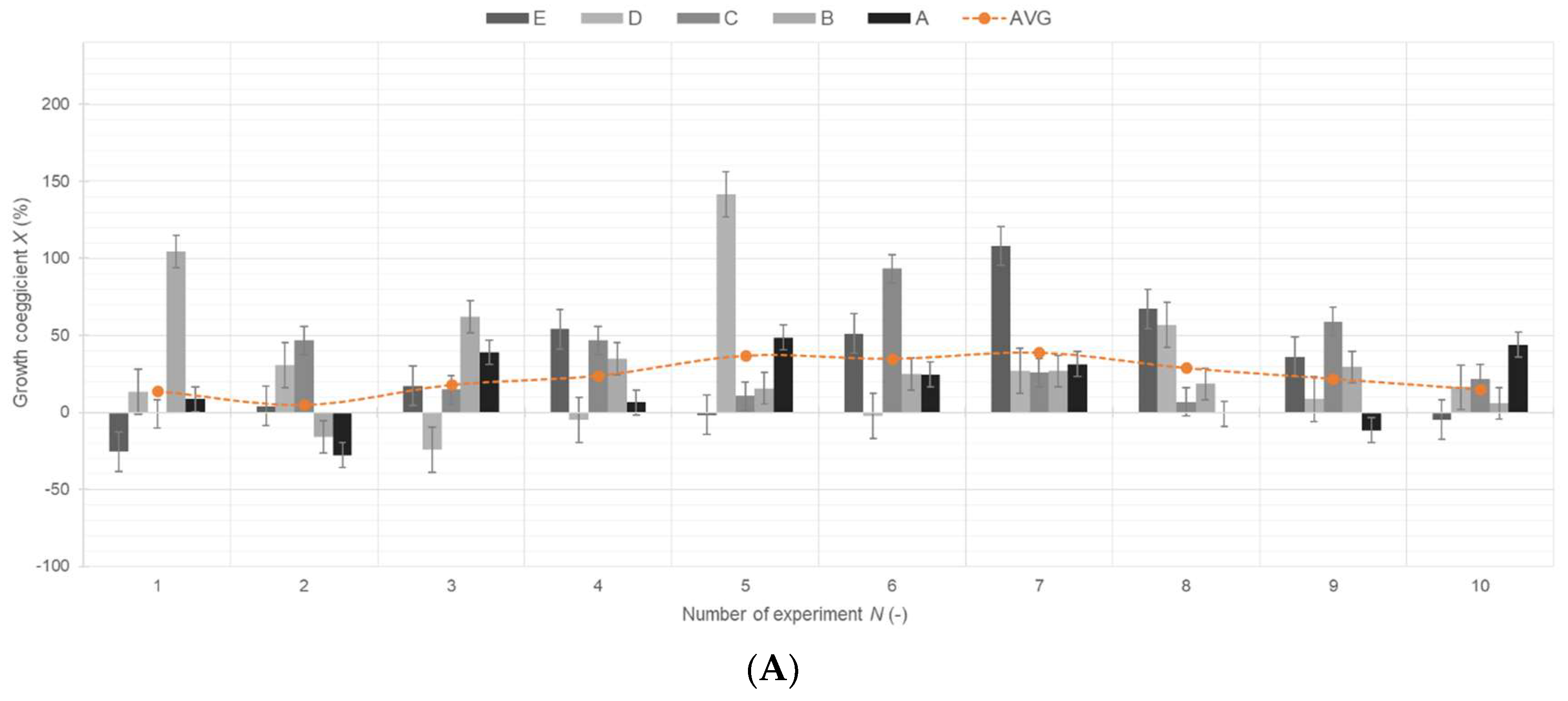
To assess the biological system’s response, parameter X was utilized, as defined in Equation (9). To enhance result interpretation, the formula was subsequently transformed into percentages. When X equaled one, there was no alteration in the cell growth state, and the corresponding percentage remained at zero. However, when the applied field stimulated the growth of cells, the effect coefficient yielded a positive percentage value. Conversely, if the field inhibited the cellular growth, the coefficient fell within the range of negative values.
The outcomes of the experiments are graphically presented in Figure 5 after MF exposure without adherence to IPR conditions (1st set of experiments) and Figure 6 following 7 h of MF exposure with artificial IPR conditions set (2nd set of experiments). These figures also illustrate the average growth coefficient for each experiment, contingent upon the sample’s position within the coil cavity. In both cases, the arithmetic mean predominantly fell within the positive value range, indicating a likely stimulation effect. Error bars represent data uncertainty or variation, calculated as the standard error from all 10 experiments at each sample position (E–A).
The deviation of the first four experiments within the results presented in Figure 5 and Figure 6 could be due to the aging of original strain cultures, from which the experimental solution was diluted.

3.1. Results of Statistical Analysis of Experimental Data

Statistical significance of observed results is presented in Table 5, which displays summary statistics for both resulting data groups further divided to exposed and control population, including count, average, standard deviation, standard error, minimum and maximum. To add to the scientific comparability of the obtained data, the values of Cohen’s d and Glass’s delta were calculated and are presented in Table 5, as well. Both values point to the medium size effect.

Comparison of Means

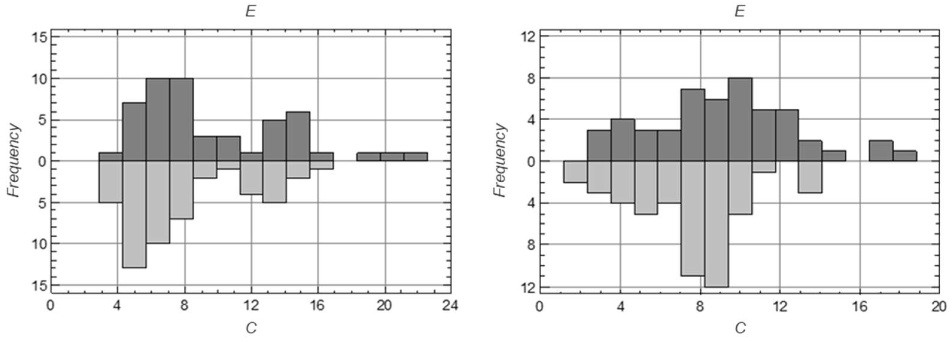
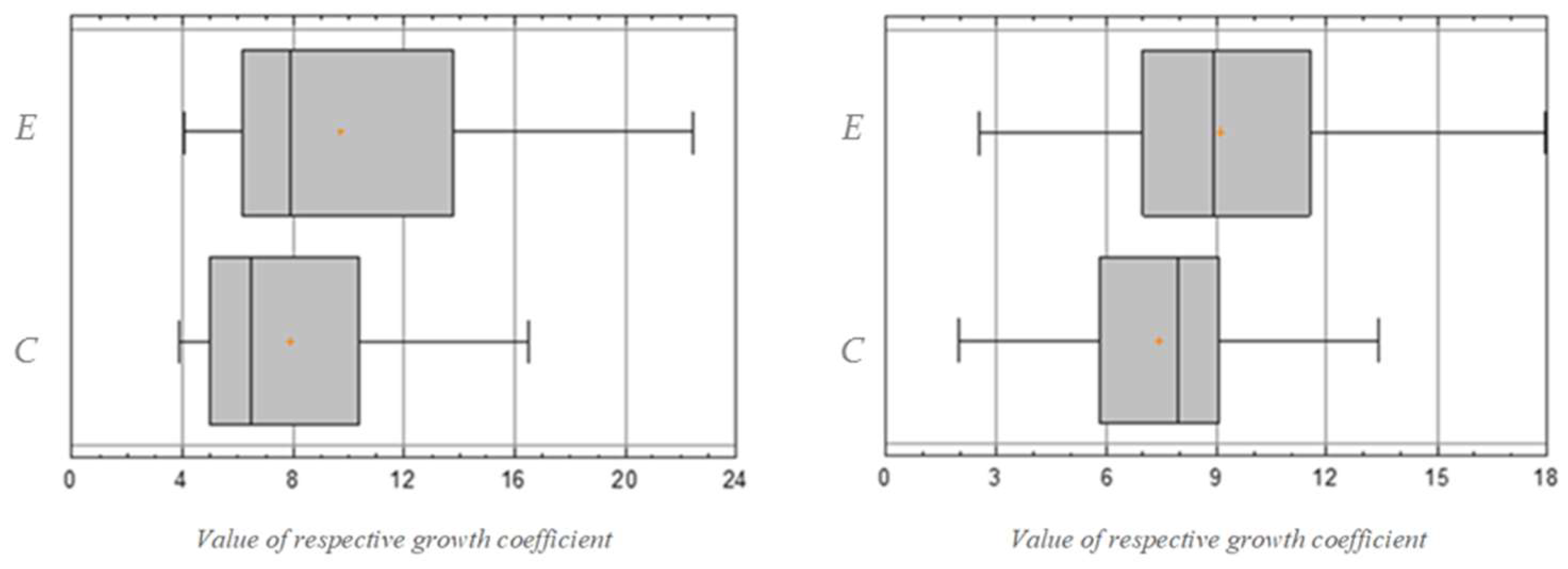
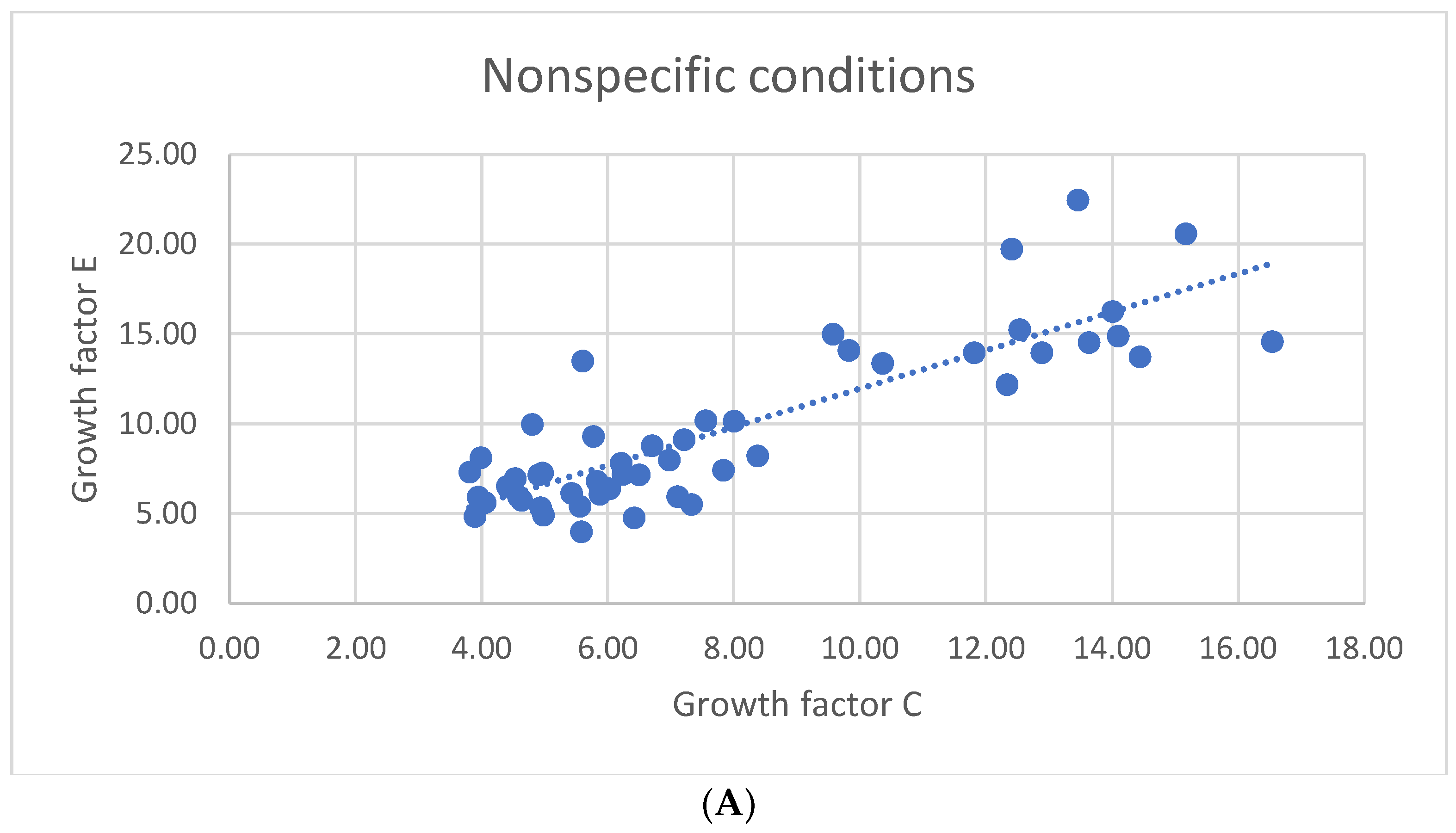
A two-sample two-tailed Student’s t-test was utilized to compare the mean values of the exposed and control samples, with the assumption of equal variances in their normal distributions. The results for both examined groups are displayed in Table 6. The null hypothesis H0, which postulated that the growth coefficients of the exposed and control samples are identical, was countered by the alternative hypothesis H1, which suggested a statistically significant disparity between the growth coefficients of these two sample sets. The calculated p-values were found to be below 0.05, resulting in the null hypothesis being rejected in favor of the alternative. Furthermore, statistically significant distinctions in the growth coefficients between the exposed and control samples within both examined groups were revealed by both the frequency histograms (depicted in Figure 7) and the box plots (illustrated in Figure 8). Respective scatterplots are presented in Figure 9. This mathematical analysis affirmed the impact of grid frequency MF after exposure, whether IPR conditions were not observed or when artificial IPR conditions were applied. Consequently, it is likely that the ion parametric resonance model may not serve as an accurate non-thermal explanation for the influence of a low-frequency electromagnetic field on biological systems.

4. Discussion and Conclusions

Increasing levels of artificial EMF as one of the environmental physical factors should be taken into consideration in various areas related to public health or environmental safety, and increasing the knowledge base regarding the mechanisms of EMF action on biological structures is a fundamental step towards safety and sustainability.
After studying the state-of-the-art research papers, we decided to perform our own experiments, discuss partial results in national and international conferences, and optimize the exposure setup in accordance with newly gained knowledge of mechanisms explaining how ELF-EMF can interact with cell organisms. Implementing sensorics monitoring technologies within the research methodology and processes, to cover all aspects that could possibly affect consistency, repeatability and reliability of results, was of utmost importance to address the diverse opinions of the scientific community related to quantum physics, cell biology, chemistry and bioelectromagnetism. Based on gained experience and experimental evidence [38,44,48,49,50,51,52,53,54,55], confirmed also by this study, it could be concluded, that statistically significant responses of biological system exposure to ELF MF could be observed even under conditions that do not meet the IPR requirements, as stated by the first set of experiments with the nonspecific conditions.
As the IPR model elucidates how exposure to MFs can induce cellular stress (e.g., stress gene upregulation), metabolic changes (e.g., alterations in fermentation), alterations in cell division and reproduction, genetic regulation (gene expression alteration), and cumulative effects over time, as presented in Figure 10, maintaining uniformity in the static MF within the coil and ensuring it remained perpendicular to the time-varying electromagnetic field was of utmost importance. Because of that, a second, modified set of experiments was performed, with the artificial settings of IPR conditions applied.
However, the main contributions of this study are not only in its extension of experimental evidence in the context of ELF MF impact on biological systems at the cellular level, but also in its MF measurements within the exposure setup. The performed measurements revealed the difficulties related to precise fulfillment of the physical conditions of the IPR mechanism even within the laboratory environment, putting into question its practical utilization as the mechanism that can explain the increasing evidence [5,6,7,8,9,10,11,12,13,14,25,26,27,28,29,44,48,49,50,51,55,56,57,58] of biological reactions under ELF MF exposure in real life. Furthermore, the measured differences in the magnitude and angle of the magnetic flux density vector within the incubator, as well as in the cavity of the exposition coil, underline the need for magnetic background monitoring during this type of experiment. The exact data regarding the MF exposure of each biological sample are often missing, or insufficiently described in most of the published works, presenting one of the most probable sources of ambiguities and discrepancies within the research field [57,58].
Here, in the first set of experiments (50 samples of C and E), a mean value of 9.7024 was observed for the exposed samples and mean value of 7.8668 was observed for the control samples with a significance p-value of 2.78%. The authors are aware that the IPR conditions were not met in this experiment. Instead, the theory of feedback with a time-delay [59], proton–proton coupling, and nuclear magnetic resonance [60] or conformational isomerism [61] can explain this statistical significance. The authors can state that after 7 h of exposure, the proliferative activity of Saccharomyces cerevisiae yeast cells of the BY-4741 strain was stimulated.
When the IPR laboratory conditions are artificially modulated, the significance level between mean values of the control and exposed samples is even higher, at the level of 1%. Here, the mean value of C was 7.436, and the mean value of E was 9.1046. The effect size was confirmed by Cohen’s d and Glass’s delta numbers. This higher significance supports the importance of ensuring that the conditions related to the theoretical background are met.
However, we understand that non-uniformity of the background MF within the incubators could potentially introduce variability and hinder the reproducibility of studies conducted on cell structures.
Notwithstanding the challenges faced, this study successfully established the statistical significance of the grid frequency EMF’s impact on biological structures following a 7-h exposure. Emphasizing the imperative nature of comprehending the mechanisms underlying this effect is of utmost importance, given the ever-growing prevalence of EMFs in our everyday existence. This underscores the vital role of experimental design and stringent measurement conditions in the precise evaluation of these fields’ effects. Such efforts are essential in shaping regulatory frameworks and guidelines aimed at minimizing potential harm associated with EMF exposure.
Overall, the findings underscore the critical significance of precisely measuring the static component of the magnetic flux density vector in research focused on non-thermal mechanisms, such as the IPR model. This study holds the potential to enhance the establishment of more robust experimental protocols and stimulate further investigations aimed at comprehending the impacts of extremely low-frequency electromagnetic fields on living organisms and the underlying mechanisms at play.
The authors also understand that different evaluation methods can give us a better understanding of the results and reproducibility. Thus, in future experiments, it is planned to also include specific proteins and metabolic pathways within the quantification methods, such as in our pilot experiment with FACL4 (a protein that is a part of the ferroptosis pathway) and CK18 (Cytokeratin related to necrosis and apoptosis pathways) presented in [62].

Supplementary Materials

The following supporting information can be downloaded at: https://www.mdpi.com/article/10.3390/app14209409/s1, Figure S1: Technical drawing of samples pistioning; Figure S2: Modul GY-271; Figure S3: Simplified scheme of magnetometer; Table S1: Temperature monitoring; Table S2: Magnetic background measurements; File S1: Supplementary info_statistics.

Author Contributions

Conceptualization, methodology, investigation, validation, manuscript writing, visualization, R.R.; methodology, sensor development and measurement performance, experiment performance, quantification, manuscript writing, L.C.; methodology, investigation, manuscript editing, Z.J.; supervision, L.J.; statistical analysis, I.P.; manuscript editing, investigation M.B. All authors have read and agreed to the published version of the manuscript.

Funding

This work was supported by the Slovak Research and Development Agency under the Contract no. APVV-19-0214 and Contract no. APVV-23-0162.

Institutional Review Board Statement

Not applicable.

Informed Consent Statement

Not applicable.

Data Availability Statement

The original contributions presented in the study are included in the article/Supplementary Material, further inquiries can be directed to the corresponding author.

Conflicts of Interest

The authors declare that the research was conducted in the absence of any commercial or financial relationships that could be construed as a potential conflict of interest.

References

  1. Hirata, A.; Diao, Y.; Onishi, T.; Sasaki, K.; Ahn, S.; Colombi, D.; De Santis, V.; Laakso, I.; Giaccone, L.; Wout, J.; et al. Assessment of Human Exposure to Electromagnetic Fields: Review and Future Directions. IEEE Trans. Electromagn. Compat. 2021, 63, 1619–1630. [Google Scholar] [CrossRef]
  2. Kohan, M.; Spronglova, M.; Visnovcova, N.; Misek, J.; Spanikova, G.; Jakusova, V.; Jakus, J. Monitoring of data transmission and changes in values of electromagnetic field in living environment. Commun.-Sci. Lett. Univ. Žilina 2020, 22, 71–76. [Google Scholar] [CrossRef]
  3. Kljajic, D.; Djuric, N. Comparative analysis of EMF monitoring campaigns in the campus area of the University of Novi Sad. Environ. Sci. Pollut. Res. 2020, 27, 14735–14750. [Google Scholar] [CrossRef] [PubMed]
  4. De Guidici, P.; Genier, J.C.H.; Martin, S.; Dore, J.F.; Ducimetiere, P.; Evrard, A.S.; Letertre, T.; Ségala, C. Radiofrequency exposure of people living near mobile-phone base stations in France. Environ. Res. 2021, 194, 110500. [Google Scholar] [CrossRef]
  5. Eskandani, R.; Zibaii, M.I. Unveiling the biological effects of radio-frequency and extremely-low frequency electromagnetic fields on the central nervous system performance. BioImpacts BI 2024, 14, 30064. [Google Scholar] [CrossRef]
  6. Klimek, A.; Rogalska, J. Extremely low-frequency magnetic field as a stress factor—Really detrimental?—Insight into literature from the last decade. Brain Sci. 2021, 11, 174. [Google Scholar] [CrossRef]
  7. Diab, K.A. The impact of the low frequency of the electromagnetic field on human. In Cell Biology and Translational Medicine, Volume 7; Stem Cells and Therapy: Emerging Approaches; Springer: Berlin/Heidelberg, Germany, 2020; pp. 135–149. [Google Scholar] [CrossRef]
  8. Hamedani, B.G.; Goliaei, B.; Shariatpanahi, S.P.; Nezamtaheri, M. An overview of the biological effects of extremely low frequency electromagnetic fields combined with ionizing radiation. Prog. Biophys. Mol. Biol. 2022, 172, 50–59. [Google Scholar] [CrossRef]
  9. Griffin, G.D.; Khalaf, W.; Hayden, K.E.; Miller, E.J.; Dowray, V.R.; Creekmore, A.L.; Carruthers, C.W., Jr.; Williams, M.W.; Gailey, P.C. Power frequency magnetic field exposure and gap junctional communication in Clone 9 cells. Bioelectrochemistry 2000, 51, 117–123. [Google Scholar] [CrossRef]
  10. Lai, H.; Levitt, B.B. Cellular and molecular effects of non-ionizing electromagnetic fields. Rev. Environ. Health 2024, 39, 519–529. [Google Scholar] [CrossRef]
  11. Karimi, A.; Moghaddam, F.G.; Valipour, M. Insights in the biology of extremely low-frequency magnetic fields exposure on human health. Mol. Biol. Rep. 2020, 47, 5621–5633. [Google Scholar] [CrossRef]
  12. Tian, H.; Zhu, H.; Gao, C.; Shi, M.; Yang, D.; Jin, M.; Wang, F.; Sui, X. System-level biological effects of extremely low-frequency electromagnetic fields: An in vivo experimental review. Front. Neurosci. 2023, 17, 1247021. [Google Scholar] [CrossRef] [PubMed]
  13. IARC Working Group on the Evaluation of Carcinogenic Risks to Humans; World Health Organization; International Agency for Research on Cancer. Non-Ionizing Radiation: Static and Extremely Low-Frequency (ELF) Electric and Magnetic Fields; IARC: Lyon, France, 2002; Volume 80, ISBN 92-832-1280-0. ISSN 1017-1606. [Google Scholar]
  14. Mild, K.H.; Mattsso, M.O.; Hardell, L.; Bowman, J.D.; Kundi, M. Occupational carcinogens: ELF MFs. Environ. Health Perspect. 2005, 113, A726–A727. [Google Scholar] [CrossRef] [PubMed]
  15. Miller, A.B.; Morgan, L.L.; Udasin, I.; Davis, D.L. Cancer epidemiology update, following the 2011 IARC evaluation of radiofrequency electromagnetic fields (Monograph 102). Environ. Res. 2018, 167, 673–683. [Google Scholar] [CrossRef] [PubMed]
  16. Kieliszek, J.; Wyszkowska, J.; Sobiech, J.; Puta, R. Assessment of the electromagnetic field exposure during the use of portable radios in the context of potential health effects. Energies 2020, 13, 6276. [Google Scholar] [CrossRef]
  17. Abdul-Al, M.; Amar, A.S.; Elfergani, I.; Littlehales, R.; Ojaroudi Parchin, N.; Al-Yasir, Y.; See, C.H.; Zhou, D.; Abidin, Z.Z.; Alibakhshikenari, M.; et al. Wireless electromagnetic radiation assessment based on the specific absorption rate (SAR): A review case study. Electronics 2022, 11, 511. [Google Scholar] [CrossRef]
  18. ICNIRP. Guidelines for Limiting Exposure to Electromagnetic Fields (100 kHz to 300 GHz). Health Phys. 2020, 118, 483–524. [Google Scholar] [CrossRef]
  19. Wust, P.; Stein, U.; Ghadjar, P. Non-thermal membrane effects of electromagnetic fields and therapeutic applications in oncology. Int. J. Hyperth. 2021, 38, 715–731. [Google Scholar] [CrossRef]
  20. Brocklehurst, B.; McLauchlan, K.A. Free radical mechanism for the effects of environmental electromagnetic fields on biological systems. Int. J. Radiat. Biol. 1996, 69, 3–24. [Google Scholar] [CrossRef]
  21. Georgiou, C.D. Oxidative stress-induced biological damage by low-level EMFs: Mechanism of free radical pair electron spin-polarization and biochemical amplification. In Non-Thermal Effects and Mechanisms of Interaction between Electromagnetic Fields and Living Matter; Ramazzini Institute: Bologna, Italy, 2010; pp. 63–113. ISBN 978-88-6261-166-4. [Google Scholar]
  22. Barnes, F.S.; Greenebaum, B. The effects of weak magnetic fields on radical pairs. Bioelectromagnetics 2015, 36, 45–54. [Google Scholar] [CrossRef]
  23. Brookes, P.S.; Yoon, Y.; Robotham, J.L.; Anders, M.W.; Sheu, S.S. Calcium, ATP, and ROS: A mitochondrial love-hate triangle. Am. J. Physiol. Cell Physiol. 2004, 287, C817–C833. [Google Scholar] [CrossRef]
  24. Lai, H. Exposure to static and extremely-low frequency electromagnetic fields and cellular free radicals. Electromagn. Biol. Med. 2019, 38, 231–248. [Google Scholar] [CrossRef] [PubMed]
  25. Rishabh, R.; Zadeh-Haghighi, H.; Salahub, D.; Simon, C. Radical pairs may explain reactive oxygen species-mediated effects of hypomagnetic field on neurogenesis. PLoS Comput. Biol. 2022, 18, e1010198. [Google Scholar] [CrossRef] [PubMed]
  26. Bagheri Hosseinabadi, M.; Khanjani, N.; Norouzi, P.; Mirbadie, S.R.; Fazli, M.; Mirzaii, M. Oxidative stress associated with long term occupational exposure to extremely low frequency electric and magnetic fields. Work 2021, 68, 379–386. [Google Scholar] [CrossRef] [PubMed]
  27. Zadeh-Haghighi, H.; Simon, C. Magnetic field effects in biology from the perspective of the radical pair mechanism. J. R. Soc. Interface 2022, 19, 20220325. [Google Scholar] [CrossRef]
  28. Lucia, U.; Bergandi, L.; Grisolia, G.; Fino, D.; Mareschi, K.; Marini, E.; Niclot, A.G.; Tirtei, E.; Asaftei, S.D.; Fagioli, F.; et al. The exposure to extremely low frequency electromagnetic-fields inhibits the growth and potentiates the sensitivity to chemotherapy of bidimensional and tridimensional human osteosarcoma models. Biomed. Pharmacother. 2024, 177, 117162. [Google Scholar] [CrossRef]
  29. Tofani, S. Magnetic fields and apoptosis: A possible mechanism. Electromagn. Biol. Med. 2022, 41, 293–303. [Google Scholar] [CrossRef]
  30. Lednev, V.V. Possible mechanism for the influence of weak magnetic fields on biological systems. Bioelectromagnetics 1991, 12, 71–75. [Google Scholar] [CrossRef]
  31. Liboff, A.R. Geomagnetic cyclotron resonance in living cells. J. Biol. Phys. 1985, 13, 99–102. [Google Scholar] [CrossRef]
  32. Lednev, V.V. Possible mechanism for the effect of weak magnetic fields on the biological systems: Correction of the basic expression and its consequences. In Electricity and Magnetism in Biology and Medicine; San Francisco Press: San Francisco, CA, USA, 1993; pp. 550–552. [Google Scholar]
  33. Lednev, V.V. Bioeffects of weak combined, constant and variable magnetic fields. Biophysics 1996, 41, 241–252. Available online: https://www.ncbi.nlm.nih.gov/pubmed/8714474 (accessed on 12 June 2024).
  34. Lednev, V.V. Biological effects of the extremely weak alternating magnetic fields: The identification of primary targets. Model. Geophys. Process. 2003, 130–136. [Google Scholar]
  35. Belova, N.A.; Panchelyuga, V.A. Lednev’s model: Theory and experiment. Biophysics 2010, 55, 661–674. Available online: http://link.springer.com/10.1134/S0006350910040263 (accessed on 14 June 2024). [CrossRef]
  36. Belova, N.A.; Ermakova, O.N.; Ermakov, A.M. The bioeffects of extremely weak alternating magnetic fields. Environmentalist 2007, 27, 411–416. [Google Scholar] [CrossRef]
  37. Belova, N.A.; Ermakov, A.M.; Znobishcheva, A.V.; Srebnitskaya, L.K.; Lednev, V.V. The influence of extremely weak alternating magnetic fields on the regeneration of planarians and the gravitropic response of plants. Biophysics 2010, 55, 623–627. [Google Scholar] [CrossRef]
  38. Halgamuge, M.N.; Perssont, B.R.R.; Salford, L.G.; Mendis, P.; Eber-hardt, J. Comparison Between Two Models for Interactions Between Electric and Magnetic Fields and Proteins in Cell Membranes. Environ. Eng Sci. 2009, 26, 1473–1480. [Google Scholar] [CrossRef]
  39. Vincze, G.; Szasz, A.; Liboff, A.R. New theoretical treatment of ion resonance phenomena. Bioelectromagnetics 2008, 29, 380–386. [Google Scholar] [CrossRef]
  40. Belova, N.A.; Ermakov, A.M.; Lednev, V.V. Effect of weak combined magnetic fields tuned resonance for nuclear spins on the regeneration of planaria. In Proceedings of the Annual Joint Meeting of the Bioelectromagnetics Society and the European BioElectromagnetics Association (BIOEM ’13), Thessaloniki, Greece, 10–14 June 2013; pp. 230–232. [Google Scholar]
  41. Belova, N.A.; Acosta-Avalos, D. The effect of extremely low frequency alternating magnetic field on the behavior of animals in the presence of the geomagnetic field. J. Biophys. 2015, 2015, 423838. [Google Scholar] [CrossRef]
  42. Gurhan, H.; Bruzon, R.; Kandala, S.; Greenebaum, B.; Barnes, F. Effects induced by a weak static magnetic field of different intensities on HT-1080 fibrosarcoma cells. Bioelectromagnetics 2021, 42, 212–223. [Google Scholar] [CrossRef]
  43. ICNIRP. Gaps in knowledge relevant to the Guidelines for limiting exposure to time-varying electric and magnetic fields (1 Hz–100 kHz). Health Phys. 2020, 118, 533–542. [Google Scholar] [CrossRef]
  44. Judakova, Z.; Radil, R.; Janousek, L.; Pobocikova, I. Sensitivity of Cell Cultures on Time-Varying Low-Frequency Magnetic Field Changes. Appl. Sci. 2023, 13, 1777. [Google Scholar] [CrossRef]
  45. Leng Tai, S.; Daran-Lapujade, P.; Walsh, M.C.; Pronk, J.T.; Daran, J.-M. Acclimation of Saccharomyces cerevisiae to Low Temperature: A Chemostat-based Transcriptome Analysis. Mol. Biol. Cell 2007, 18, 5100–5112. Available online: http://www.molbiolcell.org/cgi/doi/10.1091/mbc.E07-02-0131 (accessed on 17 July 2024).
  46. Cheung, T.; Ko, J.; Lee, J.; Manpreet, T. The effect of temperature on the growth rate of Saccharomyces cerevisiae. Expedition 2014, 4, 1–10. Available online: https://ojs.library.ubc.ca/index.php/expedition/article/view/186399 (accessed on 17 July 2024).
  47. Salvadó, Z.; Arroyo-López, F.N.; Guillamón, J.M.; Salazar, G.; Querol, A.; Barrio, E. Temperature adaptation markedly determines evolution within the genus Saccharomyces. Appl. Environ. Microbiol. 2011, 77, 2292–2302. [Google Scholar] [CrossRef] [PubMed]
  48. Bajtos, M.; Radil, R.; Stefanakova, M.; Janousek, L.; Skurcak, L. Bioimpact of Hypomagnetic Fields. Lékař A Tech.-Clin. Technol. 2024, 54, 12–16. [Google Scholar] [CrossRef]
  49. Judakova, Z.; Janousek, L.; Radil, R.; Carnecka, L. Low-Frequency Magnetic Field Exposure System for Cells Electromagnetic Biocompatibility Studies. Appl. Sci. 2022, 12, 6846. [Google Scholar] [CrossRef]
  50. Liboff, A.R. ION cyclotron resonance: Geomagnetic strategy for living systems? Electromagn. Biol. Med. 2019, 38, 143–148. [Google Scholar] [CrossRef]
  51. Adair, R.K. Criticism of Lednev’s mechanism for the influence of weak magnetic fields on biological systems. Bioelectromagnetics 1992, 13, 231–235. [Google Scholar] [CrossRef]
  52. Adair, R.K. A physical analysis of the ion parametric resonance model. Bioelectromagnetics 1998, 19, 181–191. [Google Scholar] [CrossRef]
  53. Engström, S. Dynamic properties of Lednev’s parametric resonance mechanism. Bioelectromagnetics 1996, 17, 58–70. [Google Scholar] [CrossRef]
  54. Radil, R.; Barabas, J.; Janousek, L.; Bereta, M. Frequency Dependent Alterations of S. Cerevisiae Proliferation Due to LF EMF Exposure. Adv. Electr. Electron. Eng. 2020, 18, 99–106. [Google Scholar] [CrossRef]
  55. Barabáš, J.; Radil, R.; Malíková, I. Modification of S. cerevisiae Growth Dynamics Using Low Frequency Electromagnetic Fields in the 1–2 kHz Range. BioMed Res. Int. 2015, 2015, 694713. [Google Scholar] [CrossRef]
  56. Wyszkowska, J.; Maliszewska, J.; Gas, P. Metabolic and Developmental Changes in Insects as Stress-Related Response to Electromagnetic Field Exposure. Appl. Sci. 2023, 13, 9893. [Google Scholar] [CrossRef]
  57. Makinistian, L.; Belyaev, I. Toward ELF Magnetic Fields for the Treatment of Cancer. In Pulsed Electromagnetic Fields for Clinical Applications, 1st ed.; Markov, M.S., Ryaby, J.T., Waldorff, E.I., Eds.; CRC Press: Boca Raton, FL, USA, 2020; pp. 137–157. [Google Scholar] [CrossRef]
  58. Makinistian, L.; Vives, L. Devices, Facilities, and Shielding for Biological Experiments with Static and Extremely Low Frequency Magnetic Fields. IEEE J. Electromagn. RF Microw. Med. Biol. 2024, 1–16. [Google Scholar] [CrossRef]
  59. Barnes, F.; Kandala, S. Effects of time delays on biological feedback systems and electromagnetic field exposures: Gain and sign changes with time delay. Bioelectromagnetics 2018, 39, 249–252. [Google Scholar] [CrossRef] [PubMed]
  60. Lin, C.; Qin, J.C.; Zhang, Y.G.; Ding, G. Diagnostically analyzing 1 H NMR spectra of sub-types in chaetoglobosins for dereplication. RSC Adv. 2020, 10, 1946–1955. [Google Scholar] [CrossRef]
  61. Haspel, N.; Moll, M.; Baker, M.L.; Chiu, W.; Kavraki, L.E. Tracing conformational changes in proteins. BMC Struct. Biol. 2010, 10, S1. [Google Scholar] [CrossRef]
  62. Cichorowski, R.; Kocikowska, O.; Bajtoš, M.; Radil, R.; Janoušek, L.; De Carrillo, D.G.; Student, S. Biological Influence of Low-Frequency Electromagnetic Field Exposition Based on Selected Cell Death Markers. In Proceedings of the 2024 ELEKTRO, Zakopane, Poland, 20–22 May 2024; pp. 1–6. [Google Scholar] [CrossRef]
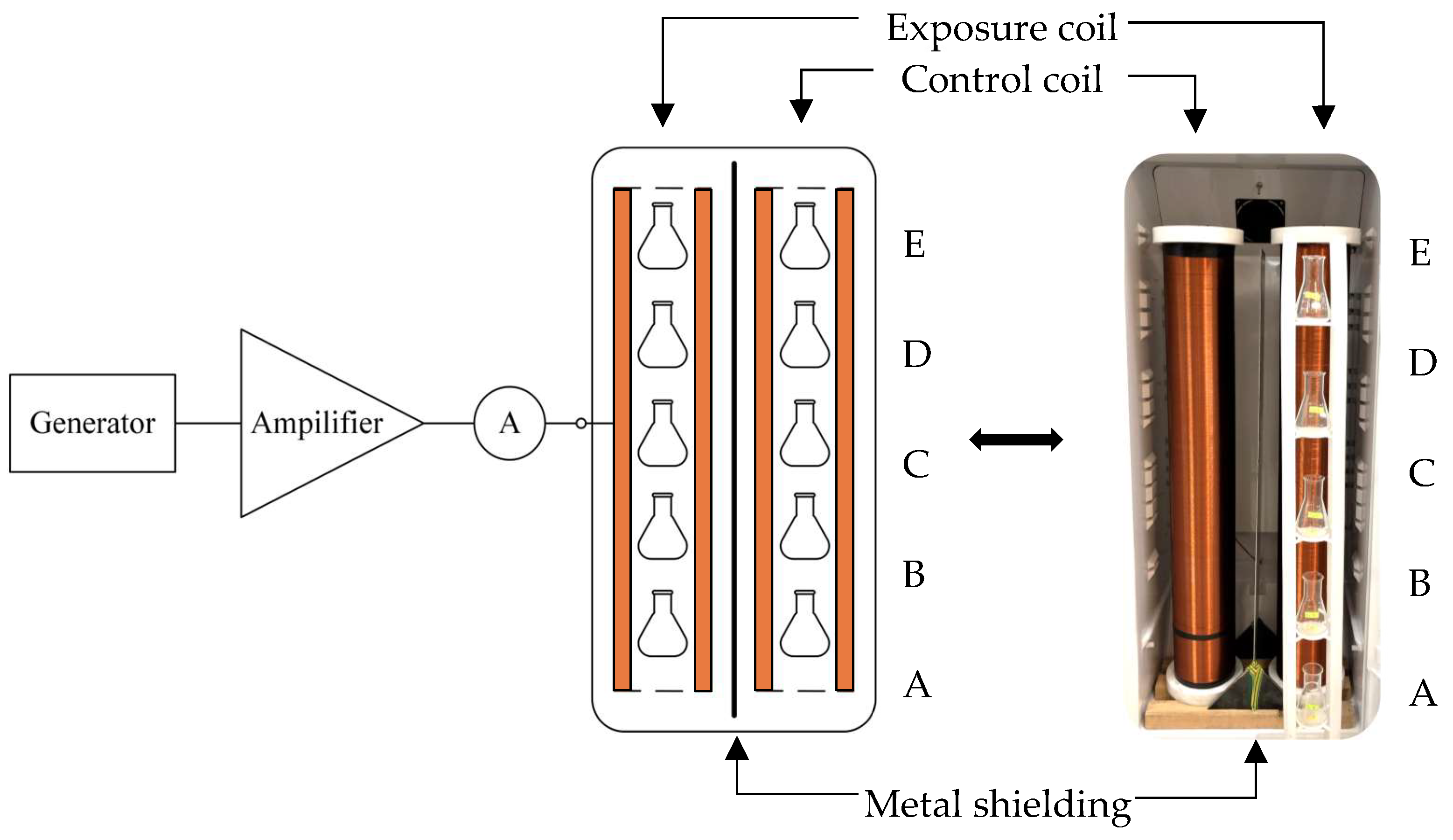
Figure 1. Block diagram of the exposure configuration. Letters A–E represents respective position of the sample.
Applsci 14 09409 g001
Figure 2. Vectors of the static magnetic flux density at individual positions of the exposure coil in the complete exposure configuration in 3D space. Each vector is a graphical representation in 3D space of values from the two last columns (BDC and α) of Table 3. The values of BX, BY and BZ are Cartesian components of the respective BDC in exact position, resulting in the values of BDC and α as presented in Table 3.
Applsci 14 09409 g002
Figure 3. Vector of the static magnetic flux density at position C of the exposure coil corresponding to five times the geomagnetic field.
Applsci 14 09409 g003
Figure 4. Temperature difference at position C of the exposure and control coil during 7-h EMF exposure with diverse settings.
Applsci 14 09409 g004
Figure 5. (A) Biological system responses after 7 h of EMF exposure with nonspecific ELF EMF exposure–1st set of experiments. (B) Corresponding scatterplot of E and C distribution during the whole set of 10 experiments.
Applsci 14 09409 g005aApplsci 14 09409 g005b
Figure 6. (A) Biological system responses after 7 h of EMF exposure with artificial settings of IPR conditions–2nd set of experiments. (B) Corresponding scatterplot of E and C distribution during the whole set of 10 experiments.
Applsci 14 09409 g006
Figure 7. The frequency histogram of samples after 7-h ELF EMF exposure with nonspecific conditions (left) and with artificial settings (right) of IPR conditions. Frequency of occurrence of specific value of partial growth coefficient for the exposed (E) and control (C) sample within the whole dataset.
Applsci 14 09409 g007
Figure 8. The box diagram of samples after 7-h EMF exposure with nonspecific (left) and with artificial settings (right) of IPR conditions—representation of the datasets behind the histograms from previous figure. The borders of horizontal lines indicate minimal and maximal values; the central line indicates median within interquartile range.
Applsci 14 09409 g008
Figure 9. Scatterplots of relation between E and C, for (A) nonspecific exposure conditions over all positions of samples during the whole set of 10 experiments for both experimental data sets; (B) artificial exposure conditions over all positions of samples during the whole set of 10 experiments for both experimental data sets.
Applsci 14 09409 g009aApplsci 14 09409 g009b
Figure 10. A diagram illustrating how an ELF can influence cells through IPR theory.
Applsci 14 09409 g010
Table 1. Exposure levels of magnetic field for each experimental set.
Induction of DC MF
BDC (µT)
Induction of AC MF
BAC (µT)
CECE
First experiment
(Exposure settings with nonspecific conditions)
3939No AC field70.2 (50 Hz)
Second experiment
(Artificial settings of IPR conditions)
50.92254.6No AC field458.28 µT
Table 2. Resonance frequencies of individual ions calculated for the GMF value of 39 µT- Magnesium ion highlighted as most suitable target for the application of EMF at 50 Hz.
Targeted IonCharge to Mass Ratio
q m (C/kg)
Frequency of Time-Varying Magnetic Field f C (Hz)
Calcium Ca2+ 2 × 2.4074 × 10 6 29.8862
Hydronium H+ 9.5723 × 10 7 594.1544
Sodium Na+ 4.1969 × 10 6 26.0502
Potassium K+ 2.4678 × 10 6 15.3175
Chlorine Cl 2.7215 × 10 6 16.8925
Magnesium Mg2+2 × 3.9698 × 10649.2811
Zinc Zn2+ 2 × 1.4758 × 10 6 18.3202
Nitrogen N−5 5 × 6.8886 × 10 6 213.7865
Iron Fe−3 3 × 1.7277 × 10 6 32.1724
Phosphorus P3+ 3 × 2.0400 × 10 6 38.6707
Table 3. Magnetic flux density of static field at individual positions of the exposure coil.
PositionBX (µT)BY (µT)BZ (µT)BDC (µT)α (°)
E24.111.8−20.834127.7
D45.511.61.64788.1
C40.49.7817.34567.4
B41.419.914.948.372
A502122.358.667.6
Table 4. Resonance frequencies of individual ions calculated for the geomagnetic field value of 50.92 µT. Potassium ion highlighted as a target for the application of EMF corresponding to the magnitude 5 times BDC (50 Hz considered as 2nd subharmonic frequency).
Targeted IonCharge to Mass Ratio
q m (C/kg)
Frequency of Time-Varying Magnetic Field f C (Hz)
Calcium Ca2+ 2 × 2.4074 × 10 6 39.0206
Hydrogen H+ 9.5723 × 10 7 775.7524
Sodium Na+ 4.1969 × 10 6 34.0122
Potassium K+2.4678 × 10619.9992 ~ 20
Chlorine Cl 2.7215 × 10 6 22.0555
Magnesium Mg2+ 2 × 3.9698 × 10 6 64.3434
Zinc Zn2+ 2 × 1.4758 × 10 6 23.9197
Nitrogen N−5 5 × 6.8886 × 10 6 279.1284
Iron Fe−3 3 × 1.7277 × 10 6 42.0056
Phosphorus P3+ 3 × 2.0400 × 10 6 50.4900
Table 5. Basic statistical data after 7-h ELF MF exposure. The data comprised the following: respective partial growth coefficient (E and C); corresponding set of 5 samples for exposed and 5 for control group at each position (A–E) within the incubator, totaling 50 samples for the whole set of 10 experiments; average value of all partial growth coefficients for respective positions; standard deviation and standard error computed for all 50 data samples; minimal and maximal value of each data set.
SampleCountAverageStandard DeviationStandard ErrorMinimumMaximumEffect Size
Exposure with nonspecific conditionsCohen’s dGlass’s delta
E 509.70244.53840.64184.0222.490.4566260.536129
C 507.86683.42380.48423.816.54
Exposure with artificial settings of IPR conditions
E 509.10463.58150.50652.517.980.5256880.616607
C 507.4362.70610.38271.9613.41
Table 6. Independent two-sample two-tailed Student’s t-test. The t-statistic measures how far apart the group means are in terms of standard errors. The larger the t-value, the more likely it is that the difference in means is statistically significant. Similarly, if the p-value is less than the significance level (in this case, 0.05), the null hypothesis is rejected, suggesting that there is a statistically significant difference between the group means.
t-Statistic (t Value)p-Value
Exposure with nonspecific conditions
2.23390.0278
Exposure with artificial settings of IPR conditions
2.62850.0100
Disclaimer/Publisher’s Note: The statements, opinions and data contained in all publications are solely those of the individual author(s) and contributor(s) and not of MDPI and/or the editor(s). MDPI and/or the editor(s) disclaim responsibility for any injury to people or property resulting from any ideas, methods, instructions or products referred to in the content.