1. Introduction
A cone crusher is one of the most widely used crushing equipment in crushing operations. In the crushing chamber, the granular material can be crushed into small particles because of the eccentric motion of the mantle. The structure of a traditional cone crusher is shown in
Figure 1a.
The working mode is that the main shaft 1 drives the eccentric sleeve 2, which drives the mantle 3 to realize eccentric rotation, so as to realize the function of squeezing and crushing the granular materials in the crushing chamber. The advantages include high crushing efficiency, large crushing ratio, and uniform particle size of crushing products. However, it also has the disadvantages of complex structure, high energy consumption, and large wear and tear.
The advantages of a 6-DOF robotic crusher include high flexibility, simple structure, convenient maintenance, and the ability to realize intellectualization, which is similar to a parallel robot. In order to achieve the best crushing effect, that is, to achieve the goal of energy saving, consumption reduction, and efficiency increase, it is necessary to formulate corresponding crushing strategies for the 6-DOF robotic crusher according to specific materials and crushing chamber. It can provide a reference for the research of optimal control. Previous researchers on the optimization of cone crushers focused on the crushing chamber [
1,
2,
3,
4] liner material and wear [
5,
6,
7].
The research on the control objectives of cone crushers focused on feeding [
8], hopper liquid level [
9], and screening [
10]. The control methods include the adaptive time-varying state method [
8], fuzzy PID method [
11], brain emotion learning (BEL) [
12] method, etc. Different from the traditional cone crusher, the control and optimization of the 6-DOF platform and crusher need to be considered at the same time. The previous research on the 6-DOF platform focuses on posture. In terms of optimization and control, Zhong [
13] has proposed a 6-DOF target attitude tracking method, which is robust to severe occlusion. Lin [
14] has proposed a multi-stage simplified modeling method for establishing the kinematic static model of a flexible platform with complex configuration. The motion dynamics of the 6-DOF flexible platform have been analyzed, which provides a basis for the design and optimization of flexible mechanisms based on bridge amplifiers. Zhang [
15] has proposed an improved method for the mechanical manual mechanical model of a 6-DOF robot to improve its motion accuracy. As for the optimal control of the 6-DOF robotic crusher, it is necessary to combine the above research results and take the research content of this paper as the reference of optimal control to achieve the goal of energy conservation, consumption reduction, and efficiency increase. In terms of the specific control method of the 6-DOF robotic crusher, Li [
16,
17] has considered its no-load and full-load conditions, established the corresponding kinematics and dynamics equations, and analyzed and optimized its workspace and singularity. Wang [
18] has analyzed the kinematics of the 6-DOF robotic crusher, established the traditional PID and fuzzy PID control models, and simulated them. Zhang [
19] analyzed the working structure and control strategy of the 6-DOF robotic crusher, established the SimMachanics model of the crusher, and simulated the displacement control of the driving cylinder.
As for the optimization algorithm, with the expansion of the application scope of optimization and the deepening of optimization research, the optimization algorithm has been widely researched and applied in many fields. Among them, the swarm intelligence optimization algorithm has attracted much attention because of its obvious advantages. The swarm intelligence optimization algorithm can take advantage of the advantages of groups, and provide a basis for finding solutions to complex distributed problems without centralized control and a global model. In recent years, the research direction has focused on multi-objective ant colony optimization [
20], artificial bee colony algorithm [
21], cat colony algorithm [
22], and other swarm algorithms.
In previous research [
23,
24], the impact of specific material and operating parameters on the crushing products, crusher energy consumption, and liner wear. In order to achieve optimal crushing, the 6-DOF crusher can theoretically adjust its working parameters freely. Therefore, it is necessary to expand the research on the results of previous research [
23,
24], study the performance of the crusher under different working conditions, and based on this, carry out optimization calculations to provide reference for real-time adjustment of the 6-DOF crusher. In this paper, the quality fraction of crushed products below 12 mm, total energy consumption, wear amount, energy efficiency, and output are taken as the performance indicators of the six degrees of freedom crusher. The cavity shape of the PYGB1821 cone crusher is taken as the research object, and the suspension point position, precession angle, and speed are variables under different working conditions. Combined with experimental data on feed particle size, the performance indicators of the 6-DOF crusher are researched under different working conditions. And the weight determination method of fuzzy multi-attribute decision-making problem is used to determine the weight of each crushing cavity depth wear.
Furthermore, an optimization function was established. This function takes the above performance indicators as the optimization objectives, and the takes the above working conditions as the optimization variables. The weight determination method of fuzzy multi-attribute decision-making problem is used to determine the weights of different crushing chamber heights and optimization objective functions. Based on the experimental data of AnSteel Group, combined with the weight determination method of the fuzzy multi-attribute decision-making problem, the gray wolf optimization algorithm is used to solve the problem, and the optimization results of different crushing strategies and preferences are obtained. The model is universal, and the result can be used as an adaptive adjustment strategy for a 6-DOF robotic crusher. It can also provide a reference for the design of a cone crusher with a traditional structure.
2. Performance Indexes and Working Conditions of 6-DOF Robotic Crusher
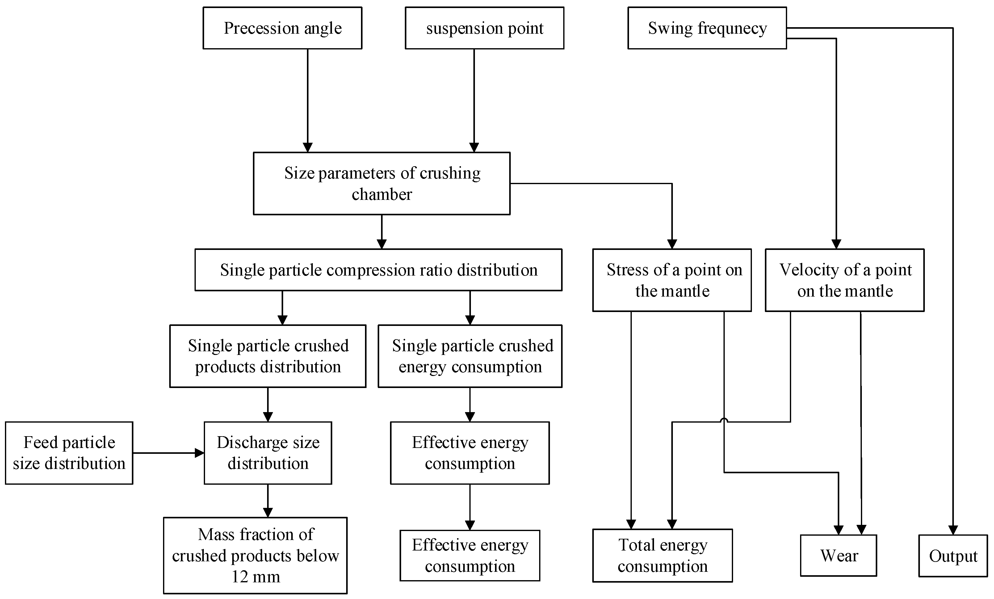
The performance index of the crusher shall reflect the performance of the crusher, such as energy consumption, liner wear, crushing efficiency, particle size of crushing products, etc. The motion mode of the mantle of the 6-DOF crusher is similar to that of the traditional cone crusher, which is determined by the precession angle φP, suspension point O′, and swing frequency f. When the crushing chamber shape is constant, the performance index is determined by the above three parameters.
Therefore, they are used as the working condition of the crusher. Combined with the author’s previous research results [
23,
24]. The performance index calculation process is shown in
Figure 2:
Therefore, the performance index of the crusher under certain crushing chambers and working conditions can be obtained. Because the wear of the liner is related to the height of the crushing chamber, it is inconvenient to use this working index as an optimization variable. Equivalent wear calculation is required.
3. Equivalent Wear Calculation
After introducing normalized weight coefficients for the wear amount at each height of the crushing chamber, and integrating the wear amount at each height of the crushing chamber for calculation, Equivalent wear can be defined as follows:
where
wz(
z) is weight function,
.
The method of determining the weight coefficient in multi-objective optimization is used to determine the weight function. The weight function determines the method of determining the weight coefficient in multi-objective optimization. When the multi-objective optimization problem includes
k objective functions, the objective function can be expressed as
where
wi is weight coefficient,
fi(
x) is the optimization objective function.
When function (2) is used to calculate the equivalent wear amount of the crushing chamber, the wear amount and weight coefficient of each crushing layer can be used for calculation.
Theoretically, weights have infinite solutions. The importance of different heights in the crushing cavity is different, and the closer to the gape, the more important the wear index is. It is difficult to determine the weight directly. In this paper, the weight determination method of fuzzy multiple attributes decision making (FMADM) is used to determine the weight of different crushing chamber heights.
Define as interval fuzzy set of scheme x. Where are the membership upper bound, membership lower bound, non-membership upper bound, and non-membership lower bound of scheme x, respectively. Define the hesitation upper bound and hesitation lower bound as , . For example, for a certain scheme , it can be understood that 1–2 of 10 people support the scheme, 5–6 people oppose it, and 2–4 people hesitate.
Interval intuitionistic fuzzy numbers are used to express the membership and non-membership functions of the scheme. The interval fuzzy numbers corresponding to very high (VH), high (H), formal (F), low (L), and very low (VL) in the fuzzy evaluation semantics are shown in
Table 1:
When there are
K decision makers,
J indicators, and
I schemes,
I ×
J ×
K tensor can be established as an element in the tensor. The decision matrix for a decision maker can be expressed as follows:
Formula (3) can be expressed by interval fuzzy set:
3.1. Weighted Average Operator IIFWA
The weighted average operator and Euclidean distance need to be introduced when calculating the weight of decision makers. The algorithm is as follows:
If
is a group of interval intuitionistic fuzzy numbers, its weighted average operator
IIFWA is [
25]
3.2. Euclidean Distance
If
A and
B are two interval intuitionistic fuzzy sets, the Euclidean distance of the two schemes is defined as [
26]
For t interval intuitionistic fuzzy numbers, the objective function of decision-maker weight optimization is
where
is the comprehensive decision matrix,
.
After solving the optimization function in Formula (8), the wear weight of each crushing layer in the crushing chamber can be obtained.
The wear of each crushing layer can be regarded as a decision maker. In the feasible solutions under different precession angles, suspension point positions, and swing frequencies, the corresponding wear of each crushing layer can be regarded as the evaluation semantics in different schemes. The smaller the wear, the better the scheme. The relationship between evaluation semantics and wear is defined in
Table 2.
Table 2.
Relationship between wear and evaluation semantics.
Table 2.
Relationship between wear and evaluation semantics.
| Wear | [0, Bou1] | (Bou1, Bou2] | (Bou2, Bou3] | (Bou3, Bou4] | (Bou4, +∞) |
|---|
| Language variables | VH | H | F | L | VL |
The weight coefficient of each crushing layer and the equivalent wear can be obtained by solving Formula (8).
4. Multi-Objective Optimization Function
The purpose of optimization is minimizing total energy consumption
Wsum, wear Δ
he, and maximizing mass fraction of crushed products below 12 mm
M12, energy consumption efficiency
ηW the output
Vsum by adjusting the precession angle
φP, the position of the suspension point
O′, and the swing frequency
f of the mantle to realize the optimization of the above objectives. The optimization objective function can be established as follows:
In the above formula, there is a large difference in the order of magnitude of each optimization objective function, so dimensionless calculation of each objective function is required. Taking a specific working condition as the reference condition, let , , , , . Where Wsum,basic, M12,basic, ηW,basic, Vobj,basic, Δhe,basic is the performance index under this condition.
The optimization objective function is transformed into
The optimal working conditions and performance indexes of the crusher can be obtained by solving Formula (9).
5. Numerical Example
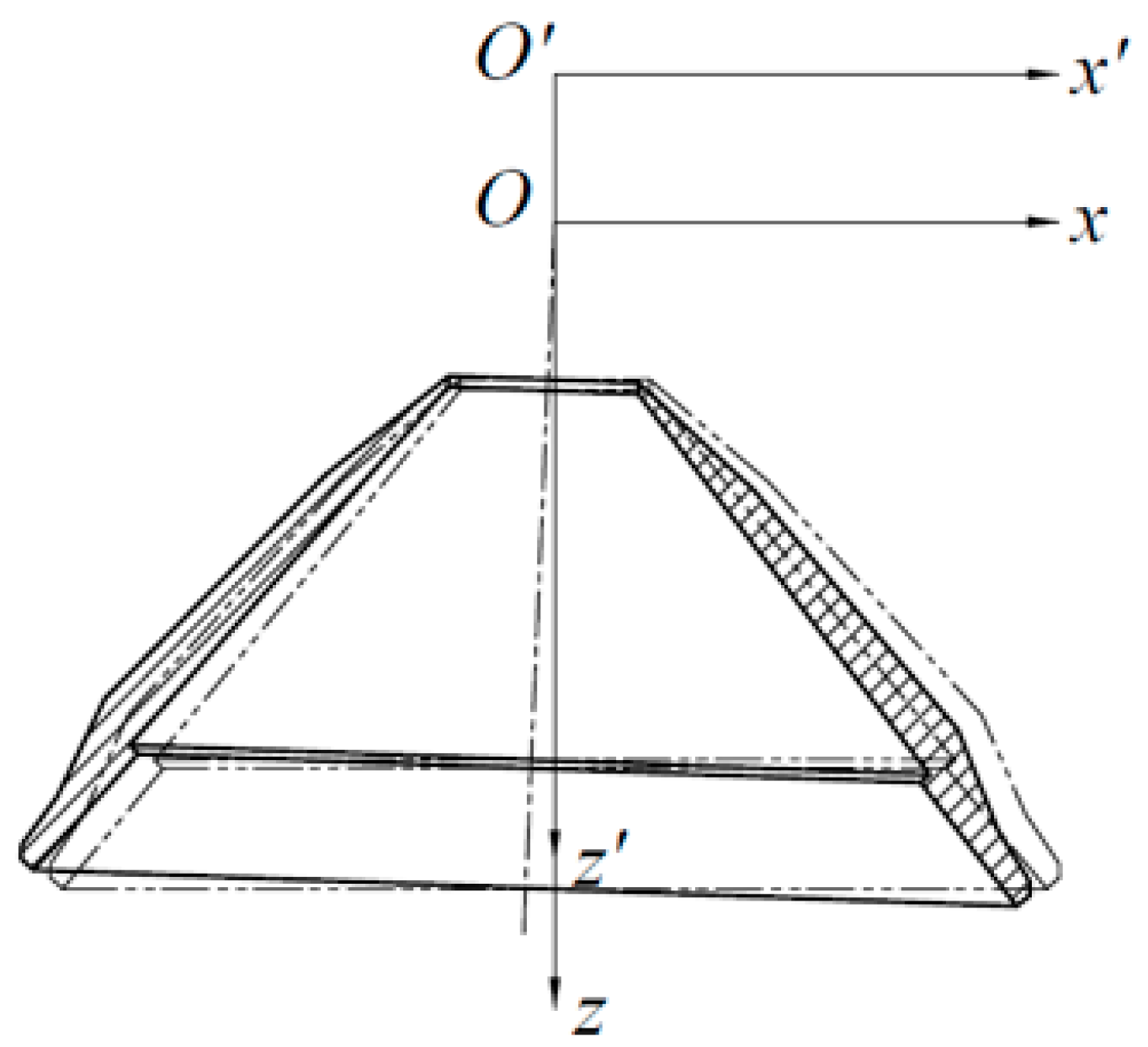
Taking the PYGB1821 cone crusher as an example, the crushing chamber and suspension point position are researched. Taking the mantle coordinate system of the PYGB1821 cone crusher as the reference coordinate system, the position of the suspension point is defined as the z coordinate of the suspension point of the transformed coordinate system in the reference coordinate system, which is recorded as
O′, as shown in
Figure 3.
The reference working conditions in
Section 4 are defined as
O′ = 0 mm,
φP = 2.5°,
f = 5 Hz. The performance index under the basic condition is determined by DEM simulation and experiment. For details of the modeling of the mass fraction of crushed products below 12 mm and wear, see [
24], and for details of the modeling of the energy consumption and energy consumption efficiency, see [
23]. Under reference conditions, energy consumption is
Wsum,basic = 131.1 kW·h,
M12,basic = 0.6285,
ηW,basic = 0.2248,
Vobj,basic = 415 t, according to the weight obtained by method 1 in 5.1, the hourly equivalent wear is Δ
he,basic,1 = 0.4987, and the equivalent wear calculated according to the weight obtained in methods 2 and 3 is Δ
he,basic,2 = 0.3942.
5.1. Equivalent Wear Calculation
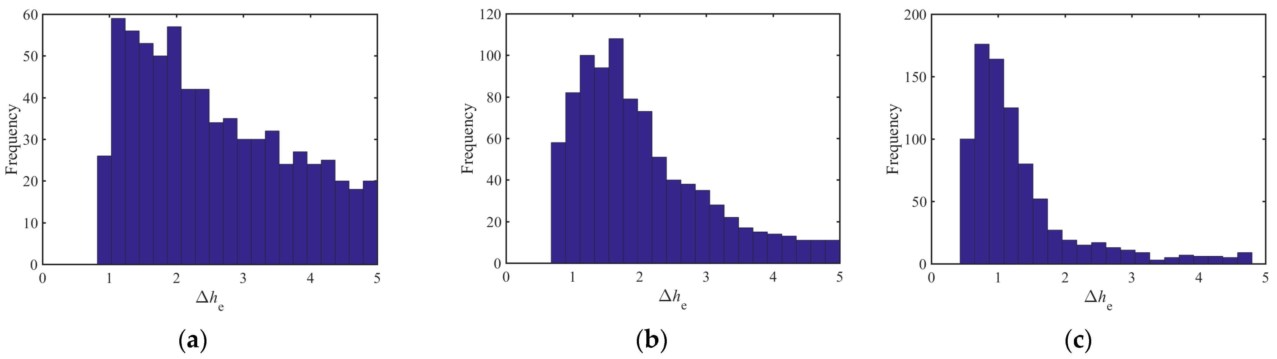
According to previous research, when the swing frequency is 4 ≤ f ≤ 5.57, the crushing chamber is divided into 10 crushing layers. Under the reference conditions, the hourly wear of each crushing layer is 0.0505, 0.0797, 0.1233, 0.1578, 0.1974, 0.2642, 0.2412, 0.2367, 0.2390 and 0.2472 mm, respectively. The wear of each crushing layer under different conditions is defined as the relative wear compared with the wear amount under reference conditions.
Taking the second, fifth, and ninth crushing layers as an example, the specific wear frequency histogram of all feasible solutions is shown in
Figure 4:
The variation range of the relative wear of each crushing layer is different, and the difference between the maximum value and the minimum value is large, and it presents the characteristics of the long-tail distribution. The satisfaction boundary of each crushing layer needs to be determined separately. Among all feasible schemes, the minimum specific wear of the broken layer is the most satisfactory wear Δ
he,min. The satisfaction boundaries calculated by exponential interpolation are
,
,
,
, respectively. The satisfaction boundary of each crushing layer is shown in
Table 3:
The range of wear from the upper part to the lower part of the crushing chamber gradually increases. Therefore, the boundary gap of satisfaction also increases. When choosing different satisfaction schemes for each decision maker, the weight results calculated are different. Since the theory within the feasible region can select an infinite number of schemes, it is necessary to select the scheme by sampling. The scheme selection is as follows:
Select the most satisfactory scheme of each decision maker (each crushing layer), respectively;
Select the scheme that is less than and closest to Bou1 among all decision makers;
Select the scheme that is less than and closest to Bou2 among all decision makers.
Taking method 1 as an example, after removing the duplicate scheme, the selected scheme is shown in
Table 4:
According to Formula (8), the objective function of wear weight optimization is
The scheme selected according to the above three methods is substituted into Equation (10), and the weight of each crushing layer is calculated by a genetic optimization algorithm, and the result is the following in
Table 5:
The wear weight results obtained according to the satisfaction of decision makers in method 1 focus on the wear in the parallel area, and the wear weight results obtained according to methods 2 and 3 do not particularly focus on a certain crushing chamber area. Combined Formula (2), the equivalent wear of the mantle liner, can obtained.
5.2. Optimization Objective Function
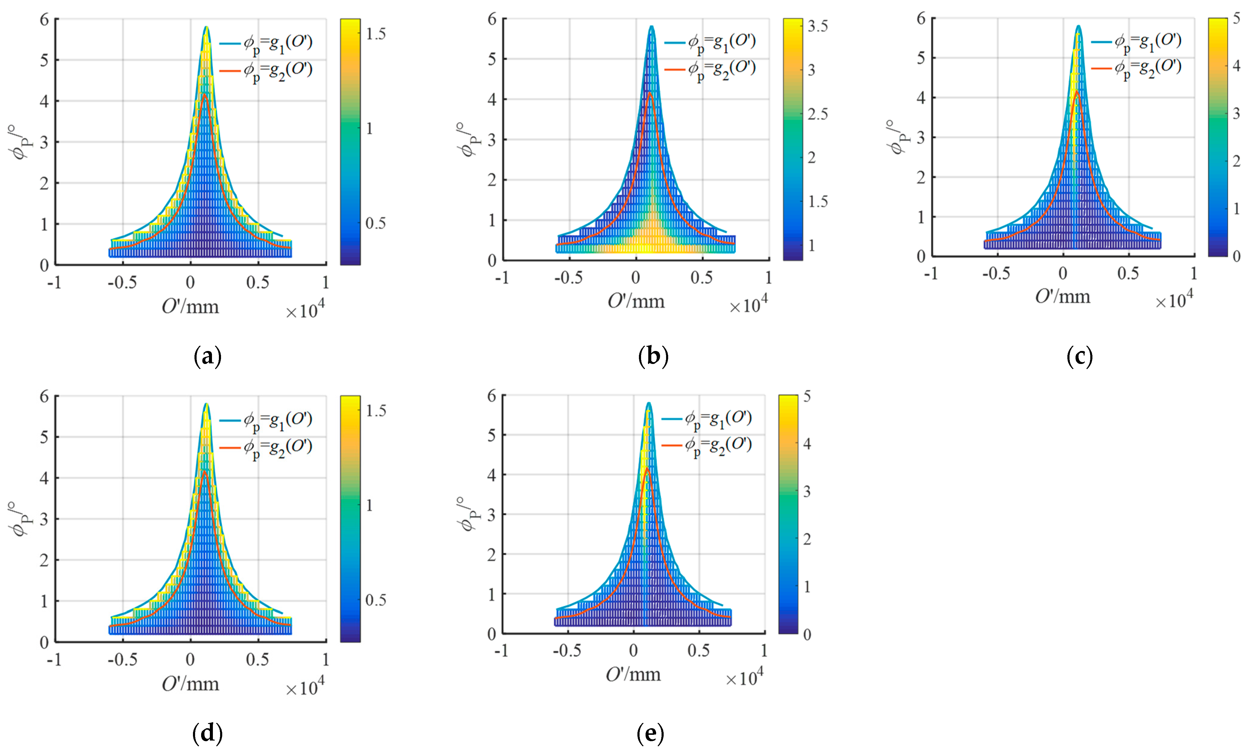
According to the optimization objective functions in the process calculation Formula (9) in
Figure 3, taking the swing frequency
f = 5 Hz as an example, the optimization objective values under different working conditions are shown in
Figure 5:
The envelope shown in this figure is a constraint function φP = g1(O′). When φP ≥ g1(O′), the theoretical compression ratio of a certain crushing chamber depth ηt ≥ 1, is not in line with the actual situation, so the constraint is φP ≥ g1(O′). The actual production conditions require M12 ≥ 50%, and the curve shown in this figure is a constraint function φP≥g2(O′). When φP ≥ g2(O′), M12 ≥ 50%. So, the constraint is φP ≥ g2(O′). When the suspension point position O′ < −4200 mm or O′ > 6000 mm, the maximum value of the precession angle does not change significantly when the suspension point position O′ changes, and it is of little significance to change the suspension point position at this time. Therefore, the position constraint of the suspension point is set to −4200 mm ≤ O′ ≤ 6000 mm.
According to previous research [
23], the output
Vsum can be expressed as a function of the swing frequency
f of the mantle. After linear interpolation:
The
Vobj,basic = 415 t, according to
Section 4, the output optimization objective function
Vobj can be expressed as
When solving the multi-objective optimization of the optimization objective function in Formula (10), there are infinite solutions in theory. It is necessary to convert the weighted method into single objective optimization and use the weighted method of fuzzy multi-attribute decision-making problem in
Section 3 to determine the weight of each optimization objective.
Taking wear weight method 1 as an example, the boundary value of satisfaction of each optimization objective is shown in
Table 6:
The feasible solution is selected as follows:
- (1)
Select the optimal scheme of each decision maker (optimization objective);
- (2)
Select the scheme that is less than and closest to Bou1 among all decision makers;
- (3)
Select the scheme that is less than and closest to Bou2 among all decision makers.
Taking method 1 as an example, the satisfaction of decision makers is shown in
Table 7 after removing duplicate schemes:
The linear constraint is set as the sum of the maximum target weight and the minimum target weight is 0.5; that is,
λ1 +
λ2 +
λ5 = 0.5,
λ3 +
λ4 = 0.5. Optimization objective weight optimization function can be converted into
The weight of each optimization objective calculated by the genetic optimization algorithm is shown in
Table 8:
Thus, the optimization function can be expressed as
The gray wolf optimization algorithm is used to optimize the above optimization functions, and the values of relevant parameter settings are as follows. The number of agents
SearchAgents_no (number of wolves): 15; maximum iterations
Max_iter: 200; lower bound of variable value
lb: [0.2, −4200, 4.33]; upper bound of variable value
ub: [6, 6000, 5.67]. The optimization calculation results are shown in
Table 9:
In the optimization results, when the wear weight is different but the optimization target weight is the same, the optimization results are close. The suspension point position O′ of the optimization scheme is between –2400 mm and –2923 mm. The precession angle φP is 0.66~0.76 of the maximum precession angle corresponding to the suspension point position of each optimization scheme. The optimization result of swing frequency is at or near the extreme point of the value range.
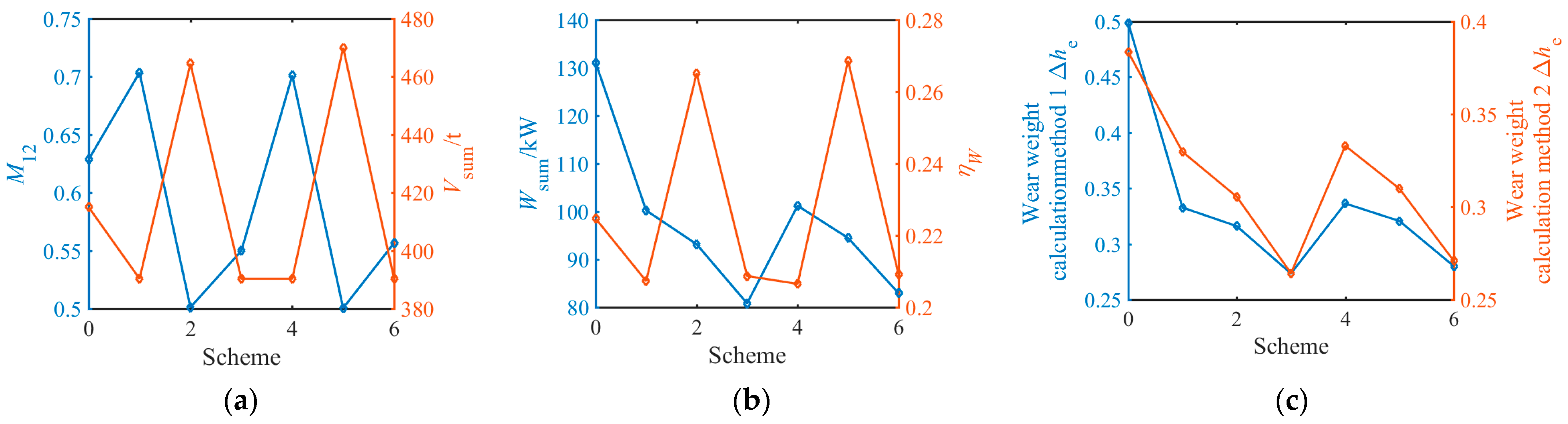
The performance indicators of each optimization scheme are shown in
Figure 6:
The non-optimized scheme is recorded as Scheme 0, and Schemes 1–6 are the schemes in
Table 9. Among the optimized performance indicators, the mass fraction of particles below 12 mm is 79.6–112% of the original scheme, and the maximum energy consumption of the same output is 63.49–82.08% of the original scheme. According to the wear weight method 1, the equivalent wear of the same output is 56.61~71.72% of the original scheme. According to the wear weight method 2, the equivalent wear of the same output is 71.18~91.42% of the original scheme.
The wear of different crushing chamber depths hourly of each optimization scheme is shown in
Figure 7:
In all optimization schemes, the compression ratio of the upper part of the crushing chamber is increased, the wear of the upper part of the crushing chamber is slightly increased compared with the original scheme, and the wear of the parallel area is significantly reduced. When the equivalent wear is calculated according to the wear weight method 1, the equivalent wear of each optimization scheme Δhe,1 is 54.82–67.45% of the original scheme, respectively. When the equivalent wear is calculated according to wear weight methods 2 and 3, the equivalent wear Δhe,2 of each optimization scheme are 68.90–86.83% of the original scheme, respectively. When considering the output, each optimization scheme Δhe,1/Vsum is 56.61–71.72% of the original scheme, respectively, and Δhe,2/Vsum is 71.18–92.32% of the original scheme, respectively.
6. Discussion
Up to now, several relevant studies [
27,
28,
29] have shown the necessity of designing crushing equipment. The aim of this study was to determine the optimal control strategy for a 6-DOF crusher based on its crushing behavior. The research method is to establish an optimization function for the working conditions and performance indicators of the crusher and solve it using the gray wolf optimization algorithm. The research conclusion shows that using optimized crushing methods can effectively improve crushing efficiency and reduce liner wear. Based on the research content of this article, more in-depth research can be conducted from the following aspects in further research: The working conditions obtained from the optimization results in this article can be combined with the 6-DOF platform control method. Considering the kinematic and dynamic models of the mantle and actuator, a 6-DOF crusher dynamic kinematic control and adjustment method based on optimization crushing is obtained.
7. Conclusions
In this paper, the optimization method of the 6-DOF robotic crusher is researched. The main research results include the following:
Based on the previous research results, the influence of the working parameters of the 6-DOF robotic crusher on the performance index has been researched. Combined with the fuzzy multi-attribute weight method, the equivalent wear model has been established.
The optimal design control model of the 6-DOF robotic crusher has been established. The optimization objective function is established based on the performance index of the 6-DOF robotic crusher, and the working parameters are taken as the optimization variables. The weight of each optimization objective has been obtained by fuzzy multiple attributes decision making.
The above model is verified by taking the non-worn crushing chamber of the PYGB1821 cone crusher as an example. When calculating the equivalent wear, two wear weighting methods have been obtained. One method focuses on the wear in the parallel zone, and the other method regards the importance of the wear of each crushing chamber height as the same. The optimization objective weight is obtained by the fuzzy multi-attribute weight method. The gray wolf optimization algorithm is used to solve the above optimization model. In the optimized scheme, the actual compression of the upper part of the crushing chamber is increased compared with the original scheme. It is helpful to break large particles as soon as possible, so as to reduce the expectation of particle size in the parallel zone and in order to save energy and reduce consumption on the premise of maintaining output and particle size. When the equivalent wear weight method is different and the optimization function weight method is the same, the different optimization schemes have the same emphasis and the optimization results are similar.


