1. Introduction
Polarization is a characteristic of transverse waves (waves that oscillate perpendicular to their travelling direction). Light as an electromagnetic wave is formed by electric
and magnetic
vibrations, which are perpendicular to each other, with its direction of propagation perpendicular to both [
1]. If those vibrations occur in more than one plane, it is known as unpolarized light. However, it will be polarized if the vibrations occur in every moment at a single plane. The process of transforming unpolarized light into polarized light is known as polarization (modifying the orientation of its electric field) [
2].
An electromagnetic wave travels in vacuum at the speed of light
, slowing down if it travels through matter. The relationship between the speed of light in vacuum and through a material
is defined by its refractive index,
[
3]. So, if the speed of a light ray is greater in medium 1 with index
than in medium 2 with index
(
), the ray will move closer to the perpendicular with respect to the surface. Likewise, the ray will move away from the perpendicular if it speeds up.
Unpolarized light can be polarized using different methods, such as selective absorption or dichroism (some crystalline materials absorb more light in one plane than another, so that while propagating, it becomes more polarized), scattering (dispersion polarization occurs when an electromagnetic wave hits a molecule of a substance, is absorbed and re-emitted; this wave will be reemitted in the plane perpendicular to the oscillation), reflection (when light is incident on a surface at a certain angle, it is possible for the reflected light to become partially or completely polarized) and birefringence (a beam of light passes through some crystals separately in two rays, which travel at different speeds and at the same time are polarized perpendicularly) [
4].
Considering polarization by reflection, the degree of the generated linear polarization depends on the angle that the ray of light makes with the normal to the surface. The angle in which the reflected light is fully polarized is known as Brewster’s angle [
5]. Typically, this angle is estimated in physics or optics laboratories by shining a laser beam (with linear polarization perpendicular to the plane of incidence) onto a semi-transparent surface. At a certain angle of incidence, the reflected beam will have almost zero intensity, corresponding to the Brewster’s angle [
6]. The mechanical process is generally carried out manually or by rotating a motor, while the intensity of the reflected beam is measured by eye or using a power meter [
7,
8,
9,
10] (this means that the sensor must be placed perpendicular to the beam for each measurement, sometimes complicating the mechanical mount).
This proposal is based on the automatic measurement of Brewster’s angle using Lego Mindstorms [
11] Ev3 components (aiming to demonstrate that Mindstorms models can be used for general electronic control purposes in different projects and approaches) and a micro:bit board as control elements. A machine vision sensor (Huskylens camera and an easy-to-use artificial intelligence AI device equipped with multiple functions, such as image recognition, object tracking, object recognition, line tracking, color recognition and tag recognition) will be used to detect the decrease in and extinction of the reflected beam intensity, making use of its feature to recognize colors and to store the detection in a variable for a post-processing stage. Once the intensity of the beam is the minimum, the motor responsible for rotating the material under test will stop, storing the angle at which this occurred. Finally, this angle will be used to estimate the refractive index of the material.
The primary purpose of this research is to develop an innovative and automated tool that estimates Brewster’s angle and the refractive index of semitransparent material, aiming to enhance the teaching/learning experience in undergraduate and graduate physics and engineering courses by providing a hands-on, interactive method for understanding and measuring these optical phenomena.
This research introduces a novel application of LEGO Ev3 components and a machine vision camera in the automated measurement of Brewster’s angle and the refractive index of materials. The integration of these technologies demonstrates the potential of using these devices to make scientific devices, which has not been extensively explored in the literature. The developed tool offers significant practical value by providing an engaging and interactive method for students to learn about optical phenomena. It bridges multiple areas of knowledge, including electronics, programming, physics, design, and mathematics, making it a versatile educational resource. Additionally, the tool’s potential for remote laboratory implementation enhances its applicability in diverse educational settings, particularly in distance learning environments.
It is worth emphasizing that the proposed implementation does not intend to replace the construction and use of traditional experimental arrangements and the pedagogical benefits that they entail. However, it is a fact that students have different interests and abilities, so certain classic methods used in the teaching/learning process may be tedious and unattractive for some.
Based on the above-described information and considering that the present proposal presents an innovative application of AI and automation in the field of optical measurements, a brief theoretical description of the concepts used, the experimental implementation of the proposal, the corresponding experimental results and the conclusions will be the content of this article.
2. General Concepts
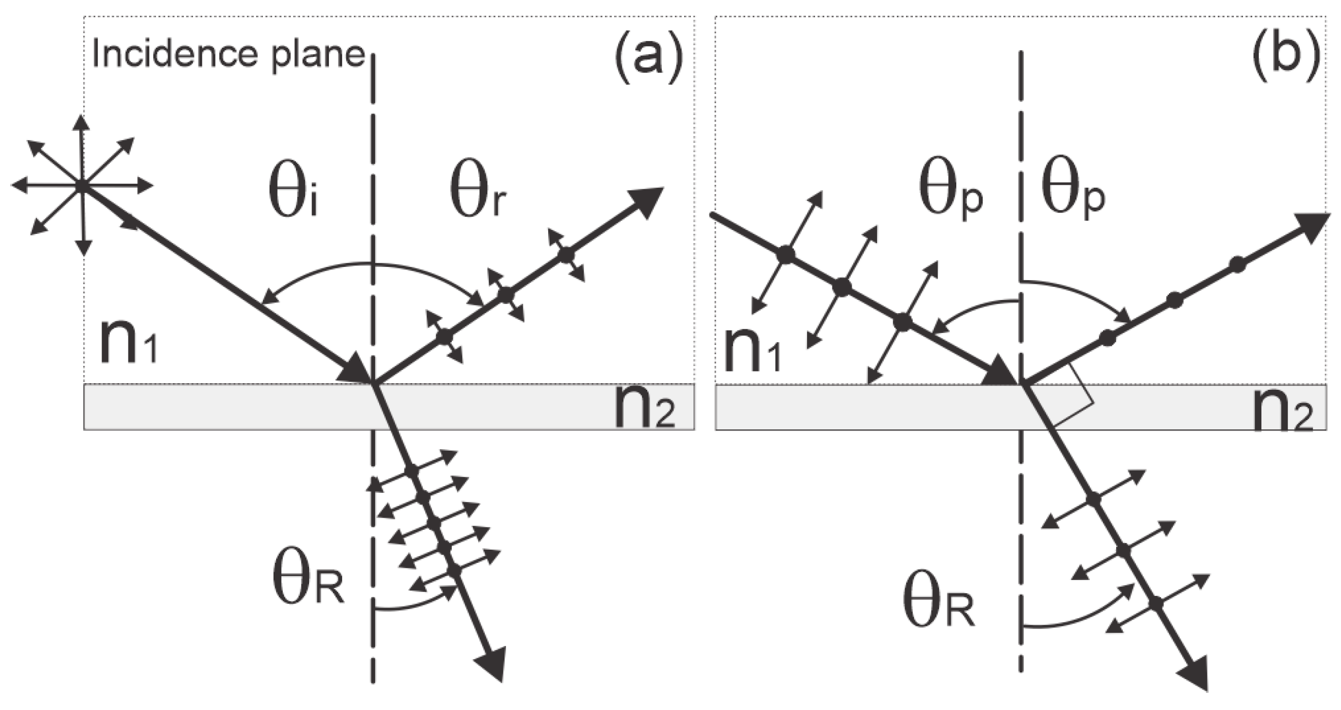
As mentioned in the previous section, unpolarized light can be partial or fully polarized by means of reflection. In
Figure 1a, unpolarized light is incident on a transparent surface. The reflected beam will be partially polarized (mostly horizontally polarized) for most angles of incidence when the electric field vector is perpendicular to the incidence plane (represented by “dots” in the figure)—that is, parallel to the surface.
For a specific incidence angle, called the polarization angle
(the reflected and transmitted rays are perpendicular to each other), the reflected light will be fully polarized in a perpendicular direction with respect to the plane of incidence, as shown in
Figure 1b. The transmitted or refracted light is partially polarized in a direction parallel to the plane of incidence.
Using the law of reflection and Snell’s law, that is
and considering an angle where the reflected angle is completely polarized with its electric field parallel to the surface (the partially polarized refracted beam)—for which
and
will be renamed as
, forming 90° between the reflected and transmitted beam—the following expressions are obtained:
By using the identity
, then
From Equation (5), the expression for
[
12] is
It is known and it can be observed that, by using Equation (5), the refractive index of a material
can be calculated if Brewster’s angle and
are known. At this angle, the intensity of the refracted light is minimum since only s-polarized light (perpendicular to the plane of incidence) is reflected, generally monitored by eye or a light power meter in a laboratory experiment.
Figure 2 depicts the general schematic of an experimental setup commonly used to determine
.
3. Implementation
The educational resource proposed in this manuscript offers an automated, reproducible and simple method that uses Lego Ev3 and a micro:bit board as control device units. Currently, there is no commercial laser diode that can be connected directly to the Lego intelligent brick, so the individual wires of an Ev3 cable were used to power and control it. These wires are shown in
Figure 3a. The white wire (1) carries an analog output (AO) connected to the positive terminal of the laser diode (LD), while black (2) and red (3) wires are used as electric ground (GND).
The programming of the Ev3 smart brick was carried out using the “Education Ev3 classroom v1.2.2” software based on block programming. The control of the laser was carried out in the same way that the speed of a Lego motor is modulated, as shown in
Figure 3b.
In order to determine the polarization angle in which the reflected beam is almost extinguished, the color recognition function in the AI camera was used (the reflected beam is not directly observed by the camera but will be projected onto a white screen). When the spot of the reflected beam is not detected (using an ID1 variable indicator), an analog signal will be sent to the Ev3 intelligent brick that will stop the rotation of the motor and will save the current position angle.
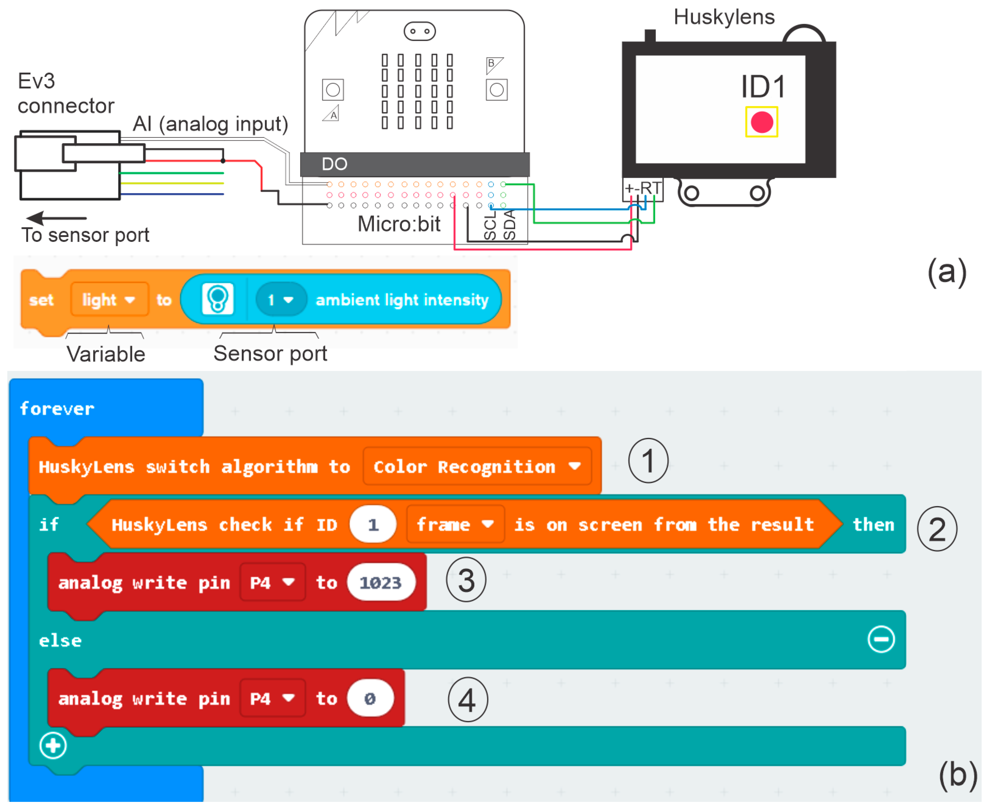
Figure 4a shows the connection diagram between the machine vision camera, the micro:bit and the Ev3 connector that will send an analog input signal to the smart brick when the variable “ID1” is not detected (there is a preset minimum intensity in color detection that makes the camera unable to detect an object. This threshold cannot be modified by the user), as if it came from an Ev3 color sensor (ambient light intensity in port 1).
Figure 4b shows a section of the block code used to choose the color recognition function programmed in MakeCode for the micro:bit (
Figure 4b-1) and the verification of its detection using the variable ID1 (
Figure 4b-2). If this identification was carried out successfully, an analog signal will be sent to an output port of the micro:bit with a value of 1023 (
Figure 4b-3); otherwise, the analog output signal will have a value of 0 (
Figure 4b-4).
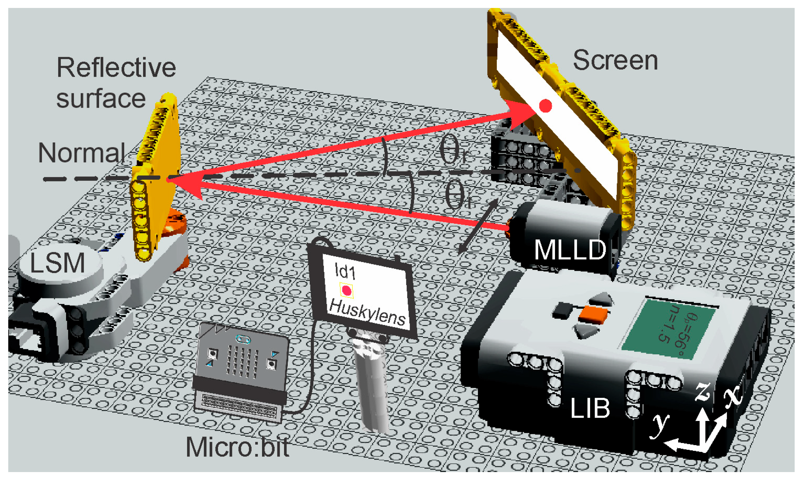
The general schematic setup of the proposed implementation is depicted in
Figure 5. This figure shows the most important parts of the experimental setup, such as the modified Lego laser diode (MLDD, with its polarization parallel to the surface), the smart brick (LIB), the servomotor (LSM), the observation screen, the micro:bit board and the machine vision camera (Huskylens). The normal to the surface under test, the incident angle, and the reflected angle of the beam displayed on a screen are also shown.
By knowing the polarization angle
at which the intensity of the reflected beam is almost zero, and according to the conditions of the experiment
(air as the first medium), it is possible to estimate the refractive index of the object under test by solving
from Equation (6).
Once is detected, the LSM will return to its initial position, waiting to repeat the experiment with the same or another reflective surface. The calculation of and the refractive index of the material () will be displayed on the Ev3 Smart Brick screen, avoiding the use of additional electronic components.
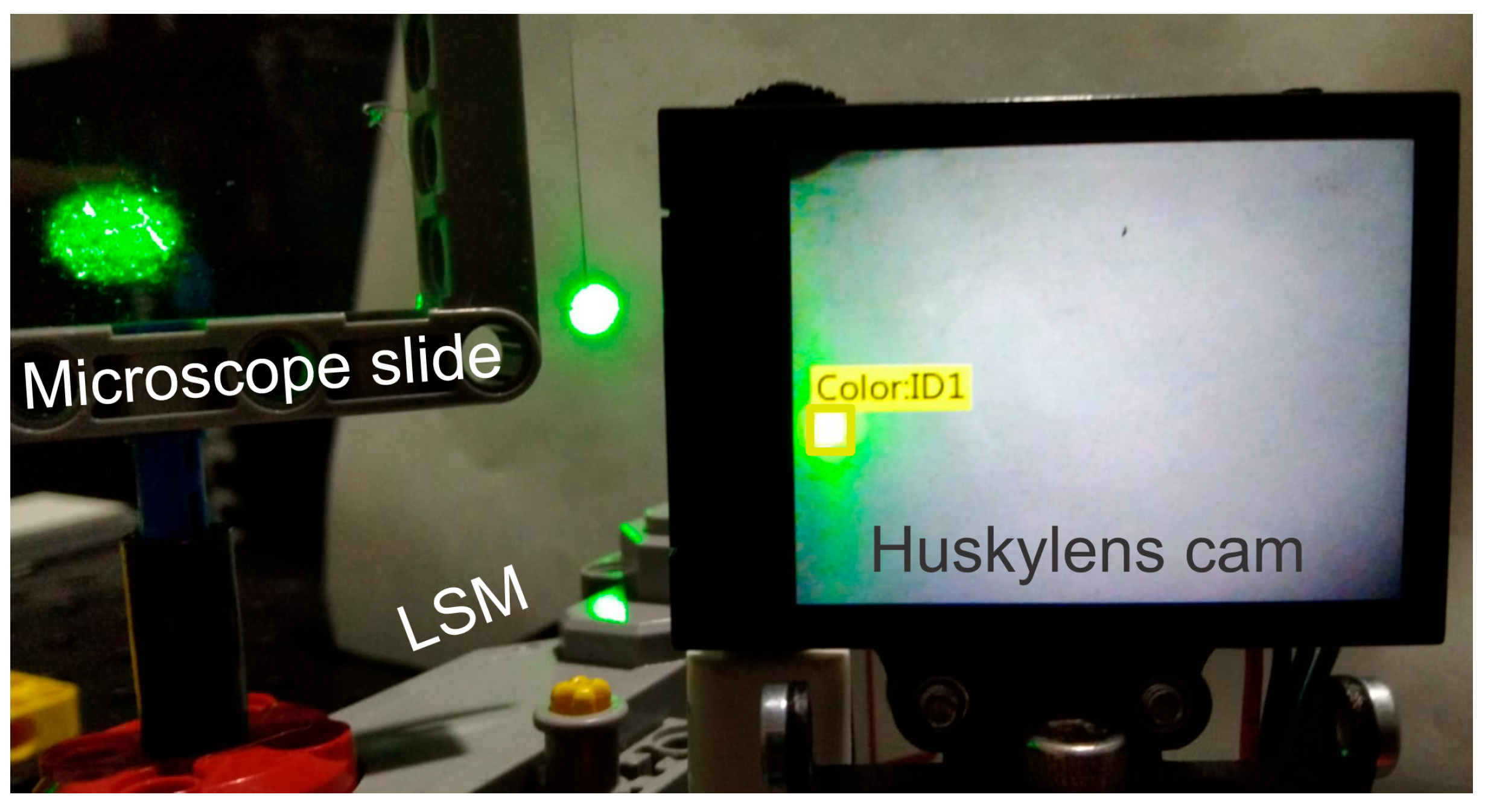
Figure 6 shows the section of the experimental setup where the beam reflected on a screen is detected by the camera using the “color detector” mode, enclosing the laser spot in a yellow rectangle and giving it the variable name “ID1”. This figure also shows part of the Lego servomotor, as well as the microscope slide used as a test object.
It is important to clarify that the field of view of the camera is not wide enough to capture the entire path traveled by the beam until it extinguishes and becomes intense again. To solve this issue, the initial position of the camera has been taken experimentally from where the laser spot appears on its screen (for this particular case, at 36° with respect to the normal to the surface under test) to where it disappears. Thus, 36° will be added to the angle at which the reflected beam extinguishes to obtain the polarization angle.
The LIB and the micro:bit board were used as control elements, programmed in block coding using “Education EV3 classroom” and Makecode, respectively. This programming method has been intentionally chosen because, in a didactic approach, it is simpler for the user to capture the algorithm in blocks than to remember the syntax of a specific language.
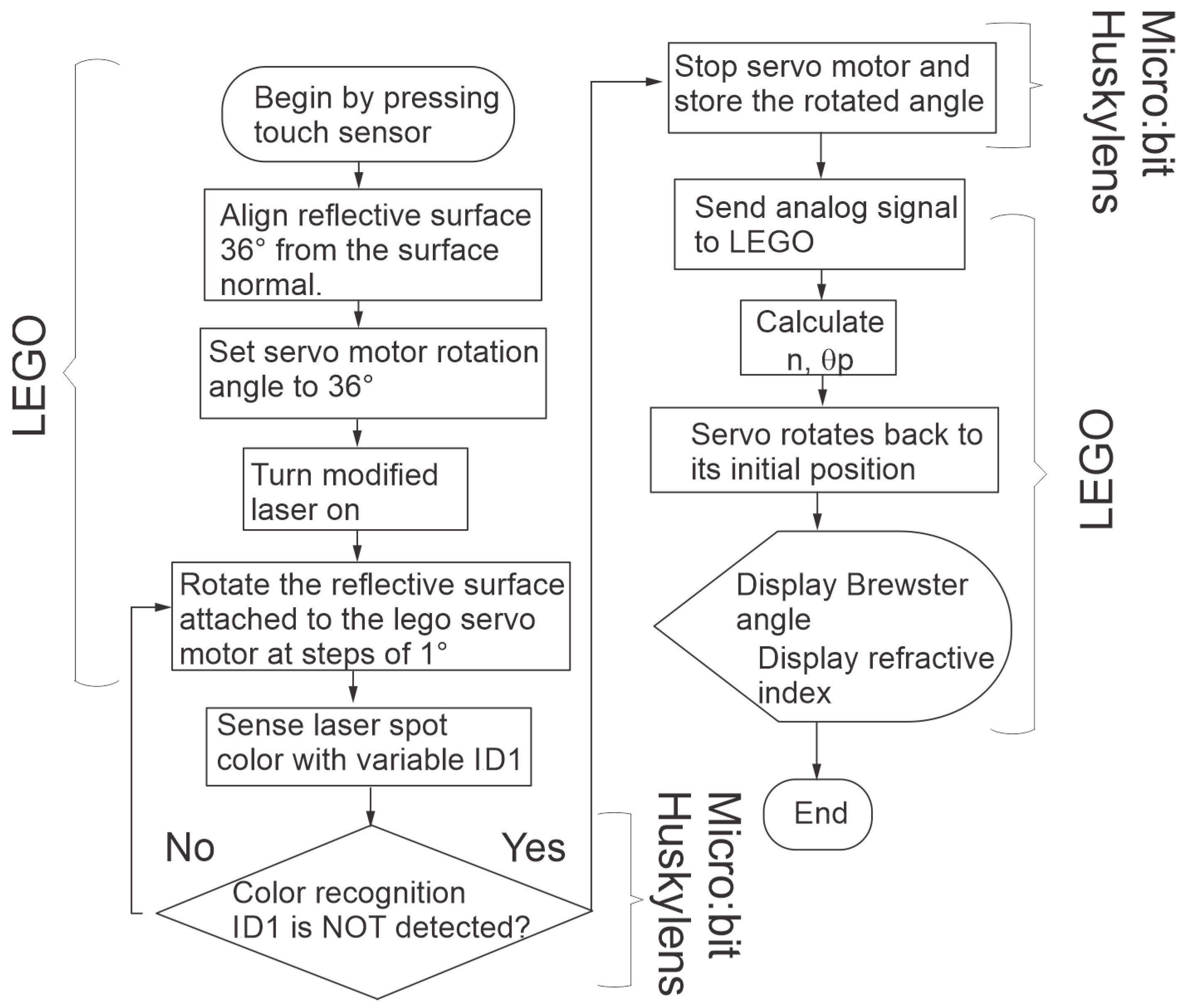
The flow chart shown in
Figure 7 refers to the general steps of the algorithm used to calculate and display the Brewster’s angle, as well as the refractive index of the material under test, pointing out the steps that are carried out by the smart brick and those carried out by the camera in conjunction with the micro:bit.
A simulation of the prototype’s operation can be seen in Media1. The assembly of the Lego blocks (
Figure 5) was carried out in the “LEGO digital designer v.4.3” software. If required, the codes used for the Lego and the micro:bit (the Huskylens camera has to be added as an extension) can be downloaded from the following link
https://www.dropbox.com/scl/fo/lrctt7vk1iqwnmn34ior5/h?rlkey=f6q1hkuuwon2e3t4a6imx91gd&dl=0 (copy and paste the link in a web browser). The file Brewster.lmsp corresponds to the programming of the Lego smart block on the EV3 classroom platform, while Husky_lens.hex contains the camera programming on the Makecode platform.
4. Experimental Results
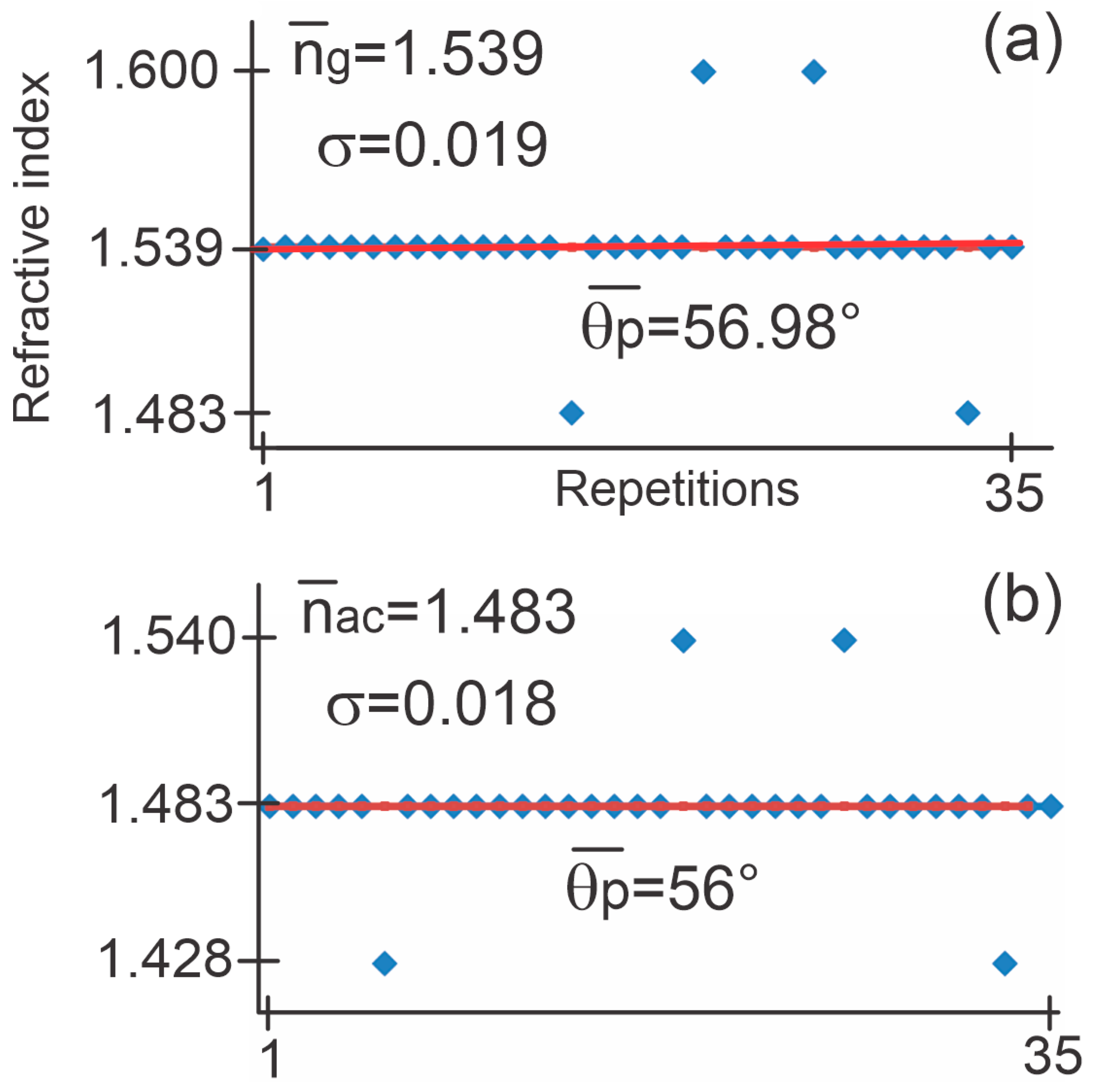
In order to show the viability and repeatability of the presented method, the following graphs show 35 repetitions corresponding to the estimation of the polarization angle as well as the refractive index of the two materials under test: glass and acrylic, respectively. The obtained data were compared with their nominal value, n
g = 1.51 and n
ac = 1.49, found in the literature. Considering these theoretical values with respect to the average of each set of measurements, the error presented when measuring the microscope slide is
. The error corresponding to the acrylic prism is
. These results show a reliable system since generally, an error rate < 5% is accepted for a good educational measurement system [
13]. Therefore, according to the calculated percentage error, it is possible to conclude that the proposal presents a simple and feasible methodology to estimate the polarization angle and the refractive index of a material.
The experimental data are shown in
Figure 8, also indicating the average and the standard deviation
regarding to the refractive index, as well as the average of
corresponding to glass (
Figure 8a) and acrylic (
Figure 8b). During these tests, the entire process was followed by different physics and engineering students in order to guarantee that the whole resource was easy, interesting and practical to use (for this purpose, the “direct observation” technique was used as an exploratory method to qualitatively evaluate the usefulness and impact that the proposed tool had on the students. This was based on observing and taking notes on the students’ behavior while using the tool, paying attention to their level of participation, understanding of the concepts, and any technical difficulties that might arise).
One of the reasons the data shown in the previous figure diverge from the average is because the shaft inserted in the servomotor (which holds the test object) sometimes presents unwanted vibrations, increasing or decreasing tenths of degree in the detected polarization angle, thus affecting the calculation of and .
The device requires a prior calibration stage in which the camera must “learn” to detect the color of the laser spot to save its detection in the assigned variable “ID1”. This process should be performed when the position of any mechanical component or ambient light conditions changed, which may affect the angle and color detection, respectively.
5. Discussion
The materials and methods used in this proposal were chosen because they are visually and functionally attractive to students, in addition to being commonly used for educational and teaching purposes. It was exemplified that these components also have the potential to be applied in physics or engineering implementations under certain modifications but also considering the error in the results that they can produce. In addition, programming in blocks such as that used for the camera, the micro:bit and the Ev3 allows processes to be coded in a simpler and more intuitive way without, the need to learn specific syntaxes of some programming language.
In order to test the resource, two groups of four students worked with the pre-assembled instrument. Some students had problems calibrating the camera correctly, but they managed to solve it with the help of the instructor. All of them showed a high level of participation and curiosity during the experiment, and we observed good collaboration as a team, especially in solving technical problems (such as in camera alignment) and interpreting the results. Regarding the understanding of concepts, the students were able to apply the theoretical concepts of optics to measure the Brewster’s angle and the refractive index successfully, asking questions and discussing the theory involved. Thus, direct observation suggests that the proposal is effective in improving students’ understanding of optics concepts. Active participation and collaboration were high, and technical challenges were overcome with creativity and instructor support.
It is worth mentioning that the main advantages of automation and the use of electronic components chosen for this purpose, as well as the application of this resource as a teaching/learning tool, can be summarized as follows:
- -
It promotes collaborative work by integrating a multidisciplinary approach into the project.
- -
It demonstrates that elements that are generally used for teaching purposes, such as Lego Ev3, can be used in applications for different areas and for scientific purposes. In addition, they can be interfaced with other electronic elements under certain modifications.
- -
It was shown that some preloaded applications of AI [
14,
15] cameras can be used in scientific applications through simple adjustments to the algorithms.
- -
Since the tool is automated, it can be implemented in remote laboratories [
16,
17].
- -
The multiple measurements carried out automatically make it possible to prove the viability of the process.
Although the tool presented is applicable for undergraduate or graduate levels, due to the exposed characteristics, it can also be used as a demonstration tool in basic-level grades and laboratories such as Makerspaces [
18]. The materials, such as LEGO Mindstorms, were chosen because many electronics and robotics laboratories and workshops at undergraduate or graduate levels use them as teaching support materials for topics related to these areas. Taking advantage of this situation, it was shown that through some electronic adaptations, it is possible to use Mindstorms models such as NXT, Ev3 or even Spike and Robot Inventor in applications related to other areas and for different purposes. This also promotes the acquisition and application of knowledge in electronics to make relevant circuits, to achieve interfaces with other boards and devices. Generally, these types of test or optical setups are performed using expensive optical materials and mounts, which makes them difficult to acquire and apply in some educational centers. Therefore, if the reader relies on the methodology presented here, costs can be considerably reduced by using the materials mentioned here or alternatives such as Arduino cards, motor controllers and low-cost and low-torque servomotors.
6. Conclusions
An automated tool based on an AI camera, a micro:bit board, and Lego Mindstorms EV3 elements has been presented. This tool estimates the polarization angle and refractive index of semi-transparent objects by detecting the color of the reflected laser spot using the Huskylens camera feature. This implementation significantly improves upon traditional techniques, which often require the manual detection of beam extinction or mechanical mounts to position the detector in front of the reflected beam. Additionally, with certain modifications, this tool can be improved to be used as a remote laboratory. This alternative would involve the use of a Wi-Fi module (considering that the micro:bit board already includes a Bluetooth module) and a mobile or web application. A suggestion could be the use of app inventor, which is a mobile application development platform created by MIT (Massachusetts Institute of Technology). It allows anyone, even without previous programming experience, to create applications for Android devices in a simple and visual way.
The measurement errors are primarily due to the mechanical vibration of the shaft connected to the test object on the servomotor and illumination variations affecting the detection of the reflected beam. These factors impact the estimation of the critical angle. The precision and accuracy of the proposed method can be enhanced by using mechanical elements with less hysteresis or reduced vibration effects, while maintaining the implementation principle outlined in this manuscript. Another source of error is the minimum angular increment of the EV3 motor, which is 1°. This can be mitigated by implementing a gear train to connect the motor shaft with the test object, though this may introduce additional vibrations. However, variations in environmental conditions such as temperature and humidity do not affect the experiment results.
Finally, it is worth noting that the functions integrated into some artificial intelligence cameras, such as the one used in this implementation, can be used in applications related to the measurement and detection of physical parameters such as the wavelength of a laser source and the refractive index of liquids [
15,
19].


