Article

Experimental Study on Hydrogen Embrittlement-Enhanced Ultrasonic Machining of Inconel 718 Small Hole

by
Sisi Li
1,2,
Shanshan Wen
1,
Jiaping Qiao
3 and
Ming Feng
1,*
1
College of Mechanical and Electrical Engineering, Wenzhou University, Wenzhou 325035, China
2
Rui’an Graduate College, Wenzhou University, Wenzhou 325206, China
3
Shenzhen KiSONICS Technology Co., Ltd., Shenzhen 518000, China
*
Author to whom correspondence should be addressed.
Appl. Sci. 2024, 14(20), 9319; https://doi.org/10.3390/app14209319
Submission received: 30 August 2024 / Revised: 9 October 2024 / Accepted: 10 October 2024 / Published: 12 October 2024

Abstract

:
Small-hole components of Inconel 718 are widely used in aerospace engineering, medical devices, and other fields. Limited by material properties, its machining efficiency seriously restricts its wide application. The objective of this study is to investigate a novel machining technique for Inconel 718 that integrates ultrasonic machining (UM) and hydrogen embrittlement (HE) treatment. Accordingly, the technique is designated as hydrogen embrittlement-enhanced ultrasonic machining (HEUM). Prior to machining, a stress layer is formed on the surface of the workpiece. To ascertain the fundamental characteristics of Inconel 718, the influences of ultrasonic amplitude, HE time, and HE voltage on the specific material removal rate and surface roughness in the presence of HE were empirically examined. To investigate the material removal process for HEUM, the nanoscratch test and nanoindenter were also conducted with HE samples. Further, the subsurface for HEUAG samples were obtained with SEM. The specific material removal rate under experimental conditions of 10 min and 5 V HE increased by 27.4%. Finally, HEUM is proposed to be used for a 1 mm through-hole with Ra 0.318 μm. A precision hole with a diameter as small as 0.5 mm has been manufactured.

1. Introduction

Inconel 718 is highly valued in the fields of aerospace engines and gas turbines due to its excellent high-temperature strength, good thermal stability, and excellent fatigue resistance [1,2]. However, it has severe grain boundary embrittlement at room and elevated temperatures, and the precipitation process may produce phase boundaries (PBs) of characteristic structures due to atomic diffusion [3]. Small-hole components of Inconel 718, with seemingly simple structures, play a crucial role and have been widely used in fields such as aerospace engineering, medical devices, and energy and chemical industries [4,5,6].
To satisfy the precision machining requirements of small holes, small tool CNC machining is generally employed to improve the dimensional and shape accuracy of small-hole components. Machining processes for small holes typically utilize tools with diameters of less than 1 mm. Due to these extremely small sizes, one of the primary reasons for tool failure is breakage, which often results from excessive thrust force or torque [7]. Inconel 718 is widely recognized as one of the most difficult materials to machine, attributed to its remarkable tensile strength and poor thermal conductivity [8]. For decades, the machining process has been a significant area of research [9,10,11,12,13]. To enhance the machining efficiency of small holes in Inconel 718, Hang Dong et al. [14] introduced a novel water-oil (W/O) nanoemulsion dielectric for high-speed grinding of this alloy. The research focused on evaluating the material removal rate (MRR) and the relative electrode wear rate. Findings revealed that the application of this innovative coolant during high-speed grinding increased the material removal rate, decreased the relative electrode wear rate, and improved surface quality. Devillez et al. [9] investigated methods to lower production costs by eliminating cutting fluids, conducting experiments under dry machining conditions with both coated and uncoated carbide tools. The coated carbide tool minimized welding and the formation of unstable built-up edges while also decreasing abrasive wear. Ryoichiro Kishi et al. [15] compared electrochemical machining (ECM) with EDM. The surface roughness of the rectangular groove was improved from Ra 3.82 μm to Ra 0.86 μm after ECM. The material removal rate of ECM was determined using an L9 orthogonal array based on the Taguchi technique [16]. The optimal parameters identified to maximize the MRR were a current of four amps, a voltage of 18 V, and an electrolyte concentration of 60 g/L. However, the disadvantage of EDM is that the EDM discharge leads to rapid wear of the tool electrodes. Therefore, Zhu et al. [17] present a hybrid process of grinding and electrochemical removal for the precision machining of small holes. The surface finish after machining was improved to Ra 1.25 μm. Therefore, tool wear is effectively suppressed, and surface quality is improved. Therefore, in the conventional small hole machining process, low efficiency, low material removal rate, and rapid wheel wear are often observed.
Unlike other machining processes, ultrasonic machining (UM) typically produces workpieces with excellent surface finish and high dimensional accuracy, even when dealing with difficult-to-machine materials. This is achieved because the material removal process involves the use of extremely fine and hard abrasive particles that are capable of efficiently cutting through tough and brittle materials [18]. Kuriakose et al. [19] utilized UM to machine micropores in Zr-Cu-Ti metallic glass and found that UM does not affect the amorphous morphology of metallic glass. The quality of the small hole was observed to be very good in the higher feed rate and with the use of abrasive slurry with abrasives of a higher grit number. However, Inconel 718 has a high tearing modulus; its material removal in UM can only rely on shear, material fracture, and material displacement rather than through plastic deformation removal. In UM, the material removal rate of Inconel 718 was seriously reduced.
To improve the material removal rate through the UM method, this study conducted hydrogen embrittlement (HE) for Inconel 718. Hydrogen embrittlement, the most common form of metal failure, limits many high-strength alloy applications. Hydrogen usually comes from the environment in which it is used and when it is absorbed by the alloy, it is randomly dispersed and eventually trapped by defects, dislocations, etc. The trapped hydrogen becomes enriched over time, weakening interfacial bonding, known as hydrogen-enhanced debonding (HEDE), and promoting dislocation motion, known as hydrogen-enhanced local plasticity (HELP) [20]. The chemical composition of the Inconel 718 alloy is shown in Table 1. The Inconel 718 alloy, after being subjected to HE, exhibits reduced ductility, making it more suitable for UM material removal. Rezende et al. [21] reported that the mechanical properties of Inconel 718 alloy were deteriorated in the presence of hydrogen. Li et al. [22] analyzed the HE behavior of Inconel 718 at room temperature through slow-strain-rate tensile tests, TEM, and SEM, and the results showed that Inconel 718 exhibited the Portevin–Le Chatelier (PLC) effect at current densities of 220 mA/cm2 and 590 mA/cm2. Xu et al. [23] observed mixed cracks on the fracture surface of Inconel 718 after HE modification, making it easier to machine by the UM method.
To enhance the material removal rate of Inconel 718, this study introduces a hybrid material removal technique known as “hydrogen embrittlement enhanced ultrasonic machining (HEUM)”. The influence of machining parameters on the specific material removal rate and surface roughness is examined through experiments. In order to explore the sidewall material removal mechanism, nanoscratch testing was performed on HEUM samples with reference to the study by Xu Long et al. [24] to simulate a single abrasive machining process. The material removal mechanism of HEUM is analyzed by examining results from nanoindenter tests and the morphology of the bottom surface of blind holes. This research holds significant implications for the HEUM strategy and the precise small hole machining of Inconel 718.

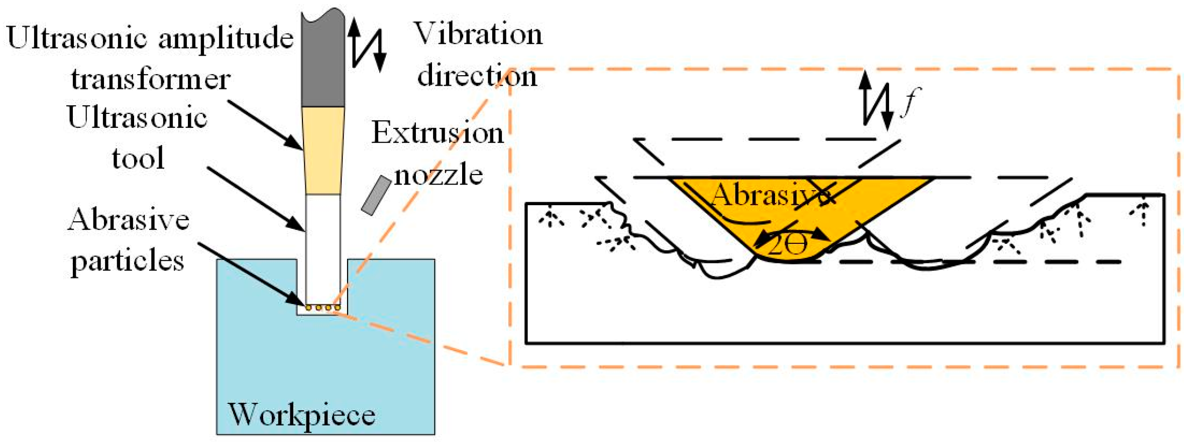
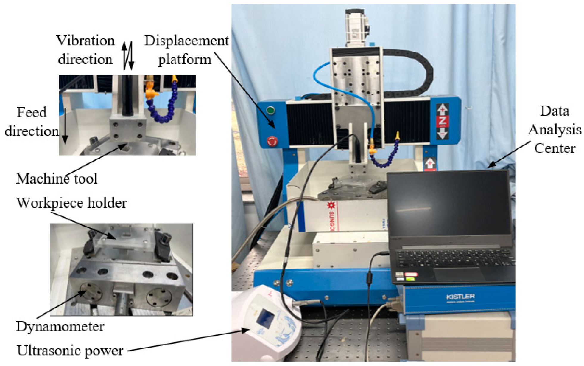
2. Processing Principle and Experimental Details

Figure 1 exhibits the machining principle of the proposed HEUM method. The HEUM process was divided into two stages. In the first stage, the hydrogen embrittlement treatment of a workpiece is carried out; then, in the second stage, the treated workpiece is taken for machining. The hydrogen embrittlement treatment is carried out for 0–40 min in a phosphoric acid solution of 98 g/L, with the voltage of the regulated power supply set to 0–20 V. The effect of hydrogen embrittlement on the organization of the Inconel 718 alloy is irreversible, and the maximum hydrogen diffusion depth can be calculated to be about 9.80 um according to Li et al. [22]. During the machining, a WC machining tool (Shenzhen KiSONICS Technology Co., Ltd., Shenzhen, China) with a diameter of 0.5 mm underwent ultrasonic vibrations at a frequency of 40 kHz in its own axis. The experimental parameters are shown in Table 2, where the tool diameter was 0.5 mm, the amplitude was 2.28–9.3 μm, the hydrogen embrittlement s time was 0–40 min, the hydrogen embrittlement voltage was 0–20 V, the feed rate was 20 μm/min, the set depth of the observation pattern was 0.1 mm, and the set depth of the through-hole was 1.5 mm. A machine fluid nozzle was employed to supply the free abrasive particles into the machine zone with a given flow. The Inconel 718 specimen with dimensions of L40 × W40 × T1 mm was fixed on the workpiece fixture as a workpiece. As shown in Figure 2, the HEUM setup was established in this experiment by installing an ultrasonic tool on a three-axis moving platform. The physical drawing of the workpiece is shown in Figure 3, where the yellow-colored square area is the machining area, the size of which is 10 × 10 mm. Figure 4 shows a schematic diagram of a through-hole machined in one pass taken by laser confocal microscopy.
The ultrasonic amplitude was measured using laser multi-frequency interferometry (Polytec Co., Ltd., Waldbronn, Germany). The relationship between voltage and amplitude is shown in Figure 5. The ultrasonic transducer designed in this study was capable of achieving stable ultrasonic vibration, with the primary vibration direction along the z-axis. The ultrasonic amplitude in the other axis was negligible. The ultrasonic voltage and amplitude exhibit a linear relationship, with a maximum amplitude of 9.3 μm.
The tool wear and material removal depth were measured using a laser confocal microscope (Olympus Co., Ltd., Tokyo, Japan). In order to simulate the single abrasive machining of the sidewall, nanoscratch tests (Anton-Paar Co., Ltd., Graz, Austria) were carried out with HE samples. In the nanoscratch experiment, the indenter’s load was incrementally raised to a specified value, while the diamond grain (B-T74) was advanced at a scratching rate of 5000 μm/min with a peak load of 20 mN and a loading rate of 0.1 mN/s at a scratch length of 1000 μm. This process resulted in the formation of a groove, the depth of which increased progressively. This behavior resembled the microcutting action exhibited by a single grain in HEUM. For comparative analysis, a non-treated workpiece was also subjected to testing. The morphological features were analyzed using a scanning electron microscope (SEM) manufactured by Zeiss Co., Ltd. in Oberkochen, Germany. Following this, the hardness was evaluated using a commercial nanoindenter (Shimadzu Co., Ltd., Kyoto, Japan) at a peak load of 10 mN and a loading speed of 0.2926 mN/s, employing a Vickers indenter. To provide a preliminary assessment of the relationship between the reduction in hardness and the decrease in total dislocation density in the HE sample during the nanoindentation process, the hardness was expressed as follows [25]:
H = 3 3 α μ b ρ T
where α is a constant, μ is the shear modulus, b is the Burgers vector, and ρT is the total dislocation density.

3. Experimental Results and Discussion

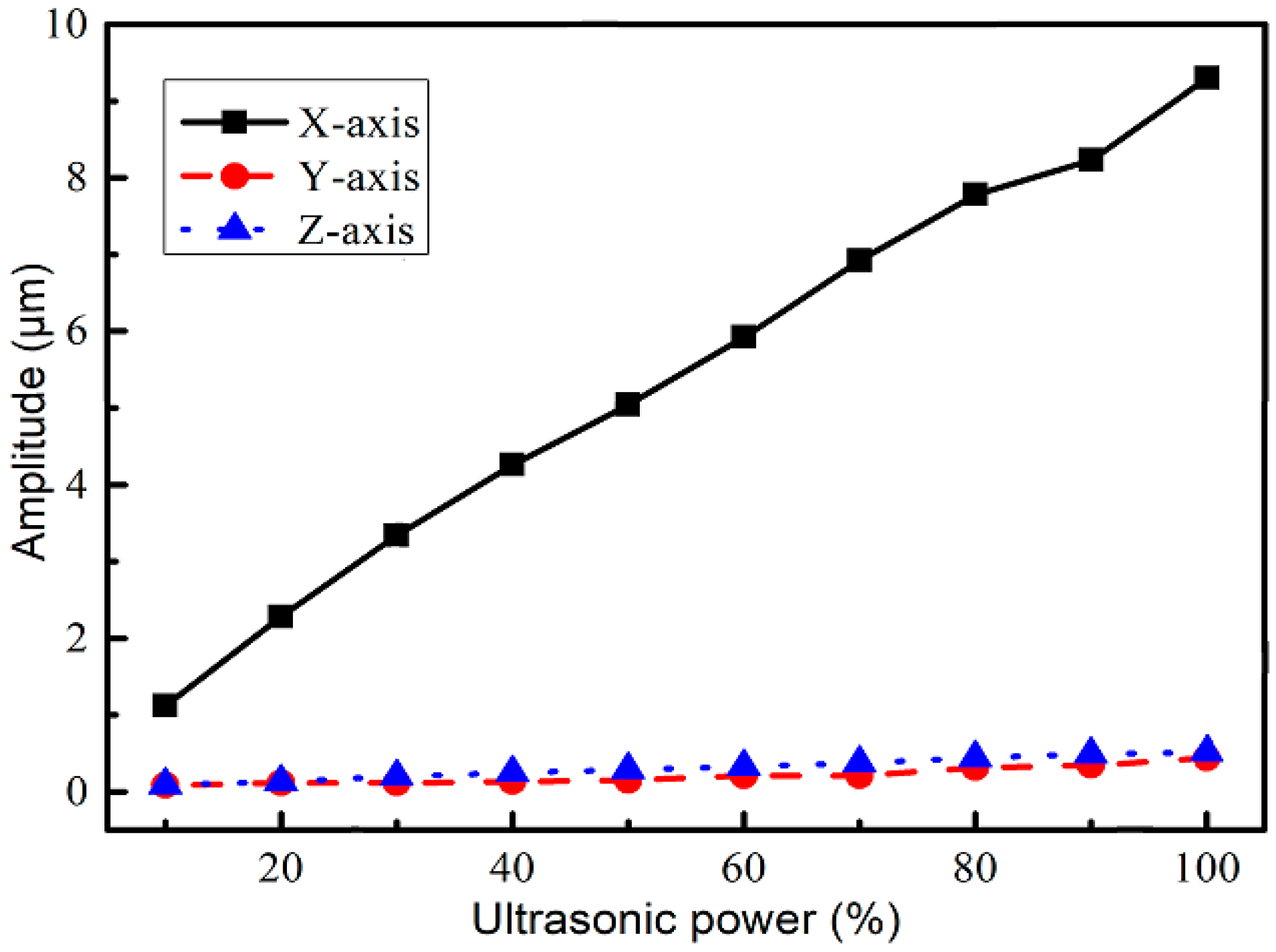
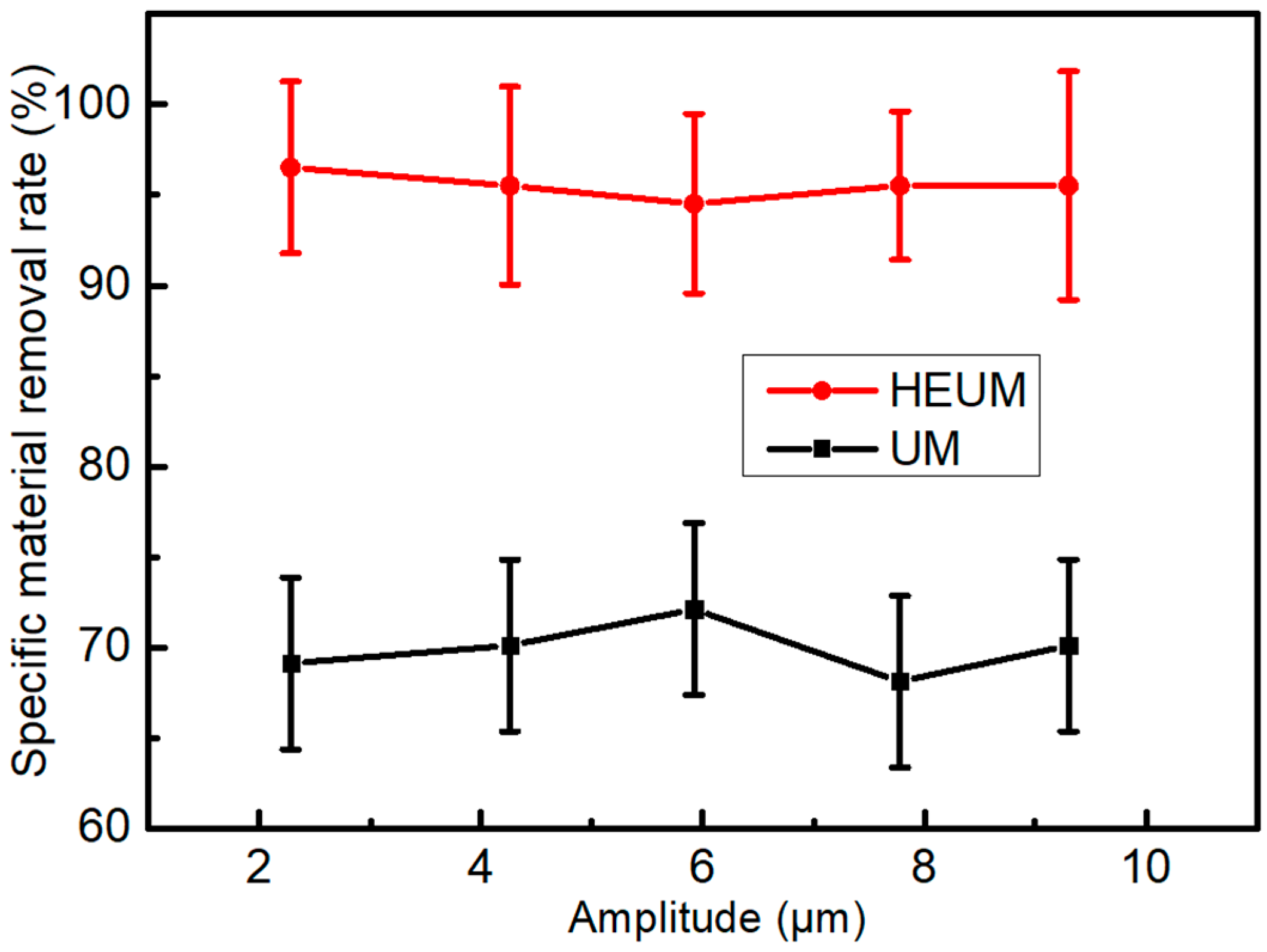
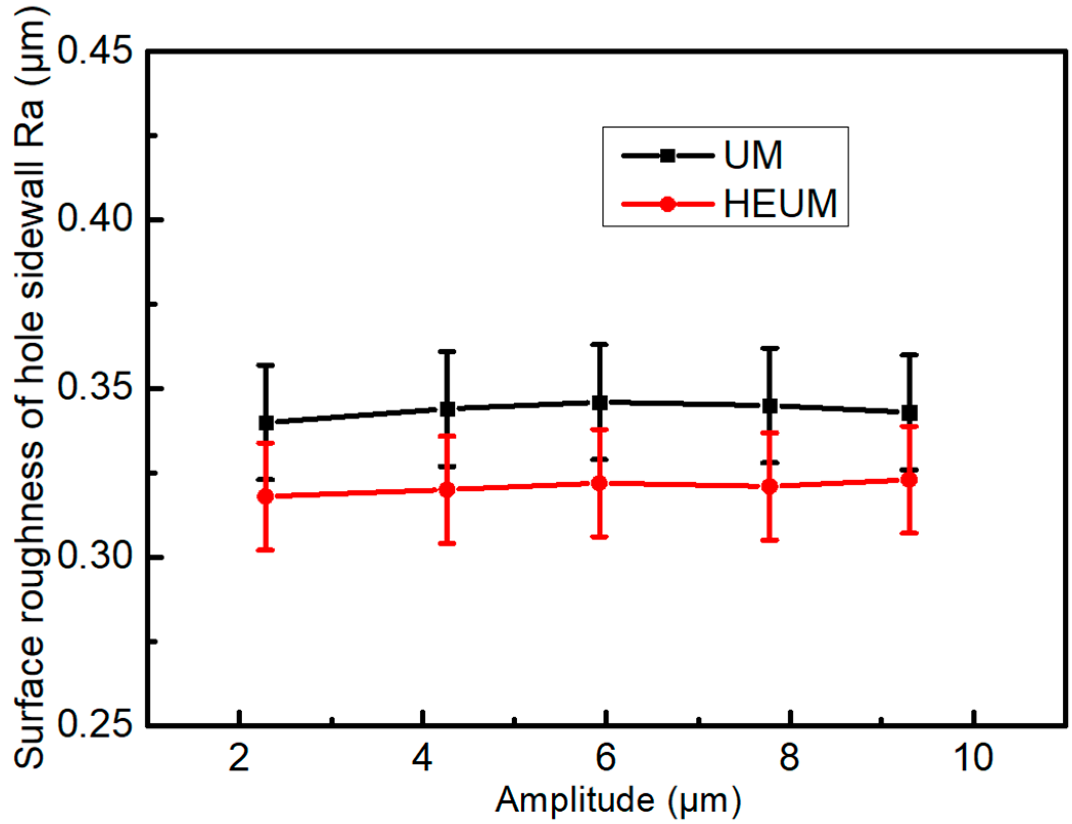
3.1. The Effect of Ultrasonic Processing Parameters on Specific Material Removal Rate and Surface Roughness

In HEUM, the primary method for material removal relied on the ultrasonic vibrations of the tool driving the abrasive particles. During the machining process, the abrasive particles not only removed material through impact but also caused wear on the machining tool. Therefore, when discussing the material removal rate, it was necessary to consider tool wear to reflect changes in machining efficiency accurately. This work used the specific material removal rate to characterize the impact of HE on machining efficiency. Specific material removal rates were defined as
η = l r Δ l Δ r × 100 %
where ∆r was the actual removal depth, ∆ was the setting depth, lr was the tool length after machining, and l was the tool’s original length.
The specific material removal rate under different ultrasonic amplitudes is shown in Figure 6. Regardless of the presence of HE, the specific material removal rate increased with the increase in ultrasonic amplitude. Compared with ultrasonic machining for the original workpiece, the introduction of HE could increase the specific material removal rate by up to 30%. The main reason is related to the quasi-cleavage flat facets that appeared in secondary cracks aligned with the feed direction instead of in the main crack [14]. Meanwhile, compared with the original workpiece, the HE workpiece shows low ductility, which is beneficial for improving machining efficiency [26].
During machining through-holes, the effects of ultrasonic amplitude on the surface roughness of the sidewalls are shown in Figure 7. The changes in surface roughness of the sidewalls were not significant for both machining methods. Compared with the original workpiece, the surface roughness after HE was consistently lower, which was reduced from 0.34 μm to 0.318 μm, which was a relatively smooth surface for the application [27].
Scratching grooves were observed by SEM; the result is shown in Figure 8. There is obviously material piling up on both sides of the groove in the original samples (Figure 8a–c), while in the HE samples (Figure 8d–f) comparation, there is none or little material piling up. As illustrated in Figure 8d–f, the surface quality remained high in the initial section of the groove. In the middle section, while there were minimal signs of burrs and material brittleness removal, the surface quality was still satisfactory, although a few micro honeycomb structures (Figure 8e) were noted within the groove. At the end of the groove, the removal of brittle material was clearly evident (Figure 8f), contrasting with the burrs that covered the end (Figure 8c). Overall, the surface quality throughout the rest of the groove was good. During the ultrasonic machining process, HE effectively minimized burr formation in the samples, ensuring consistently good surface quality.

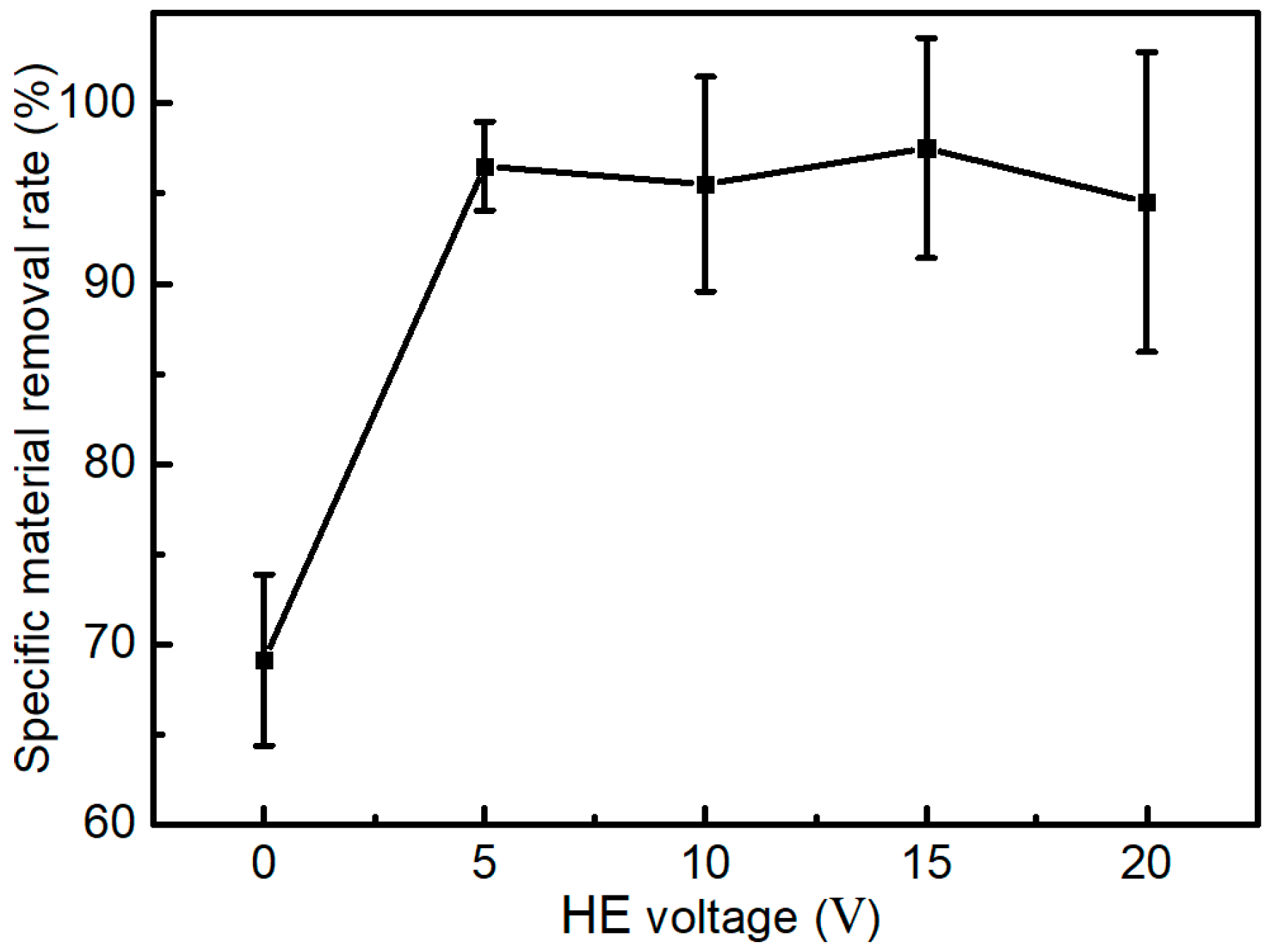
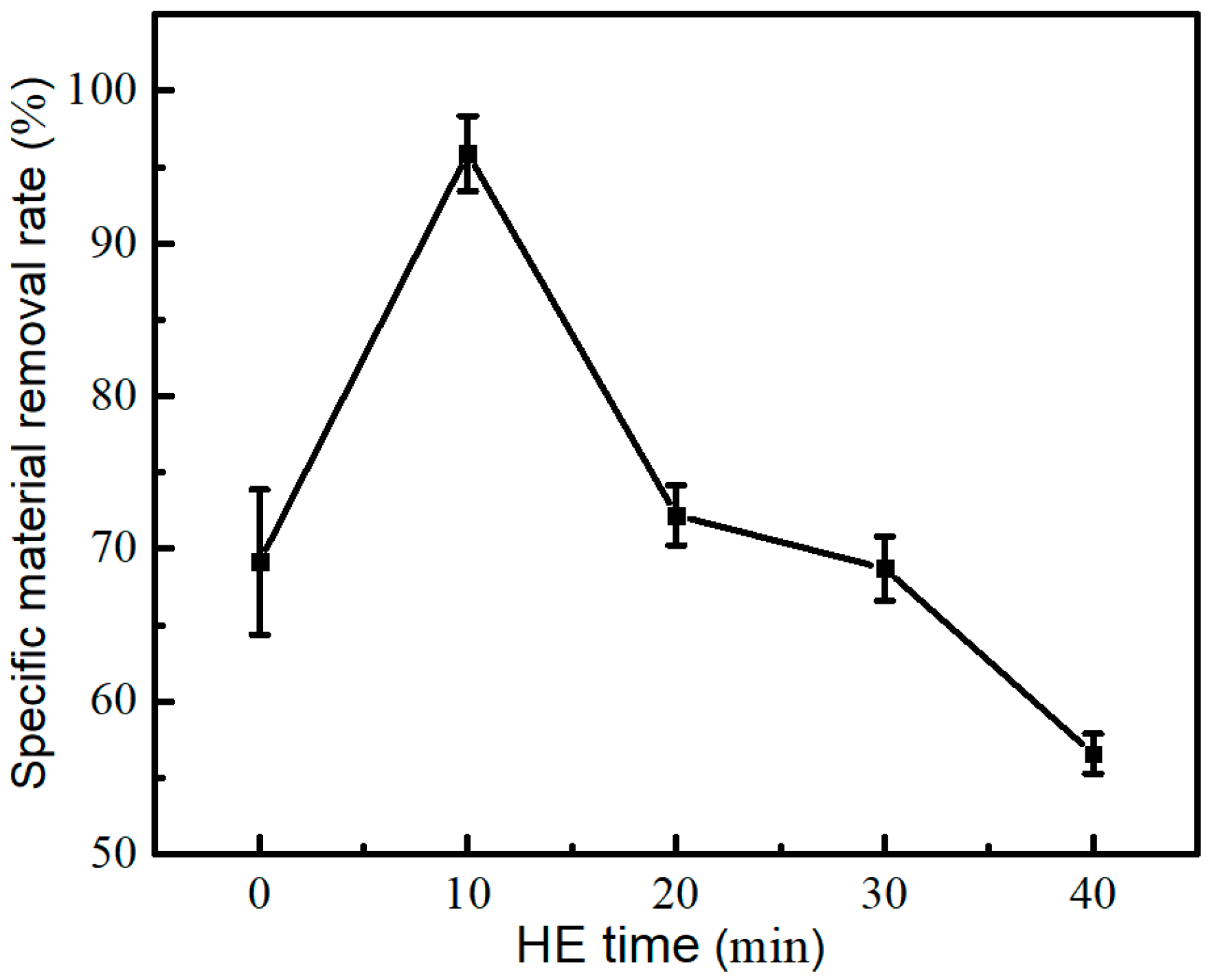
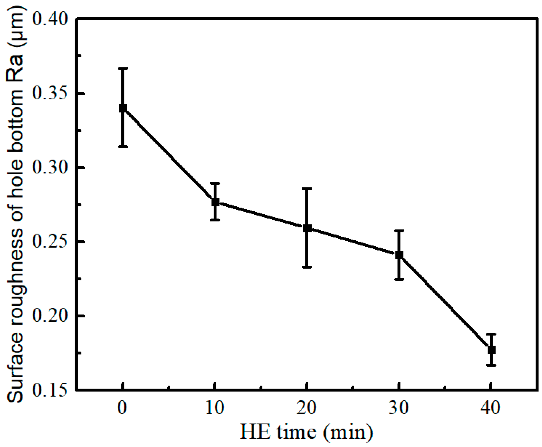
3.2. The Effect of HE Parameters on Specific Material Removal Rate and Surface Roughness

The effects of HE voltage on specific material removal rates are shown in Figure 9. The specific material removal rate (96.5%) of Inconel 718 with HE treatment under 5 V was much higher than that of the original workpiece (69.1%), and no obvious changes in specific material removal rates were observed with increasing voltage from 5 V to 20 V.
The effects of HE time on specific material removal rate are shown in Figure 10. With the increase in HE time, the specific material removal rate firstly increased and then decreased. It was demonstrated that when the HE time was less than 10 min, HE effectively improved the specific material removal rate from 69.1% to 96.5%. However, the specific material removal rate decreased to 72.2% when extending HE time to 20 min, and the removal rate even dropped to 56.6% when the HE time reached 40 min.
To explore the mechanism of HE time on specific material removal rates, this study investigated the effects of HE time on material hardness, as increasing hardness would increase tool wear and thus reduces specific material removal rates. In this experiment, nanoindentation tests were performed for 10 cycles for each sample, and the load force was 10 mN. As shown in Figure 11, when the HE time was less than 10 min, there is little change in surface hardness. Meanwhile, the plasticity of the Inconel 718 alloy decreased rapidly by 66.1% within 10 min of HE treatment [27]. A large number of stress lines appeared in the subsurface, accompanied by a few microcracks. During the machining process, this subsurface stress is easily released, significantly reducing the energy required for deformation. As a result, compared to the original Inconel 718, the total fracture energy is reduced less. Consequently, the surface of the hydrogenated specimens shows numerous micro fractures. Therefore, the cooperation of lower hardness and plasticity facilitates the improvement in specific material removal rates. As the HE time increased from 10 min to 40 min, the surface hardness dramatically increased from 340 HV to 512 HV. According to Yuanyuan et al. [28], the reason for such a change in hardness is due to the γ’ phase precipitates. The much higher surface hardness overcompensated for the effect from lower plasticity, ultimately leading to a decrease in specific material removal rates.
To investigate the material removal mechanism, a study was conducted on blind hole machining with a depth of 0.1 mm. The roughness at the bottom surface of the blind hole was measured. As shown in Figure 12, when the HE time increased, the surface roughness of the hole bottom decreased. The minimum value of roughness was 0.177 µm at 40 min HE. As shown in Figure 8, better surface quality was obtained with the HE samples. After HEUM, brittleness material removal occurred on the machined surface. To provide more intuitive evidence of the surface roughness, this study used SEM to observe the surface morphology of the blind hole (Figure 13). In the presence of HE treatment, the material removal mode changed to brittle deformation, with only 2 µm long fractures remaining at the bottom surface, and the fracture length was comparable to the abrasive diameter, effectively improving the surface roughness of the hole bottom (Figure 13b–e). In contrast, the material removal mode exhibited plastic deformation, with a large number of residual scratches and abrasive adhesion on the surface after processing without HE treatment (Figure 13a).
In addition, this study explored the effect of HE time on the roughness of the sidewall of the through-hole, as shown in Figure 14. As the HE time increased from 0 to 10 min, the sidewall roughness also decreased from 0.34 to 0.318. When the hydrogen charging time exceeded 10 min, the sidewall roughness tended to stabilize around 0.31 μm, which is not much different from the roughness at 10 min. In conclusion, the HE treatment time should be 10 min, combining machining efficiency and surface quality.

4. Conclusions

Small-hole components of Inconel 718 are widely used in aerospace engineering, medical devices, and other fields. Limited by the material properties of Inconel 718, the machining efficiency of small holes seriously restricts its wide application. Thus, hydrogen embrittlement-enhanced ultrasonic machining, HEUM, was proposed for the efficient machining of a small hole on Inconel 718. The conclusions are as follows:
(1)
HEUM significantly enhanced both machining efficiency and the surface roughness of the hole sidewalls. However, there was no notable change in surface roughness as the ultrasonic amplitude and HE voltage increased.
(2)
Under the experimental conditions, the specific material removal rate improved by 27.4% compared to conventional ultrasonic machining when subjected to 5 V HE for 10 min. This improvement is attributed to the substantial reduction in the plasticity of Inconel 718 after 10 min, which was beneficial for high-efficiency material removal.
(3)
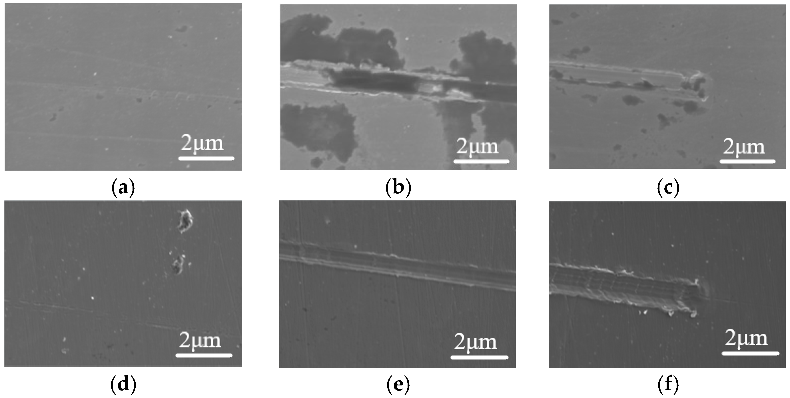
Following the machining of blind holes, surface roughness at the bottom of the holes decreased as the HE time increased. Notably, the area exhibiting brittle fractures at the hole’s bottom expanded with longer HE durations. This change occurs because the mechanism of material removal shifts from plastic deformation to brittle fracture, resulting in a significant enhancement in surface finish quality.
(4)
The optimal processing parameters were determined to be an ultrasonic amplitude of 2.28 μm, an HE voltage of 5 V, and an HE time of 10 min. Under these conditions, a 1 mm through-hole with a surface roughness (Ra) of 0.318 μm can be achieved through HEUM. Therefore, it is obvious that HEUM is a promising method for small-hole machining on hard-to-difficult machining material.

Author Contributions

Conceptualization, S.L.; methodology, S.W. and J.Q.; formal analysis, S.L. and S.W.; investigation, S.L. and J.Q.; data curation, S.W.; writing—original draft preparation, S.L. and M.F.; writing—review and editing, S.L. and M.F.; visualization, J.Q.; supervision, S.L.; project administration, S.L.; funding acquisition, S.L. All authors have read and agreed to the published version of the manuscript.

Funding

This work was funded by the National Natural Science Foundation of China (52105479) and major scientific and technological innovation projects of Wenzhou City (CN) (grant no. ZG2022029).

Institutional Review Board Statement

Not applicable.

Informed Consent Statement

Not applicable.

Data Availability Statement

Data are all contained within the article. All data are fully available without restriction.

Conflicts of Interest

Author Jiaping Qiao was employed by the company Shenzhen KiSONICS Technology Co., Ltd. The remaining authors declare that the research was conducted in the absence of any commercial or financial relationships that could be construed as a potential conflict of interest.

References

  1. Tang, Y.; Zhang, B. Achieving 2.9 GPa yield strength in Inconel 718 alloy with Cr-segregated nanograins. Mater. Sci. Eng. 2024, 896, 146303. [Google Scholar] [CrossRef]
  2. Paturi, U.M.R.; Reddy, N.S. Progress of machinability on the machining of Inconel 718: A comprehensive review on the perception of cleaner machining. Clean. Eng. Technol. 2021, 5, 100323. [Google Scholar] [CrossRef]
  3. Zhao, Y. Stability of phase boundary between L12-Ni3Al phases: A phase field study. Intermetallics 2022, 144, 107528. [Google Scholar] [CrossRef]
  4. Khanafer, K.; Eltaggaz, A.; Deiab, I.; Agarwal, H.; Abdul-latif, A. Toward sustainable micro-drilling of Inconel 718 superalloy using MQL-Nanofluid. Int. J. Adv. Manuf. Technol. 2020, 107, 3459–3469. [Google Scholar] [CrossRef]
  5. Parida, A.K.; Maity, K. Numerical and Experimental Analysis of Specific Cutting Energy in Hot Turning of Inconel 718. Measurement 2019, 133, 361–369. [Google Scholar] [CrossRef]
  6. Unune, D.R.; Nirala, C.K.; Mali, H.S. Accuracy and quality of micro-holes in vibration assisted micro-electro-discharge drilling of Inconel 718. Measurement 2019, 135, 424–437. [Google Scholar] [CrossRef]
  7. Biscaia, R.V.B.; Ribas, M.T.; Júnior, A.B. Effects of processing parameters on the micro-drilling through fast hole electroerosion and laser trepanning in Inconel 718. Int. J. Adv. Manuf. Technol. 2020, 106, 31–45. [Google Scholar] [CrossRef]
  8. Kitagawa, T.; Kubo, A.; Maekawa, K. Temperature and wear of cutting tools in high-speed machining of Inconel 718 and Ti-6Al-6V-2Sn. Wear 1997, 202, 142–148. [Google Scholar] [CrossRef]
  9. Devillez, A.; Schneider, F.; Dominiak, S.; Dudzinski, D.; Larrouquere, D. Cutting forces and wear in dry machining of Inconel 718 with coated carbide tools. Wear 2007, 262, 931–942. [Google Scholar] [CrossRef]
  10. Xu, W.; Zhang, L.; Wu, Y. Elliptic vibration-assisted cutting of fibre-reinforced polymer composites: Understanding the material removal mechanisms. Compos. Sci. Technol. 2014, 92, 103–111. [Google Scholar] [CrossRef]
  11. Welling, D. Results of surface integrity and fatigue study of Wire-EDM compared to broaching and grinding for demanding jet engine components made of Inconel 718. Procedia CIRP 2014, 13, 339–344. [Google Scholar] [CrossRef]
  12. Devillez, A.; Le Coz, G.; Dominiak, S.; Dudzinski, D. Dry machining of Inconel 718, workpiece surface integrity. J. Mater. Process. Technol. 2011, 211, 1590–1598. [Google Scholar] [CrossRef]
  13. Zhena, J.; Li, F.; Zhu, S.; Ma, J.; Qiao, Z.; Liu, W.; Yang, J. Friction and wear behavior of nickel-alloy-based high temperature self-lubricating composites against Si3N4 and Inconel 718. Tribol. Int. 2014, 75, 1–9. [Google Scholar] [CrossRef]
  14. Dong, H.; Liu, Y.; Li, M.; Liu, T.; Zhou, Y.; Li, D.; Shen, Y. High-speed compound sinking machining of Inconel 718 using water in oil nanoemulsion. J. Mater. Process. Technol. 2019, 274, 116271. [Google Scholar] [CrossRef]
  15. Kishi, R.; Yan, J. Electrical Discharge/Electrochemical Hybrid Machining Based on the Same Machine and Tool Electrode. J. Micro-Nano-Manuf. 2020, 8, 010906. [Google Scholar] [CrossRef]
  16. Gobikrishnan, U.; Suresh, P.; Kumaravel, P. Drilling investigations on Inconel alloy 625 material of material removal rate using micro electrochemical machining. Mater. Today Proc. 2021, 37, 1629–1633. [Google Scholar] [CrossRef]
  17. Zhu, D.; Zeng, Y.B.; Xu, Z.Y.; Zhang, X.Y. Precision machining of small holes by the hybrid process of electrochemical removal and grinding. CIRP Ann. 2011, 60, 247–250. [Google Scholar] [CrossRef]
  18. Asmael, M.; Safaei, B.; Zeeshan, Q.; Zargar, O.; Nuhu, A.A. Ultrasonic machining of carbon fiber–reinforced plastic composites: A review. Int. J. Adv. Manuf. Technol. 2021, 113, 3079–3120. [Google Scholar] [CrossRef]
  19. Kuriakosea, S.; Patowaria, P.K.; Bhattba, J. Machinability study of Zr-Cu-Ti metallic glass by micro hole drilling using micro-USM. J. Mater. Process. Technol. 2017, 240, 42–51. [Google Scholar] [CrossRef]
  20. Zhang, Y.; Ye, Q.; Yan, Y. Processing, microstructure, mechanical properties, and hydrogen embrittlement of medium-Mn steels: A review. J. Mater. Sci. Technol. 2024, 201, 44–57. [Google Scholar] [CrossRef]
  21. Rezende, M.C.; Araujo, L.S.; Gabriel, S.B.; Santos, D.S.D.; de Almeida, L.H. Hydrogen embrittlement in nickel-based superalloy 718: Relationship between γ′ + γ″ precipitation and the fracture mode. Int. J. Hydrogen Energy 2015, 40, 17075–17083. [Google Scholar] [CrossRef]
  22. Li, X.; Zhang, J.; Akiyama, E.; Fu, Q.; Li, Q. Hydrogen embrittlement behavior of Inconel 718 alloy at room temperature. J. Mater. Sci. Technol. 2019, 35, 499–502. [Google Scholar] [CrossRef]
  23. Zhao, B.; Chang, B.; Wang, X.; Bie, W. System design and experimental research on ultrasonic assisted elliptical vibration grinding of Nano-ZrO2 ceramics. Ceram. Int. 2019, 45, 24865–24877. [Google Scholar] [CrossRef]
  24. Long, X.; Shen, Z.; Li, J.; Dong, R.; Liu, M.; Su, Y.; Chen, C. Size effect of nickel-based single crystal superalloy revealed by nanoindentation with low strain rates. J. Mater. Res. Technol. 2024, 29, 2437–2447. [Google Scholar] [CrossRef]
  25. Sampath, D.; Akid, R.; Morana, R. Estimation of crack initiation stress and local fracture toughness of Ni-alloys 945X (UNS N09946) and 718 (UNS N07718) under a hydrogen environment via fracture surface topography analysis. Eng. Fract. Mech. 2018, 191, 324–343. [Google Scholar] [CrossRef]
  26. Lu, X.; Ma, Y.; Wang, D. On the hydrogen embrittlement behavior of nickel-based alloys: Alloys 718 and 725. Mater. Sci. Eng. A 2020, 792, 139785. [Google Scholar] [CrossRef]
  27. Hou, S.; Bai, J.; Tian, B.; Liu, H. Experimental investigation to improve the efficiency and surface integrity of deep micro-hole machined by micro-EDM. Int. J. Adv. Manuf. Technol. 2022, 123, 2249–2259. [Google Scholar] [CrossRef]
  28. Song, Y.; Zhao, M.; Rong, L. Study on the Precipitation of γ’ in a Fe-Ni Base Alloy During Ageing by APT. Acta Metall. Sin. 2018, 54, 1236–1244. [Google Scholar] [CrossRef]
Figure 1. Schematic diagram of HEUM.
Applsci 14 09319 g001
Figure 2. Experimental setup.
Applsci 14 09319 g002
Figure 3. Inconel 718 workpiece.
Applsci 14 09319 g003
Figure 4. Through-hole schematic.
Applsci 14 09319 g004
Figure 5. The effect of ultrasonic power on ultrasound amplitude.
Applsci 14 09319 g005
Figure 6. The effect of ultrasonic amplitudes on specific material removal rate.
Applsci 14 09319 g006
Figure 7. The effect of ultrasonic amplitudes on surface roughness of the hole sidewall.
Applsci 14 09319 g007
Figure 8. Scratching grooves of Inconel 718 ((a) is the initial portion, (b) is the middle portion, and (c) is the end portion) and 5 V HE samples ((d) is the initial portion, (e) is the middle portion, and (f) is the end portion).
Applsci 14 09319 g008
Figure 9. The effect of HE voltages on specific material removal rates.
Applsci 14 09319 g009
Figure 10. The effect of HE times on specific material removal rate.
Applsci 14 09319 g010
Figure 11. The effect of HE times on hardness.
Applsci 14 09319 g011
Figure 12. The effect of HE times on surface roughness of hole bottom.
Applsci 14 09319 g012
Figure 13. The effect of HE times on surface morphology of hole bottom. (a) Original; (b) 10 min HE; (c) 20 min HE; (d) 30 min HE; and (e) 40 min HE.
Applsci 14 09319 g013
Figure 14. The effect of HE times on surface roughness of hole sidewall.
Applsci 14 09319 g014
Table 1. Inconel 718 alloy chemical composition (mass fraction/%).
NiCrMoNbTiAlSiMnCoFe
50.0–55.017.0–21.02.8–3.34.75–5.500.65–1.150.20–0.800.350.351.0The rest
Table 2. Experimental conditions.
ParametersValue
Diameter of tool (mm)Φ0.5
Feed rate (μm/min)20
Ultrasonic amplitude (μm)2.28, 4.26, 5.92, 7.78, 9.3
HE time (min)0, 10, 20, 30, 40
HE voltage (V)0, 5, 10, 15, 20
Setting depth (mm)0.1, 1.5 (for through-hole)
Disclaimer/Publisher’s Note: The statements, opinions and data contained in all publications are solely those of the individual author(s) and contributor(s) and not of MDPI and/or the editor(s). MDPI and/or the editor(s) disclaim responsibility for any injury to people or property resulting from any ideas, methods, instructions or products referred to in the content.

