1. Introduction
Road cycling races have long been a captivating spectator sport, with major events like the Tour de France, Giro d’Italia, and Vuelta a España drawing in millions of viewers worldwide [
1,
2]. These races showcase the competition among professional cycling teams, while also offering a unique platform to promote regional landmarks and attractions. This blend of sportsmanship and scenery has been a tried and trusted formula for decades. Whenever a landmark, or so called point of interest (POI), is highlighted by the helicopter view, it is commonly accompanied by a static overlay presenting its name. However, not only has this static overlay become obsolete in an age where viewers seek more engaging experiences, it also involves manual work of video editors to present these overlays during the live broadcast. Therefore, there is a need to improve the visualization workflow of points of interest during cycling races.
Our work tackles these problems by introducing a fully automatic methodology to recognize and track POIs. Automatically recognizing POIs in the helicopter stream during the live broadcast reduces the manual workload, while tracking allows for more interactive visualizations, for example, by anchoring the POI information to the tracked location instead of displaying a static overlay.
Achieving this outcome involves addressing several challenges. First, to ensure smooth adoption, the proposed system needs to be flexible and extensible. Therefore, the methodology recognizes POIs by matching them with a few reference images. This approach allows for the easy addition of new POIs in different races without requiring a retraining of the model, making it practical for real-world usage. Additionally, video editors still need the freedom to override the automatic pipeline. Hence, the system offers a semi-automatic workflow with manual input that can be used in case the automatic pipeline fails or when an unknown POI appears. This combination of both automatic and semi-automatic operation results in a good balance of reducing the manual workload while still providing the control and confidence to handle unexpected situations that happen during live broadcasts. Furthermore, the tracking of POIs across the video stream should be accurate and smooth to benefit the viewing experience. Finally, the live broadcast must remain uninterrupted by the processing pipeline. Therefore, the methodology is tailored for live usage, ensuring that every component works in real time or in a non-blocking manner.
The contributions of this work can be summarized as follows:
A saliency and Segment Anything-based methodology to propose potential POI region masks;
A keypoint matching-based POI recognition only requiring a few reference images per POI;
A comparison of traditional and deep learning approaches for the tracking of POIs;
A complete POI recognition and tracking system to process live helicopter video streams.
The remainder of this paper is organized as follows: First, the related literature regarding landmark recognition and object tracking is discussed in
Section 2. Next,
Section 3 elaborates our methodology for point of interest recognition and tracking during live cycling broadcasts. Then, the results of the proposed approach are presented and discussed in
Section 4, providing both quantitative and qualitative evaluations. Before concluding in
Section 6,
Section 5 explores additional applications of the methodology beyond the live usage scenario, highlighting its broader potential and versatility.
2. Related Work
While no directly related research was found that addresses point of interest recognition and tracking during live sports broadcasts, there are several related applications that perform landmark recognition to reduce manual work or enhance user engagement. For example, software services exist that process video footage to generate metadata for media content, thereby improving searchability and facilitating the retrieval of appropriate clips for storytelling purposes [
3]. Additionally, smartphone applications designed for tourists can recognize points of interest in a city and provide relevant background information [
4,
5]. To provide a broader perspective on existing literature, an overview is separately given of the relevant methods proposed for the two main components of our work: landmark recognition and object tracking.
2.1. Landmark Recognition
Our research aims to detect points of interest, also known as landmarks, such as buildings and monuments. This problem has been extensively studied, focusing on landmark retrieval and recognition, where either similar images to a query image are retrieved, or the depicted landmark is labeled with its name.
Early approaches relied on handcrafted global image descriptors, as noted by Smeulders et al. [
6]. However, these methods lack robustness against variations, such as illumination and perspective changes. Local feature descriptors, such as the scale-invariant feature transform (SIFT) [
7], later became the prominent method due to their ability to better address these challenges. These features can be used for local feature matching [
7,
8] or combined into a single representation for fast, large-scale retrieval [
9,
10]. Other approaches use a combination of both methods, combining the advantages of fast matching and geometric verification [
11,
12].
In recent years, convolutional neural networks (CNNs) have become the dominant approach in landmark recognition. Embeddings of CNNs trained with classification or similarity losses are used as performant global feature descriptors [
13,
14], while CNNs are also employed to produce local features and match images based on them [
15,
16]. Recognizing the strengths and weaknesses of both global and local features, Cao et al. have employed a combination of both to achieve state-of-the-art performance [
17].
Although there is extensive related work on landmark recognition and retrieval, the main focus has been on recognizing the image as a whole, without detecting the exact location of the landmark. However, for certain use cases, knowing the precise location is important. One potential solution is to utilize the spatial information of local feature descriptors to extract an estimated position of the landmark, assuming that the most important features will be located on the landmark itself. Another option is to reuse the regional information that some of the related works incorporate. For example, Teichmann et al. [
18] employ a two-stage approach where a landmark object detector first proposes regions of interest. These regions are then used to determine local features, which are aggregated to improve image representation. While these regions are currently not used to provide the location of the landmark, they could be employed for this purpose. Similarly, Kumar et al. [
19] use a retrained BING objectness detector [
20] to propose salient regions, which are used to enhance landmark recognition but not to find the exact location of the landmark in the image.
Our research also integrates saliency information in combination with Segment Anything [
21] to propose potential landmark regions. However, this is performed not only to improve the recognition but also to provide an accurate location of the landmark within the image.
2.2. Object Tracking
A second component of our research involves fast and accurate object tracking. As the term suggests, object tracking aims to follow one or more objects across different frames in a video. This longstanding research area has seen the development of various approaches, leveraging either traditional or modern deep learning techniques.
Traditional techniques, despite their age, remain relevant due to their simplicity and speed. Two well-known categories rely on either features or correlation. Feature-based techniques use characteristics like color, textures, and edges to track objects from one frame to the next [
22,
23], while correlation-based techniques learn a filter to discriminate the tracked object from the background [
24,
25]. While these traditional methods are effective for basic tracking tasks, they face limitations in complex scenarios involving occlusions and illumination changes.
To address these challenges, many deep learning-based trackers have been developed, leveraging their ability to learn more efficient and robust feature embeddings. These have been popularized with the advent of Siamese CNN-based trackers, introduced by Bertinetto et al. with SiamFC [
26]. This approach consists of two branches that extract features from the template and the search region, which are then used to find the most similar object to the template in the search region using similarity matching. Researchers have continued to improve upon this method to enhance tracking performance and robustness [
27,
28]. However, Siamese CNN-based trackers still struggle with global context, similar objects, and occlusion [
29].
The success of transformers in natural language processing has led to their application in computer vision tasks, including object tracking. Some approaches employ a hybrid CNN–transformer architecture since CNNs excel at representing local features, while transformers capture global features more effectively. By combining them, these hybrid approaches aim to achieve the best of both worlds [
30,
31]. Other approaches opt for a completely transformer-based solution, relying solely on the attention mechanism to achieve state-of-the-art tracking performance [
32,
33].
Next to video object tracking, related work has extended the focus to video object segmentation, where a segmentation of the object is tracked across a video instead of only the bounding box [
34,
35]. This segmentation information enables more fine-grained analysis but comes at the cost of increased computational complexity. Several software solutions [
36,
37] have been developed using video object segmentation trackers in combination with Segment Anything [
21]. These tools allow user input to extract a mask, which is then tracked across the video to facilitate data labeling, keying, and inpainting. While these solutions share similarities with parts of our proposed solution, they do not focus on real-time tracking for live broadcasts.
2.3. Conclusions
Numerous studies have explored landmark recognition and object tracking as separate areas of research. Next to that, several user interfaces exist that employ segmentation techniques to facilitate object tracking in videos with minimal user input. However, most existing landmark recognition approaches do not locate the landmark within the image or through a video sequence. Therefore, to the best of our knowledge, no comprehensive solutions have been proposed to recognize and track points of interest in real time during cycling race broadcasts.
3. Methodology
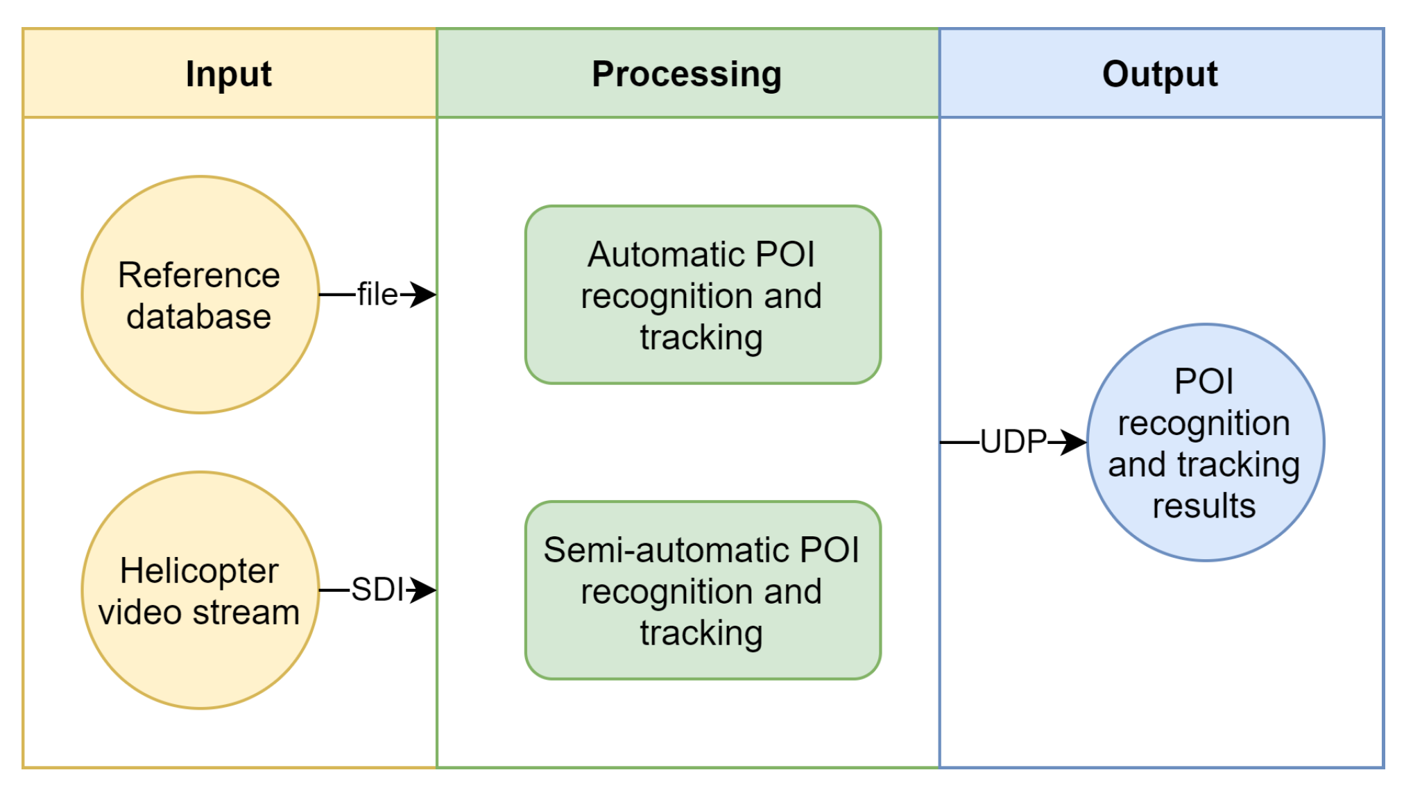
The global architecture of our solution can be conceptually divided into three main stages: input, processing, and output, as depicted in
Figure 1.
The input consists of two sources. First, a live video stream is ingested through a serial digital interface (SDI) connection, which is a standard in professional video production environments. Second, a POI reference database is available, providing necessary information for the processing stage. The details of this POI database will be further explained in
Section 3.1.
The processing component comprises two main parts: a fully automatic POI recognition and tracking pipeline and a semi-automatic user interface. The automatic pipeline employs computer vision techniques to detect, recognize, and track POIs in the live video stream. Additionally, the semi-automatic user interface allows human operators to intervene and make adjustments when needed, ensuring flexibility and reliability. These processing components will be discussed in depth in
Section 3.2 and
Section 3.3, respectively.
In the output stage, the results generated by the processing component are transmitted to a visualization engine, such as Vizrt (
https://www.vizrt.com, accessed on 22 July 2024), using the User Datagram Protocol (UDP). When both the processing and visualization servers are located within the same local network, communication between these is fast and reliable. The use of UDP allows for a decoupled architecture, where the hardware for processing and visualization can be separate.
3.1. Point of Interest Reference Database
For each race, a database is constructed by the broadcaster or broadcast service provider, which serves as a central resource for the POI recognition system and includes several key pieces of information of all POIs. First, the name of each POI is listed, which is required to transmit the correct identifier to the visualization engine when a POI is successfully recognized. Second, the world coordinates of the POI are included, enabling the system to determine which POIs are near the helicopter at any given point in time. Lastly, a small selection of reference images (up to four) for each POI is added to the database. These images play an important role in the POI recognition process, as they are used to match the contents of the current helicopter frame with the reference images.
The reference images can be sourced from various origins. A quick and low-effort method is to use high-quality images from the internet. Alternatively, pictures can be specifically captured for this purpose, ensuring a more tailored and controlled set of reference images. However, another good approach is to extract reference images directly from the helicopter footage of previous race editions. Using images from past footage results in representative references, as they will closely match the expected visual characteristics and perspective of the POIs within the new broadcast.
The process of constructing the reference database can also be automated using race course data. Online services, such as OpenStreetMap (
https://www.openstreetmap.org, accessed on 14 August 2024), can be queried to find POIs along the race course, of which a few reference images can be automatically retrieved from the internet. Although this saves preparation time before the race, this does not guarantee that all required POIs are available and are accompanied by high-quality reference images. Therefore, it is recommended to check the quality and completeness of the automatically retrieved data to ensure a smooth operation of the recognition pipeline during the live broadcast.
3.2. Automatic Point of Interest Recognition and Tracking
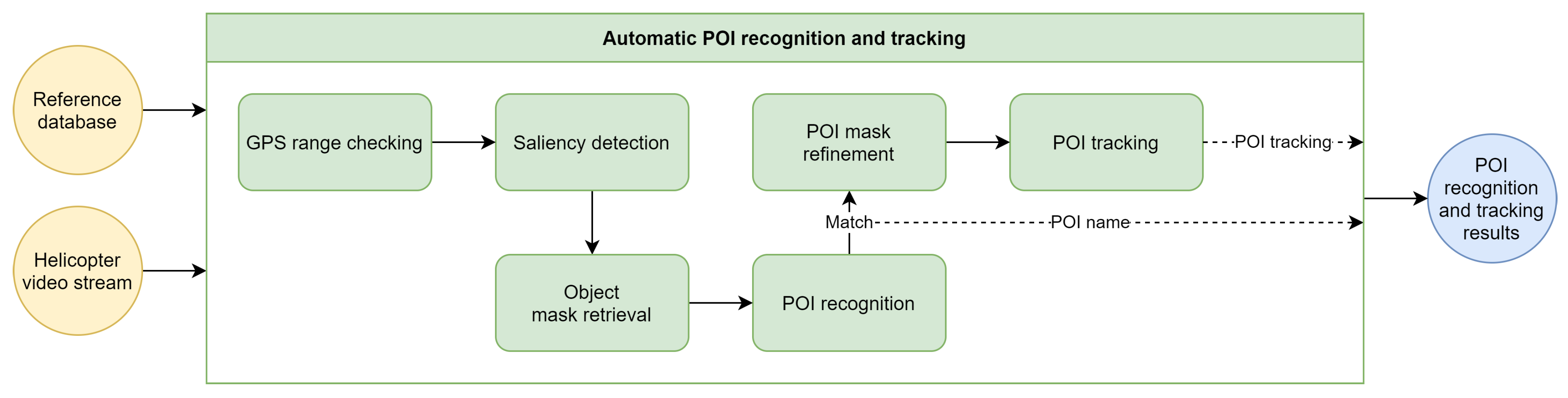
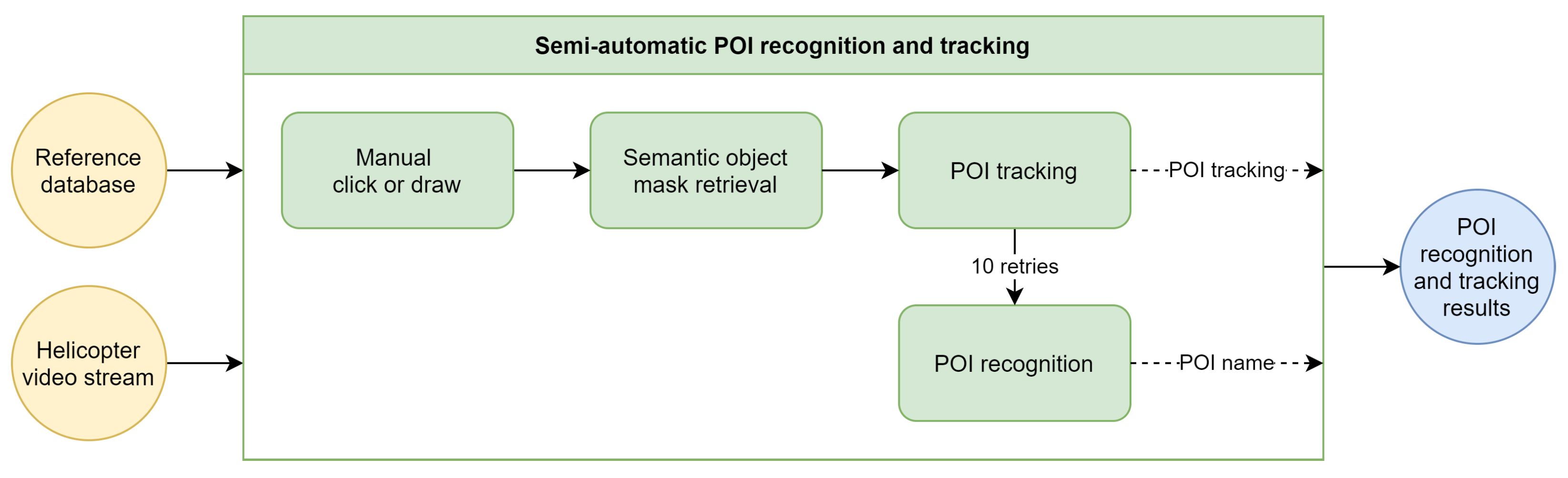
The automatic POI recognition and tracking pipeline forms the core of our methodology. As illustrated in
Figure 2, the pipeline consists of several distinct components, each fulfilling a specific role within the overall process. The following sections will provide a detailed discussion of the pipeline and its components.
3.2.1. GPS Range Checking
The automatic approach to recognize POIs begins with a check of the helicopter’s GPS position. This simple and efficient step can significantly reduce computation time and resource usage by pausing the pipeline when no POIs are in close proximity.
The haversine formula is employed to calculate the distance between the helicopter’s location and the POIs in the reference database. When no POI is detected within a 500 m range, the POI recognition pipeline is stopped and reattempted after a 1 s wait. The 500 m threshold is an adjustable parameter that can be set based on specific requirements. A shorter range will reduce computing resource utilization but increase the likelihood of missing distant POIs, for example when the helicopter’s camera is zoomed in. Conversely, a larger radius will minimize the chances of missing far-away POIs but will lead to increased resource consumption due to a more frequent execution of the detection pipeline.
3.2.2. Saliency Detection
When one or more POIs are within range of the helicopter, the next step in the pipeline, being saliency detection, is initiated. The objective of saliency detection is to identify the most visually interesting areas within an image or video. Since POIs are supposed to attract attention, they should be highlighted by the saliency detection algorithm. This approach enables the pipeline to focus on these specific areas when searching for POIs in later stages, eliminating the need to scan the entire image.
After empirically testing multiple saliency detectors, the UNISAL model developed by Droste et al. [
38] has been found to provide the best and most consistent results. One of the key advantages of the UNISAL model is its optimization for both image and video data, making it well suited for our use case. The model’s focus on video data ensures temporally consistent saliency results, which is important for maintaining coherence across frames. As the model is trained on eye-tracking data, its output closely resembles the visual attention patterns of a human observer, generating a heatmap that highlights the most visually engaging regions, as illustrated in
Figure 3. Consequently, the UNISAL model was selected for integration into our system.
3.2.3. Object Mask Retrieval
The heatmap generated in the previous step serves as the input for this stage. Here, the focus shifts to identifying the most salient object within the image. To achieve this, the most and least salient points are first located within the heatmap, which are then utilized to prompt a Segment Anything Model (SAM).
SAM is a versatile model capable of generating segmentation masks for any object in an image based on various prompts, such as bounding boxes or points. Its promptable design enables zero-shot performance on object types not encountered during training. By providing the most salient point as a positive prompt and the least salient point as a negative prompt, SAM is guided to focus on the object of interest while avoiding uninteresting areas.
The original SAM proposed by Kirillov et al. has been improved in its second version, known as SAM 2, as detailed by Ravi et al. [
39]. This updated version introduces multiple encoder sizes, which allows users to balance the model’s size with its segmentation performance. Empirical evaluations have demonstrated that SAM 2, using the largest Hiera encoder, achieves superior results in segmenting points of interest.
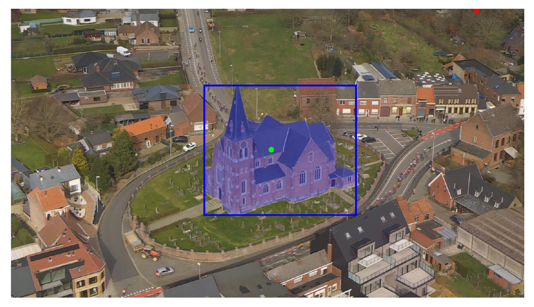
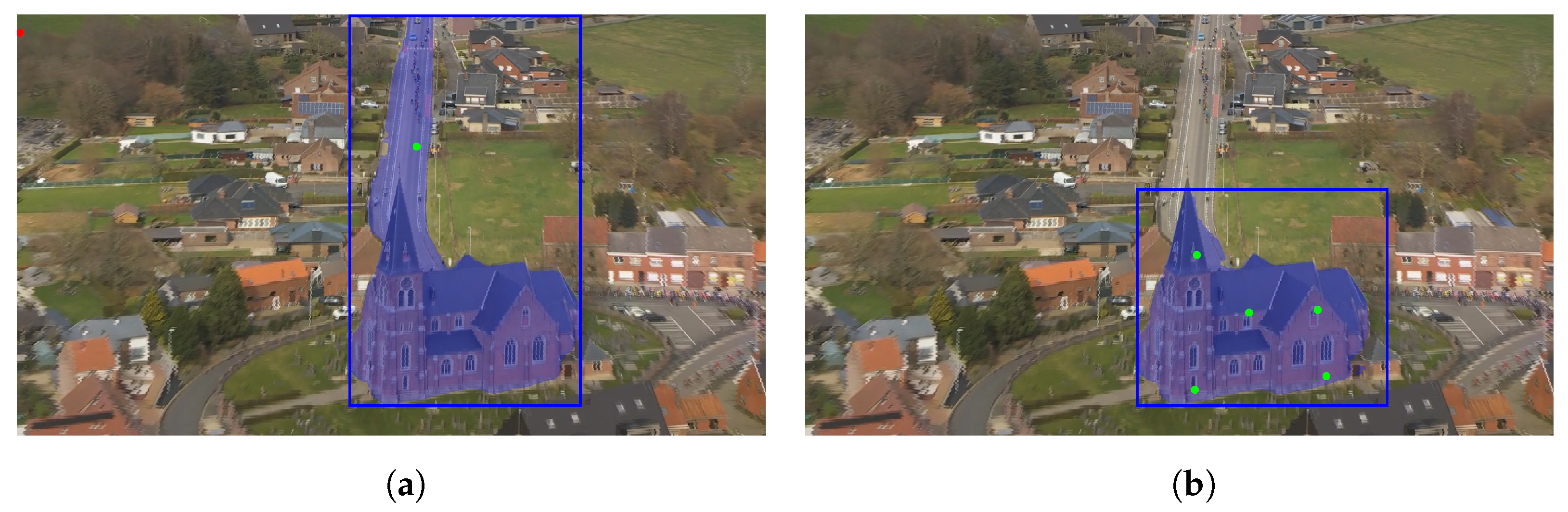
Figure 4 illustrates an example of this process. The green and red dots represent the most and least salient points, respectively. The blue mask visualizes the output of the large SAM 2, showing a well-segmented object of interest based on the provided prompt points. This demonstrates the effectiveness of the approach in accurately identifying and isolating the most salient object within the image.
3.2.4. Point of Interest Recognition
After acquiring the most salient object in the previous step, the next task is to determine whether this object is a POI and, if so, recognize the POI in question. To achieve this, the bounding box derived from the segmentation mask is used to crop the image, focusing on the most salient object. This cropped image serves as the input for the POI recognition process.
As discussed in
Section 3.1, a POI reference database is constructed, containing one or more reference images for each POI. These images are not used for training or fine-tuning a machine learning model, as the goal is to maintain a flexible and easily extensible methodology that can handle new POIs and races without requiring retraining. Instead, a keypoint matching approach is employed, enabling training-free recognition of POIs. This matching procedure consists of several steps.
First, the reference images of POIs within a 500 m radius of the helicopter’s GPS position are retrieved. This saves computational resources and ensures that the matching process focuses on relevant nearby POIs. Both the cropped image of the most salient object and the retrieved reference images are then resized to a width of 300 pixels. This size strikes a balance between maintaining a high-enough resolution for accurate feature point calculation and achieving efficient processing speeds.
Next, the keypoints and descriptors of the resized images are determined using the SuperPoint algorithm [
40]. SuperPoint is a fully convolutional neural network that extracts points and descriptors in a single forward pass, offering both speed and superior performance compared with traditional keypoint detectors and descriptors, such as SIFT. To optimize future iterations of the pipeline, the keypoint information of the reference images is automatically cached and loaded.
Finally, the SuperPoint descriptors of the salient object’s crop and reference images are matched using SuperGlue [
16], a graph neural network designed to find correspondences between two sets of sparse image features.
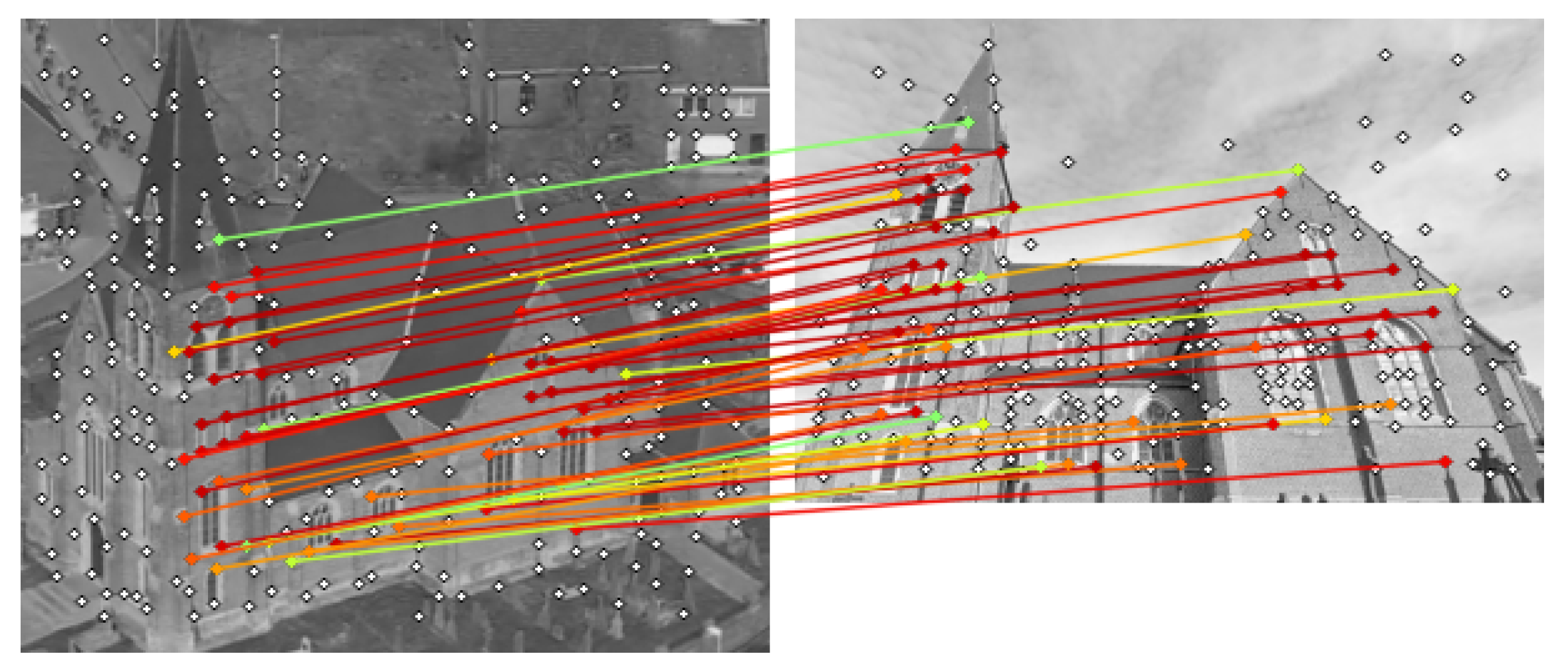
Figure 5 illustrates the keypoints and matches between the salient object crop and a reference image. Each point match is assigned a confidence score; these scores are summed to obtain a total match score per reference image. The reference image with the highest total confidence, exceeding a threshold of 10, is selected as the matched POI. If the highest total confidence falls below 10, no match is found, and the pipeline is exited, waiting for the next iteration, as shown in
Figure 5.
3.2.5. Point of Interest Mask Refinement
When a POI is recognized, it is important to ensure that the region to be tracked is as accurate as possible. As the initial POI mask and bounding box are derived from two points of the saliency detection, there are instances where the SAM output is suboptimal for tracking. To address this issue, the mask and bounding box of the POI are further refined using the available POI recognition information, thereby enhancing the subsequent tracking process.
The POI recognition step yields multiple keypoint matches between the salient object crop and the reference POI image. These keypoints are now used to reprompt SAM, resulting in an improved segmentation mask. To optimize the refinement process, not all keypoint matches are used. First, only keypoints that fall within the non-refined SAM mask are selected, eliminating keypoints of the environment, such as trees or the road, which can negatively impact the refinement. Second, five keypoints that are maximally apart from each other are chosen. This approach ensures a limited set of points that still provides good coverage over the entire POI area, as using too many prompt points can reduce the segmentation accuracy of the SAM model.
Figure 6 illustrates an example of this refinement procedure. The left image shows the SAM segmentation based solely on the saliency information, while the right image displays the refined mask incorporating the keypoint matching information. Initially, the mask incorrectly includes part of the road, which is resolved in the refinement step. By employing this refinement technique, the tracking process can be initiated with a more reliable and representative area of the POI.
3.2.6. Point of Interest Tracking
To create more visually appealing visualizations around POIs, it is important to track the location of the POI across consecutive frames. However, rerunning the entire POI recognition pipeline for every frame is not feasible due to the computational resources required, which would result in unacceptable delays for a live race broadcast. To overcome this challenge, an optical tracking algorithm is initialized after a POI is recognized, which follows the region of interest through subsequent frames. The tracking algorithm should ideally be faster than real-time to ensure smooth tracking while minimizing the delay in the broadcast chain.
Several traditional and machine learning-based trackers were compared empirically to assess their tracking quality and speed. Of those, two are chosen to integrate in the methodology. Traditional techniques, such as KCF and CSRT, are simple and offer fast tracking performance. Despite their simplicity, they have limitations in handling occlusion and large orientation changes. However, given that buildings are not frequently occluded and camera movement is often linear, they are a valid tracking possibility. Among the tested traditional algorithms, MedianFlow [
41] demonstrates accurate, smooth, and high-speed tracking results on buildings, which is why it is included in this work. Machine learning-based techniques such as Stark and Cutie perform well when tracking objects like humans and cars but struggle with tracking buildings. In contrast, the large SAM 2, which also has tracking capabilities, demonstrates very high segmentation tracking accuracy, even when the camera rotates around the POI. Therefore, next to MedianFlow, SAM 2 is provided as an option within the pipeline. Which tracker to use can be decided based on the tracking accuracy needed and the computational resources available.
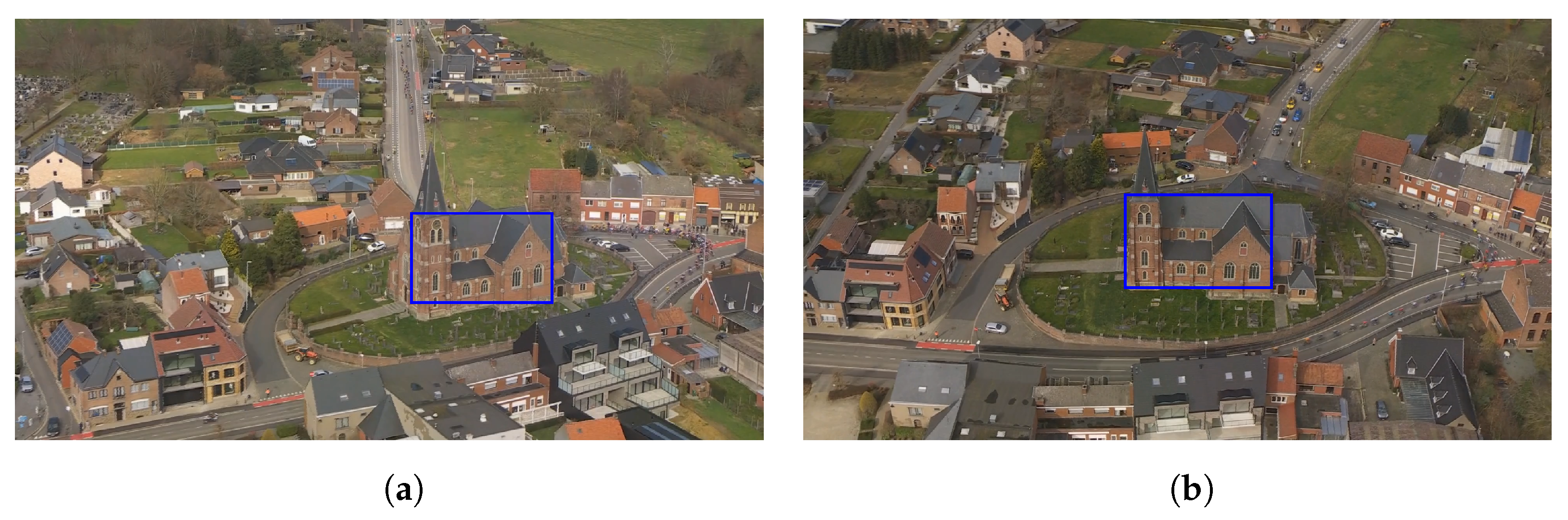
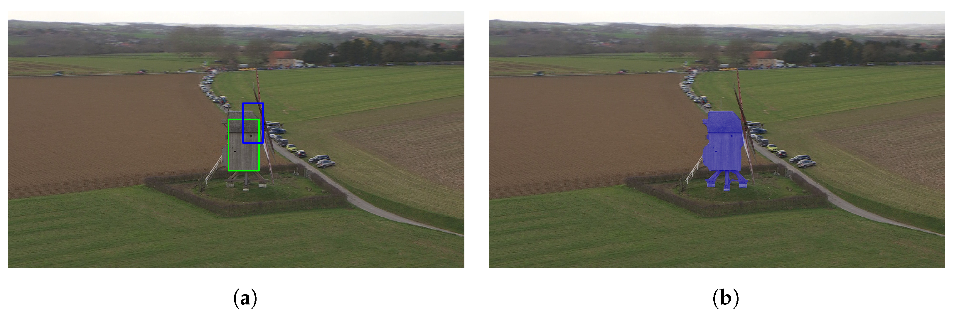
To further improve the accuracy of the MedianFlow tracker, the largest inner bounding box of the POI mask is determined and tracked. By using the inner bounding box, the tracker can better focus on the POI itself, reducing the chances of being distracted by the background.
Figure 7a shows the initial inner bounding box, whereas
Figure 7b presents the tracked bounding box 20 s later.
3.3. Semi-Automatic Point of Interest Recognition and Tracking
While the fully automatic pipeline for recognizing and tracking POIs is effective in many situations, there are instances where it may not be sufficient. For example, the automatic pipeline may fail to detect a POI or recognize it too late. Additionally, video operators may want to track an object that is not included in the reference database. To address these limitations, the proposed software provides an interface that allows for a manual selection of objects of interest. This interface displays a live helicopter video stream, allowing operators to interact directly with the footage. By clicking or drawing on any part of the stream, operators can manually initiate the POI recognition and tracking pipeline, as illustrated in
Figure 8.
The manual input from the user is used to replace the automatic detection of salient regions and points. Most of the subsequent steps in the pipeline are reused to maintain consistency, as depicted in
Figure 9. In contrast to the automatic pipeline, the semi-automatic approach reorders the POI recognition and tracking steps. After the user input is processed by the Segment Anything Model to generate a mask of the object, the tracking process is immediately initiated. This allows the broadcast operator to track objects that may not be present in the reference database. Concurrently, the POI recognition methodology is executed on a background thread. If the POI is successfully recognized, the information is passed to the visualization engine. In case of failure, the recognition process is reattempted every second, up to a maximum of 10 tries.
Note that the segmentation mask refinement step, as detailed in
Section 3.2.5, is omitted in the semi-automatic methodology. On the one hand, this decision was made to provide the user with full control over the input prompt of the SAM stage. On the other hand, it is uncertain if the selected object is in the reference database, which makes waiting for the recognition result unnecessary.
Since the semi-automatic approach reuses POI recognition and tracking components, this leads to performance levels that are comparable with, and potentially exceed, those of the fully automatic pipeline. By omitting the saliency detection component, the computational overhead and potential errors associated with it are reduced.
By incorporating a semi-automatic pipeline alongside the fully automatic one, the proposed software offers flexibility to various scenarios encountered during live broadcasts.
4. Results and Discussion
4.1. Dataset
To validate our automatic point of interest recognition and tracking pipeline, we have labeled one race, specifically the 2023 edition of Omloop Het Nieuwsblad. This Flemish race, situated around the Flemish Ardennes, includes several well-known segments such as the Muur van Geraardsbergen. Throughout the race, numerous other POIs, such as churches and windmills, are highlighted, making it a representative example for many other Belgian and European races.
For this race, a total of 10 POIs have been annotated with their names, coordinates, reference images, start times, and end times. The reference images are internet-sourced, aiming to simulate a realistic usage scenario. However, as discussed in
Section 3.1, using reference images from previous race editions might yield better recognition results. The ground truth start and end times are based on the broadcasted times of the POI in the final television broadcast, i.e., when the director switches to and from the helicopter view. Relying on the director’s broadcast decisions ensures an objective way to validate the performance of the recognition pipeline in detecting POIs in advance and ensuring that the tracking does not fail prematurely. Note that we only use the final broadcast to determine these ground truth times; the recognition and tracking itself is still performed on the raw helicopter stream. This approach was preferred to manual labeling based on the helicopter stream, which would require subjective rules for determining when a POI is in view. Additionally, the inner bounding boxes of the POIs have been annotated at the start, middle, and end of their ground truth broadcast times. These annotations allow the evaluation of the used tracking algorithm, ensuring that it remains accurate throughout the broadcast duration. The inner bounding box is used instead of the outer to allow for a more relevant evaluation of the MedianFlow tracker, which relies on the inner bounding box.
4.2. Metrics
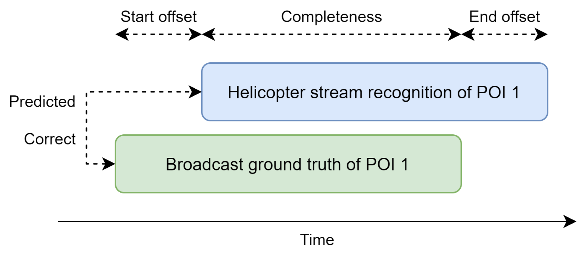
To validate the performance of the automatic point of interest recognition and tracking, we define several custom metrics that provide an individual assessment of each POI regarding the recognition correctness and timing. The metrics include the following:
Predicted: Determines whether a POI is predicted during the ground truth timeframe;
Correct: Assesses whether the POI prediction is correct;
Start offset: Measures how early or late the initial recognition occurs;
End offset: Evaluates how early or late the tracking stops;
Completeness: Quantifies the extent to which the ground truth POI shot is covered by tracking.
Figure 10 illustrates these metrics by presenting a ground truth POI time window (in green) that the automatic methodology aims to predict. In this example, both the “predicted” and “correct” metrics are true because of a correct POI prediction (in blue) within the timeframe. The “start offset” is a positive number, indicating that the prediction was delayed. Ideally, the offset should be negative, indicating that recognition occurred before the director switched to the helicopter view. Conversely, the “end offset” is positive, meaning that the tracking continued beyond the director’s switch, which is desirable in this context. The “Completeness” metric is approximately 75%, as the entire helicopter shot was not fully encompassed by POI recognition and tracking information.
Subsequently, these individual validation results are aggregated into metrics such as precision, recall, mean completeness, mean start offset, and mean end offset to provide a global overview of the system’s performance.
The validation of the tracking is conducted using the intersection over union (IoU) metric, comparing the predictions against the annotated bounding boxes at the start, middle, and end of the POI time window. By calculating the IoU at these specific points, the accuracy and consistency of the tracking can be assessed throughout the duration of the POI.
4.3. POI Recognition
The results for each point of interest, as detailed in
Appendix A, are summarized in the scores presented in
Table 1. The recall rate shows that 80% of all broadcasted POIs are correctly detected, while the precision of about 79% indicates that few misdetections are made. To elaborate on this number, all broadcasted POI detections were correct, but a few false positives were generated at times where the helicopter view was not being broadcasted. On average, each POI is recognized 15 s before the director switches to the helicopter view, demonstrating an effective and timely recognition process. When using the MedianFlow tracker, POIs are followed for approximately 6 s after the director switches away from the helicopter view. This results in a completeness of 95%, ensuring that POIs are monitored nearly throughout the entire shot. The SAM 2 tracker improves this with a mean end offset of almost 6 s longer, showing the effectiveness of this tracker. The mean completeness stays the same since the missing 5% is due to a late detection of a POI.
Examining the failure cases more closely, we observe that the
Sint-Sebastiaankerk in
Michelbeke was not recognized because the saliency model did not allocate sufficient attention to it, thereby impeding the subsequent stages of the recognition pipeline. In another instance, the first appearance of the chapel on top of the
Muur van Geraardsbergen fails at an even earlier stage of the pipeline. This failure occurred because the POI was filmed from a considerable distance, well beyond the 500 m range. As discussed in
Section 3.2.1, increasing the range would resolve this issue, but it would also result in a less resource-efficient system.
4.4. POI Tracking
The tracking performance of the system is validated at three moments during the broadcasted time window: the start, middle, and end.
Table 2 presents the mean IoU scores across all points of interest at these moments using both trackers. Additionally, the impact of the object refinement step is presented.
When using the MedianFlow tracker, the results demonstrate that the refinement improves the tracking IoU on average, with increases of 8%, 17%, and 0.6% for the start, middle, and end, respectively. However, it is also noted that tracking performance tends to decline towards the end of the POI broadcast time. The refined bounding boxes maintain better tracking performance for a longer duration compared with the non-refined boxes, as indicated by the middle scores, but ultimately, both approaches see a drop to approximately 40% by the end of the tracking period. This is due to this traditional tracker not being able to handle rotational movements well.
This limitation is clearly solved by using SAM 2 tracking. The IoU scores are not only higher overall compared with MedianFlow, they are also more consistent from the start to the end, with a refined IoU of about 65% across the board. The performance gain by the refinement step is less steep, but still decent as it helps to reduce some segmentation mistakes. Note that these are IoU scores for the inner bounding box of the tracked mask to make them comparable with the traditional tracker. This makes their results appear worse, while in practice, the tracked masks are often nearly perfect.
Appendix B provides insights in the individual tracking results for each POI, of which some of the results will be discussed in detail. For instance, the
Sint-Martinuskerk achieves high tracking scores after refinement, with most of the IoU scores over 75% for both trackers.
Figure 11a illustrates that the tracked region using the MedianFlow approach is indeed good. One outlier is the SAM 2 tracker that starts with an IoU of 61%. However, this is due to the calculation of the inner bounding box, whereas the underlying tracked mask is nearly perfect, as can be seen in
Figure 11b.
However, lower IoU scores do not necessarily indicate unusable tracking. For example, the MedianFlow tracking of the
Kartuizerpriorij starts with an IoU of 67% and drops to a score of 30%.
Figure 12a reveals that this is due to not poor tracking but rather a change in camera angle. The tracking begins when the camera is facing the POI diagonally, resulting in a smaller inner bounding box. As the helicopter turns to face the front of the POI, a larger inner bounding box becomes possible, leading to a lower IoU score, but the tracking remains relevant. Interestingly, this is one of the few failure cases of the SAM 2 tracker. It starts out perfect, but about halfway, the tracker only starts to focus on the left half of the building, leading to low IoU scores. However, the remaining segmentation mask is still decent, but not complete, as shown in
Figure 12b.
The MedianFlow tracker is not always accurate, as illustrated by the second appearance of the chapel on the
Muur van Geraardsbergen, where the tracking IoU is 0% throughout the entire live broadcast time window. This is because the POI was detected 52 s in advance, and the helicopter circled around it during this time, causing the tracker to lose the POI entirely. A similar behavior is observed with the
Vinkemolen, as shown in
Figure 13a, where the helicopter circled around the POI for 12 s before the director switched to the helicopter view. This highlights a limitation of the current tracking solution. The MedianFlow tracker performs well with linear or limited rotational movement but struggles when the helicopter flies around the POI, often losing track once the original surface disappears. In contrast, this is where the SAM 2 tracker really excels.
Figure 13b also shows the
Vinkemolen at the end of the POI timeframe. Despite the large orientation and zoom level difference, SAM 2 is still able to track the mill perfectly.
Although SAM 2 produces more accurate and robust tracking results than MedianFlow, the output of this traditional tracker is sufficient and stable for most POIs. When used live, the director could give instructions to the helicopter camera crew on which types of movement to avoid. Moreover, the semi-automatic approach allows for manual input to reset the tracking to the correct POI location, which can be performed shortly before the director switches to the helicopter view. However, if enough computational power is available, the SAM 2 tracker can be used for its superior tracking performance.
4.5. Speed Benchmark
Next to the accuracy of the POI recognition and tracking, the speed of the pipeline is equally important, especially since it is intended for use during live broadcasts. To assess the pipeline’s efficiency, the speed is benchmarked on a virtual machine with one Tesla V100 GPU, four 2.7 GHz vCPU cores, and 32 GB RAM. Live tests have shown that faster performance is achievable on dedicated hardware over this virtual machine. The average speed of the main actions in the pipeline was measured over a period of 1 h and 30 min of helicopter video footage, resulting in the timings presented in
Table 3.
As anticipated, verifying the distance between the helicopter and the points of interest to determine if any POIs are nearby is a fast operation that can significantly reduce unnecessary computations. In contrast, the POI recognition pipeline is considerably slower, requiring an average of 274 ms per check. However, since our pipeline only performs this recognition phase once per second, the achievable 4 FPS is more than sufficient. If a POI is identified, an additional 136 ms is needed to refine the POI’s region. Initializing the tracker also comes with a computational cost, which is different based on the chosen tracker. Here, it is shown that the traditional MedianFlow tracker has a higher initialization cost over the more advanced SAM 2 tracker.
Consequently, after a successful POI recognition and initialization of the tracker, the processing will, on average, lag behind the live broadcast with 851 or 721 ms for the MedianFlow or SAM 2 modus, respectively. However, with the MedianFlow tracker only taking about 13 ms per frame, i.e., processing 77 frames per second, this buffer is quickly eliminated. However, our benchmark shows that the SAM 2 tracking is not fast enough to run real-time. Still, the authors of this model report a speed of 30.2 frames per second (FPS), indicating that it is possible to run this model real-time on our video stream of 25 FPS with more powerful, dedicated hardware.
The system is designed to maintain consistent speed, even if it scales to more races and POIs. On the one hand, this is because the GPS location check is efficient, regardless of the number of POIs that need to be verified. This initial step effectively filters out unnecessary computations when no POIs are within range. On the other hand, the majority of the methodology is independent of the number of nearby POIs. The recognition step is the only component directly influenced by this. However, this rarely poses a challenge as most scenarios involve only one nearby POI, with occasional instances of up to three. The system handles these situations effectively through efficient keypoint caching.
4.6. Visualization Examples
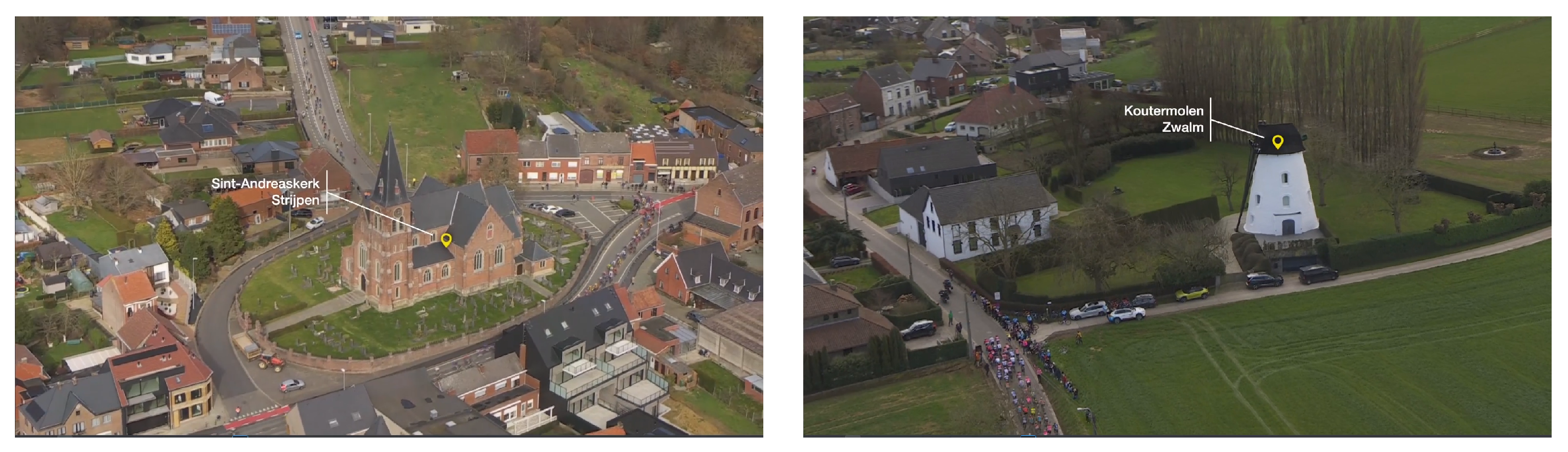
As one of the main goals of this research is to improve the viewing experience of POI overlays, we also demonstrate that the recognition and tracking data can effectively be used to generate more dynamic visualizations. Therefore, an integration is made with the Vizrt visualization engine in order to test our proposed solution end to end.
Figure 14 shows the result of this integration with two visualized examples where the name is anchored to the POI itself.
5. Additional Use Cases
Throughout the paper, a computer vision system has been introduced with the primary aim of reducing the manual workload for video editors during live broadcasts, while simultaneously making the point of interest visualizations more dynamic for viewers. Although this is the main application of the system, it also has potential for other uses, such as improving user engagement, automating reporting, and generating metadata.
Next to dynamic live visualizations, the system can also be used to generate clips of POIs for sharing through various other mediums, such as social media. This could be particularly interesting for cities looking to promote tourism to a broader audience. These clips can also incorporate tracking information for visualization purposes and can be augmented with text overlays or voice-overs using automatically generated descriptions by a large language model. Additionally, all POI clips could be compiled into a comprehensive touristic summary video, including footage that did not make the final broadcast.
Moreover, the race organization and the cities through which the race passes agree on the specific POIs to be showcased and the duration. However, currently, there is a lack of proof on whether the actual broadcasting time aligns with the agreed-upon duration. Therefore, this system could automatically generate reports detailing the POIs featured in the broadcast and their corresponding airtime, serving as evidence for the cities.
Finally, the POI detection and tracking information can be stored as metadata alongside the broadcast. This facilitates the querying and retrieval of images and video clips of these POIs in the future, which can be useful for other programs or series in need of video footage of certain POIs.
6. Conclusions and Future Work
Broadcasting a cycling race is a complex process that requires the coordinated efforts of numerous people, including cameramen, directors, and video editors. Their collective aim is to deliver a seamless live viewing experience, which requires minimal delay in processing and presenting the footage. This constraint, however, limits the complexity of visualizations, such as overlays that highlight points of interest during the race. To address these challenges and improve visualizations while reducing manual workload, a computer vision pipeline has been proposed to automatically recognize and track POIs in the helicopter stream of live race broadcasts.
The POI recognition process comprises five stages, integrating a saliency detection model with SAM to propose potential objects of interest. These are then verified using a keypoint matching approach to determine which POI they represent. This methodology has demonstrated high effectiveness, achieving a precision and recall of over 75%. Once a POI is recognized, a tracker is started to follow it through the video stream. Two tracking solutions are discussed and provided within the solution to choose from. A traditional tracker, MedianFlow, is provided due to its speed and simplicity, maintaining a mean tracking completeness of approximately 95%. Although the intersection over union scores drop from the beginning to the end of the broadcasted POI time window, the tracking remains stable and usable for live visualization. A discussed limitation of this approach is the potential loss of the POI when the camera rotates around it. To improve this, the more advanced SAM 2 tracking is also available, which achieves nearly perfect segmentation tracking results for almost all POIs, even when the camera is circling around the POI. However, this tracker requires more computing power in order to work real-time. Both tracking approaches benefit from our proposed POI region refinement step that uses the POI recognition information in order to refine the mask of the object.
Future research opportunities are available to refine this work. The current saliency-based method for proposing interesting regions could be replaced with a custom model specifically designed to detect objects like churches, windmills, and monuments, thereby increasing detection rates. For POI recognition, an embedding-based approach could enhance system scalability. Additionally, developing a custom tracking model tailored to POIs could improve robustness against rotational challenges at faster inference speeds.
In summary, this research highlights the potential of computer vision technologies to reduce human workload in live cycling race broadcasts. Additionally, it also paves the way for more engaging visualization options, enhancing the overall viewing experience of cycling races.
Author Contributions
Conceptualization, J.V., R.D., M.S., S.V.H. and S.V.; methodology, J.V.; software, J.V.; validation, J.V.; formal analysis, J.V.; investigation, J.V.; data curation, J.V.; writing—original draft preparation, J.V.; writing—review and editing, J.V., R.D., M.S., S.V.H. and S.V.; visualization, J.V.; supervision, M.S., S.V.H. and S.V.; project administration, S.V.H. and S.V.; funding acquisition, S.V.H. and S.V. All authors have read and agreed to the published version of the manuscript.
Funding
This research was funded by imec and the Flemish Government’s Department of Culture, Youth, and Media within the project called Digital Transformation Media, grant number 94186. The APC was funded by Ghent University—imec.
Data Availability Statement
The data presented in this study are available on request from the corresponding author due to confidentiality.
Acknowledgments
We acknowledge the use of GPT-4o by OpenAI for proofreading this manuscript.
Conflicts of Interest
The authors declare no conflicts of interest.
Abbreviations
The following abbreviations are used in this manuscript:
| CNN | convolutional neural network |
| FPS | frames per second |
| GPS | Global Positioning System |
| IoU | intersection over union |
| KCF | Kernelized Correlation Filters |
| POI | point of interest |
| RAM | random access memory |
| SAM | Segment Anything Model |
| SDI | serial digital interface |
| SIFT | scale-invariant feature transform |
| UDP | User Datagram Protocol |
Appendix A. Individual POI Recognition Results
| POI | Broadcasted | Predicted | Correct | Start Offset | End Offset Using MedianFlow Tracking | End Offset Using SAM 2 Tracking | Completeness |
| Sint-Martinuskerk | True | True | True | −16 s | 1.4 s | 1.6 s | 100% |
| Vinkemolen | True | True | True | −12 s | 3.3 s | 5.1 s | 100% |
| Kartuizerpriorij | True | True | True | −6 s | 8.7 s | 8.7 s | 100% |
| Sint-Ursmaruskerk | True | True | True | −17 s | 1.8 s | 2.3 s | 100% |
| Sint-Bartholomeuskerk | True | True | True | −4 s | 17 s | 22 s | 100% |
| Kapel O-L-V op de Oudenberg | True | True | True | −52 s | 7.2 s | 7.1 s | 100% |
| Sint-Jan-Baptistkerk | True | True | True | −20 s | 1 s | 2.3 s | 100% |
| Sint-Pieterskerk | True | True | True | 5 s | 6.1 s | 40 s | 62% |
| Sint-Sebastiaankerk | True | False | False | / | / | / | / |
| Kapel O-L-V op de Oudenberg | True | False | False | / | / | / | / |
| Sint-Martinuskerk | False | True | False | / | / | / | / |
| Vinkemolen | False | True | True | / | / | / | / |
| Sint-Bartholomeuskerk | False | True | True | / | / | / | / |
| Sint-Bartholomeuskerk | False | True | False | / | / | / | / |
| Kapel O-L-V op de Oudenberg | False | True | True | / | / | / | / |
| Sint-Jan-Baptistkerk | False | True | False | / | / | / | / |
/ indicates that either the POI was not recognized or has no matching ground truth.
Appendix B. Individual POI Tracking Results
| | | Mean IoU Using MedianFlow Tracking | Mean IoU Using SAM 2 Tracking |
| POI | SAM Mask | Start | Middle | End | Start | Middle | End |
| Sint-Martinuskerk | Initial | 43.3% | 44.6% | 47.6% | 52.2% | 94.9% | 91.2% |
| Refined | 80.0% | 78.5% | 74.1% | 61.2% | 95.3% | 91.2% |
| Vinkemolen | Initial | 26.5% | 15.9% | 14.0% | 60.0% | 97.7% | 91.3% |
| Refined | 25.8% | 19.4% | 3.5% | 57.9% | 97.4% | 91.3% |
| Sint-Sebastiaankerk | Initial | / | / | / | / | / | / |
| Refined | / | / | / | / | / | / |
| Kartuizerpriorij | Initial | 68.4% | 30.1% | 60.1% | 42.2% | 28.3% | 0% |
| Refined | 67.3% | 29.8% | 60.2% | 41.5% | 28.2% | 0% |
| Sint-Ursmaruskerk | Initial | 72.6% | 70.1% | 57.1% | 74.4% | 71.0% | 92.7% |
| Refined | 74.0% | 77.0% | 63.9% | 74.2% | 76.9% | 95.5% |
| Kapel O-L-V op de Oudenberg | Initial | / | / | / | / | / | / |
| Refined | / | / | / | / | / | / |
| Sint-Bartholomeuskerk | Initial | 57.1% | 55.8% | 54.5% | 59.6% | 58.7% | 56.5% |
| Refined | 66.3% | 64.6% | 59.8% | 81.9% | 78.7% | 91.4% |
| Kapel O-L-V op de Oudenberg | Initial | 0% | 0% | 0% | 62.8% | 56.1% | 60.0% |
| Refined | 0% | 0% | 0% | 62.8% | 56.1% | 60.2% |
| Sint-Jan-Baptistkerk | Initial | 71.4% | 57.4% | 58.3% | 89.0% | 85.0% | 96.1% |
| Refined | 74.1% | 60.9% | 63.6% | 88.0% | 93.0% | 95.6% |
| Sint-Pieterskerk | Initial | / | 45.5% | 23.2% | / | 0% | 0% |
| Refined | / | 44.3% | 9.2% | / | 0% | 0% |
/ indicates that the POI was not recognized.
References
- ASO. EBU Members Rack up Highest Numbers of Hours Viewed for Tour de France Since 2015. Available online: https://www.letour.fr/en/news/2022/ebu-members-rack-up-highest-numbers-of-hours-viewed-for-tour-de-france-since-2015/1308860 (accessed on 26 August 2024).
- UCI. Spectacular TV and Digital Audiences for 2023 UCI Cycling World Championships in Glasgow and across Scotland. Available online: https://www.uci.org/pressrelease/spectacular-tv-and-digital-audiences-for-2023-uci-cycling-world/3KSV2mdsYiRRoPBupy1tDT (accessed on 26 August 2024).
- Sports Video Group. Newsbridge Conquers the Limitations of AI Landmark Detection. Available online: https://www.sportsvideo.org/2023/03/21/newsbridge-conquers-the-limitations-of-ai-landmark-detection/ (accessed on 14 June 2024).
- Timmaraju, A.S.; Chatterjee, A. Monulens: Real-Time Mobile-Based Landmark Recognition. Available online: https://stacks.stanford.edu/file/druid:bf950qp8995/Timmaraju_Chatterjee.pdf (accessed on 26 August 2024).
- Razali, M.N.; Tony, E.O.N.; Ibrahim, A.A.A.; Hanapi, R.; Iswandono, Z. Landmark Recognition Model for Smart Tourism using Lightweight Deep Learning and Linear Discriminant Analysis. Int. J. Adv. Comput. Sci. Appl. 2023, 14. [Google Scholar] [CrossRef]
- Smeulders, A.; Worring, M.; Santini, S.; Gupta, A.; Jain, R. Content-based image retrieval at the end of the early years. IEEE Trans. Pattern Anal. Mach. Intell. 2000, 22, 1349–1380. [Google Scholar] [CrossRef]
- Lowe, D.G. Distinctive Image Features from Scale-Invariant Keypoints. Int. J. Comput. Vis. 2004, 60, 91–110. [Google Scholar] [CrossRef]
- Mikolajczyk, K.; Schmid, C. An Affine Invariant Interest Point Detector. In Proceedings of the Computer Vision—ECCV 2002, Copenhagen, Denmark, 28–31 May 2002; Heyden, A., Sparr, G., Nielsen, M., Johansen, P., Eds.; Springer: Berlin/Heidelberg, Germany, 2002; pp. 128–142. [Google Scholar] [CrossRef]
- Sivic, J.; Zisserman, A. Video Google: A text retrieval approach to object matching in videos. In Proceedings of the Ninth IEEE International Conference on Computer Vision, Washington, DC, USA, 13–16 October 2003; Volume 2, pp. 1470–1477. [Google Scholar] [CrossRef]
- Jégou, H.; Douze, M.; Schmid, C.; Pérez, P. Aggregating local descriptors into a compact image representation. In Proceedings of the 2010 IEEE Computer Society Conference on Computer Vision and Pattern Recognition, San Francisco, CA, USA, 13–18 June 2010; pp. 3304–3311. [Google Scholar] [CrossRef]
- Philbin, J.; Chum, O.; Isard, M.; Sivic, J.; Zisserman, A. Object retrieval with large vocabularies and fast spatial matching. In Proceedings of the 2007 IEEE Conference on Computer Vision and Pattern Recognition, Minneapolis, MN, USA, 17–22 June 2007; pp. 1–8. [Google Scholar] [CrossRef]
- Jegou, H.; Douze, M.; Schmid, C. Hamming Embedding and Weak Geometric Consistency for Large Scale Image Search. In Proceedings of the Computer Vision—ECCV 2008, Marseille, France, 12–18 October 2008; Forsyth, D., Torr, P., Zisserman, A., Eds.; Springer: Berlin/Heidelberg, Germany, 2008; pp. 304–317. [Google Scholar] [CrossRef]
- Gordo, A.; Almazán, J.; Revaud, J.; Larlus, D. End-to-End Learning of Deep Visual Representations for Image Retrieval. Int. J. Comput. Vis. 2017, 124, 237–254. [Google Scholar] [CrossRef]
- Radenović, F.; Tolias, G.; Chum, O. Fine-Tuning CNN Image Retrieval with No Human Annotation. IEEE Trans. Pattern Anal. Mach. Intell. 2019, 41, 1655–1668. [Google Scholar] [CrossRef] [PubMed]
- Noh, H.; Araujo, A.; Sim, J.; Weyand, T.; Han, B. Large-Scale Image Retrieval with Attentive Deep Local Features. In Proceedings of the 2017 IEEE International Conference on Computer Vision (ICCV), Venice, Italy, 22–29 October 2017; pp. 3476–3485. [Google Scholar] [CrossRef]
- Sarlin, P.E.; DeTone, D.; Malisiewicz, T.; Rabinovich, A. SuperGlue: Learning Feature Matching with Graph Neural Networks. In Proceedings of the 2020 IEEE/CVF Conference on Computer Vision and Pattern Recognition (CVPR), Seattle, WA, USA, 13–19 June 2020; pp. 4937–4946. [Google Scholar] [CrossRef]
- Cao, B.; Araujo, A.; Sim, J. Unifying Deep Local and Global Features for Image Search. In Proceedings of the Computer Vision—ECCV 2020, Glasgow, UK, 23–28 August 2020; Vedaldi, A., Bischof, H., Brox, T., Frahm, J.M., Eds.; Springer International Publishing: Cham, Switzerland, 2020; pp. 726–743. [Google Scholar] [CrossRef]
- Teichmann, M.; Araujo, A.; Zhu, M.; Sim, J. Detect-to-Retrieve: Efficient Regional Aggregation for Image Search. In Proceedings of the 2019 IEEE/CVF Conference on Computer Vision and Pattern Recognition (CVPR), IEEE Computer Society, Long Beach, CA, USA, 15–20 June 2019; pp. 5104–5113. [Google Scholar] [CrossRef]
- Kumar, A.; Bhowmick, S.; Jayanthi, N.; Indu, S. Improving Landmark Recognition Using Saliency Detection and Feature Classification. In Digital Techniques for Heritage Presentation and Preservation; Springer International Publishing: Cham, Switzerland, 2021; pp. 157–175. [Google Scholar] [CrossRef]
- Cheng, M.M.; Zhang, Z.; Lin, W.Y.; Torr, P. BING: Binarized Normed Gradients for Objectness Estimation at 300fps. In Proceedings of the 2014 IEEE Conference on Computer Vision and Pattern Recognition, Columbus, OH, USA, 23–28 June 2014; pp. 3286–3293. [Google Scholar] [CrossRef]
- Kirillov, A.; Mintun, E.; Ravi, N.; Mao, H.; Rolland, C.; Gustafson, L.; Xiao, T.; Whitehead, S.; Berg, A.C.; Lo, W.Y.; et al. Segment Anything. arXiv 2023, arXiv:2304.02643. [Google Scholar]
- Baker, S.; Matthews, I. Lucas-Kanade 20 Years on: A Unifying Framework. Int. J. Comput. Vis. 2004, 56, 221–255. [Google Scholar] [CrossRef]
- Fukunaga, K.; Hostetler, L. The estimation of the gradient of a density function, with applications in pattern recognition. IEEE Trans. Inf. Theory 1975, 21, 32–40. [Google Scholar] [CrossRef]
- Henriques, J.F.; Caseiro, R.; Martins, P.; Batista, J. High-Speed Tracking with Kernelized Correlation Filters. IEEE Trans. Pattern Anal. Mach. Intell. 2015, 37, 583–596. [Google Scholar] [CrossRef] [PubMed]
- Lukežič, A.; Vojíř, T.; Čehovin Zajc, L.; Matas, J.; Kristan, M. Discriminative Correlation Filter Tracker with Channel and Spatial Reliability. Int. J. Comput. Vis. 2018, 126, 671–688. [Google Scholar] [CrossRef]
- Bertinetto, L.; Valmadre, J.; Henriques, J.F.; Vedaldi, A.; Torr, P.H.S. Fully-Convolutional Siamese Networks for Object Tracking. In Proceedings of the Computer Vision—ECCV 2016 Workshops, Amsterdam, The Netherlands, 8–10 and 15–16 October 2016; Springer International Publishing: Cham, Switzerland, 2016; pp. 850–865. [Google Scholar] [CrossRef]
- Li, B.; Yan, J.; Wu, W.; Zhu, Z.; Hu, X. High Performance Visual Tracking with Siamese Region Proposal Network. In Proceedings of the 2018 IEEE/CVF Conference on Computer Vision and Pattern Recognition, Salt Lake City, UT, USA, 18–23 June 2018; pp. 8971–8980. [Google Scholar] [CrossRef]
- Xu, Y.; Wang, Z.; Li, Z.; Yuan, Y.; Yu, G. SiamFC++: Towards Robust and Accurate Visual Tracking with Target Estimation Guidelines. In Proceedings of the AAAI Conference on Artificial Intelligence, New York, NY, USA, 7–12 February 2020; Voume 34, pp. 12549–12556. [Google Scholar] [CrossRef]
- Ondrašovič, M.; Tarábek, P. Siamese Visual Object Tracking: A Survey. IEEE Access 2021, 9, 110149–110172. [Google Scholar] [CrossRef]
- Chen, X.; Yan, B.; Zhu, J.; Wang, D.; Yang, X.; Lu, H. Transformer Tracking. In Proceedings of the 2021 IEEE/CVF Conference on Computer Vision and Pattern Recognition (CVPR), Nashville, TN, USA, 20–25 June 2021; pp. 8122–8131. [Google Scholar] [CrossRef]
- Wang, J.; Song, Y.; Song, C.; Tian, H.; Zhang, S.; Sun, J. CVTrack: Combined Convolutional Neural Network and Vision Transformer Fusion Model for Visual Tracking. Sensors 2024, 24, 274. [Google Scholar] [CrossRef] [PubMed]
- Yan, B.; Peng, H.; Fu, J.; Wang, D.; Lu, H. Learning Spatio-Temporal Transformer for Visual Tracking. In Proceedings of the 2021 IEEE/CVF International Conference on Computer Vision (ICCV), Montreal, QC, Canada, 10–17 October 2021; pp. 10428–10437. [Google Scholar] [CrossRef]
- Cui, Y.; Jiang, C.; Wu, G.; Wang, L. MixFormer: End-to-End Tracking with Iterative Mixed Attention. IEEE Trans. Pattern Anal. Mach. Intell. 2024, 46, 4129–4146. [Google Scholar] [CrossRef] [PubMed]
- Wang, Q.; Zhang, L.; Bertinetto, L.; Hu, W.; Torr, P.H. Fast Online Object Tracking and Segmentation: A Unifying Approach. In Proceedings of the 2019 IEEE/CVF Conference on Computer Vision and Pattern Recognition (CVPR), Long Beach, CA, USA, 15–20 June 2019; pp. 1328–1338. [Google Scholar] [CrossRef]
- Cheng, H.K.; Oh, S.W.; Price, B.; Lee, J.Y.; Schwing, A. Putting the Object Back into Video Object Segmentation. arXiv 2024, arXiv:2310.12982. [Google Scholar]
- Yang, J.; Gao, M.; Li, Z.; Gao, S.; Wang, F.; Zheng, F. Track Anything: Segment Anything Meets Videos. arXiv 2023, arXiv:2304.11968. [Google Scholar]
- Cheng, Y.; Li, L.; Xu, Y.; Li, X.; Yang, Z.; Wang, W.; Yang, Y. Segment and Track Anything. arXiv 2023, arXiv:2305.06558. [Google Scholar]
- Droste, R.; Jiao, J.; Noble, J.A. Unified Image and Video Saliency Modeling. In Proceedings of the 16th European Conference on Computer Vision (ECCV), Glasgow, UK, 23–28 August 2020; Volume 12350. [Google Scholar] [CrossRef]
- Ravi, N.; Gabeur, V.; Hu, Y.T.; Hu, R.; Ryali, C.; Ma, T.; Khedr, H.; Rädle, R.; Rolland, C.; Gustafson, L.; et al. SAM 2: Segment Anything in Images and Videos. arXiv 2024, arXiv:2408.00714. [Google Scholar]
- DeTone, D.; Malisiewicz, T.; Rabinovich, A. SuperPoint: Self-Supervised Interest Point Detection and Description. In Proceedings of the 2018 IEEE/CVF Conference on Computer Vision and Pattern Recognition Workshops (CVPRW), Salt Lake City, UT, USA, 18–22 June 2018; pp. 224–236. [Google Scholar] [CrossRef]
- Kalal, Z.; Mikolajczyk, K.; Matas, J. Tracking-Learning-Detection. IEEE Trans. Pattern Anal. Mach. Intell. 2012, 34, 1409–1422. [Google Scholar] [CrossRef] [PubMed]
Figure 1.
High-level overview of the complete point of interest recognition and tracking methodology.
Figure 1.
High-level overview of the complete point of interest recognition and tracking methodology.
Figure 2.
Overview of the automatic point of interest recognition and tracking methodology.
Figure 2.
Overview of the automatic point of interest recognition and tracking methodology.
Figure 3.
Example visualization of the saliency heatmap predicted by the UNISAL model.
Figure 3.
Example visualization of the saliency heatmap predicted by the UNISAL model.
Figure 4.
Example visualization of the predicted mask and derived bounding box by the Segment Anything Model (SAM) when prompted with the most and least salient point.
Figure 4.
Example visualization of the predicted mask and derived bounding box by the Segment Anything Model (SAM) when prompted with the most and least salient point.
Figure 5.
Example visualization of the keypoints and matches generated by the SuperGlue model. The left image is the helicopter video frame cropped to the proposed region by the saliency and SAM model, whereas the right image shows the reference. The color of the line indicates the confidence of the match with red being the strongest.
Figure 6.
Example visualization of (a) the predicted SAM mask before refinement and (b) the predicted SAM mask after refinement using the POI recognition keypoint information.
Figure 6.
Example visualization of (a) the predicted SAM mask before refinement and (b) the predicted SAM mask after refinement using the POI recognition keypoint information.
Figure 7.
Example visualization of the tracked inner bounding box using the MedianFlow tracker with (a,b) being 20 s apart from each other.
Figure 7.
Example visualization of the tracked inner bounding box using the MedianFlow tracker with (a,b) being 20 s apart from each other.
Figure 8.
Visualization of the manual input (yellow) for the recognition and tracking pipeline by drawing on the live broadcast.
Figure 8.
Visualization of the manual input (yellow) for the recognition and tracking pipeline by drawing on the live broadcast.
Figure 9.
Overview of the semi-automatic point of interest recognition and tracking methodology.
Figure 9.
Overview of the semi-automatic point of interest recognition and tracking methodology.
Figure 10.
Graphical overview of the calculated metrics per POI.
Figure 10.
Graphical overview of the calculated metrics per POI.
Figure 11.
Visualizations of the tracking results of the Sint-Martinuskerk at the end of the POI time window using (a) the MedianFlow tracker (green box = ground truth, blue box = prediction) and (b) the SAM 2 tracker (blue mask = prediction). Both trackers perform very well on this POI.
Figure 11.
Visualizations of the tracking results of the Sint-Martinuskerk at the end of the POI time window using (a) the MedianFlow tracker (green box = ground truth, blue box = prediction) and (b) the SAM 2 tracker (blue mask = prediction). Both trackers perform very well on this POI.
Figure 12.
Visualization of the tracking results of the Kartuizerpriorij at the middle of the broadcast time window using (a) the MedianFlow tracker (green box = ground truth, blue box = prediction) and (b) the SAM 2 tracker (blue mask = prediction). The IoU of the MedianFlow tracker seems low, but the resulting tracking is good and stable. SAM 2 loses track of the right side of the building, which also leads to lower IoU scores.
Figure 13.
Visualization of the tracking results of the Vinkemolen at the middle of the broadcast time window using (a) the MedianFlow tracker (green box = ground truth, blue box = prediction) and (b) the SAM 2 tracker (blue mask = prediction). MedianFlow lost track of the windmill because the helicopter was rotating around it. In contrast, SAM 2 handles this rotation perfectly.
Figure 14.
Example visualizations generated by Vizrt based on the POI recognition and tracking data, demonstrating more dynamic POI overlays.
Figure 14.
Example visualizations generated by Vizrt based on the POI recognition and tracking data, demonstrating more dynamic POI overlays.
Table 1.
POI recognition and tracking results when using either the MedianFlow or SAM 2 tracker. The precision, recall, and mean start offset are purely based on the recognition phase, so these results cannot differ between trackers.
Table 1.
POI recognition and tracking results when using either the MedianFlow or SAM 2 tracker. The precision, recall, and mean start offset are purely based on the recognition phase, so these results cannot differ between trackers.
| Metric | Using MedianFlow
Tracking | Using SAM 2 Tracking |
|---|
| Precision | 78.6% |
| Recall | 80% |
| Mean start offset | −15.3 s |
| Mean end offset | 5.8 s | 11.1 s |
| Mean completeness | 95.3% | 95.3% |
Table 2.
POI tracking results when using either the MedianFlow or SAM 2 tracker. For MedianFlow, the IoU between the ground truth and tracked inner bounding box is calculated. For SAM 2, the inner bounding box is first derived based on the tracked mask in order to provide IoU results that are comparable with the other tracker. Next, IoU scores for the tracking based on both the initial and refined mask are given to evaluate the effectiveness of this processing step.
| | Mean IoU Using MedianFlow Tracking | Mean IoU Using SAM 2 Tracking |
|---|
| SAM Mask | Start | Middle | End | Start | Middle | End |
|---|
| Initial | 48.5% | 39.9% | 39.4% | 62.9% | 61.5% | 61.0% |
| Refined | 55.4% | 46.8% | 41.8% | 66.8% | 65.7% | 65.6% |
Table 3.
Speed benchmark results when using either the MedianFlow or SAM 2 tracker. The first 5 steps are equal for both since they are independent of the used tracker.
Table 3.
Speed benchmark results when using either the MedianFlow or SAM 2 tracker. The first 5 steps are equal for both since they are independent of the used tracker.
| Functionality | Using MedianFlow Tracking | Using SAM 2 Tracking |
|---|
| GPS range checking | 0.11 ms ± 0.02 ≈ 9090 FPS |
| Saliency detection | 91 ms ± 60 ≈ 11 FPS |
| Object mask retrieval | 61 ms ± 5 ≈ 16 FPS |
| POI recognition | 122 ms ± 41 ≈ 8 FPS |
| Total of recognition phase | 274 ms ± 106 ≈ 4 FPS |
| POI mask refinement | 136 ms ± 87 ≈ 7 FPS |
| Tracker initialization | 441 ms ± 418 ≈ 2 FPS | 311 ms ± 33 ≈ 3 FPS |
| Total of tracking preparation phase | 577 ms ± 505 ≈ 2 FPS | 447 ms ± 120 ≈ 2 FPS |
| Tracking step | 13 ms ± 1 ≈ 77 FPS | 364 ms ± 36 ≈ 3 FPS |
| Disclaimer/Publisher’s Note: The statements, opinions and data contained in all publications are solely those of the individual author(s) and contributor(s) and not of MDPI and/or the editor(s). MDPI and/or the editor(s) disclaim responsibility for any injury to people or property resulting from any ideas, methods, instructions or products referred to in the content. |
© 2024 by the authors. Licensee MDPI, Basel, Switzerland. This article is an open access article distributed under the terms and conditions of the Creative Commons Attribution (CC BY) license (https://creativecommons.org/licenses/by/4.0/).


