Abstract
The pile-bucket composite foundation represents an innovative foundation form that surpasses the horizontal bearing performance of both single bucket-shaped foundations and pile foundations. The intricate interplay between piles and buckets introduces the complexity of the factors influencing the bearing performance of composite foundations under horizontal loads. In this paper, the indoor model tests were conducted to investigate the effects of relative density and pile-to-barrel diameter ratio on the horizontal bearing capacity and surrounding soil pressure of the pile-bucket composite foundation. A sensitivity analysis on the bearing characteristics of the pile-bucket foundation was performed using ABAQUS/CAE 2020 software. The results reveal a consistent variation in load–displacement curves across diverse diameter ratios of piles to buckets. The pile-bucket diameter ratio significantly impacts the horizontal bearing characteristics of the composite foundation. Reducing the pile-bucket diameter ratio improves the horizontal bearing capacity of the composite foundation. When the diameter ratio of piles to buckets diminishes to ≤0.317, the influence of this ratio on bearing performance becomes markedly pronounced. The displacement range of the surface soil decreases with an increase in relative density, while the influence depth of the surrounding soil of the composite foundation significantly decreases as the pile-to-barrel diameter ratio decreases.
1. Introduction
Compared to onshore wind energy, offshore wind power exhibits higher energy efficiency coupled with advantages such as higher wind speeds, reduced dust, and extended turbine lifespan. Offshore wind turbines are subjected to long-term effects of ocean waves and horizontal wind loads in operation. Consequently, horizontal loads represent the predominant controlling factor in the design of wind power foundations.
At present, offshore wind farms in China are primarily situated in coastal waters, with relatively modest installed capacities. However, as offshore wind power gradually expands into deeper waters and higher power ratings, there is an escalating demand for increased load-bearing capacity in wind power foundations. In response to these requirements, various novel foundation designs suitable for offshore wind power were proposed. Faizi et al. [1] proposed that the composite three-bucket foundation combined with a circular plate can effectively improve the foundation’s anti-overturning ability and thus improve the overall bearing capacity of the structure; Zhang et al. [2] employed a horizontal monotonic loading model test on hollow conical foundations under medium-coarse sand conditions and explored the impacts of foundation dimensions and loading height on the horizontal bearing capacity, as well as the distribution patterns of soil pressure; and Bayton et al. [3] experimentally determined that the deflection and bending moments of large-diameter piles calculated using API specification were lower than the measured values. Liu et al. [4] focused on the influence of pile-bucket structure dimensions and penetration depth on foundation-bearing capacity and deformation by a three-dimensional finite element model. The results indicated that increasing the depth of penetration of both the foundation pile and bucket effectively enhanced the structure resistance of overturning. Wang et al. [5] highlighted that, relative to sandy soil, the enhancement in the overall bearing capacity of the structure is more pronounced in soft clay with a pile-bucket composite foundation in a comparative study involving a single-pile foundation, bucket-shaped foundation, and pile-bucket composite foundation; Sun et al. [6] asserted that the diameter of the bucket has the greatest impact on the load-bearing performance of the pile-bucket composite foundation with an increase in bucket diameter proving to be an effective means of enhancing structural load-bearing capacity; Huang et al. [7] studied the sharing of the load by different parts of the foundation and the failure mode under vertical loading, concluding that composite foundation can effectively improve load-bearing capacity; Zhou et al. [8] proposed a theoretical formula for the horizontal load-bearing capacity of a pile-bucket composite foundation considering varying numbers of piles based on the ultimate equilibrium method; Wang et al. [9] studied the load-bearing capacity degradation patterns of the pile-bucket composite foundations under static and cyclic loading, indicating that, compared to bucket height, an increase in bucket diameter more significantly improved the load-bearing capacity of the foundation; Chen et al. [10] investigated the response of the pile-bucket composite foundation under static and dynamic loads, demonstrating that the composite foundation can reduce the depth of the pile penetration and effectively decrease the rotation angle and horizontal displacement of the foundation; and Liu et al. [11] conducted modal analysis on a pile-bucket composite foundation with ABAQUS software and highlighted optimal pile-bucket diameter ratios and bucket skirt height. Chen et al. [12] found that, compared with single-pile foundations, the pile-bucket composite foundation significantly reduced the seismic response of offshore wind turbines (OWTs). In summary, composite foundations integrating pile and bucket effectively enhanced the load-bearing capacity of the foundations.
Li et al. [13] studied the influence of grouting connections on the load-bearing characteristics of pile-bucket composite foundations. Wang et al. [5] and Li et al. [14] explored the impact of mixed foundation on horizontal load-bearing capacity through model tests, asserting that a pile-bucket composite foundation significantly improved lateral forces and enhanced the mobilization efficiency of shallow soil resistance.
Conducting horizontal monotonic loading model tests, this study investigates the horizontal load-bearing capacity characteristics, cumulative deformation patterns, and alterations in the surrounding soil of pile-bucket composite foundations in sand. By employing a bespoke horizontal loading apparatus and implementing PIV technology, this study achieves visual insights into the interactive dynamics at the foundation–soil interface under load conditions. This approach not only contributes empirical insights into the horizontal bearing behavior of pile-bucket composite foundations but also furnishes theoretical guidance crucial for the design optimization of such foundations.
2. Model Test
The model test equipment is shown in Figure 1, comprising primarily a horizontal loading system, a data and image acquisition system, a model box, and a model pile-bucket composite foundation.
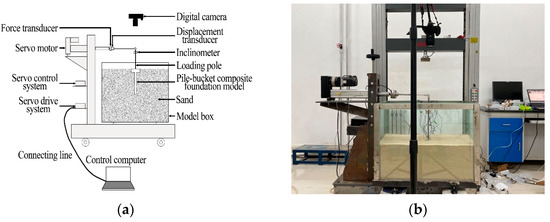
Figure 1.
Test device diagram. (a) Horizontal load test device schematic diagram; (b) Image acquisition system.
2.1. Horizontal Loading System and Data Acquisition
The loading device utilizes a self-developed displacement-controlled horizontal loading system, which is principally composed of a servo motor, servo control system, servo drive system, gearbox, force sensor, and displacement sensor. A precision electronic inclinometer with an accuracy of 0.01° is affixed to the loading rod to meticulously record alterations in the foundation’s horizontal rotation angle. This study specifies that the side of the foundation aligned with the loading direction is the front side, while the opposite is designated as the rear side. Soil pressure gauges are strategically positioned based on the foundation height (at depths of 0, 30 (bucket), 30 (pile), 115, and 200 mm). Five soil pressure gauges are installed both in the front and rear sections, each calibrated with a range of 10 kPa, facilitating the measurement of variations in soil pressure around the foundation throughout the loading process, as illustrated in Figure 2.
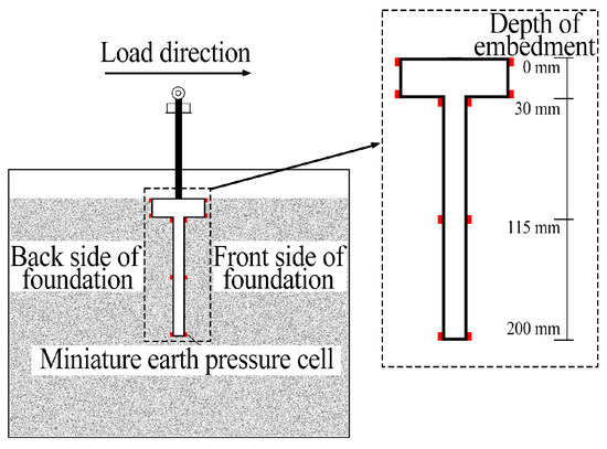
Figure 2.
Arrangement of earth pressure gauge.
2.2. Model Box and Model Pile
The dimensions of the model box are 650 mm × 450 mm × 800 mm, constructed from organic glass. In offshore wind power foundations, large-diameter single-pile foundations are commonly employed, featuring steel piles with diameters ranging from 3.5 m to 5 m. In this study, the external diameter of the pile in the pile-bucket composite foundation is set at 5 m, with the pile embedded to a depth of 40 m. The external diameters of the bucket are specified as 10 m, 12 m, and 14 m, with a bucket embedding depth of 6 m. To maintain scale fidelity, the model dimensions are downscaled at a ratio of 1:200 based on these foundation dimensions. The model pile has a designated embedded depth (l) of 200 mm, a wall thickness (t) of 2 mm, and an external diameter (d) of 25 mm. Meanwhile, the model bucket exhibits an embedded depth (L) of 30 mm, an external diameter (D) of 50 mm, 60 mm, or 70 mm, and a wall thickness (T) of 2 mm. The material chosen for the model is Q235 steel with a density of 7.85 g/cm3, an elastic modulus of 200 GPa, and Poisson’s ratio of 0.25. The central segment of the foundation incorporates a fixed end to accommodate the loading rod, secured through bolts. At the apex of the loading rod, a Y-shaped joint interfaces with the loading device, ensuring a structurally sound connection.
2.3. Test Sand
The experimental sand employed in this study is the Fujian Standard Sand. To investigate the deformation mechanisms of the pile-bucket composite foundation in soils with varying densities, model tests were conducted in loose sand, medium-density sand, and dense sand states. The specific physical properties of sand are shown in Table 1. Model samples were prepared with the rainfall method. For the preparation of loose sand, the falling height was controlled and the sand was leveled in layers. In the case of medium-density sand, compaction was performed at intervals of 5 cm for each layer. For dense sand preparation, compaction was performed at intervals of 3 cm for each layer. Following each experiment, soil samples were collected to measure the relative density, ensuring comparability across the various test groups.

Table 1.
Physical properties of soil.
2.4. Data and Image Acquisition System
Displacement sensors were utilized to quantify the displacement of the loading point throughout the experiment and a force sensor was employed to gauge the loading applied to the loading point. The software interface facilitated the display of test speed and time and enabled the generation of a fluctuation curve depicting the relationship between load, displacement, and time. Image acquisition was performed using a Canon EOS 850D camera, boasting a resolution of 3840 px × 2160 px at 24 frames/s.
2.5. Test Scheme
The experimental tests were conducted using three different bucket diameters within varying states of loose sand, medium-density sand, and dense sand. To guarantee comparability, rigorous control over the experiment conditions was imperative. In each instance, the sand within the model box was excavated and the foundation along with miniature soil pressure gauges were meticulously embedded at predetermined positions. Subsequently, the sand was systematically backfilled in layers and compacted to ensure uniform relative density levels across all experiments. Upon reaching the specified height, the surface was leveled and a PIV measurement system was established at the designated location.
In this experiment, an initial full-scale test was undertaken to subject model foundations to horizontal monotonic loading, incorporating three different pile-bucket diameter ratios (d/D = 0.357, 0.417, 0.5). Displacement-controlled loading was applied at a loading rate of 2 mm/min. Before the experiment, the displacement sensor and force sensor were zeroed and the data from the soil pressure gauge and electronic level were validated and recorded. Subsequently, the load was applied simultaneously with the PIV measurement system, which monitored the deformation of the surrounding soil at the top of the foundation.
A half-scale test was then performed under identical conditions, with the PIV measurement system used to monitor the deformation of the surrounding soil adjacent to the foundation. Each experimental condition iterated a minimum of three times to ensure the reliability and comparability of the experimental results.
3. Analysis of Horizontal Bearing Characteristics
3.1. Analysis of Horizontal Bearing Performance under Different Compactness
The experiment conducted horizontal monotonic loading tests on pile-bucket composite foundations with three different diameter ratios and analyzed the effect of different sand compactness levels on the horizontal load-bearing performance of such foundations.
As depicted in Figure 3, the variation trend of the composite foundation curve under three distinct sand compactness conditions which were loose sand, medium-density sand, and dense sand. The curves can be segmented into two stages: elastic deformation and elastoplastic deformation. In the initial stage of load application, the displacement at the loading point exhibited linear growth with relatively minor increments, indicative of the soil being in a state of linear elastic deformation. With increasing load, the displacement exhibited nonlinear growth and the increment in displacement gradually escalated, indicating the translation of the soil into an elastoplastic deformation stage.
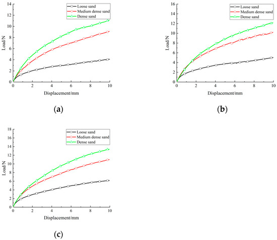
Figure 3.
Load–displacement relationship curves under different compactness. (a) Pile-bucket diameter ratio d/D = 0.5; (b) Pile-bucket diameter ratio d/D = 0.417; (c) Pile-bucket diameter ratio d/D = 0.357.
Figure 4 illustrates the relationship between horizontal load and pile head rotation. The pile head rotation of 0.5° corresponds to the horizontal ultimate bearing capacity Fu [15], with specific values detailed in Table 2. Compared to the state of medium-density sand, the horizontal ultimate bearing capacity of the composite foundation decreased by approximately 40~50% in the loose sand state. Conversely, in the dense sand state, the horizontal ultimate bearing capacity of the composite foundation registered an increase of 10~30%.
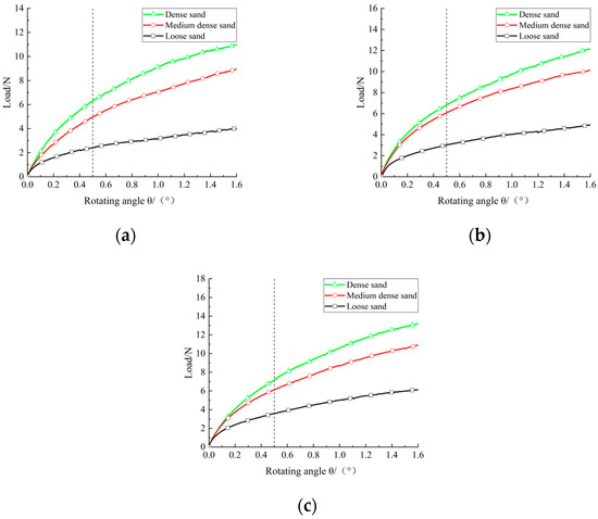
Figure 4.
Load-rotation relationship curves under different compactness. (a) Pile-bucket diameter ratio d/D = 0.5; (b) Pile-bucket diameter ratio d/D = 0.417; (c) Pile-bucket diameter ratio d/D = 0.357.
Table 2.
Horizontal ultimate bearing capacity.
3.2. Soil Pressure Distribution Laws
Figure 5, Figure 6 and Figure 7 illustrate the variations in soil pressure increments at different depths when the composite foundation with a pile-bucket diameter ratio of d/D = 0.5 reaches its ultimate load under diverse relative density conditions. In instances where the soil pressure increment at a measurement point registers as negative, it indicates that the foundation is subject to active soil pressure; conversely, a positive soil pressure increment indicates passive soil pressure exerted on the foundation.
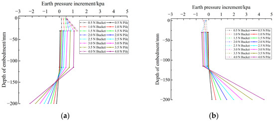
Figure 5.
Soil pressure increment distribution of loose sand pile-bucket diameter ratio of 0.5. (a) Front side of the foundation; (b) Back side of the foundation.
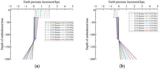
Figure 6.
Soil pressure increment distribution of a medium dense sand pile-bucket diameter ratio of 0.5. (a) Front side of the foundation; (b) Back side of the foundation.
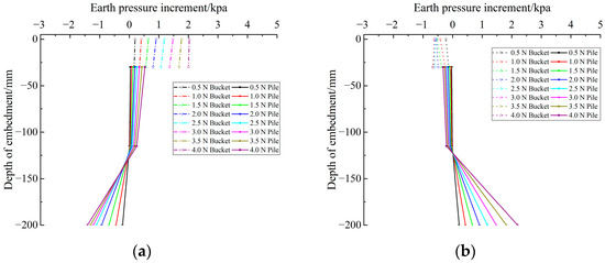
Figure 7.
Soil pressure increment distribution of a dense sand pile-bucket diameter ratio of 0.5. (a) Front side of the foundation; (b) Back side of the foundation.
As shown in Figure 5a, the soil pressure increment at the front of the upper bucket foundation consistently maintains a positive value, indicating that this measurement point consistently resides in the passive soil pressure zone. With an incremental load, the soil pressure increment at a depth of 0 mm decreases gradually, while the soil pressure increment at a depth of 30 mm increases. Similar trends are observed at depths of 30 mm and 115 mm for the lower pile foundation. At a depth of 200 mm, the soil pressure increment initially decreases with the applied load, subsequently exhibiting an increased trend. The behavior could be attributed to the surface sand of the composite foundation being loose in the loose sand condition, limiting its capacity to offer substantial resistance as the load intensifies. In contrast, the lower soil body, compacted by the foundation, results in a denser arrangement of soil particles, affording greater soil resistance. Notably, the soil pressure increment at a depth of 30 mm for the upper bucket foundation significantly surpasses that at the pile foundation, indicating superior resistance of the bucket foundation to horizontal loads and a greater share of the horizontal load-bearing capacity in the composite foundation. In Figure 5b, the soil pressure increments at the back of the foundation at depths of 0 mm, 30 mm, and 115 mm all exhibit negative values, indicating that these measurement points consistently fall within the active soil pressure zone. Meanwhile, the soil pressure increment at a depth of 200 mm is positive and gradually increases with increasing load.
Figure 6 and Figure 7 correspond to the states of a medium dense sand state and dense sand state, respectively, showing the variations in soil pressure increments at various measurement points. It can be observed that with an increase in soil density, the soil pressure increments at the measurement points on the bucket foundation significantly increase, while those on the pile foundation decrease. It implies that as soil density rises, the bucket foundation predominantly shoulders the responsibility of resisting horizontal loads in the composite foundation.
Figure 8 and Figure 9 show the variations in soil pressure increments with depth at diverse measurement points for composite foundations with pile-bucket diameter ratios of d/D = 0.417 and 0.357, respectively, under loose sand conditions. A comparative analysis with Figure 5 reveals that as the diameter of the bucket foundation increases, the soil pressure increment at the 30 mm measurement point of the bucket foundation increases under the same load, while the soil pressure increment at the 200 mm measurement point of the pile foundation decreases. It indicates that under the same sand relative density conditions, increasing the diameter of the bucket foundation in the composite foundation has a significant effect on resisting horizontal loads.
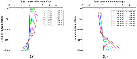
Figure 8.
Soil pressure increment distribution of a loose sand pile-bucket diameter ratio of 0.417. (a) Front side of the foundation; (b) Back side of the foundation.
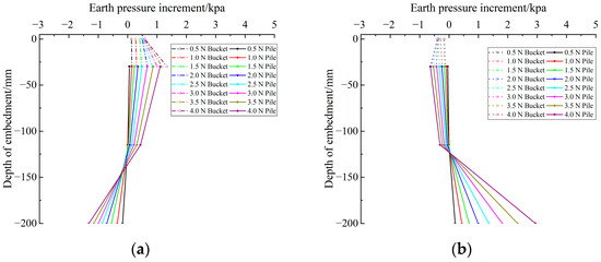
Figure 9.
Soil pressure increment distribution of a loose sand pile-bucket diameter ratio of 0.357. (a) Front side of the foundation; (b) Back side of the foundation.
4. Finite Element Calculation Model
Through a comparative analysis of experimental results under varying relative density conditions, the horizontal bearing characteristics of pile-bucket composite foundations have been investigated. Nevertheless, further examination is warranted regarding the impact of the bucket diameter on the composite foundation in practical engineering. In this section, numerical simulation results are compared with experimental results to validate the rationality and reliability of the numerical simulation. The investigation extends to exploring the influence of different bucket diameters on the bearing characteristics of composite foundations featuring both piles and a bucket foundation, achieved by incorporating various pile-bucket diameter ratios in the numerical simulations.
4.1. Establishment and Verification of a Model
A three-dimensional numerical model was constructed with ABAQUS finite element software, maintaining identical dimensions to those employed in the indoor model test. The schematic representation of the three-dimensional numerical model and its mesh division are depicted in Figure 10. The soil was characterized using the Mohr–Coulomb constitutive model, while the composite foundation adopted the elastic constitutive model. The pile–soil contact surface incorporated a friction model [16]. In the friction model, the normal behavior adopted “hard” contact and the tangential behavior followed the penalty friction formula. The parameter settings aligned with those of the model test. The detailed parameter settings are shown in Table 3. The lateral displacement was constrained throughout the numerical model and both lateral and vertical displacements were constrained at the bottom. The top featured a free boundary condition. The numerical simulation underwent an initial ground stress balance before applying a displacement load of 2 mm/min to the pile top.
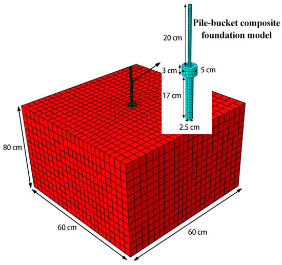
Figure 10.
Numerical model and grid distribution.
Table 3.
Numerical simulation parameters.
To affirm the reliability and validity of the numerical model, the numerical simulation results were compared with the load–displacement curves of the model test, as shown in Figure 11. The load–displacement curve generated by the numerical simulation exhibited a consistent pattern with the model test, demonstrating a noteworthy alignment between the two curves. The ultimate bearing capacities of the composite foundation with pile-bucket diameter ratios of 0.5, 0.417, and 0.357 obtained from the model tests under dense sand conditions were 6.24 N, 6.89 N, and 7.32 N, respectively. The relative errors compared to the model test results were 1.1%, 1%, and 2.1%, respectively. Therefore, it is verified that the above numerical model is reliable.
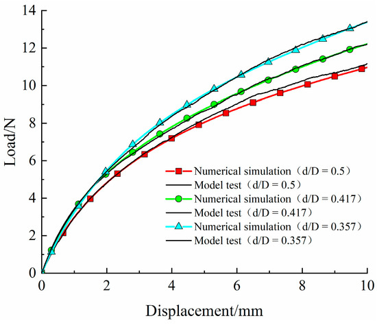
Figure 11.
Comparison of numerical simulation and model test load–displacement results.
4.2. Analysis of the Influence of the Pile-Bucket Diameter Ratio on the Bearing Capacity of Composite Foundation
Figure 12 illustrates the correlation between horizontal load and displacement for various pile-bucket diameter ratios under dense sand conditions, comparing both the model test and numerical simulation.
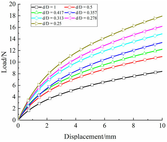
Figure 12.
Load–displacement relationship under different pile-bucket diameter ratios.
Inspection of Figure 12 reveals that under different pile-bucket diameter ratios, the initial horizontal displacement of the composite foundation increases linearly with increasing load. Once a critical load is attained, the displacement increases significantly. For a given load, the larger pile-bucket diameter ratios exhibit a higher rate of displacement increment compared to their smaller counterparts. Therefore, the increase in bucket diameter has a significant impact on the horizontal bearing characteristics of the pile-bucket composite foundation.
The pile’s ultimate bearing capacity, determined at a pile head rotation of 0.5°, was obtained and the resulting variation curve of ultimate bearing capacity with the pile-bucket diameter ratio is depicted in Figure 13.
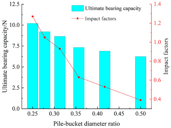
Figure 13.
The relationship of ultimate bearing capacity with the pile-bucket diameter ratio.
In Figure 13, it is evident that as the pile-bucket diameter ratio gradually decreases within the range of 1 to 0.25; the ultimate bearing capacity of the composite foundation progressively increases. To further analyze the influence of the pile-bucket diameter ratio on the ultimate bearing capacity of the composite foundation, the influence factor was introduced, where represents the ultimate bearing capacity of the foundation with a pile- bucket diameter ratio of 1 and represents the ultimate bearing capacity with a pile-bucket diameter ratio of α. When the pile-bucket diameter ratio decreases within the range of 0.5 to 0.357, the corresponding impact factors are 0.39, 0.53, and 0.63, indicating an approximate linear change. As the pile-bucket diameter ratio further decreases within the range of 0.357 to 0.25, the corresponding impact factors are 0.63, 0.93, 1.05, and 1.27, also exhibiting an approximately linear change but with a higher rate of increase compared to when the diameter ratio is greater than 0.357. This indicates that when the pile-bucket diameter ratio is within the range of 0.357 to 0.5, the increase in bucket diameter has a relatively small impact on the ultimate bearing capacity of the composite foundation and this influence follows a linear pattern. However, as the pile-bucket diameter ratio further decreases (≤0.357), the influence of the bucket diameter on the ultimate bearing capacity of the composite foundation becomes more pronounced. Therefore, the design of the horizontal ultimate bearing capacity of the wind turbine pile-bucket composite foundation should fall below 0.357 to fully utilize the advantages of the composite foundation.
5. Analysis of Deformation Characteristics of Soil around the Foundation
5.1. Analysis of the Deformation Mechanism of Soil around Pile-Bucket Composite Foundation under Different Compactness
To understand the deformation mechanism of the surrounding soil under different relative density levels, the displacement field of the composite foundation under horizontal monotonic loading was analyzed using the PIV (particle image velocimetry) technique. Figure 14 shows the displacement vector map corresponding to the pile-bucket composite foundation with a pile-bucket diameter ratio of 0.5 under ultimate load conditions in loose sand and dense sand states.
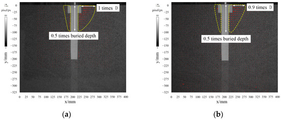
Figure 14.
Displacement vector field under different compactness. (a) Loose sand; (b) Dense sand.
By comparing the displacement fields under the two relative density states, it is evident that the influence depth of the surrounding soil is approximately 0.5 times the burial depth in both relative density states. Additionally, the range of influence of the surrounding soil around the composite foundation presents a triangular distribution. As the displacement gradually increases, the composite foundation detaches from the rear soil, forming a settlement zone, while the front soil of the composite foundation forms a bulging zone. The comparative analysis in Figure 15 reveals that under loose sand conditions, the range of influence on the surface of the front sand of the foundation is approximately the bucket diameter under horizontal loading. Under dense sand conditions, the range of influence on the surface of the front sand is approximately 0.9 times the bucket diameter. A comparison of the displacement fields of the sand surface under the two relative density states indicates that in the dense sand state, owing to the high relative density of the sand, the front sand of the foundation primarily displaces along the loading direction. In the loose sand state, the relative density of the front sand is lower, leading to sand separating and compacting towards both sides.
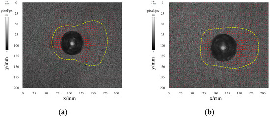
Figure 15.
The displacement vector field of soil surface under different compactness. (a) Loose sand; (b) Dense sand.
5.2. Analysis of the Soil Deformation Mechanism around a Pile-Bucket Composite Foundation under Different Pile-Bucket Diameter Ratios
To understand the deformation mechanism of the surrounding soil under the action of different pile-bucket diameter ratios, the displacement fields of the surrounding soil for the composite foundation under loose sand conditions with pile-bucket diameter ratios of d/D = 0.5, 0.417, and 0.357 were analyzed.
Figure 16 illustrates the displacement vector maps corresponding to the ultimate load under loose sand conditions for pile-bucket diameter ratios of 0.417 and 0.357. In conjunction with the analysis in Figure 14a, it becomes apparent that as the pile-bucket diameter ratio decreases, the influence depth of the surrounding soil around the foundation significantly decreases and the impact of the pile foundation top on the soil in the composite foundation also decreases. This indicates that as the pile-to-bucket diameter ratio decreases, the composite foundation primarily resists horizontal displacement through the bucket foundation.
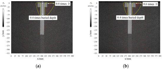
Figure 16.
Displacement vector field under different pile-bucket diameter ratios. (a) Pile-bucket diameter ratio d/D = 0.417; (b) Pile-bucket diameter ratio d/D = 0.357.
Figure 17 presents the surface displacement vector maps of the soil under loose sand conditions for pile-bucket diameter ratios of 0.417 and 0.357. In tandem with the analysis in Figure 15a, it is evident that as the pile-bucket diameter ratio decreases, the contact area between the composite foundation and the front soil expands, thereby amplifying the horizontal bearing capacity of the composite foundation. This also validates the distribution law of incremental earth pressure in Section 3.2. As the pile-bucket diameter ratio decreases, the bucket foundation shoulders more load. This aligns with the research results obtained by Li et al. [17] through numerical simulation, which analyzed the pile-bucket load-sharing ratio under horizontal loading.
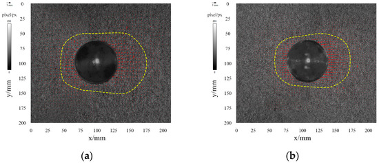
Figure 17.
The displacement vector field of soil surface under different pile-bucket diameter ratios. (a) Pile-bucket diameter ratio d/D = 0.417; (b) Pile-bucket diameter ratio d/D = 0.357.
6. Conclusions
This study investigates the bearing characteristics of foundations under horizontal monotonic loading through a combination of model experiments and numerical simulation. Utilizing PIV (particle image velocimetry) image acquisition and analysis techniques, the following conclusions are drawn:
- (1)
- Under identical pile-to-bucket diameter ratios, the horizontal load and displacement curves of the composite foundation exhibit consistent variations across different relative density conditions, dividing into stages of elastic deformation and elastoplastic deformation. Additionally, increased relative density results in a larger horizontal load borne by the bucket foundation in the composite foundation;
- (2)
- Within the same relative density level, the diameter of the bucket foundation in the composite foundation has a significant impact on its horizontal bearing performance. When the pile-bucket diameter ratio is between 0.357 and 0.5, the effect of bucket diameter on the ultimate bearing capacity of the larger composite foundation is relatively minor and follows a linear pattern. However, as the pile-bucket diameter ratio decreases further (≤0.357), the influence of bucket diameter on the ultimate bearing capacity of the composite foundation becomes more substantial;
- (3)
- Across different relative density levels, the shape of the influence range of the surrounding soil in the composite foundation is generally similar. Under loose sand conditions, the influence range extends more to the sides compared to dense sand conditions. A raised area forms on the front soil surface of the composite foundation, while a depression area forms on the rear soil;
- (4)
- Under varying pile-bucket diameter ratios, the depth of influence of the surrounding soil in the composite foundation significantly decreases. As the pile-bucket diameter ratio decreases, the influence of the pile foundation top on the soil in the composite foundation also diminishes.
Author Contributions
Conceptualization, X.Z.; Methodology, D.Y. and K.Z.; Software, A.Z. and D.Y.; Writing—original draft, D.Y.; Writing—review and editing, X.Z. and M.R. All authors have read and agreed to the published version of the manuscript.
Funding
This research was funded by grants from the Natural Science Foundation of China (Grant No. 41803033 and 41903034).
Institutional Review Board Statement
Not applicable.
Informed Consent Statement
Not applicable.
Data Availability Statement
The data presented in this study are available in the article.
Acknowledgments
We thank Minghui Jia, Chen Liu, and Jiming Sheng for their assistance in model testing and data analysis.
Conflicts of Interest
The authors declare no conflicts of interest.
References
- Faizi, K.; Faramarzi, A.; Dirar, S.; Chapman, D. Investigating the monotonic behaviour of hybrid tripod suction bucket foundations for offshore wind towers in sand. Appl. Ocean. Res. 2019, 89, 176–187. [Google Scholar] [CrossRef]
- Zhang, Y.; Li, D.; Liang, H.; Zhang, Y. Model tests on horizontal bearing capacity and earth pressure distribution of hollow cone-shaped foundation under horizontal monotonic loading. Rock Soil Mech. 2021, 42, 1404–1412. [Google Scholar]
- Bayton, S.M.; Black, J.A. Evaluating the p-Y Curve Method of Analysis for Large-Diameter Monopiles Using Centrifuge Modelling. In Geo-Chicago 2016: Geotechnics for Sustainable Energy; American Society of Civil Engineers: Chicago, IL, USA, 2016; pp. 418–428. [Google Scholar]
- Liu, R.; Li, B.; Lian, J.; Ding, H. Bearing Characteristics of Pile-Bucket Composite Foundation for Offshore Wind Turbine. J. Tianjin Univ. (Sci. Technol.) 2015, 48, 429–437. [Google Scholar]
- Wang, J.; Sun, G.; Chen, G.; Yang, X. Finite element analyses of improved lateral performance of monopile when combined with bucket foundation for offshore wind turbines. Appl. Ocean. Res. 2021, 111, 102647. [Google Scholar] [CrossRef]
- Sun, Y.; Xu, C.; Du, X.; Wang, P.; Xi, R.; Sun, Y. Bearing characteristics of pile-bucket composite foundations for offshore wind turbines. Chin. J. Eng. 2023, 45, 489–498. [Google Scholar]
- Huang, Z.; Wu, F.; Su, J. Vertical Bearing Capacity of Pile-bucket Composite Foundation for Offshore Wind Turbine. J. Hydroelectr. Eng. 2017, 43, 83–86+100. [Google Scholar]
- Zhou, E.; Xu, X.; Lu, J. Horizontal bearing capacity of pile-bucket composite foundation of offshore wind turbine. J. Jiangsu Univ. (Nat. Sci. Ed.) 2022, 43, 235–241. [Google Scholar]
- Wang, X. Analysis of bearing capacity attenuation for pile-bucket composite foundation under cyclic loading. Shanxi Archit. 2020, 46, 61–63. [Google Scholar]
- Chen, D.; Gao, P.; Huang, S.S.; Li, C.; Yu, X. Static and dynamic loading behavior of a hybrid foundation for offshore wind turbines. Mar. Struct. 2020, 71, 102727. [Google Scholar] [CrossRef]
- Liu, H.; Zhang, P.; Wang, Q.; Yang, Q. Optimum structural design and loading advantage analysis of pile-bucket foundation. J. Harbin Eng. Univ. 2018, 39, 1165–1171. [Google Scholar]
- Chen, W.; Jiang, Y.; Xu, L.; Liu, C.; Chen, G.; Wang, P. Seismic response of hybrid pile-bucket foundation supported offshore wind turbines located in liquefiable soils. Ocean. Eng. 2023, 269, 113519. [Google Scholar] [CrossRef]
- Li, L.; Liu, H.; Jiang, G.; Liu, Z.; El Naggar, M.H.; Wu, W. Numerical analysis on the mechanical response of grouted connection for pile-bucket foundation. Ocean. Eng. 2023, 287, 115790. [Google Scholar] [CrossRef]
- Li, L.; Liu, X.; Liu, H.; Wu, W.; Lehane, B.M.; Jiang, G.; Xu, M. Experimental and numerical study on the static lateral performance of monopile and hybrid pile foundation. Ocean. Eng. 2022, 255, 111461. [Google Scholar] [CrossRef]
- Kuo, Y.S.; Achmus, M.; Abdel-Rahman, K. Minimum embedded length of cyclic horizontally loaded monopoles. J. Geotech. Geoenviron. Eng. 2012, 138, 357–363. [Google Scholar] [CrossRef]
- Kang, F.; Jie, P. Detailed Explanation of ABAQUS Geotechnical Engineering Examples; Posts & Telecom Press: Beijing, China, 2017. [Google Scholar]
- Shi, L.; Yuan, Z.; Yuan, Z.; Sun, H.; Cai, Y. On load-bearing and soil-reacting characteristics of hybrid pile-bucket foundations subjected to static horizontal loading. Mar. Struct. 2022, 84, 103222. [Google Scholar] [CrossRef]
Disclaimer/Publisher’s Note: The statements, opinions and data contained in all publications are solely those of the individual author(s) and contributor(s) and not of MDPI and/or the editor(s). MDPI and/or the editor(s) disclaim responsibility for any injury to people or property resulting from any ideas, methods, instructions or products referred to in the content. |
© 2024 by the authors. Licensee MDPI, Basel, Switzerland. This article is an open access article distributed under the terms and conditions of the Creative Commons Attribution (CC BY) license (https://creativecommons.org/licenses/by/4.0/).