Article

Multi-Objective Cutting Parameter Optimization Method for the Energy Consumption and Machining Quality of Computerized Numerical Control Lathes

1
School of Mechatronics Engineering, Henan University of Science and Technology, Luoyang 471000, China
2
High-End Bearing Collaborative Innovation Center of Henan Province, Luoyang 471000, China
*
Author to whom correspondence should be addressed.
Appl. Sci. 2024, 14(2), 905; https://doi.org/10.3390/app14020905
Submission received: 19 December 2023 / Revised: 15 January 2024 / Accepted: 16 January 2024 / Published: 21 January 2024

Abstract

:
In order to achieve minimum energy consumption in computerized numerical control (CNC) lathe processing under the premise of ensuring the imposed roughness of the machined surface, a black hole-continuous ant colony optimization algorithm (BH-ACOR) is proposed to optimize the turning parameters. Taking turning specific energy and surface roughness as the optimization objectives, a turning test was designed. Subsequently, a multi-objective mathematical model of the cutting stage was formulated through the application of the least-squares method to fit the test data. The black hole algorithm was introduced to mitigate the shortcomings of the continuous-domain ant colony algorithm, which easily falls into a local optimum, so as to put forward a kind of BH-ACOR that is applicable to multi-objective optimization. The algorithm was applied to the multi-objective mathematical model in the turning stage to determine the optimal cutting parameters. Through simulation and test verification, the validity and practicability of the proposed method are further proved.

1. Introduction

As the pillar industry supporting the national economy, the manufacturing industry plays an important role in economic globalization and sustainable development. However, while the manufacturing industry is advancing at a rapid pace, excessive energy consumption and large amounts of greenhouse gas emissions are becoming increasingly serious. Determining how to sustainably realize low energy consumption and high efficiency in the manufacturing industry has also become a key issue in the global manufacturing industry. In close relation to this, the improvement of energy management for high-energy-consumption equipment in the manufacturing industry has become the research object of many scholars. As basic pieces of equipment for manufacturing processing systems, CNC lathes have a large number of machine tools, high energy consumption, and an average energy efficiency of less than 30% [1]. Machining industry practitioners are eager to find solutions to reduce the energy consumption of CNC lathe machining.
In CNC turning, the thoughtful selection of cutting parameters can not only diminish the energy consumption of the lathe but also significantly enhance the machining surface quality. To optimize energy consumption, the first step is to analyze the functional relationship between the processing energy consumption and cutting parameters of a CNC lathe. Gutowski et al. [2] established the relationship between the machining input power of a CNC lathe and the material removal rate in the cutting state by analyzing the power change law in the CNC turning process. Subsequently, Kara et al. [3] improved the formula and established a cutting specific energy model that can reflect the relationship between the cutting energy consumption and the material removal rate of a CNC lathe. At present, CNC lathe energy consumption optimization models are established by taking cutting specific energy, the material removal rate, and other factors as the optimization target, and different algorithms are used to select the optimal cutting parameters so as to reduce cutting energy consumption and improve a material’s surface quality. For example, Feng et al. [4] examined the impact of energy consumption on non-processing factors such as automatic tool change, common feed, and rapid feed; established a multi-objective mathematical model with cutting energy consumption, processing quality, and processing time as the optimization objectives; and used the non-dominated genetic algorithm (NSGA-II) for multi-objective optimization. Song et al. [5] established a multi-objective cutting parameter optimization model with 30CrMnSiNiA steel as the cutting material and surface roughness and material removal rate as the objectives and used the improved multi-objective Harris Hawk algorithm (MOHHO) for optimization. Li et al. [6] used the response surface method to analyze the effect of cutting parameters on cutting force and cutting temperature to establish mathematical models of cutting force and material removal rate and used a genetic algorithm for multi-objective optimization. Camposeco et al. [7] used AISI1045 steel as the cutting material to establish a multi-objective mathematical model with cutting specific energy and material surface roughness as the optimization objectives, and the response surface method was used to obtain a regression model of the study variables so as to maximally optimize the energy efficiency and material surface quality. Su et al. [8] used a blend of grey correlation analysis and response surface methodology to select the optimal machining parameters for turning AISI 304 austenitic stainless steel. This approach led to a notable 66.9% decrease in surface roughness and an 81.46% decrease in specific energy consumption. Feng et al. [9] considered cutting energy consumption and non-cutting energy consumption; established a multi-objective mathematical model with energy consumption, machining surface quality, and machining time as the optimization objectives; and solved the optimal Pareto solution set. Song et al. [10] introduced a dynamic multiple-swarm particle swarm algorithm that preserves infeasible particles generated by the particle swarm algorithm and used the separation index method to continuously adjust the range of constraints in the multi-objective problem. They then selected the optimal machining energy and machining cost, the model for which was verified using the AD-35 CNC lathe. Wang et al. [11] considered the long cycle time, high energy consumption, and high wear of CNC grinding machines; established a mathematical model with quality cost and energy loss as the optimization objectives; and used the NSGA-II algorithm for optimization. The outcomes demonstrated a 30.2% reduction in carbon emissions and an 18.4% decrease in total cost while ensuring accuracy. Although previous researchers have made some progress in the multi-objective optimization of cutting parameters for CNC lathes, the above optimization algorithms have limitations in terms of optimization ability and efficiency. For example, Su et al. [8] used a combination of grey correlation analysis and response surface analysis to compare and select the optimal solution within a pre-set limited combination of machining parameters, ignoring other combinations within the constraint interval. The quality of the optimal solution needs to be further improved. The dynamic multi-swarm particle swarm algorithm proposed by Song et al. [10] mainly adopts the calculation steps of particle swarm optimization, while traditional particle swarm algorithms have low accuracy, are prone to divergence, and the quality of their corresponding search results is not high. Therefore, further research is needed to improve the multi-objective optimization method used to optimize the cutting parameters of CNC lathes.
The continuous ant colony optimization algorithm (ACOR) was originally proposed by Dorigo [12]. It is more suitable for solving continuous function optimization problems than the original ant colony algorithm. The ACOR has been widely used to address engineering problems such as ship longitudinal motion parameter optimization [13] and the design of lightweight crane girders [14] and provides a new solution with which to address processing energy consumption in CNC workshops. However, the ACOR easily falls into a local optimum and cannot easily exit the local optimum region due to its high convergence speed. The black hole optimization algorithm (BH) [15] uses high-quality solutions to guide the optimization direction, can fully search in a limited space, and helps to improve the diversity of solutions. Starting from the disadvantages and the limits of the above algorithms, this paper deals with a substantial improvement, consisting of the combination of the black hole and ant colony algorithms. The new algorithm, suggested to be named BK-ACOR, is able to overcome the limits (mainly relating to falling into local optima) of the algorithms used before and, at the same time, is suited for the multi-objective optimization of cutting energy consumption and material surface roughness while machining on a CNC lathe.

2. Multi-Objective Optimization Modeling in Material Cutting Stage of CNC Lathe

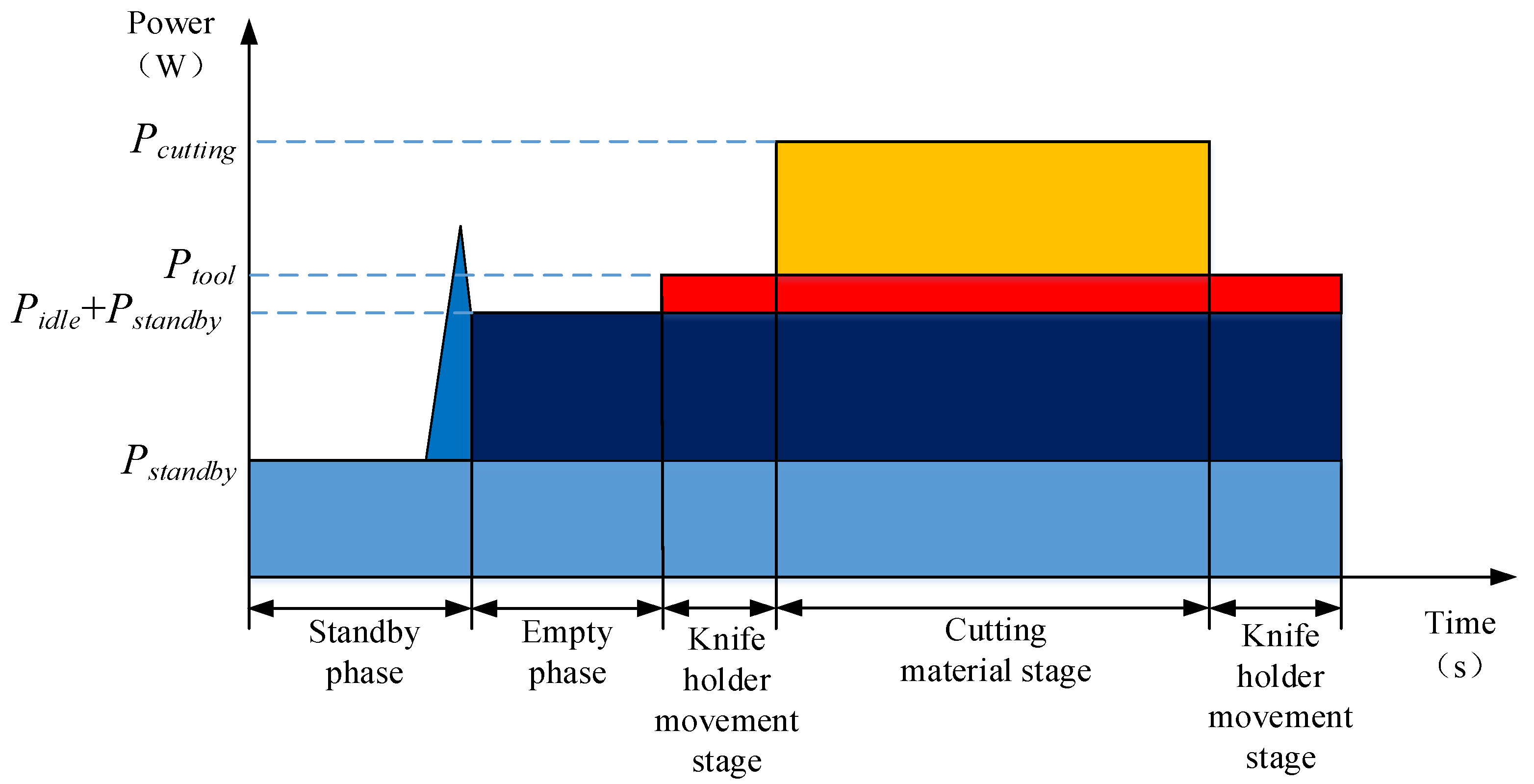
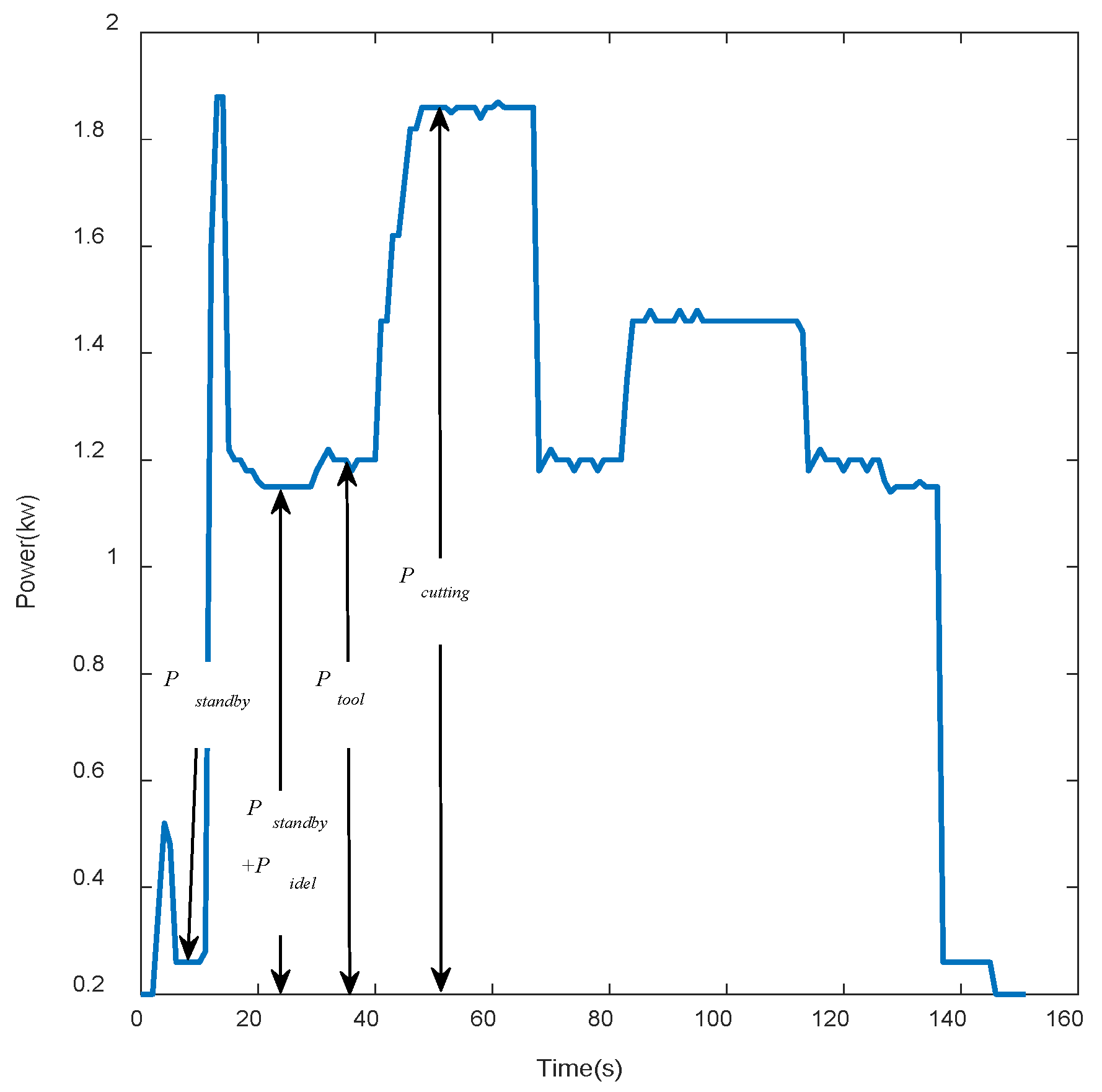
2.1. Modeling Process

The complete machining process of a CNC lathe can be divided into a standby stage, a spindle-idling stage, a tool-carrier-moving stage, and a cutting material stage. Depending on the source of energy consumption, the energy consumption of each stage is related to the working power of the parts involved in the work. The power of each stage is expressed as the standby power P s t a n d b y , the idle power of the main shaft P i d l e , the moving power of the tool holder P t o o l , and the cutting material power P c u t t i n g . The power compositions of each stage are shown in Figure 1.
It can be seen that the standby and no-load phases primarily involve the operation of auxiliary systems and the rotation of the spindle. After stable operation, P s t a n d b y and P i d l e are basically fixed values, and the optimization space is small [16]. Although the tool resting stage occurs throughout the entire turning process, the power of the feed shaft motor driving the tool rest movement is low, and P t o o l is proportional to the feed rate, so optimization is of little significance. P c u t t i n g changes dramatically during the cutting material phase, wherein the power is directly influenced by the turning force F c . In case of cutting, F c is related to the cutting speed v c (m/min), feed rate f (mm/r), and depth of cut a p (mm). Therefore, the power P c when turning materials can be expressed as follows:
P c = P c u t t i n g P t o o l = F c v c = C F v c x f y a p z K F
Here, C F , x , y , z , and K F are coefficients related to machine tools and materials [17].
The specific energy of cutting (SEC), an index used to measure processing energy consumption [17], is expressed by Formula (2):
S E C = E V
where E is the total energy consumption of the cutting material, and V is the volume of material removed.
As can be seen from the above equation, if the cutting specific energy in a machining operation is lower, less energy will be consumed when cutting the same volume of material because the volume of processed material is not exactly the same in actual processing. Therefore, power cannot be used as the energy consumption index. Therefore, the energy consumption per unit volume of material, as indicated by the specific energy of cutting (SEC), was adopted as the energy consumption index. Under a certain processing amount, the lower the cutting energy, the less electrical energy consumed by the machine tool.
By dividing the numerator and the denominator of Equation (3) by the processing time t at the same time, we obtain
S E C = E / t V / t = P c M R R
where MRR (mm3/s) is the material removal rate, indicating the volume of material removed per second, and is expressed by Equation (4) as follows:
M R R = 1000 v c f a p 60
By combining Equations (1), (3), and (4), an expression in the form of the cutting specific energy index can be obtained, as shown in Equation (5):
S E C = K v c m f n a p r
Here, K = 60 C F K F 1000 , m = x 1 , n = y 1 , and r = z 1 .
In addition to energy consumption, machining quality is also a goal that producers focus on, and surface roughness is commonly used in engineering to measure machining quality [17]. The complex relationship between surface roughness and cutting parameters can be approximated in exponential form, as shown in Equation (6):
R a = k 0 v c k 1 f k 2 a p k 3

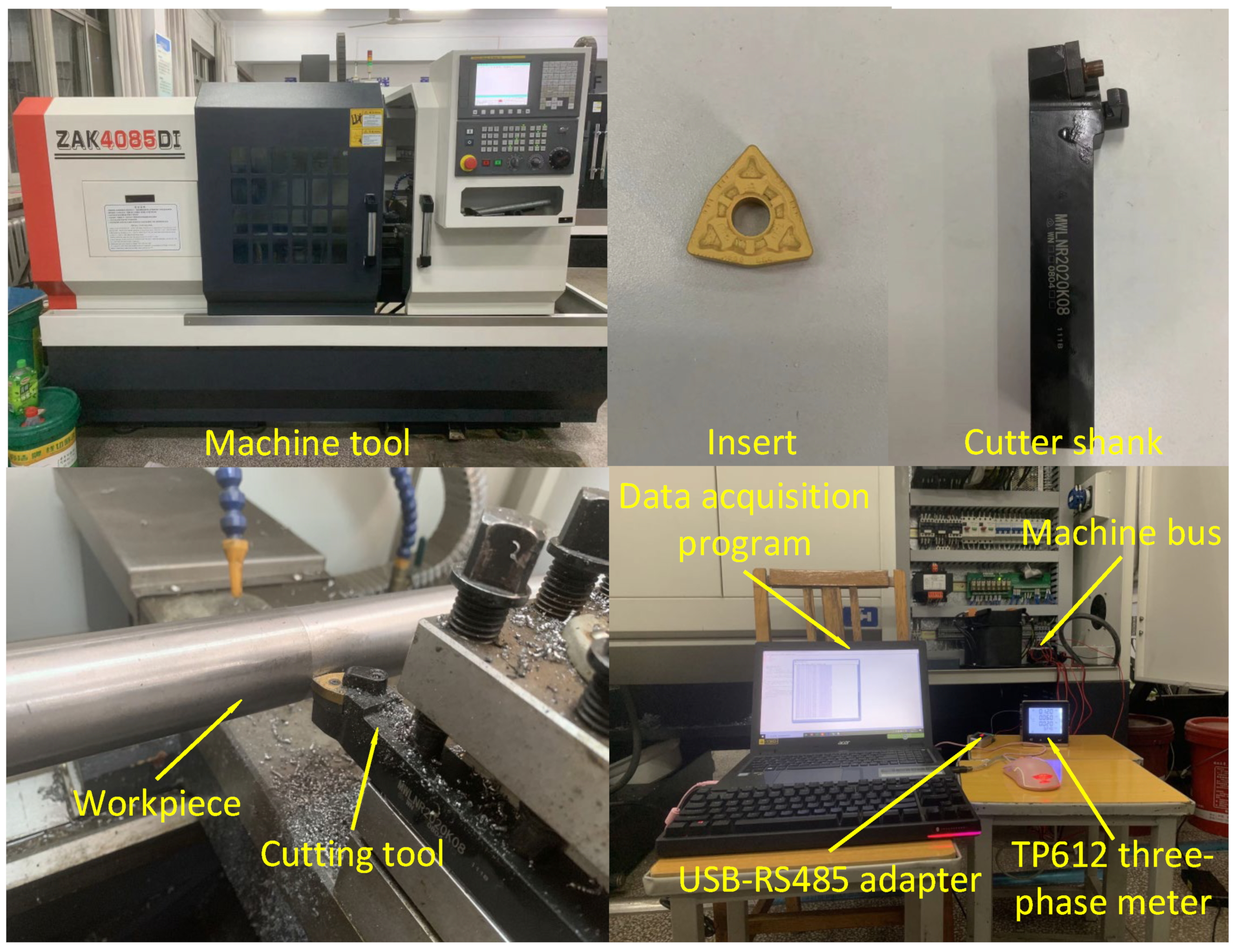
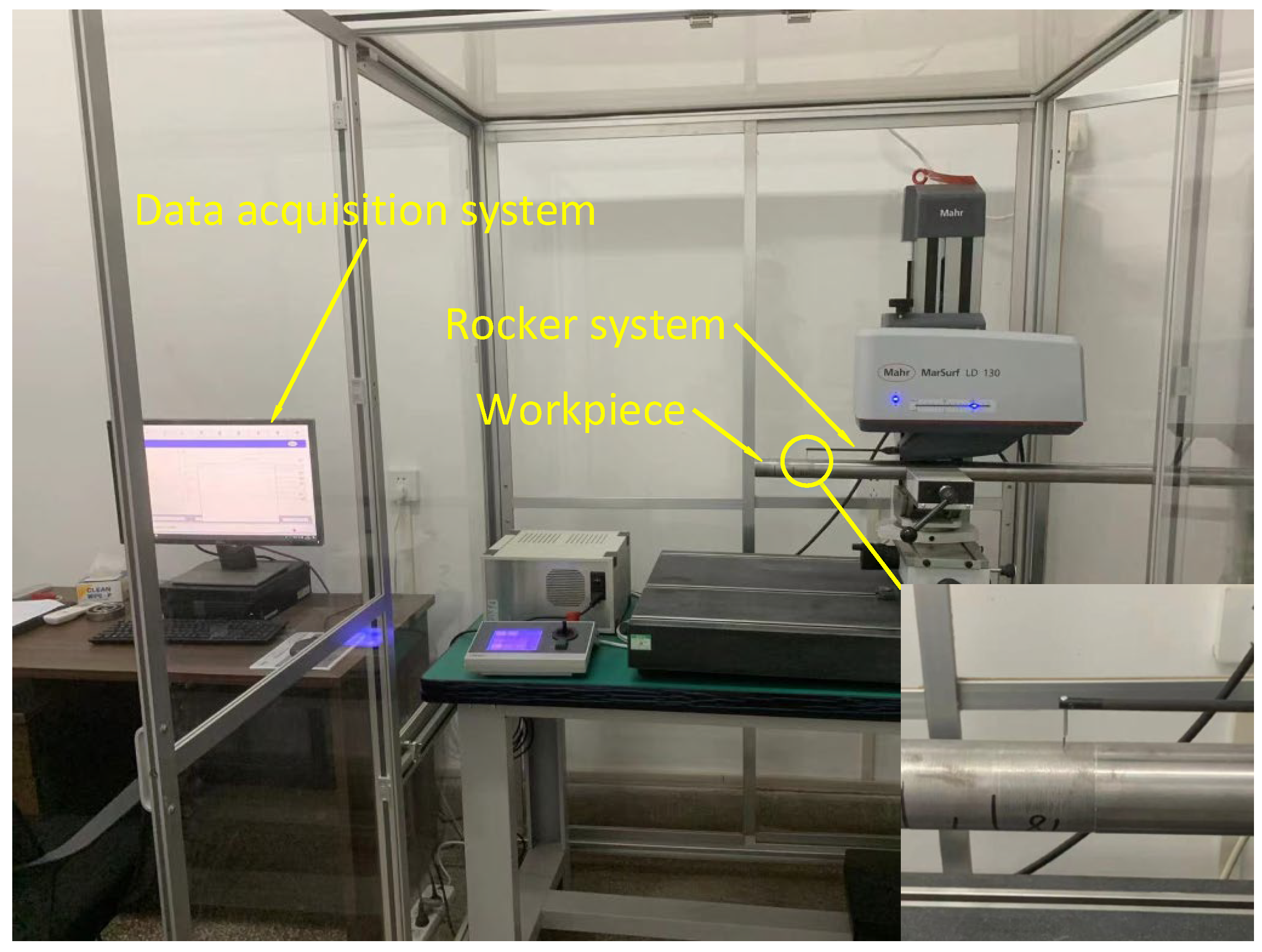
2.2. Test Conditions and Data Acquisition
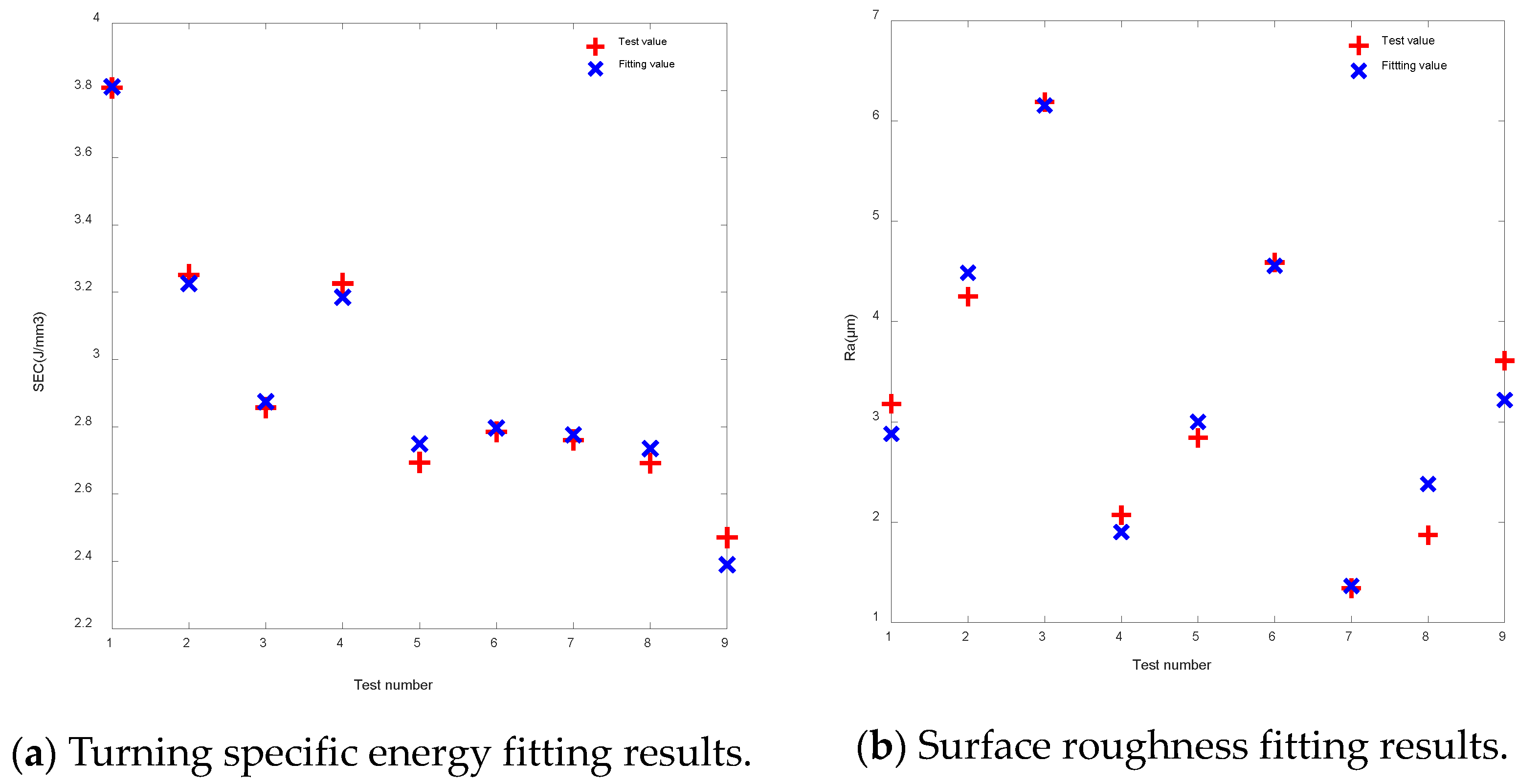
The dry turning of 45 steel was carried out by using a ZAK4085DI CNC lathe manufactured by Shanghai KeRong (Shanghai, China). The maximum turning diameter of the lathe body is 400 mm, the maximum speed is 2400 r/min, and the maximum power of the spindle is 7.5 kW. The machining tool used was a carbide tool made by Zhuzhou Diamond (Zhuzhou, China), namely, model WNMG080408. The diameter of the piece of 45 steel ϕ d was 40 mm, and its length was 500 mm. A TP612 three-phase multi-function ammeter was used to measure the active power at the bus of the machine tool, and a program was written in the Python3.9 language to record the active power at a fixed interval of 0.5 s. The final test platform is shown in Figure 2, and the power curve of a complete machining process is shown in Figure 3.
Machined surface roughness values were acquired by employing a MarSurf LD130 (Manufacturer: Mahr, Eislingen, Germany) from Germany, and the instrument used is shown in Figure 4. This instrument uses a rocker system with a tip to contact the measured workpiece. During the rocker’s movement, the swing angle is mapped to the diffraction grille at the end via a diode light to generate an interference pattern. Finally, the data acquisition system draws the contour curve of the measured workpiece and calculates its surface roughness value.
According to the tool manufacturer’s recommendations and the bearing capacity of the CNC lathe employed, the cutting speed v c , feed rate f , and depth of cut a p were set to three levels, as shown in Table 1. The Taguchi method was used to design nine tests, and the results of each turning test are listed in Table 2.

2.3. Model Building

Equations (5) and (6) are nonlinear equations. Equations (5) and (6) can be transformed into linear forms by computing the logarithms of both sides and considering the new unknowns equal to the logarithm of the corresponding originals. Take Equation (7) as an example:
ln S E C = ln C + ( x 1 ) ln v c + ( y 1 ) ln f + ( z 1 ) ln a p
Let us set y = ln S E C , β 0 = ln C , β 1 = x 1 , β 2 = y 1 , β 3 = z 1 , x 1 = ln v c , x 2 = ln f , and x 3 = ln a p ; then, Equation (8) can be converted into a linear equation:
y = β 0 + β 1 x 1 + β 2 x 2 + β 3 x 3
β 0 , β 1 , β 2 , and β 3 are the regression coefficients. The regression coefficients are the solution to a linear system with nine equations and four unknowns, whose matrix form is as follows, as shown in Equation (9):
Y = X β
where Y = y 1 y 2 y 9 , X = 1 x 1 , 1 x 1 , 2 x 1 , 3 1 x 2 , 1 x 2 , 2 x 2 , 3 1 x 9 , 1 x 9 , 2 x 9 , 3 , and β = β 0 β 1 β 2 β 3 .
The estimating parameters can be set using the least squares method β . Let b 0 , b 1 , and b 2 be the least squares estimates of the parameters β 0 , β 1 , β 2 , and β 3 , respectively, and y ^ be the regression value of the test result y i ; then, the regression Equation (10) is as follows:
y ^ i = b 0 + b 1 x i , 1 + b 2 x i , 2 + b 3 x i , 3
According to the principle of the least squares method, the sum of squares of a random error ε i should be minimized, and ε i is the difference between the test result y i and the regression value y ^ . Then, the sum of squares of the random errors of the nine groups of tests is expressed as Q :
Q = i = 1 9 ε i = i = 1 9 ( y i y ^ i ) 2 = i = 1 9 ( y i b 0 b 1 x i , 1 b 2 x i , 2 b 3 x i , 3 ) 2
Set b = [ b 0   b 1   b 2   b 3 ] T , according to the extreme value principle; calculate the first derivative of Q versus b ; and set the derivative equal to zero. After simplification, we can finally obtain the following:
b = b 0 b 1 b 2 b 3 = ( X T X ) 1 X T Y = 2.819 0.552 0.264 0.106
Since b 0 = ln C = 2.819 , C = 16.75 . Thus, the final turning specific energy model of the cutting parameters is shown in Equation (13):
S E C = 16.75 v c 0.552 f 0.264 a p 0.106
Similarly, the function expression of surface roughness Ra is shown in Equation (14):
R a = 0.965 v c 0.565 f 0.4 a p 0.035
Comparisons between the fitting value of the turning specific energy and surface roughness model and the test value are shown in Figure 5a and Figure 5b, respectively. The correlation coefficient R is equal to 0.98, and R2 is equal to 0.97, between the fitting value of the turning specific energy and the actual value; regarding model significance, P = 0.01 < 0.05 . For the surface roughness model, R = 0.983 and R2 = 0.967, while the model significance corresponds to P = 0.02 < 0.05 . This means that the cutting specific energy calculated using Equations (13) and (14) has a strong linear relationship with the test value, indicating that the established model meets the fitting requirements.
In order to verify the reliability of the established model, five groups of test data were selected for verification, and the errors of the turning specific energy SEC and surface roughness Ra obtained via formula fitting and testing were compared. The results of the verification of the turning process are shown in Table 3. Among the five sets of test data, the average error of the SEC is 0.17 J/mm3, with an average error percentage of 5.89%, and the average error of Ra is 0.22 μm, with an average error percentage of 4.86%. These results show that the developed model has high accuracy, effectively predicting both turning specific energy SEC and surface roughness Ra.
According to the mathematical expressions of cutting specific energy and surface roughness, as well as the production conditions that must be met by turning parameters, the multi-objective optimization model of a CNC lathe in the material-cutting stage can be determined as follows:
min S E C = 16.75 v c 0.552 f 0.264 a p 0.106 min R a = 7977 v c 1.658 f 1.190 a p 0.09 v c min v c v c max f min f f max a p min a p a p max P c = C F v c x + 1 f y a p z K F 7.5 kW
The weighted summation method is frequently employed to convert multi-objective optimization problems into their single-objective counterparts. Due to the different magnitudes of cutting specific energy and surface roughness, it is necessary to normalize the two objective functions. Different weight coefficients are set for each optimization objective according to the different efficiency goals pursued. The larger the coefficient, the more emphasis is placed on the optimization of specific cutting energy and, conversely, the lower the machined surface roughness.
The weighted optimization objective function is shown in Equation (16):
min F = min ( c S E C * + ( 1 c ) R a * )
where c and 1 − c are the weighting coefficients for cutting specific energy and machined surface roughness, respectively; c = 0.1, 0.2, …, 0.9; and SEC* and Ra* are the normalized cutting specific energy and machined surface roughness functions, respectively.
The normalization process is defined as follows:
f i * = f i f i , min f i , max f i , min
where f i , max and f i , min are the maximum and minimum values of each objective function for single-objective optimization, respectively.

3. Solving Optimal Cutting Parameters Using Black Hole-Continuous Ant Colony Algorithm

3.1. Introduction to Continuous Ant Colony Algorithm

The continuous ant colony algorithm (ACOR) is built upon the ant colony algorithm (ACO) and utilizes a Gaussian kernel function for sampling to generate new solutions. This extends the discrete search space to the continuous domain. The algorithm proceeds as follows:
Step 1: Generate k ants randomly in the definition domain, calculate their function values F ( x i ) according to Equation (16), and rank them according to the results from smallest to largest.
Step 2: Calculate the weight ω i of each solution based on the ranking number i with the following formula:
ω i = 1 q k 2 π e ( i 1 ) 2 2 q 2 k 2
where i = 1 , 2 , , k denotes the i-th solution; q is the reinforcement factor, and the smaller its value, the more the algorithm tends to select the top-ranked solution.
Step 3: Calculate the probability of each solution being selected ( p i ).
p i = ω i i = 0 k ω i
Step 4: Select a guide solution x i according to the probability of step 3, and sample the n dimensions of x i  m times using a weighted Gaussian kernel function G j ( x ) . The sampling process is expressed as follows:
G j ( x ) = i = 1 k ω i g i j ( x ) = i = 1 k ω i 1 σ i j 2 π e ( x μ i j ) 2 2 σ i j
where j = 1 , 2 , n , the mean corresponds to μ i j = x i j , and σ i j is the standard deviation, which is calculated as follows:
σ i j = ξ e = 1 k x e j x i j k 1
where ξ is the offset distance ratio, and its value is greater than 0. The larger the value of ξ, the slower the algorithm converges.
Step 5: After sampling to generate m new solutions, calculate their function values F(xi) again according to Equation (16) and merge them with the previous k ants; arrange them according to the function values from smallest to largest; and select the first k results from these k + m ants as better solutions, and the last m as inferior solutions, and discard them. Then, return to step 2 until the termination of the iteration.

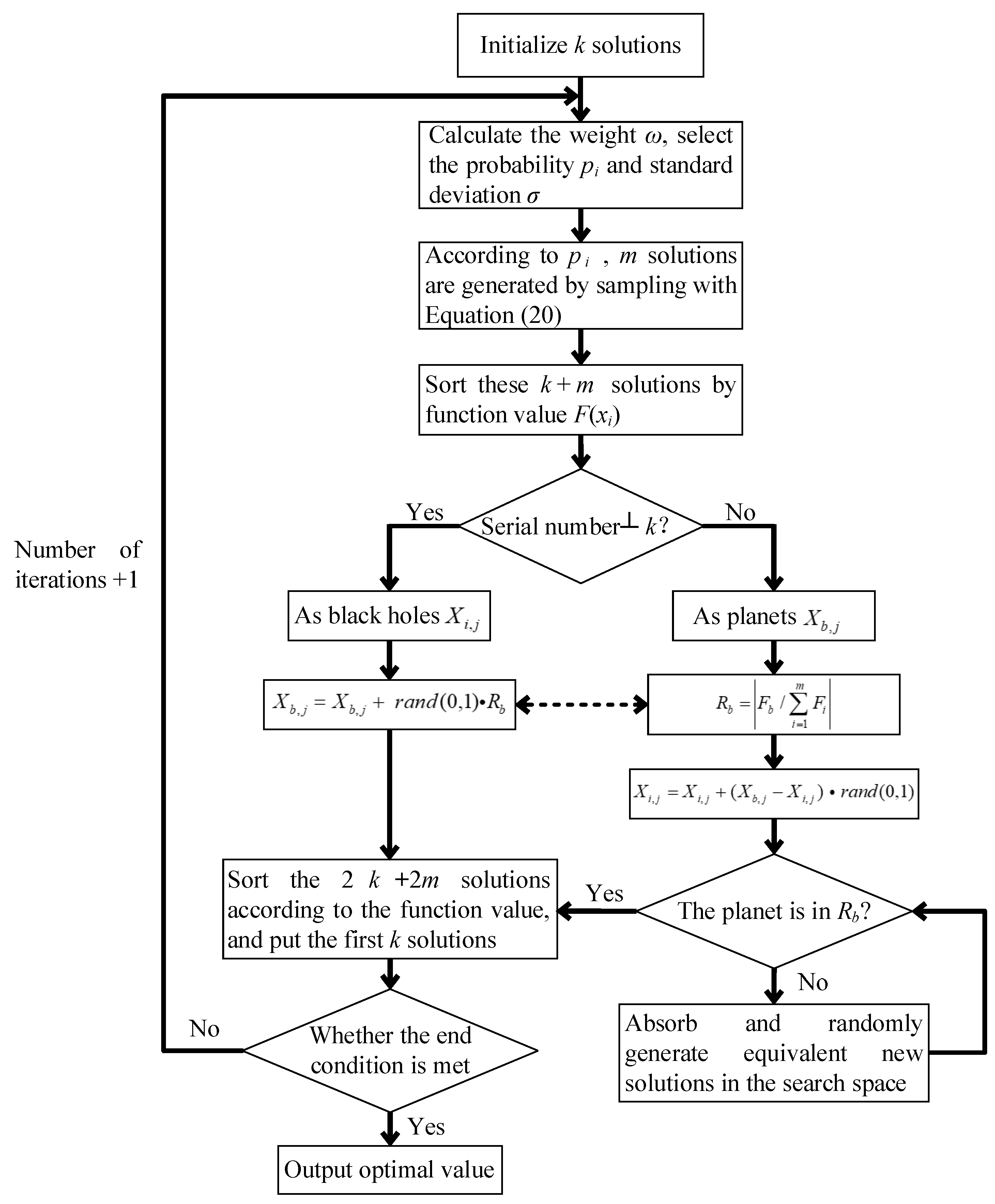
3.2. The Proposed Black Hole-Continuous Ant Colony Algorithm

Although the ACOR has fast convergence speed; however, due to the low diversity of solutions in the optimization process, falling into local optima is a common challenge. After each iteration, the ACOR only selects the first k superior solutions for the next iteration, and the next m inferior solutions are discarded, so after running for a period of time, the probability of relatively superior solutions being selected as the guiding solutions is too high, resulting in the standard deviation vector σ i j gradually tending toward 0 and failing to produce new solutions and the disappearance of solution diversity. Given that the energy consumption optimization model of a CNC lathe is a non-linear function involving two objectives and three variables, it is likely to exhibit multiple instances of local optima, so the ACOR cannot be guaranteed to exit the local optimum area. Combining the black hole algorithm with ACOR resulted in the formation of a hybrid algorithm known as BH-ACOR, which was utilized to address this issue. The BH-ACOR’s distinctive feature is to process both the good and the bad solutions sorted in step 5 of the ACOR. It designates the first k superior solutions as black holes and the last m inferior solutions as planets. Each planet is drawn towards the direction of the black holes to facilitate global search. Black holes, however, do not attract each other, hoping to discover better solutions during the movement process, thereby expanding the search scope and enhancing the variety of solutions. For the black hole itself, a dynamic local search strategy is used to improve optimization accuracy.
If k solutions are generated randomly in the search space defined by Formula (15), the position of the i-th solution, encompassing three variables, can be expressed as follows:
x i = ( x i 1 , x i 2 , x i 3 ) = ( v c i , f i , a p i )
Perform ACOR steps 2–4 or the generation of m new solutions. Because there are only three cutting parameters, leading to sampling that generates too many new solutions, this may lead to the repetition of solutions, subsequently impacting the optimization process negatively. So, the number of solutions, m, generated per iteration should be set to 50. Calculate the function values associated with each solution using Equation (16) and subsequently arrange them in sorted order. The first k solutions that result in relatively small values for cutting specific energy and surface roughness are regarded as black holes, while the last m solutions are regarded as planets.
(1)
Planetary global search
The planets will move towards the black hole in a global search to generate m new solutions, whose search algorithm can be expressed as
X i , j = X i , j + ( X b , j X i , j ) × r a n d ( 0 , 1 )
where i = 1 , 2 , , m , 50 denotes the i-th planet, b = 1 , 2 , , k denotes the b black hole, j = 1 , 2 , 3 denotes the j dimension, X i , j denotes the position of the i planet in the j dimension, and X b , j denotes the position of the b black hole in the j dimension.
Since a black hole can absorb the material around it, when the planetary movement is complete, determine whether the planet is within the black hole’s absorption radius, R b . Define R b as follows:
R b = F b i = 1 m F i
where F b denotes the size of the function value for the b black hole and F i denotes the size of the function value for the i planet.
When the absolute value of the difference between F i and F b is compared with R b , if the absorption radius is outside R b , the moved planet R b will be preserved; if it is within the absorption radius R b , the moved planet X i , j will be absorbed (becoming void). In addition, in order to ensure that the total number of planets in the search space remains unchanged, the number of planets absorbed by the black hole must be supplemented in the search space by an equal number of planets, and it must again be determined whether the newly generated planets are within the absorption radius R b . The process can be expressed as Formula (25):
X i , j = X i , j , F i F b R b b l a n k ,   F i F b R b
(2)
Black hole local search
The original black hole algorithm indicated that the solution represented by the black hole itself was deemed satisfactory. As a result, only the planets moved toward the black hole, with the black hole itself remaining stationary [18]. But for the nonlinear function optimization problem of CNC lathe energy consumption, it is possible to have a global optimal solution near the black hole. In order to improve the accuracy of the solution, the BH-ACOR algorithm generates k new solutions through a local search of k black holes in the space with radius R b . The local search process of a black hole is shown in Equation (26):
X b , j = X b , j + r a n d ( 0 , 1 ) × R b
2 m + 2 k solutions related to planets and black holes are sorted, and the first k solutions are used for a new round of iterative calculation. The steps of the BH-ACOR algorithm are shown in Figure 6.

4. Optimization Results and Verification

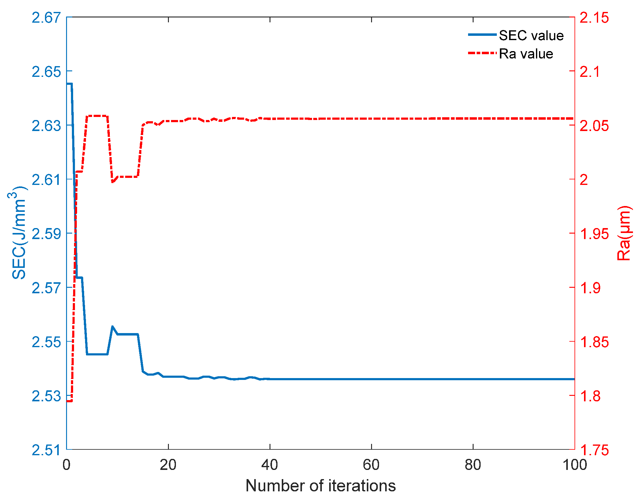
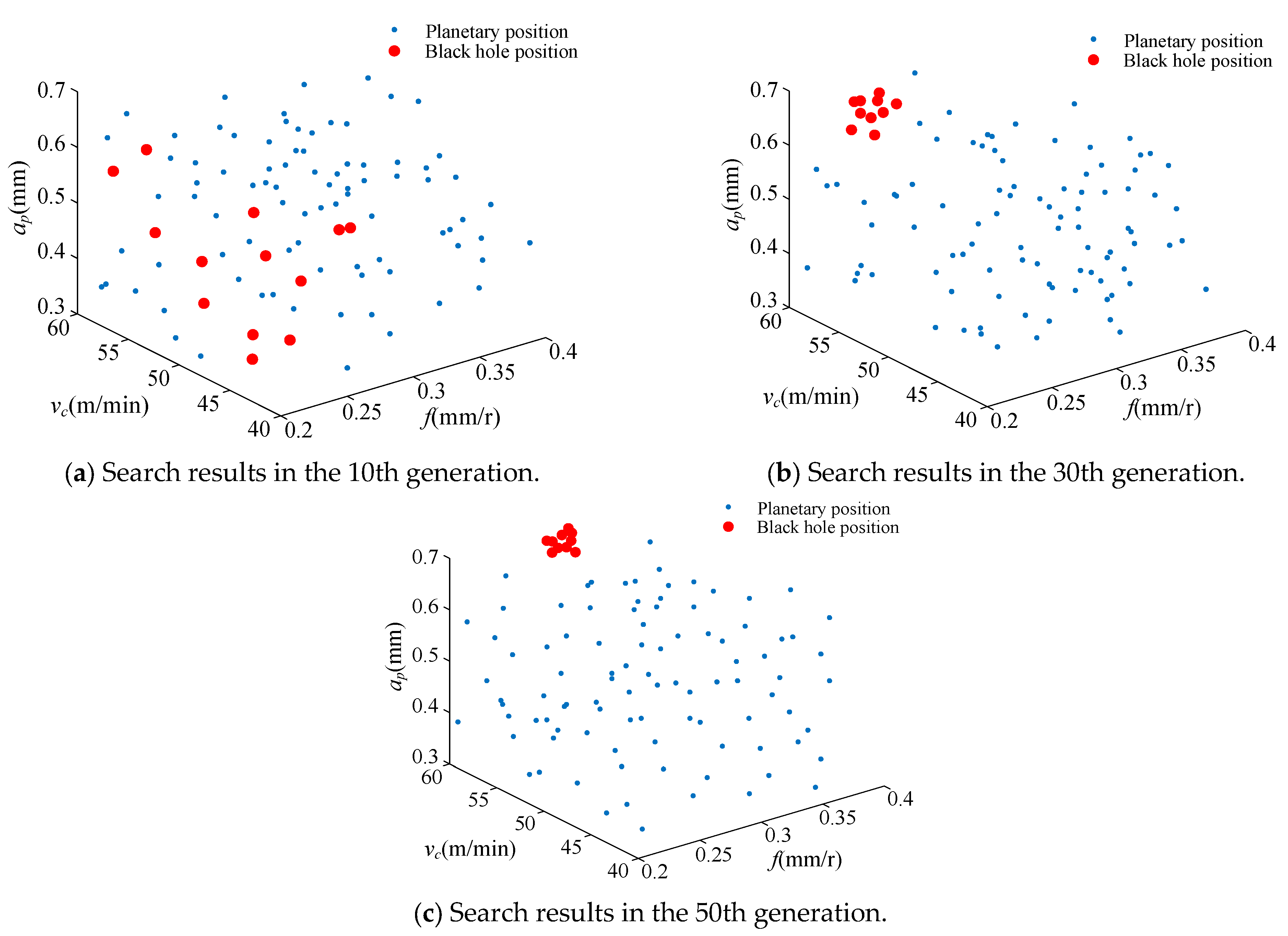
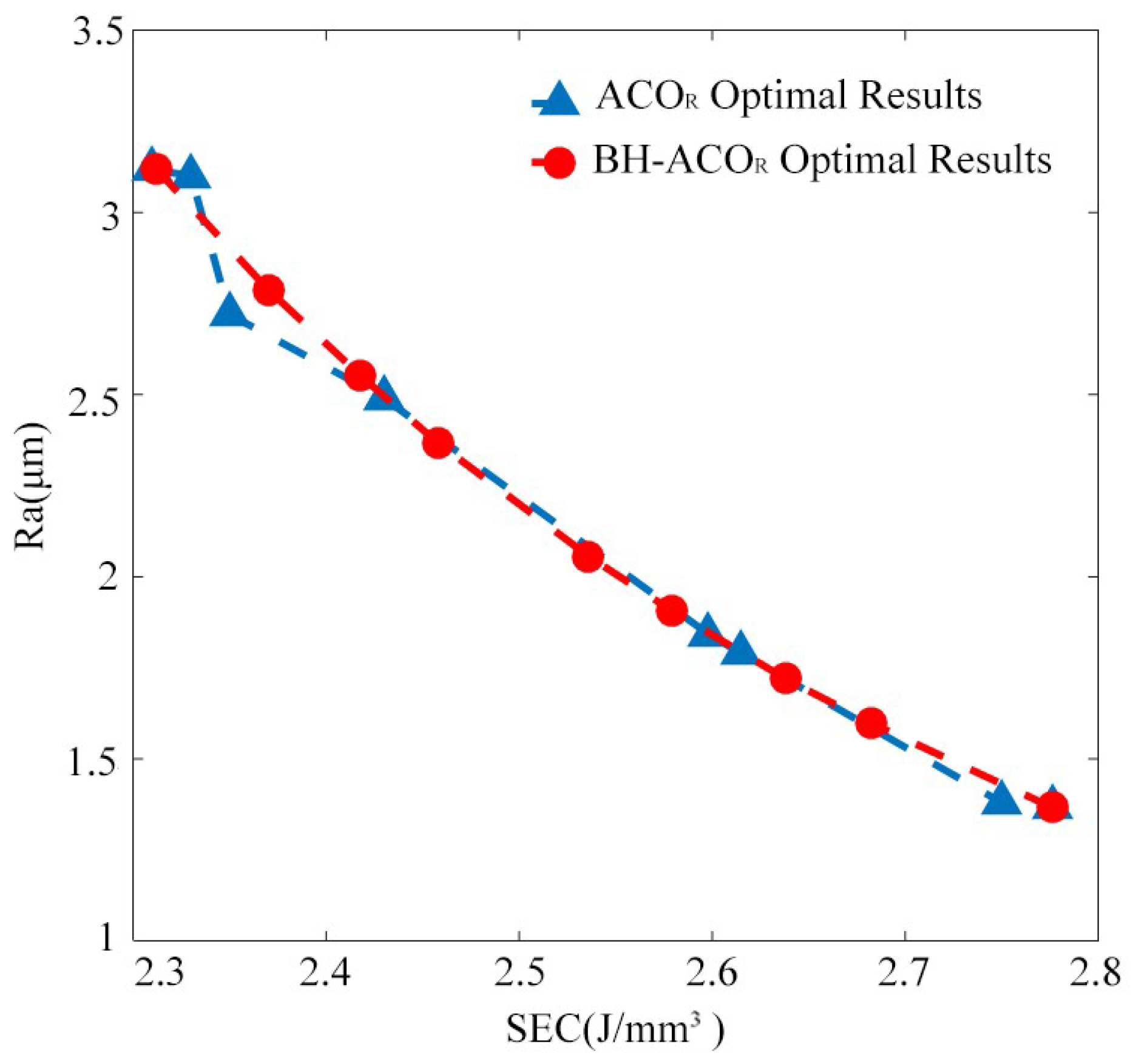
4.1. BH-ACOR Optimization Result

Aiming at the optimization of energy consumption and surface roughness while turning on CNC lathes, an optimization program was written, which is based on the BH-ACOR improved algorithm. It was realized in the Matlab2016a environment. The algorithm’s parameters used in the program are shown in Table 4.
In the case of setting the weight coefficient c of the multi-objective optimization function to 0.5, the variation in the optimized values of the specific turning energy and machined surface roughness with the number of iterations is shown in Figure 7. It can be seen that the algorithm was stably converging when running up to the 50th generation, at which point the corresponding specific turning energy SEC was 2.536 J/mm3 and the machined surface roughness was 2.056 μm. In order to further observe the changes in the turning parameters, the search results of optimal turning parameters when the algorithm was run until the 10th, 30th, and 50th generations are shown in Figure 8. It can be seen that when the algorithm was run up to the 30th generation, the black hole search results exhibited a convergence trend; when it was run up to the 50th generation, the black hole location concentrated near v c = 60 mm/s, f = 0.28 m/s, and a p = 0.7 mm, meaning that the algorithm had converged at this time, constituting the optimal turning parameter combination.
The optimization results regarding turning specific energy and material surface roughness obtained by optimizing the BH-ACOR and ACOR with different weight coefficients c are shown in Table 5.
In order to demonstrate the performance of the algorithm more intuitively, the results yielded by the BH-ACOR and ACOR are shown in Figure 9. From Figure 9, it can be seen that the search result distribution of the ACOR is relatively concentrated. This is because when c takes different values, the distance difference between the solutions obtained by the ACOR algorithm is significant. The search results of the BH-ACOR algorithm are relatively evenly distributed, indicating that the BH-ACOR has to some extent avoided local optimization problems.
In order to further verify the performance of the algorithm proposed in this paper, the BH-ACOR was applied to problems that were optimized in other studies. Table 6 lists the optimization results compared with the algorithms used in different studies. Compared with the results obtained using the orthogonal optimization method adopted by Tian Xiao [19], it was found that the grinding specific energy (SEG) was reduced by 43.39%, and the surface roughness, Ra, was reduced by 4.29%. Although there was little improvement in Ra optimization, the SEG was significantly reduced, meaning that the BH-ACOR can further reduce grinding energy consumption while achieving the same processing quality. Compared with the GA algorithm adopted by Agarwal [20], the algorithm proposed in this paper can optimize all three targets to a certain extent, especially the removal rate MR, which reached 78.1%. Compared with the strengthening Pareto algorithm developed by Zhang [21], the BH-ACOR can acquire basically the same result in terms of surface roughness but can also improve the material removal rate (MRR) by 20.9%.

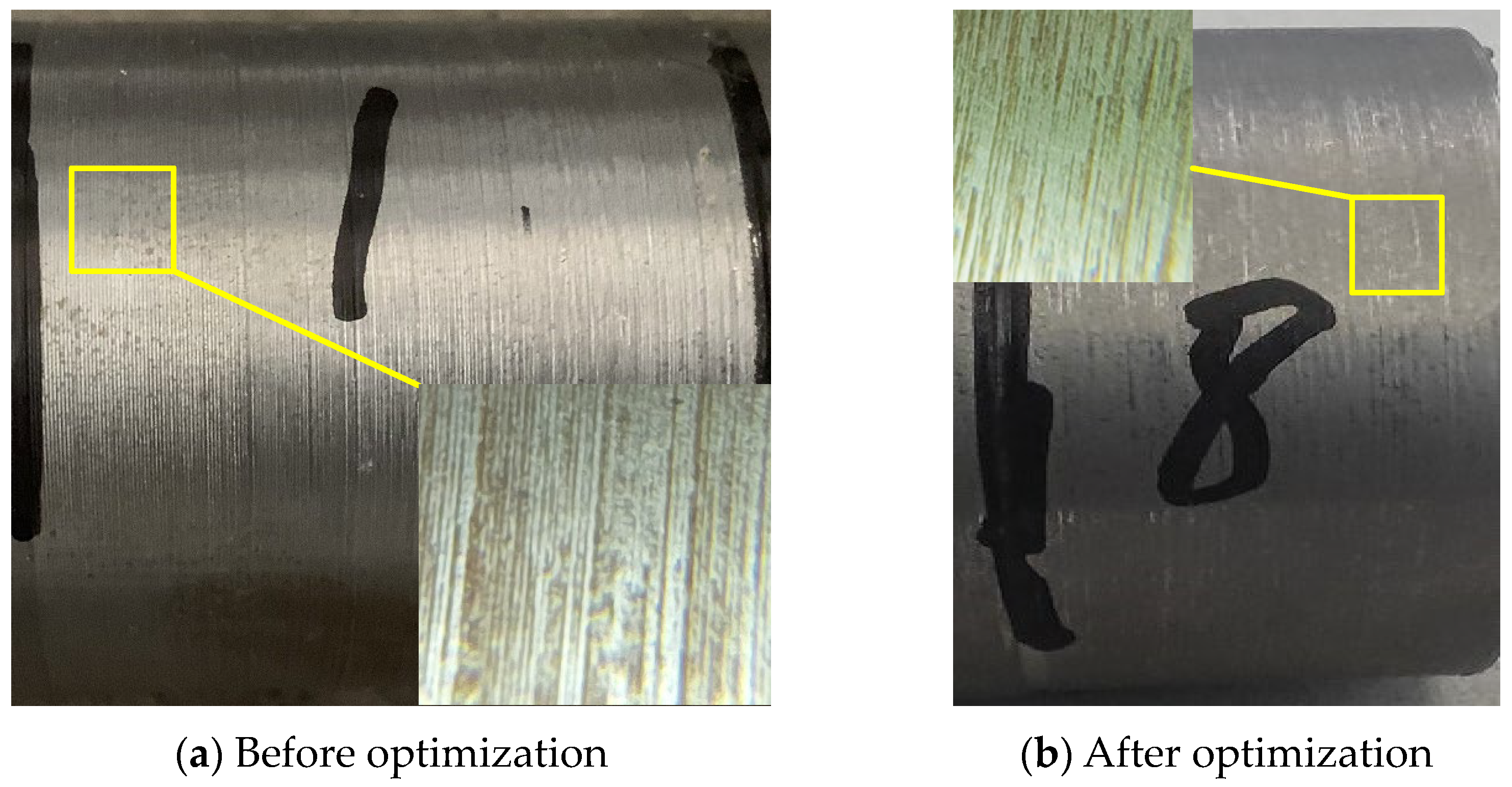
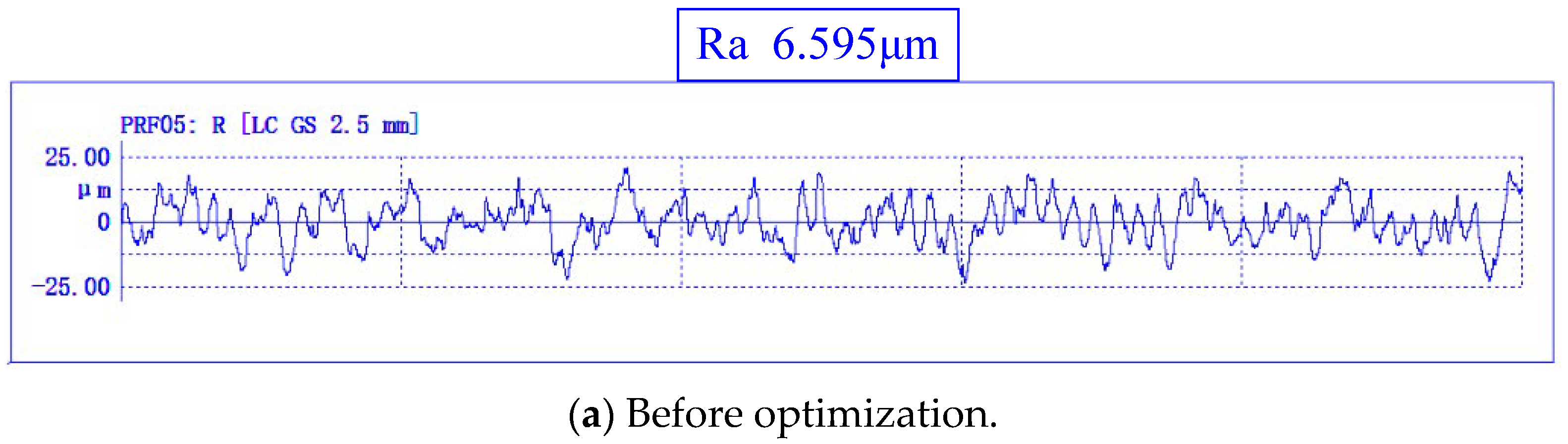
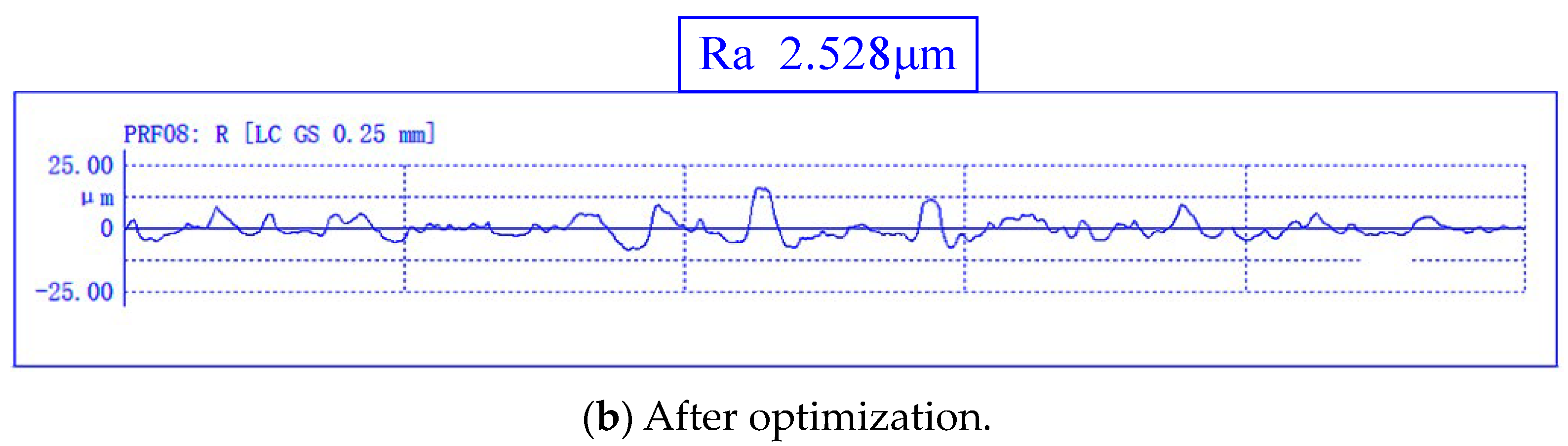
4.2. Result Verification

When c = 0.5, the turning parameters ( v c = 60 mm/s, f = 0.28 m/s, and a p = 0.7 mm) were processed on the test platform, and the corresponding turning specific energy and surface roughness values were obtained and compared with the results obtained by using experience parameters, as shown in Table 7. The surface morphologies obtained using turning 45 steel with the first group of turning parameters before optimization and after optimization are shown in Figure 10a,b, respectively, and the measured workpiece contour curves are shown in Figure 11a,b.
As can be seen from the table, compared with the first four groups of empirical parameter processing, the turning parameters optimized by the BH-ACOR algorithm can improve the specific energy of cutting (SEC) to a certain extent. The SEC obtained by using the optimized turning parameters was 2.69 J/mm3, which is 2.28% higher than the SEC 2.63 J/mm3 of the fifth group, but the surface roughness Ra was reduced from 3.51 μm to 2.53 μm, which is about 27.92% lower.

5. Conclusions

This article aimed to solve the optimal energy consumption and material surface quality in CNC lathe machining and proposed a black hole continuous domain ant colony algorithm to solve the optimal cutting parameters in the lathe-machining process, thereby determining the optimal cutting parameters for CNC lathe material. Compared with the results of other algorithms, it was found that the BH-ACOR performs well in multi-objective optimization problems, and the optimization results are better. Compared with a set of empirical parametric machining results, the SEC was 2.69 J/mm3, which is 2.28% higher, but the surface roughness Ra could be reduced from 3.51 μm to 2.53 μm, which is about 27.92% lower. Therefore, the BH-ACOR can meet the requirements of optimal processing energy consumption under the premise of ensuring material quality and provide effective solutions with which enterprises can optimize processing technology and select the most appropriate processing parameters.

Author Contributions

Conceptualization, J.L., P.H. and H.L.; Data curation, P.H., H.L. and S.L.; Funding acquisition, J.L., L.X. and K.H.; Methodology, J.L.; Writing—original draft, J.L. and P.H.; Writing—review and editing, L.X. All authors have read and agreed to the published version of the manuscript.

Funding

This work was supported by the National Key R&D Program of China (grant number 2018YFB1701205) and the Key Research Projects of Henan Province (grant number 222102220044).

Institutional Review Board Statement

Not applicable.

Informed Consent Statement

Not applicable.

Data Availability Statement

The data presented in this study are available in article.

Conflicts of Interest

The authors declare no conflicts of interest.

References

  1. Li, T.; Kong, L.L.; Zhang, H.C.; Iqbal, A. Research status and development trend of typical cutting machine energy consumption model. J. Mech. Eng. 2014, 50, 102–111. [Google Scholar] [CrossRef]
  2. Gutowski, T.G.; Branham, M.S.; Dahmus, J.B.; Jones, A.; Thiriez, A. Thermodynamic Analysis of Resources Used in Manufacturing Processes. Environ. Sci. Technol. 2009, 43, 1584–1590. [Google Scholar] [CrossRef] [PubMed]
  3. Kara, S.; Li, W. Unit process energy consumption models for material removal processes. CIRP Ann. 2011, 60, 37–40. [Google Scholar] [CrossRef]
  4. Feng, C.H.; Huang, Y.G.; Wu, Y.L.; Zhang, J.Y. Feature-based optimization method integrating sequencing and cutting parameters for minimizing energy consumption of CNC machine tools. Int. J. Adv. Manuf. Technol. 2022, 121, 503–515. [Google Scholar] [CrossRef]
  5. Song, L.; Yan, C.P.; Tu, G.; Xiang, M.H.; Liu, Y.F. Prediction and optimization of surface roughness in high-speed dry milling of 30CrMnSiNiA using GPR and MOHHO algorithm. Int. J. Adv. Manuf. Technol. 2023, 128, 4357–4377. [Google Scholar] [CrossRef]
  6. Li, W.Z.; Zheng, H.; Feng, Y.Z. Optimization of Cutting Parameters for Deep Hole Boring of Ti-6Al-4V Deep Bottle Hole. Materials 2023, 16, 16155286. [Google Scholar] [CrossRef] [PubMed]
  7. Camposeco-Negrete, C.N.J. Sustainable machining as a mean of reducing the environmental impacts related to the energy consumption of the machine tool: A case study of AISI 1045 steel machining. Int. J. Adv. Manuf. Technol. 2019, 102, 27–41. [Google Scholar] [CrossRef]
  8. Su, Z.; Meng, L. Multi-Objective Optimization of Cutting Parameters in Turning AISI 304 Austenitic Stainless Steel. Met. Open Access Metall. J. 2020, 10, 217. [Google Scholar] [CrossRef]
  9. Feng, C.H.; Guo, H.H.; Zhang, J.Y.; Huang, Y.G.; Huang, S. A systematic method of optimization of machining parameters considering energy consumption, machining time, and surface roughness with experimental analysis. Int. J. Adv. Manuf. Technol. 2022, 119, 7383–7401. [Google Scholar] [CrossRef]
  10. Song, L.; Shi, J.; Pan, A.D.; Xie, J. A Dynamic Multi-Swarm Particle Swarm Optimizer for Multi-Objective Optimization of Machining Operations Considering Efficiency and Energy Consumption. Energies 2020, 13, 2616. [Google Scholar] [CrossRef]
  11. Wang, L.P.; Han, J.H.; Ma, F.J.; Li, X.K.; Wang, D. Accuracy design optimization of a CNC grinding machine towards low-carbon manufacturing. J. Clean. Prod. 2023, 406, 137100. [Google Scholar] [CrossRef]
  12. Dorigo, M.; Gambardella, L.M. Ant colony system: A cooperative learning approach to the travelling salesman problem. IEEE Trans Evol. Comput. 1997, 1, 53–66. [Google Scholar] [CrossRef]
  13. Zhou, J. Ship Path Planning and Tracking Control Based on Improved Ant Colony Algorithm. Master’s Thesis, Dalian Maritime University, Dalian, China, 2021. Volume 17. [Google Scholar]
  14. Jin, T.T.; Wu, S.F.; Li, S.; Wang, T.F. Research on improved continuous domain ant colony algorithm for girder lightweight. Mech. Des. Manuf. Eng. 2019, 48, 13–17. [Google Scholar]
  15. Xu, W.J.; Wang, X.H.; Xiao, J.M.; Gu, J.Y. gravitational search algorithm based on improved adaptive black hole mechanism. Comput. Appl. Res. 2022, 39, 3046–3054. [Google Scholar]
  16. Zhao, G.Y.; Li, C.X.; Tian, Y.Z.; Zhang, J.F.; Zhao, G.X. Prediction Model for Net Cutting Specific Energy in CNC Turning. J. Nanjing Univ. Aeronaut. Astronaut. Engl. Version 2020, 37, 385–392. [Google Scholar]
  17. Cui, F. Research on Optimization Method of NC Turning Parameters for Low Energy Consumption and High Surface Quality. Master’s Thesis, Yanbian University, Jilin, China, 2018; pp. 19–20. [Google Scholar]
  18. Hatamlou, A. Black hole: A new heuristic optimization approach for data clustering. Inf. Sci. 2013, 222, 175–184. [Google Scholar] [CrossRef]
  19. Tian, X. Experimental study on energy consumption and surface quality of superfine cemented carbide grinding process. Fujian Fujian Inst. Eng. 2020, 51, 50–55. [Google Scholar]
  20. Agarwal, S. Optimizing machining parameters to combine high productivity with high surface integrity in grinding Silicon Carbide Ceramics. Ceram. Int. 2016, 42, 6244–6262. [Google Scholar] [CrossRef]
  21. Zhang, Y.; Li, B.; Yang, J. Modeling and optimization of alloy steel 20CrMnTi grinding process parameters based on experiment investigation. Int. J. Adv. Manuf. Technol. 2018, 95, 1859–1873. [Google Scholar] [CrossRef]
Figure 1. Power compositions of each stage of machine tool processing.
Applsci 14 00905 g001
Figure 2. Test platform for active power measurement.
Applsci 14 00905 g002
Figure 3. Power curve during machining.
Applsci 14 00905 g003
Figure 4. Surface-roughness-measuring instrument.
Applsci 14 00905 g004
Figure 5. Comparison of fitted results.
Applsci 14 00905 g005
Figure 6. BH-ACOR algorithm flow chart.
Applsci 14 00905 g006
Figure 7. Change curve of optimization results of turning process.
Applsci 14 00905 g007
Figure 8. Search results of turning parameters for different iterations.
Applsci 14 00905 g008
Figure 9. Comparison of optimization results between BH-ACOR and ACOR.
Applsci 14 00905 g009
Figure 10. Comparison of surface morphology before and after optimization.
Applsci 14 00905 g010
Figure 11. Optimization of the front and rear workpiece contour curves.
Applsci 14 00905 g011aApplsci 14 00905 g011b
Table 1. Turning parameter levels.
FactorsLevel
v c (m/min)405060
f (mm/r)0.20.30.4
a p (mm)0.30.50.7
Table 2. Turning test data.
Order Number v c
(m/min)
f
(mm/r)
a p
(mm)
P c
(W)
MRR
(mm3/s)
SEC
(J/mm3)
Ra
(μm)
1400.20.3152.340.003.813.18
2400.30.5325.2100.003.254.25
3400.40.7533.3186.672.876.19
4500.20.5268.883.333.232.07
5500.30.7471.4175.002.692.84
6500.40.3278.5100.002.794.59
7600.20.7386.6140.002.761.34
8600.30.3238.390.002.651.87
9600.40.5504.2200.002.523.61
Table 3. Verification results for turning test.
Order Number v c
(m/min)
f
(mm/r)
a p (mm)Pc
(W)
SEC Fitted
(J/mm3)
SEC Actual Value
(J/mm3)
Ra Fitted
(μm)
Ra Actual Value
(μm)
1400.30.74753.123.394.344.61
2400.40.53772.992.836.296.63
3500.40.54612.652.774.354.14
4500.20.73363.072.881.851.77
5600.40.76782.312.423.123.01
Table 4. BH-ACOR algorithm parameter settings.
ParameterValueParameterValue
Iterations200 v c max 60
Initial population k10 f min 0.2
Reinforcement factor q 0.5 f max 0.4
Offset distance ratio ξ 0.8 a p max 0.3
v c min 40 a p min 0.7
Table 5. Optimization results of turning under different weights.
BH-ACORACOR
cSEC (J/mm3)Ra (μm)SEC (J/mm3)Ra (μm)
0.12.7761.3672.7751.366
0.22.6821.5252.7761.367
0.32.6381.6022.7521.382
0.42.5791.7782.6151.792
0.52.5361.9562.5981.843
0.62.4582.2822.4312.491
0.72.4182.6652.3522.721
0.82.3702.8922.3323.101
0.92.3123.1192.3113.119
Table 6. Comparison of BH-ACOR optimization results with those for different algorithms.
AuthorOriginal ResultBH-ACOR Result
Tian xiao
[19]
v w (mm/s)
48
v s (m/s)
30
ap (μm)
5
v w (mm/s)
22.15
v s (m/s)
30
ap (μm)
20
SEG (J/mm3)
70.13
Ra (μm)
0.63
SEG (J/mm3)
39.7↓
Ra (μm)
0.603↓
Agarwal
[20]
ap (μm)
45
v w (m/min)
7.86
G (μm)
121
Ra (μm)
75
ap (μm)
45
v w (m/min)
14
G (μm)
5.02
Ra (μm)
125
MR (mm3/min)
−353.7
Ra (μm)
0.335
%D
3.5
MR (mm3/min)
−630↓
Ra (μm)
0.21↓
%D
2.65↓
Zhang
[21]
v w (m/s)
120
v s (m/s)
0.836
ap (mm)
13.5
v w (m/s)
150
v s (m/s)
0.719
ap (mm)
19
MRR (mm3/s)
−11.286
Ra (μm)
0.686
MRR (mm3/s)
−13.65↓
Ra (μm)
0.684↓
Among them, "↓" indicates that the result is smaller than before optimization, indicating a better optimization effect.
Table 7. Comparison before and after optimization.
v c
(m/min)
f
(mm/r)
a p
(mm)
P c
(W)
SEC
(J/mm3)
Ra
(μm)
Before400.40.53842.886.60
400.30.74773.414.74
500.40.54102.464.38
500.30.53712.973.43
600.40.33162.633.51
After600.280.75272.692.53
Disclaimer/Publisher’s Note: The statements, opinions and data contained in all publications are solely those of the individual author(s) and contributor(s) and not of MDPI and/or the editor(s). MDPI and/or the editor(s) disclaim responsibility for any injury to people or property resulting from any ideas, methods, instructions or products referred to in the content.

