
Analysis of Bridge Tests on Sandy Overburden Site with Fault Dislocating

Abstract
1. Introduction
2. Experimental Plan Design
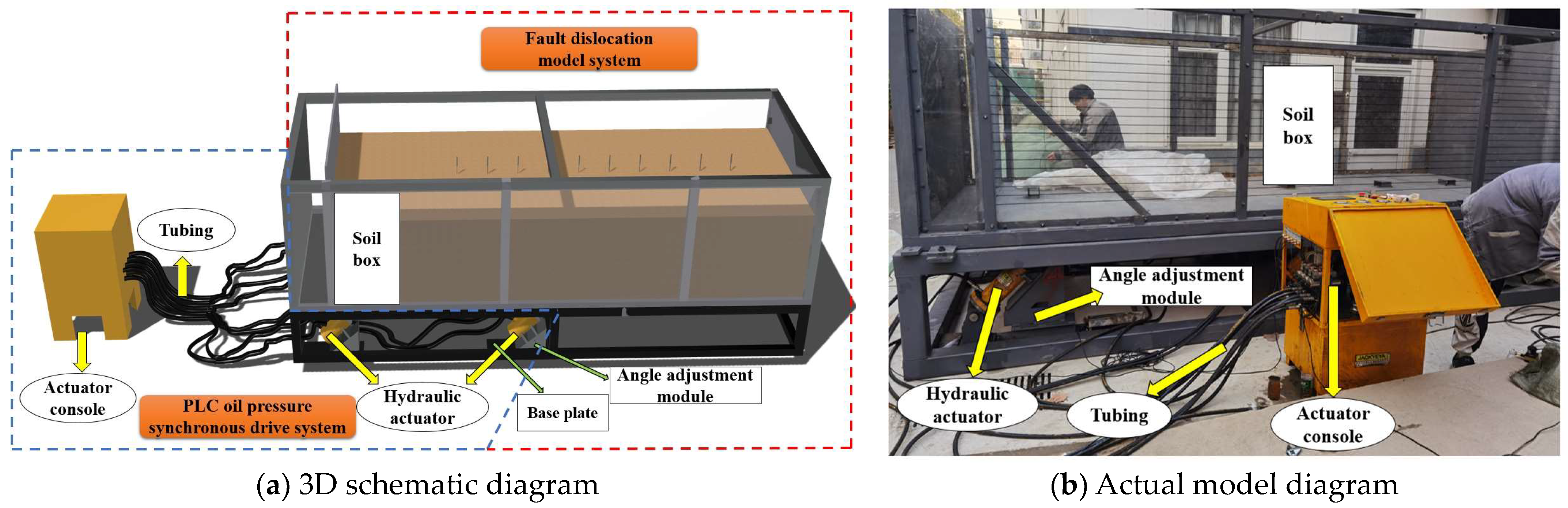
2.1. Bedrock Dislocation Loading Test System
2.2. Similarity Relationship
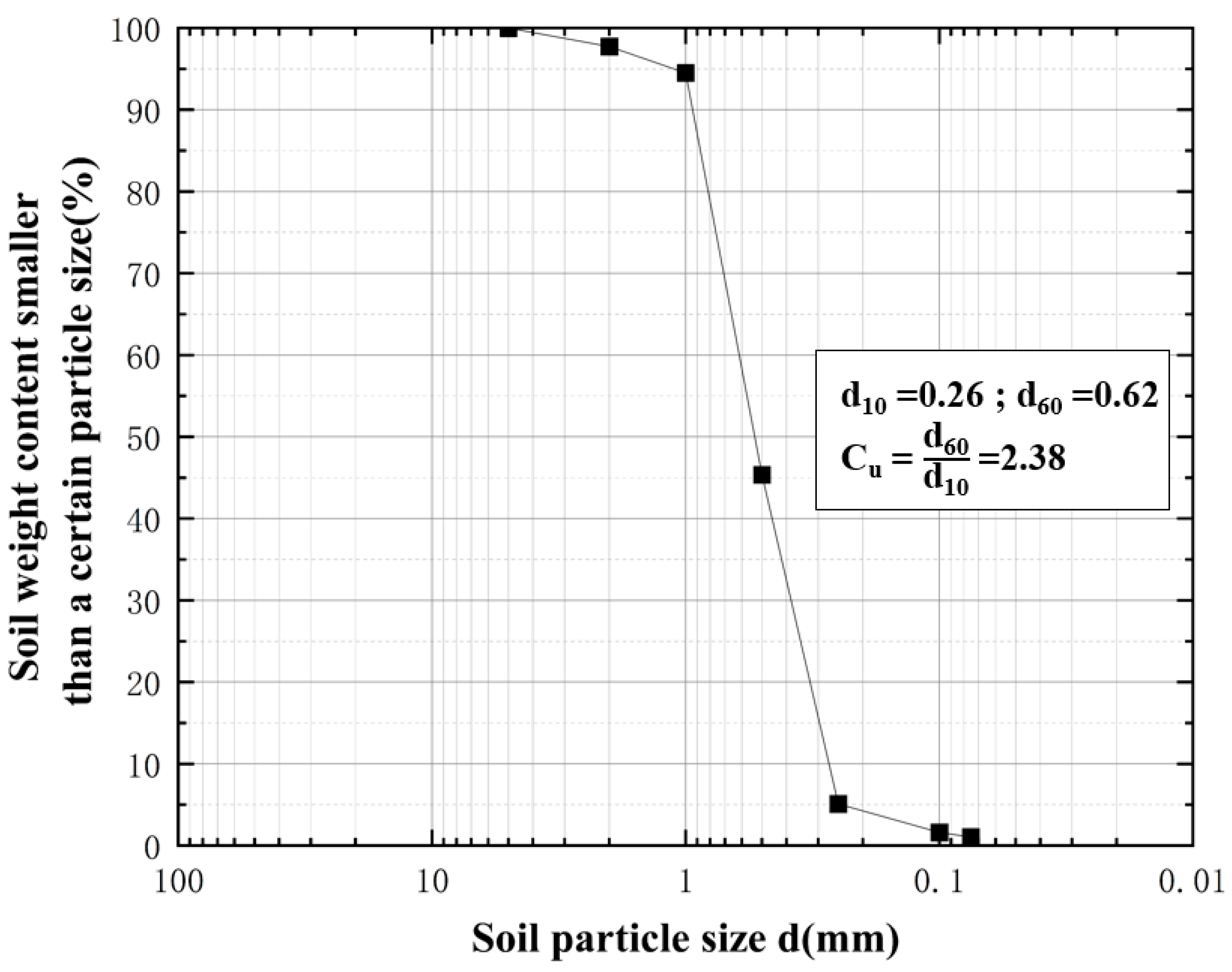
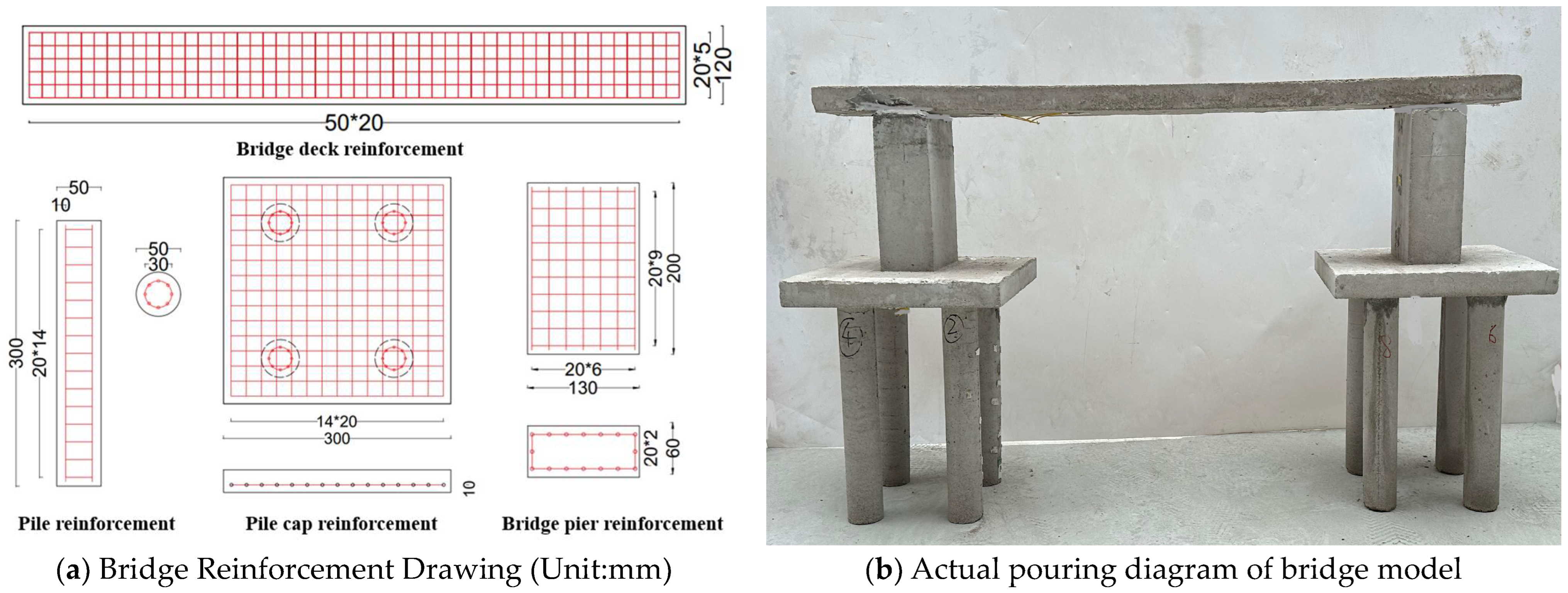
2.3. Bridge Model and Soil Compaction
2.4. Experimental Plan Design
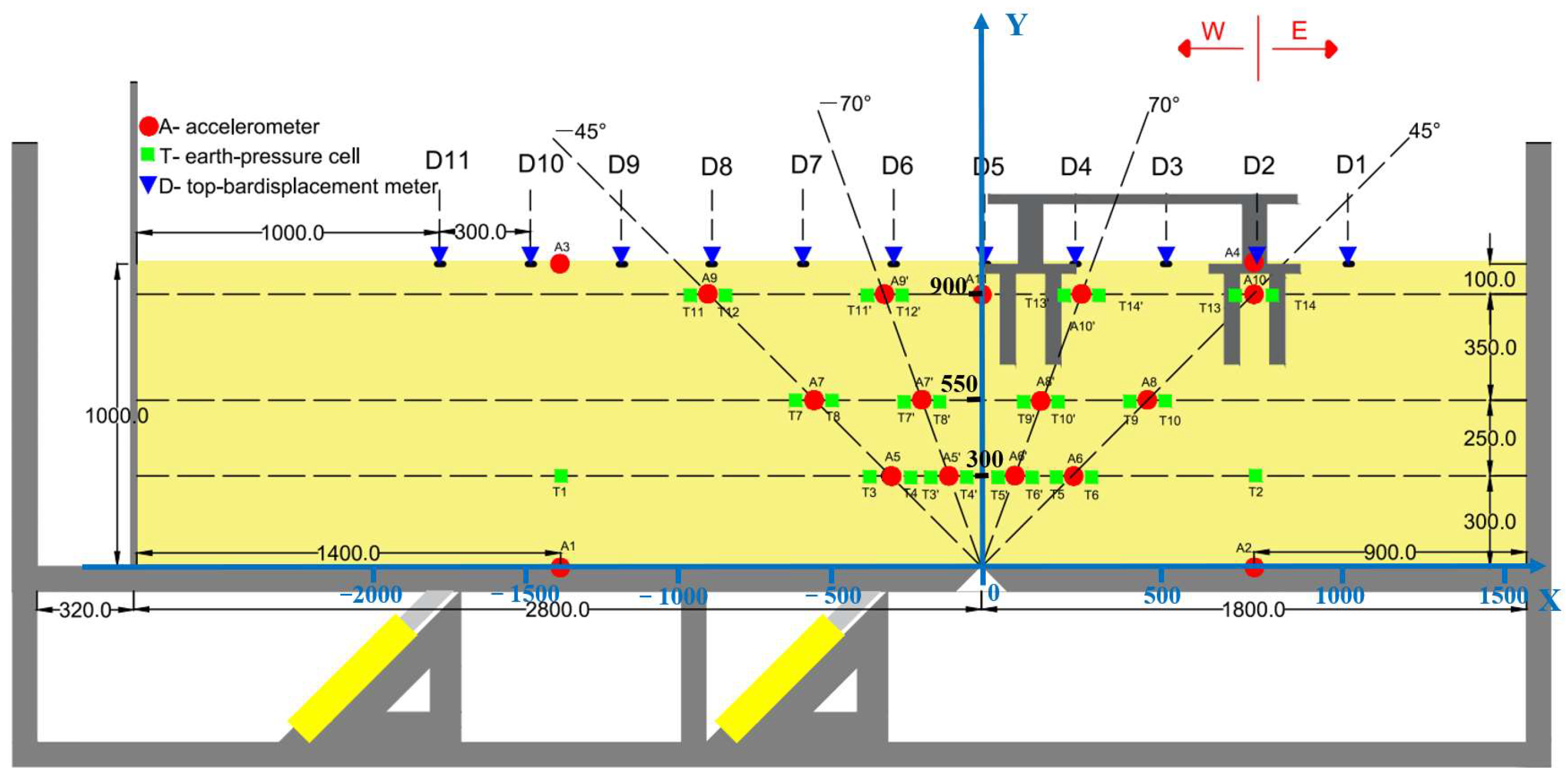
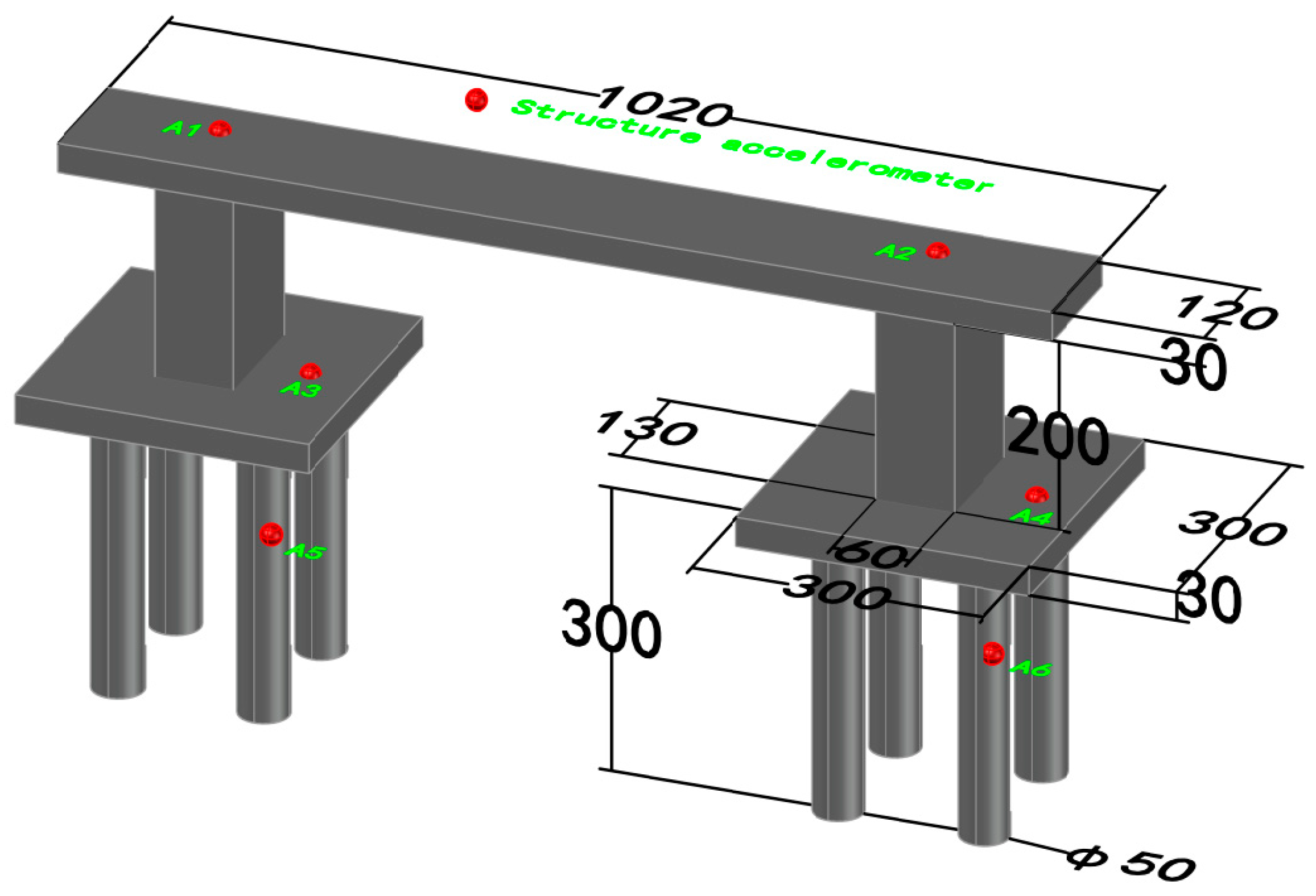
2.5. Monitoring Point Layout
3. Analysis of Test Results
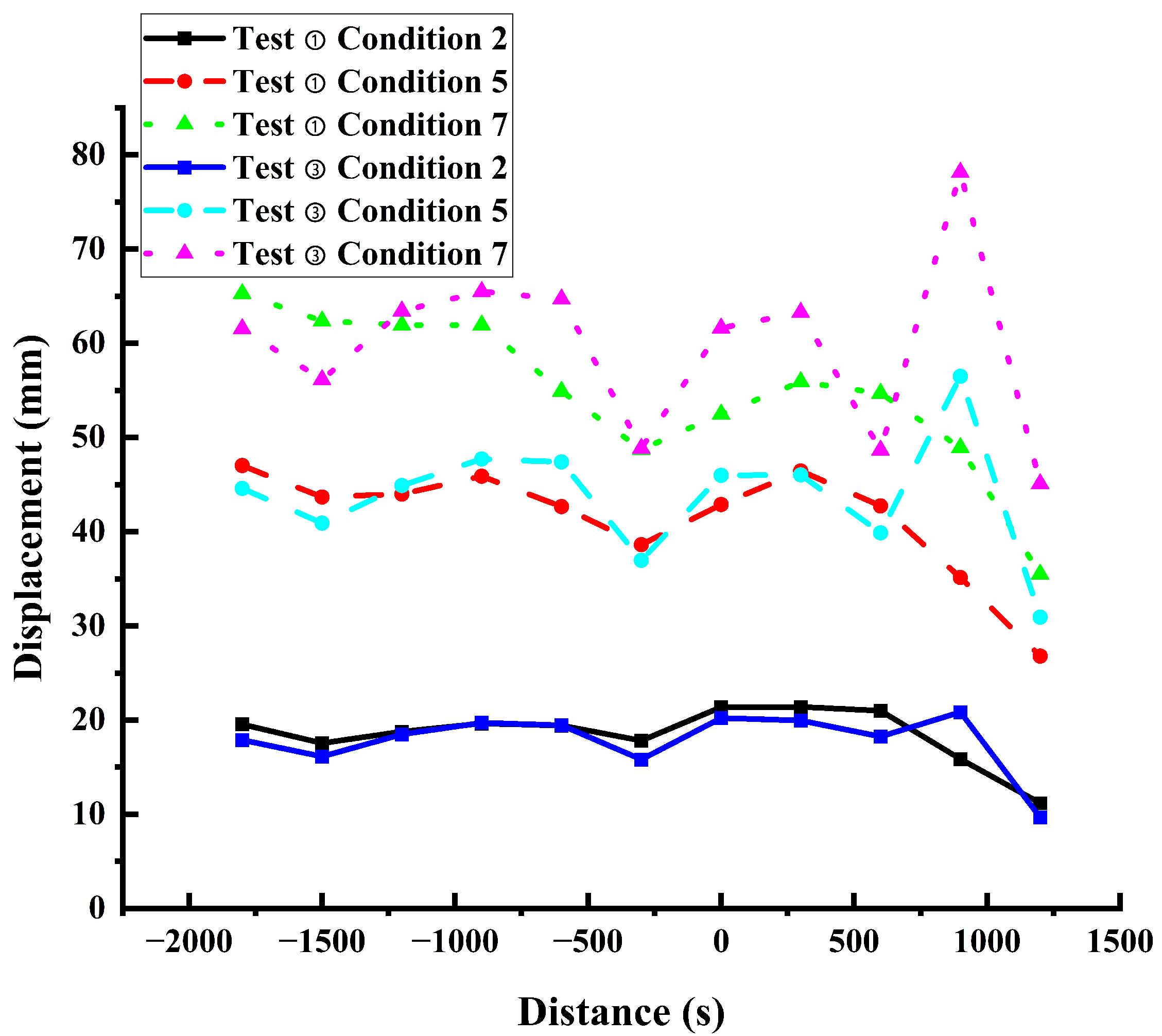
3.1. Comparison of Bridge Sites with Reverse Fault 45° Inclination Angle Sand soil Cover Layer
3.2. Comparison of Bridge Sites with 70° Dip Angle Sand Soil Cover Layer on Normal Fault
4. Mechanism of Foundation Failure in Cross Fault Bridge Sites
- (1)
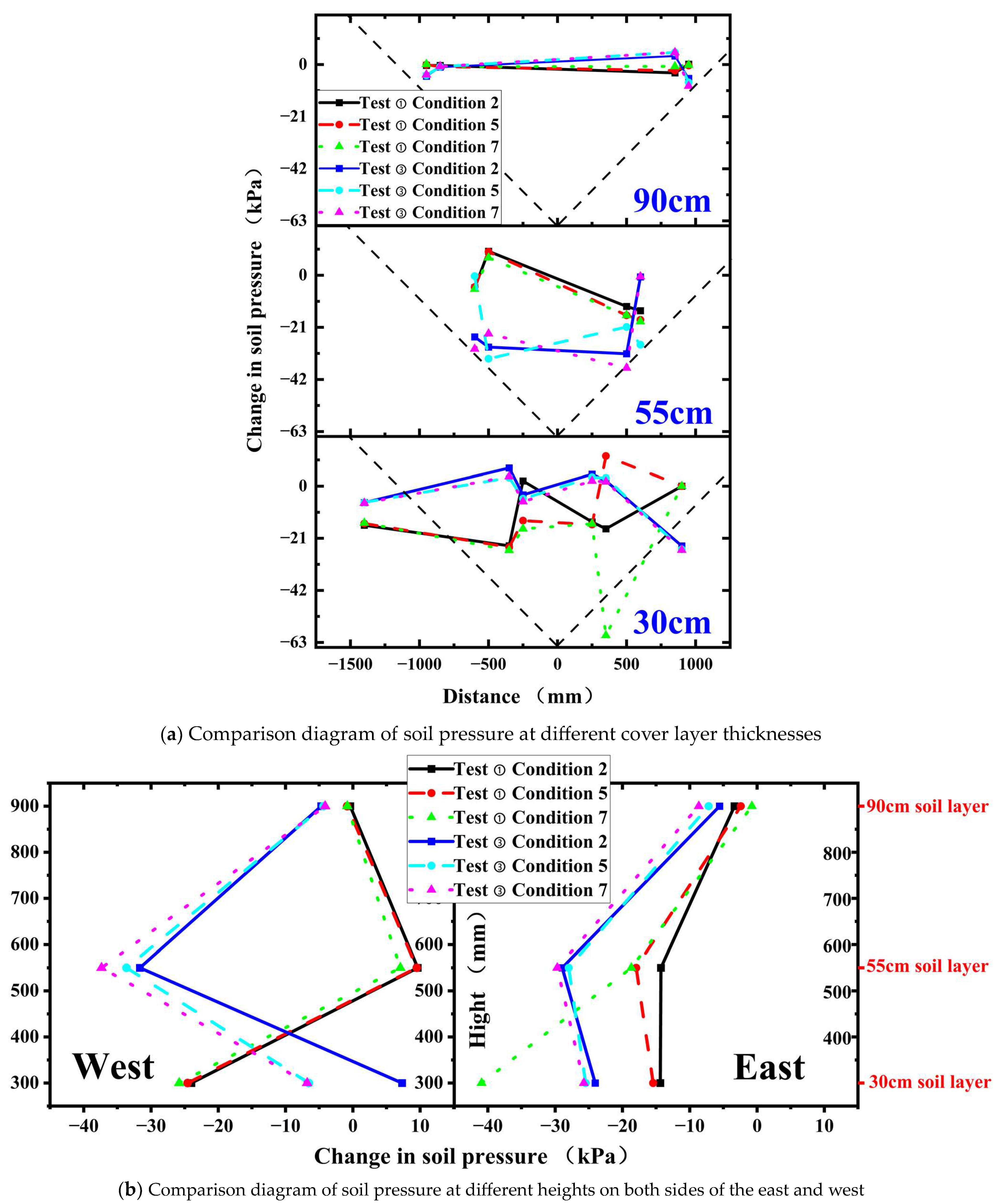
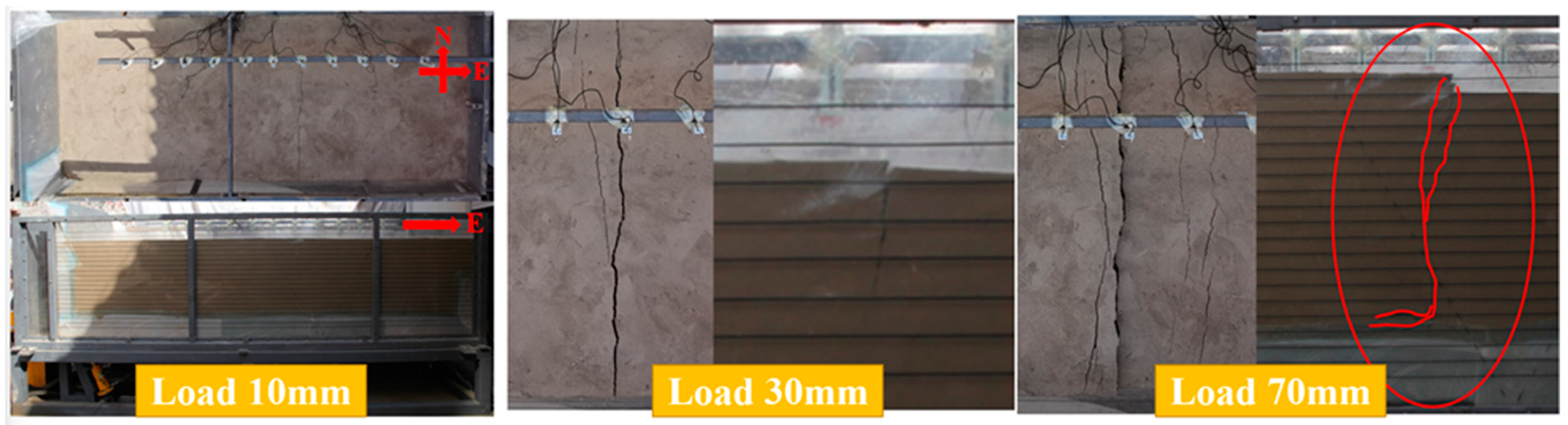
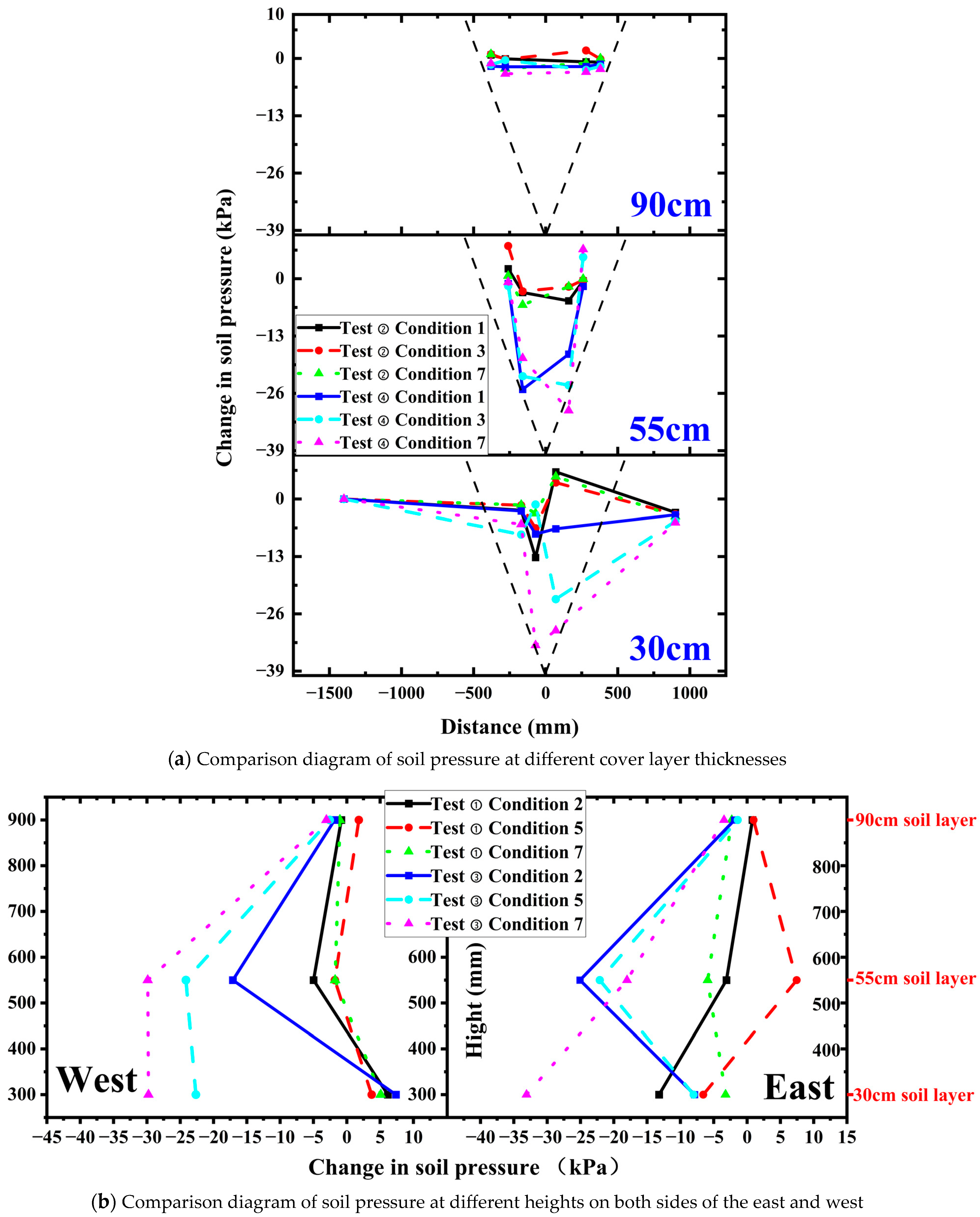
- When bedrock dislocates in a low-dip reverse fault, an extrusion-type shear rupture zone forms within the soil body. This zone extends from the dislocation point toward the dip angle direction, causing raised surface rupture zones. The bridge site’s rupture zones pass through the bridge pile foundations along the fault’s dip direction, offsetting relative to the free site. Due to the substantial stiffness of the bridge structure, soil and bridge interact, causing structural vibration energy to radiate into the soil layer, inducing a damping effect. This interaction results in larger soil pressure around the structure during rupture, influencing a broader range at the bridge site. It affects the middle of the soil layer from depth, highlighting a more noticeable soil amplification effect.
- (2)
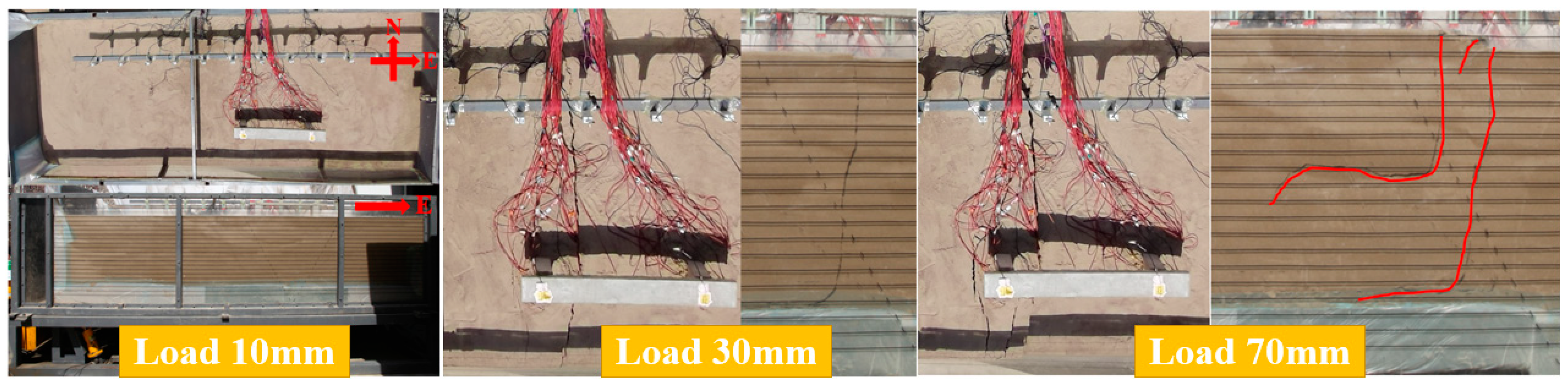
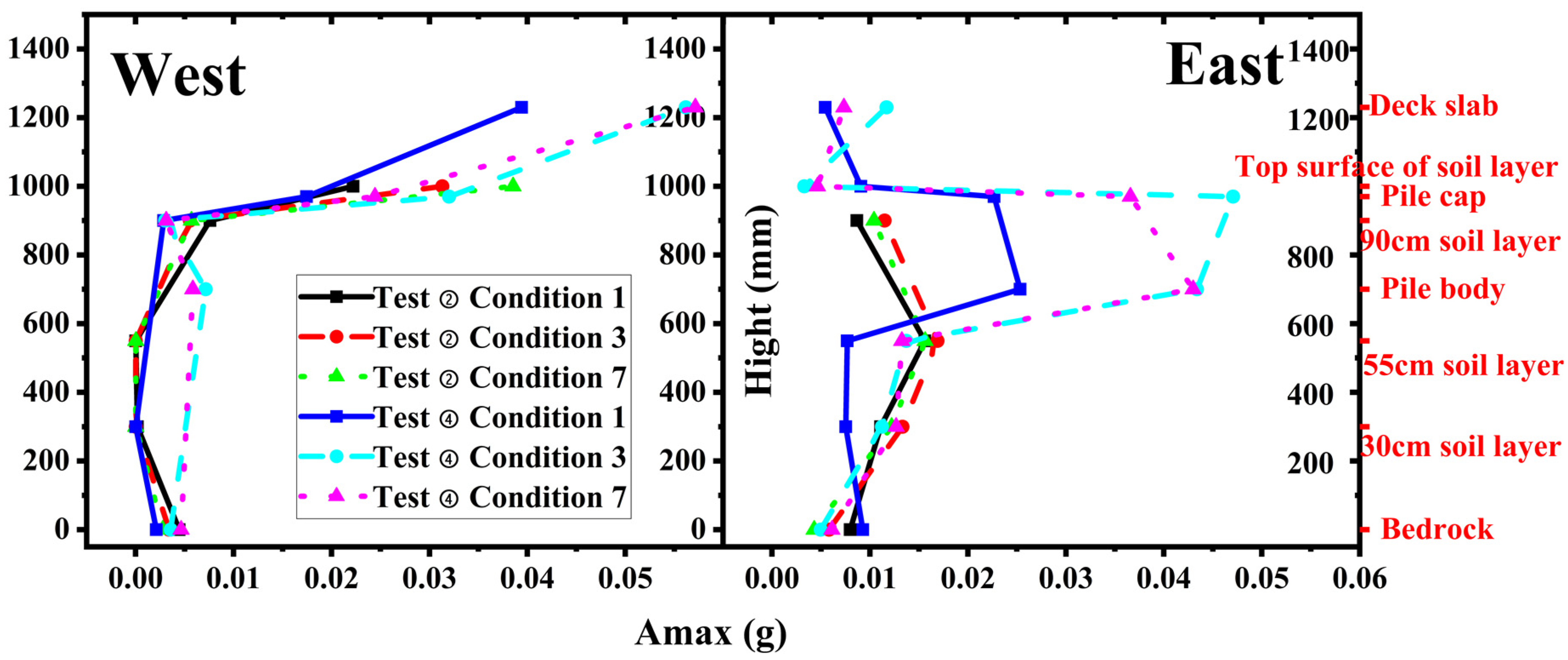
- In the context of high-dip normal fault bedrock dislocation, a tensile shear rupture zone forms within the soil body, centered on the bedrock’s dislocation point. Cracks appear on the ground surface even with minimal bedrock dislocation, and increased dislocation leads to the derivation of multiple surface rupture zones. Simultaneously, the bridge site’s rupture zone passes through the bridge pile foundations along the fault’s dip direction, offsetting relative to the free site. Due to soil interaction with the pile and bearing platform of the bridge structure, soil pressure widens in scope and depth. Soil pressure changes in the middle and lower parts of the soil body become obvious, affecting deeper surface rupture cracks in the overburdened soil layer. Acceleration of the soil layer in the upper disk is about four times greater than in the lower disk, with a more pronounced effect on the upper disk.
- (3)
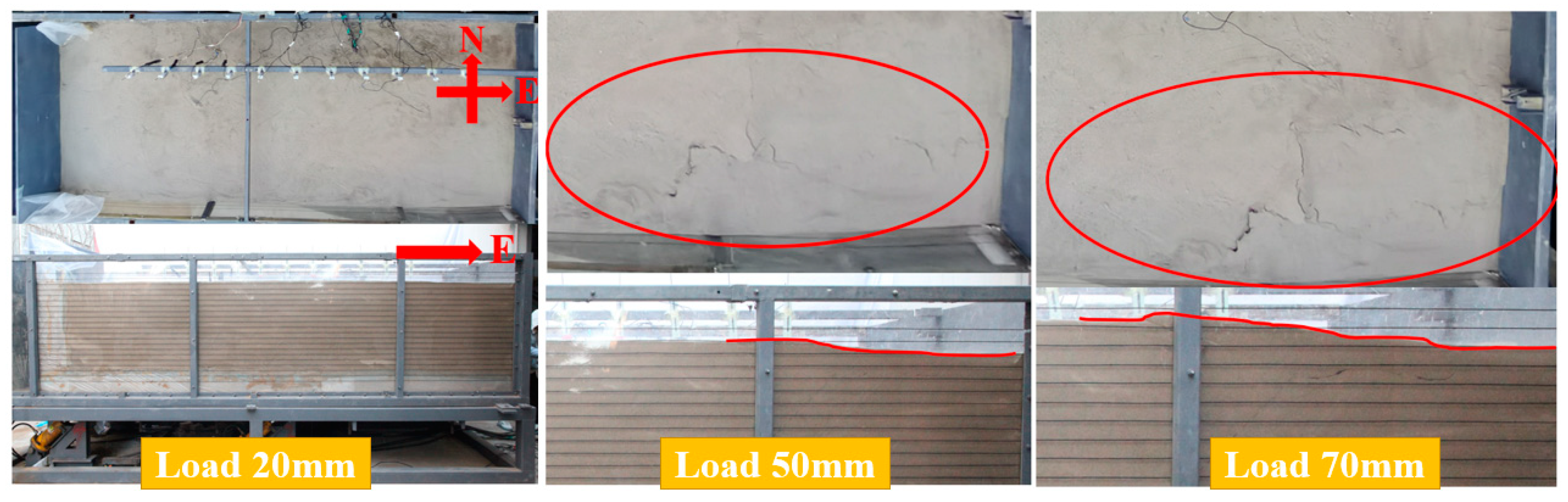
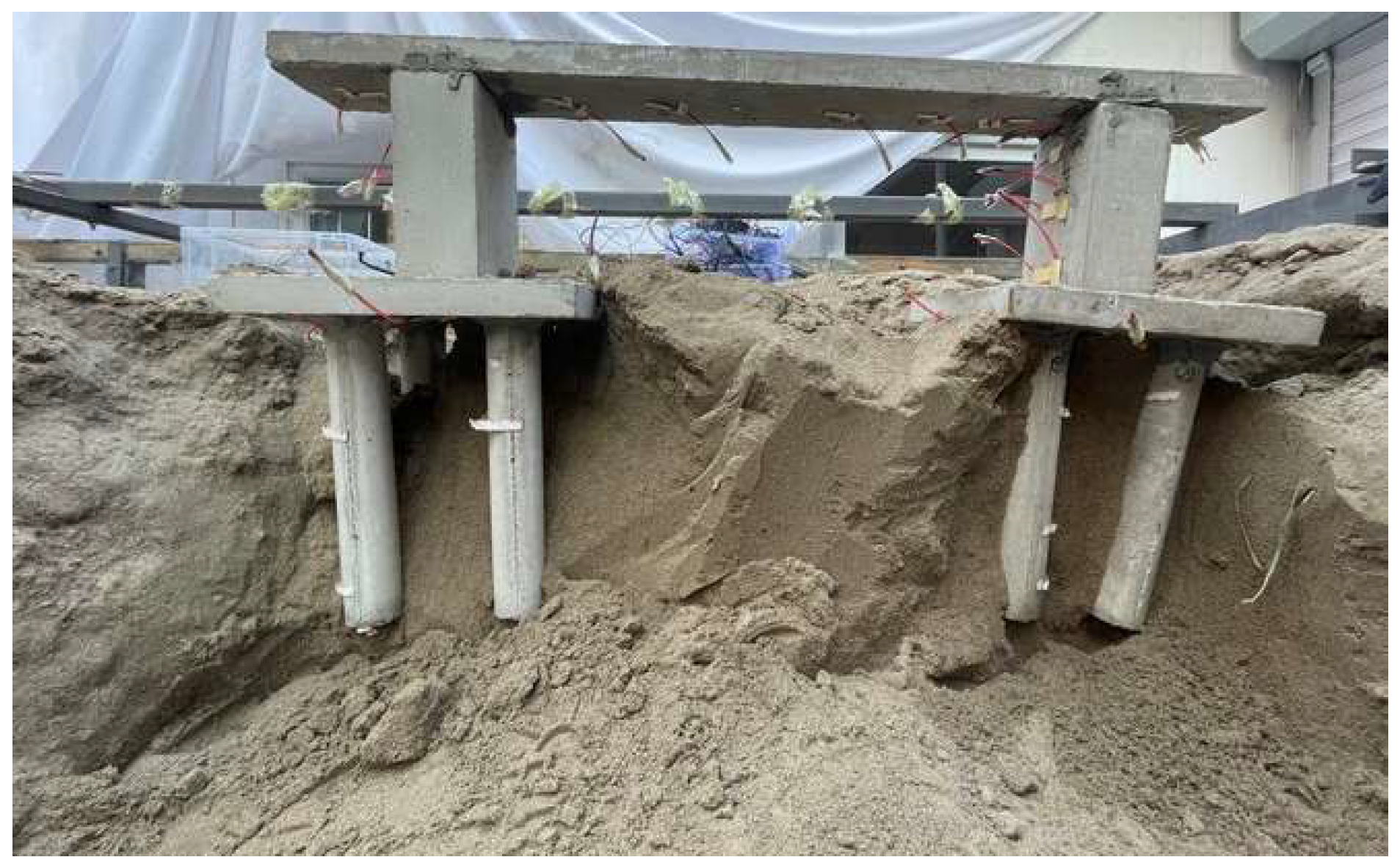
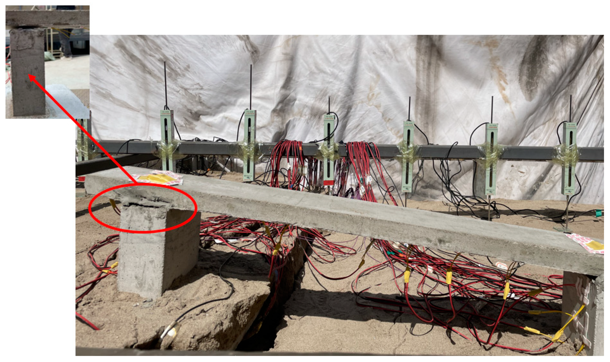
- In sandy soil cover sites, under low-dip reverse fault dislocation, the foundation damage area is lighter than in high-dip positive fault scenarios, both on the surface and within the soil body. The pile foundation in the main rupture zone’s concentrated area on the surface experiences greater stress from surface rupture traces, resulting in severe damage and deformation of the pile foundation, the bottom of the bridge deck slab, and the abutment connection.
- (4)
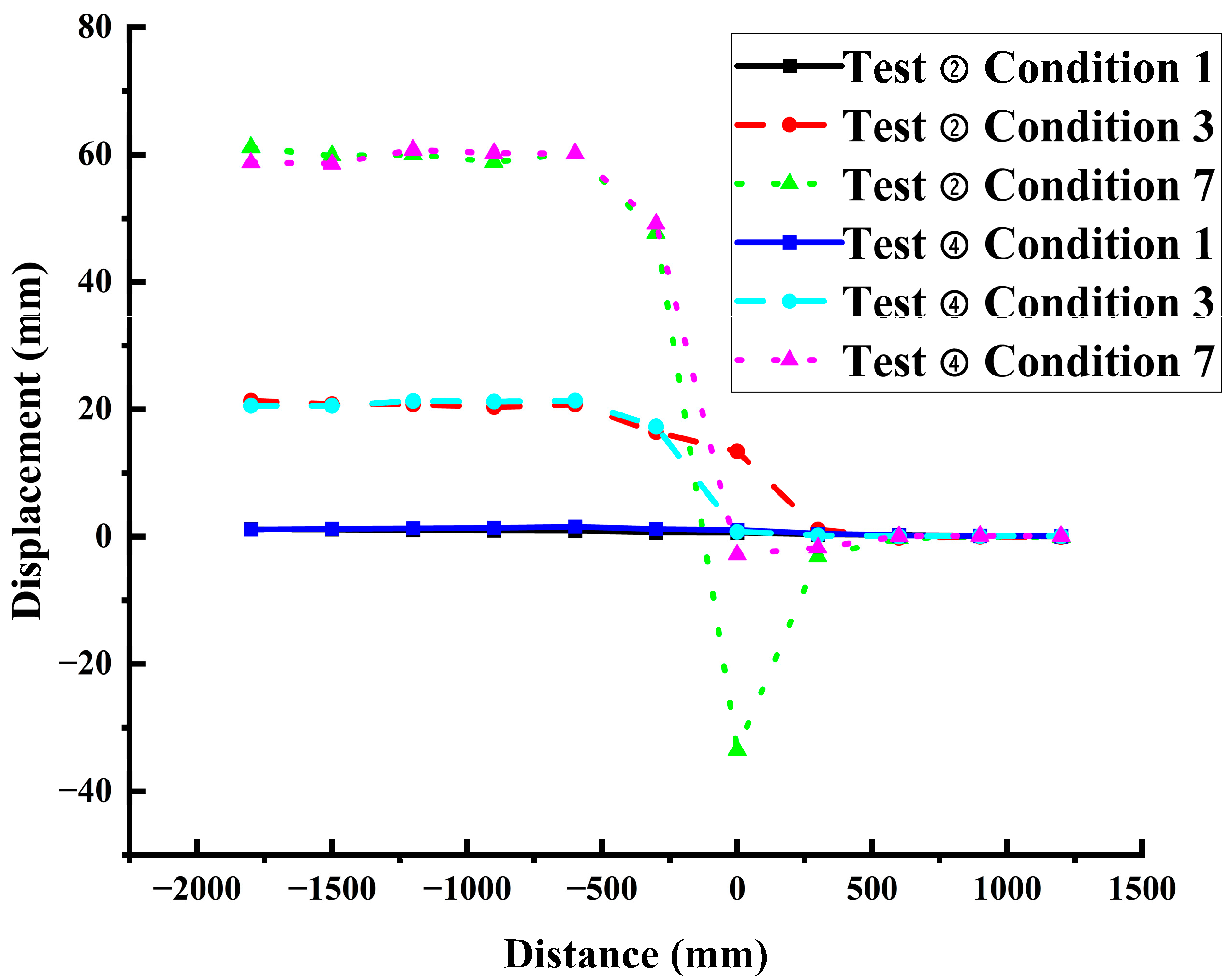
- In the main rupture zone at the surface, the bridge site exhibits a width approximately half that of its corresponding free-field for both low-dip reverse fault and high-dip normal fault dislocations. Regarding rupture traces within the site soils (profile), the width of these traces at the bridge site is smaller than the free-field variant in the case of low-dip reverse fault dislocations. Conversely, under high-dip normal fault conditions, the width of the bridge site’s soil rupture traces is about 4.8 times larger than the free-field variant, reaching 72 m.
- (5)
- Concerning the avoidance distance, the bridge site has a smaller avoidance value compared to the free field for both low-dip reverse fault and high-dip normal fault dislocations. Regarding maximum surface deformation, the value is slightly larger for the bridge site under low-dip reverse fault dislocation and smaller for the bridge site under high-dip normal fault dislocation, compared to the free field.
- (6)
- The avoidance distance of the bridge site across the fault can be appropriately reduced based on free-field conditions. When the bridge site cannot avoid the surface rupture zone resulting from seismic rupture, a simply supported girder bridge can be selected within the avoidance distance, considering the characteristics of the bridge structure itself. Simultaneously, the site and bridge components can be strengthened to accommodate different dislocations. Alternatively, one may contemplate incorporating near-fault ground vibration records for the seismic analysis and design of bridges spanning faults [5]. Adhering to the “Guidelines for Seismic Design of Highway Bridges”, it is recommended to ensure a foundation cover layer thickness of at least 60 m. For bridges falling below category A, opting for structures with smaller spans facilitates easier repairs. In cases where avoiding the development of seismic rupture on the earth’s surface is not feasible, consider aligning all piers within the fault on the same disc, preferably the lower disc, of the foundation [15], and so forth.
5. Conclusions
- (1)
- When a low-dip reverse fault is dislocated, an extruded shear rupture zone forms within the soil body. The presence of the bridge causes the surface rupture zone to shift to the passive disk, reducing the length and width of the rupture zone. With increasing bedrock dislocation, the range of surface deformation in the free site becomes wider, approximately 1.5 times that of the bridge site. However, the surface deformation and inclination within the bridge site are greater, about three times that in the free site. Earth pressure changes are evident only at the bottom of the soil cover in the free site, while in the bridge site, the influence of earth pressure extends more widely. The acceleration change of the soil body on the bridge site is more pronounced, especially on the top surface, where the acceleration is about four times larger than that in the center and at the bottom.
- (2)
- Under the high dip angle positive fault sandy soil cover site, a tensile shear rupture zone forms within the soil body. Due to significant changes in soil pressure at the bridge site in the middle and lower depths of the soil cover, the rupture zone at the bridge site deviates through the bridge pile foundation along the dip angle direction of the fault relative to the free site. The bridge deck plate exhibits bending deformation, and the connection with the bridge abutment shows significant damage. The acceleration of the soil layer on the upper disk is about four times more than that of the lower disk, with a more noticeable effect on the upper disk.
- (3)
- Based on the observed test phenomena and similarity ratios reflecting actual bridge project sites, we propose that, within the surface rupture zone and avoidance distance range, a simply supported beam can be used for “fuse” design and connected with both sides of the bridge for structural “disconnection”. Design parameters such as surface rupture zone and maximum deformation of the bridge site can be inferred from its free site. For example, irrespective of whether it is a low-dip reverse fault or a high-dip positive fault dislocation, the width of the bridge site is smaller than its corresponding free site, approximately half of the free site.
- (4)
- During the construction of bridges across or near faults on sand-covered sites, although the presence of bridges reduces the avoidance distance and maximum surface deformation to a certain extent, it is essential to implement reinforcement measures for the soils at the bridge-bearing platforms and piles within the main rupture zones at the surface. Simultaneously, specialized structural treatments should be applied to the pile-pedestal and bridge deck-pier joints to enhance fracture resistance in the presence of fault dislocations.
- (5)
- As the construction of bridges across faults and existing bridges facing the risk of surface rupture from strong earthquakes rises, the shift from “avoidance” to “rupture resistance” is increasingly urgent. Challenges include insufficient investigation of seismic damage data for bridges in strong earthquake rupture zones and uncertainty regarding the rupture mechanism of overburdened rock and soil layers under bridges. Therefore, further development of a large-scale modeling test loading device for bridges across faults is necessary. Conducting numerous modeling tests on rupture mechanisms in the immediate vicinity of bridges in rupture zones under various experimental conditions is crucial. This approach facilitates proposing reasonable rupture-resistant reinforcement measures, providing a vital basis and data for studying rupture resistance at bridge sites.
Author Contributions
Funding
Institutional Review Board Statement
Informed Consent Statement
Data Availability Statement
Acknowledgments
Conflicts of Interest
References
- Zhang, J.; Bo, J.; Yuan, Y.; Huang, J. Review of research on active fault and its setback. J. Nat. Disasters 2012, 21, 9–18. [Google Scholar]
- Anastasopoulos, I.; Gerolymos, N.; Bransby, G.G.F. Simplified approach for design of raft foundations against fault rupture. Part II: Soil-structure interaction. Earthq. Eng. Eng. Vib. 2008, 7, 165–179. [Google Scholar]
- Ghafari, M.; Nahazanan, H.; Yusoff, Z.; Nik Daud, N.N. A Novel Experimental Study on the Effects of Soil and Faults’ Properties on Tunnels Induced by Normal and Reverse Faults. Appl. Sci. 2020, 10, 3969. [Google Scholar] [CrossRef]
- Irikura, K. Strong Motion Prediction for Inland Crustal Earthquakes Based on Active Fault Survey. Quat. Int. 2012, 279–280, 216. [Google Scholar]
- Hui, Y.; Tai, Y.; Wang, K.; Zhang, S. Discussion about earthquake resistance of the bridges crossing the active fault. China Earthq. Eng. J. 2017, 39, 7. [Google Scholar]
- O’Rourke, T.D.; Palmer, M.C. The Northridge, California earthquake of January 17, 1994: Perfomance of gas transmission pipelines. Nceer Bull. 1994, 79, 94-0011. [Google Scholar]
- Kawashima, K. Damage of bridges resulting from fault rupture in the 1999 Kocaeli and Duzce, Turkey earthquakes and the 1999 Chi-Chi, Taiwan earthquake. Struct. Eng./Earthq. Eng. 2001, 1, 171–190. [Google Scholar]
- Becker, D.; Earthquake Engineering Research Institute. The 1999 Turkey Earthquakes: Bridge Performance and Remedial Actions; Earthquake Engineering Research Institute (EERI): Oakland, CA, USA, 2003. [Google Scholar]
- Chang, K. Seismic Performance of Highway Bridges. Earthq. Eng. Eng. Seismol. 2000, 2, 157–166. [Google Scholar]
- Fan, L.; Hui, Y.; Liu, J.; Zhou, T. Analysis of the Effect of Lateral Collision on the Seismic Response of Bridges under Fault Misalignment. Appl. Sci 2023, 13, 10662. [Google Scholar]
- Kawashima, K.; Unjoh, S.; Hoshikuma, J.I.; Kosa, K. Damage Characteristic of Bridges due to 2010 Chile Earthquake. J. Earthq. Eng. 2010, 66, 1036–1068. [Google Scholar]
- Kam, W.Y.; Pampanin, S. The seismic performance of RC buildings in the 22 February 2011 Christchurch earthquake. Struct. Concr. 2011, 12, 223–233. [Google Scholar]
- CSA International. Canadian Highway Bridge Design Code. In Design of Highway Bridges; CSA Group: Toronto, ON, Canada, 2000. [Google Scholar]
- Yan, W.; Wang, K. Handbook for Seismic Reinforcement and Renovation of Highway Structures; China Communication Press: Beijing, China, 2008. [Google Scholar]
- Unit Chongqing Transportation Research and Design Institute. Guidelines for Seismic Design of Highway Bridges; Unit Chongqing Transportation Research and Design Institute: Chongqing, China, 2016. [Google Scholar]
- Ministry of Railways of the People’s Republic of China. Code for Seismic Design of Railway Engineering; Ministry of Railways of the People’s Republic of China: Beijing, China, 1989. [Google Scholar]
- JTG/T 2231-01-2020; Specifications for Seismic Design of Highway Brides. Ministry of Transport of the People’s Republic of China: Beijing, China, 2020.
- Jia, H.; Yang, J.; Zheng, S.; Zhao, C.; Du, X. A Review on Aseismic Bridges Crossing Fault Rupture Regions. J. Southwest Jiaotong Univ. 2021, 56, 1075–1093. [Google Scholar]
- Hui, Y.; Tai, Y.; Wang, K.; Zhang, S. Enlightenment and suggestions for seismic fortification of bridges crossing fault-rupture zones. China Earthq. Eng. J. 2017, 39, 7. [Google Scholar]
- Wang, Y.; Li, B.; Ma, J.; Deng, J. Girder Falling Mechanism of Gaoyuan Bridge Based on the Geomechanical Model Testing. Eng. Sci. Ed. 2015, 47, 89–96. [Google Scholar]
- Ling, X.; Xu, P.; Yu, E. Numerical simulation of shaking table test for seismic pilesoil-bridge structure interaction on liquefied ground. J. Earthq. Eng. Eng. Vib. 2008, 28, 172–177. [Google Scholar]
- Hokmabadi, A.S.; Fatahi, B.; Samali, B. Assessment of soil–pile–structure interaction influencing seismic response of mid-rise buildings sitting on floating pile foundations. Comput. Geotech. 2014, 55, 172–186. [Google Scholar] [CrossRef]
- Fan, X.; Bing, Z. Seismic Action Assessment Indicator of Near-fault Ground Motion for Long-span CFST Arch Bridge. J. Chongqing Jiaotong Univ. (Nat. Sci.) 2011, 30, 190–195. [Google Scholar]
- Li, P.; Chen, Y.; Lv, X. Shaking table testing of hard layered soil-pile-structure interaction system. Front. Archit. Civ. Eng. China 2007, 1, 346–352. [Google Scholar]
- Li, P.; Liu, S.; Lu, Z. Studies on Pounding Response Considering Structure-Soil-Structure Interaction under Seismic Loads. Sustainability 2017, 9, 2219. [Google Scholar] [CrossRef]
- Feng, Z.; Guan, Y.; Zhang, C. Dynamic Response and Avoidance Distance of Pile Foundation of Cross Fault Bridge in Strong Earthquake Area. J. Chongqing Jiaotong Univ. (Nat. Sci.) 2022, 41, 72–80. [Google Scholar]
- Yi, J.; Yang, H.; Li, J. Experimental and numerical study on isolated simply-supported bridges subjected to a fault rupture. Soil Dyn. Earthq. Eng. 2019, 127, 105811–105819. [Google Scholar] [CrossRef]
- Lin, Y.; Zong, Z.; Bi, K.; Hao, H.; Lin, J.; Chen, Y. Experimental and numerical studies of the seismic behavior of a steel-concrete composite rigid-frame bridge subjected to the surface rupture at a thrust fault. Eng. Struct. 2020, 205, 110101–110105. [Google Scholar] [CrossRef]
- Saiidi, M.S.; Vosooghi, A.; Choi, H. Shake Table Studies and Analysis of a Two-Span RC Bridge Model Subjected to a Fault Rupture. J. Bridge Eng. 2014, 19, 1–9. [Google Scholar] [CrossRef]
- Goelr, K.; Chopraa, K. Nonlinear Analysis of Ordinary Bridges Crossing Fault-Rupture Zones. J. Bridge Eng. 2009, 14, 216–224. [Google Scholar] [CrossRef]
- Zou, Z.; Zheng, S.; Ding, Z.; Jia, H. Seismic Response Analysis of Large-Span Truss Suspension Bridge Across Strike-slip. Railway Standrd Des. 2023, 68, 1–9. [Google Scholar]
- Wang, Z.; Wu, Z.; Zhang, J. Yantu Gongcheng Zhendongtai Shiyan Moxing Sheji Lilun Ji Jishu; Wuhan University Press: Wuhan, China, 2020. [Google Scholar]
- GB 55008-2021; General Code for Concrete Structures. Ministry of Housing and Urban-Rural Development of the People’s Republic of China: Beijing, China, 2021.
- Ran, Y.; Wang, H.; Li, Y. Key Techniques and several cases analysis in paleoseismic studies in mainland China(1): Trenching sites, layouts and paleoseismic indicators on active strike-slip faults. Seismol. Geol. 2012, 34, 197–210. [Google Scholar]
- Xu, D. Semiquantitative Evaluation of Paleoearthquake Identification from Trenches and Vertical Slio Rates on Normal Faults: A Case Study of the Northern Marginal Faults of Hetao Basin; National Institute of Natural Hazards: Beijing, China, 2023. [Google Scholar]
- Lei, Q.; Chai, Z.; Meng, G. Tectonic activity history based method for engineering safety distance to active fault. J. Eng. Geol. 2015, 23, 161–169. [Google Scholar]


| Physical Quantity | Soil | Bridge |
|---|---|---|
| Geometrical dimension | CL = 40 | CL = 40 |
| Density | Cρ = 1 | Cρ = 1.25 |
| Acceleration of gravity | Cg = 1 | Cg = 1 |
| Earth pressure | Cτ= CL·Cρ·Cg = 40 | |
| Rod displacement | DL = 40 | |
| Bridge acceleration | Ca = 1 | |
| Acceleration time | Ct = 6.32 |
| Sand Covered Layer Site | Sand Covered Layer Bridge Site | |||
|---|---|---|---|---|
| Test number | ➀ | ➁ | ➂ | ➃ |
| Cover layer thickness | 1000 mm | 1000 mm | 1000 mm | 1000 mm |
| Fault type | reverse fault | normal fault | reverse fault | normal fault |
| Misalignment angle | 45° | 70° | 45° | 70° |
| Total bedrock loading capacity | 100 mm | 100 mm | 100 mm | 100 mm |
| Single working condition dislocation amount | 10 mm | 10 mm | 10 mm | 10 mm |
| Bridge structure | No | No | Yes | Yes |
| Bedrock Displacement Mode | Site Type | Bedrock Dislocation Amount | The Width of the Main Rupture Zone on the Surface | Width of Soil Profile Fractur Trace | Height Difference on Both Sides of the Bridge | Avoidance Distance | Maximum Surface Deformation | Maximum Inclination |
|---|---|---|---|---|---|---|---|---|
| Low dip reverse fault | Free field | 2.8 m | 30 m | 50 m | 70 m | 0.92 m | 2.1° | |
| Bridge site | 2.8 m | 16 m | 36 m | 5.2 m | 48 m | 1.4 m | 6.6° | |
| High dip normal fault | Free field | 2.8 m | 36 m | 15 m | 100 m | 3.24 m | 15.1° | |
| Bridge site | 2.8 m | 20 m | 72 m | 9.2 m | 75 m | 2 m | 9.42° |
Disclaimer/Publisher’s Note: The statements, opinions and data contained in all publications are solely those of the individual author(s) and contributor(s) and not of MDPI and/or the editor(s). MDPI and/or the editor(s) disclaim responsibility for any injury to people or property resulting from any ideas, methods, instructions or products referred to in the content. |
© 2024 by the authors. Licensee MDPI, Basel, Switzerland. This article is an open access article distributed under the terms and conditions of the Creative Commons Attribution (CC BY) license (https://creativecommons.org/licenses/by/4.0/).
Share and Cite
Ma, J.; Zhang, J.; Zhang, H.; Tian, J. Analysis of Bridge Tests on Sandy Overburden Site with Fault Dislocating. Appl. Sci. 2024, 14, 852. https://doi.org/10.3390/app14020852
Ma J, Zhang J, Zhang H, Tian J. Analysis of Bridge Tests on Sandy Overburden Site with Fault Dislocating. Applied Sciences. 2024; 14(2):852. https://doi.org/10.3390/app14020852
Chicago/Turabian StyleMa, Jianke, Jianyi Zhang, Haonan Zhang, and Jing Tian. 2024. "Analysis of Bridge Tests on Sandy Overburden Site with Fault Dislocating" Applied Sciences 14, no. 2: 852. https://doi.org/10.3390/app14020852
APA StyleMa, J., Zhang, J., Zhang, H., & Tian, J. (2024). Analysis of Bridge Tests on Sandy Overburden Site with Fault Dislocating. Applied Sciences, 14(2), 852. https://doi.org/10.3390/app14020852