1. Introduction
The spindle is the basic working element of the machine tool, on which the accuracy of the entire machine tool largely depends. In order to perform its functions properly, it must have the highest possible stiffness [
1]. This depends on the dimensions of the spindle, the spacing of the supports, their number and the type of bearings used. In addition, efforts should be made to limit the spindle tip overhang as much as possible, which can reduce the radial displacements resulting from the applied external forces. Modern spindle systems have a very complex structure, a number of sensors and complex lubrication and/or cooling systems. In high-precision machine tools, systems providing cooling through the spindle are standard, which allows cooling and lubrication to be delivered directly to the cutting zone. If for some reasons (usually structural) the tip overhang must be significant, special attention should be paid to the spacing of the spindle bearing supports and their radial and axial stiffness. The spacing of the supports clearly affects the level of the lowest (so-called translational) natural frequencies of the spindle. The greater the overhang of the spindle tip, the greater its susceptibility to vibration. This type of regularity occurs outside machine tool spindles, e.g., in industrial robots, where, however, it is possible to use special dampers that can reduce the vibration amplitudes of the robot arms [
2].
The constant increase in spindle speeds results from the fact that electrospindles are now widely used in main drives in precision and super-precision machine tools. Their bearing method is based almost exclusively on rolling bearings. Spindle systems of high-speed machine tools, due to their characteristics (the need to transfer forces both radially and axially), use angular contact ball bearings. This is due to the low power losses for these types of bearings, their quiet operation, high failure-free operation and simplicity of design. Of course, there are spindle systems of machine tools equipped with other types of bearings, e.g., sliding bearings [
3], but these are very old structures that are no longer applicable today, or prototype solutions used for experimental research, not in industrial production. In the case of high-speed cutting (HSC) machines, you can find, for example, solutions based on aerostatic bearings, the main disadvantage of which, however, is their very low stiffness.
Modern development trends lead to maximizing the accuracy of manufactured products while maintaining high machining efficiency [
4]. These types of activities are closely related to the design of machine tool spindles in such a way that they can meet modern market requirements [
5]. A very important element of the operation of a machine tool spindle is its stiffness and resistance to vibrations [
6], which are highly unfavorable, especially when using machining machines for finishing with an accuracy of less than 1 μm. This level of accuracy is only achieved by machines equipped with high-precision electrospindles. They are used in the support systems of machine tools such as milling machines, grinders or machining centers. In this type of machine, vibration resistance is very important [
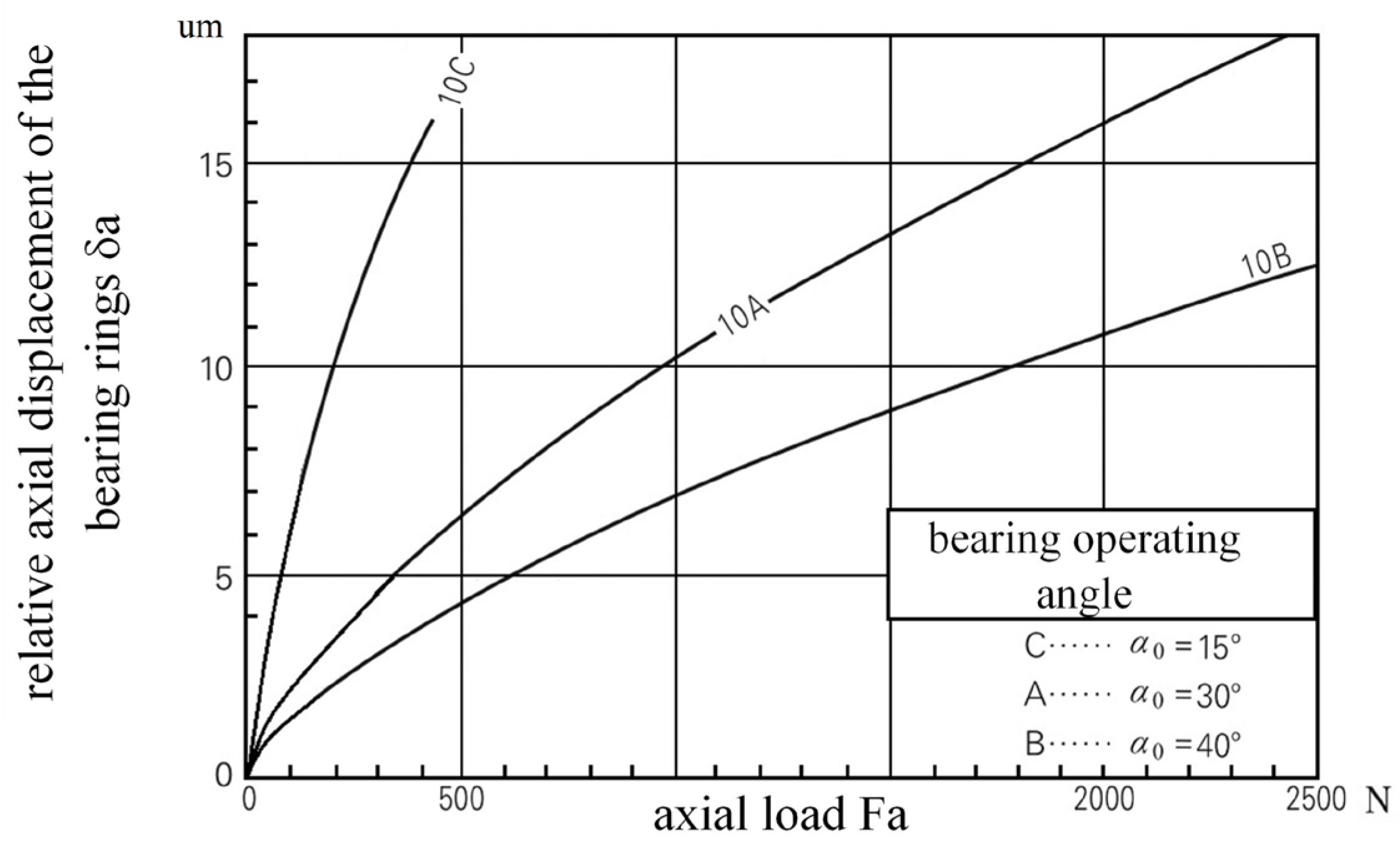
7] from the point of view of the stability of the machining process and is directly related to the stiffness of the spindle and the type of machining being carried out at a given moment. In addition to the general advantages of rolling bearings (quiet running, compact design, high failure-free operation, maintenance-free operation), the choice of angular contact bearings for machine tool spindles is based on their ability to transfer loads both axially and radially. Stiffness in the selected direction is directly related to the so-called bearing operating angle (15–40 degrees) and is defined as the relative displacement (in μm) of the bearing rings as a result of the external force. An example dependency graph is shown in
Figure 1.
Adjusting the spindle stiffness depending on the current operating conditions is a problem widely discussed in the modern scientific literature. Various authors have conducted various tests to change the stiffness of the machine tool’s spindle system [
9,
10,
11,
12,
13,
14] and have proposed various solutions, both active and passive [
15,
16], allowing for its change during spindle operation. The author presents a more extensive description of this issue in one of his earlier articles, which he wrote when he was dealing with the topic of active regulation of bearing preload [
17]. These types of structures are intended to maintain the stiffness of the spindle system at a sufficient, but as low as possible, level of bearing preload, so as to ensure minimal resistance to movement and negligible wear of the bearings while maintaining their stable operation.
In this article, the author presents his own design of a machine tool spindle equipped with an active bearing support, which allows the preload of the bearings to be changed during its operation. This change is made using piezoelectric elements in the full range of preload values for the B7206-CT-PS4-UM bearings from FAG [
18]. For this type of bearing, the preload value is in the range of 60–430 N and is selected automatically using a dedicated control algorithm. This type of solution can be called fully active. To build the active support, three PSt 150/10/40 VS15 piezoactuators from Piezomechanik GmbH, München Germany [
19] were used, placed parallel to the spindle axis and spaced at an angle of 120 degrees to each other. The piezoactuators were equipped with a strain gauge system that allowed for monitoring their load during operation and they were powered using a three channel SVR 150/3 power supply from Piezomechanik GmbH. Additionally, the active support had three built-in MDKa–F1 displacement sensors from VIS with an accuracy of 0.4 μm. The detailed construction of the complete test stand along with the description of preliminary tests and model tests was presented in articles [
20,
21].
Previous works have published preliminary tests for the station presented in the work with a model machine tool spindle equipped with an active bearing support. They only showed the structural correctness of the station and its correct operation under the influence of external forces. In none of these works did the author present a specific solution on how and on the basis of what parameters the control of the active support could be implemented. The aim of this article is to present the results of the process of selecting and optimizing the settings of the PID controller implemented in the LabView program that controls the preload of bearings in a model machine tool spindle. The process of checking its correct functioning was carried out for spindles with different spacings of bearing supports (154 mm—shaft A and 204 mm—shaft B). The value of the amplitude of forced vibrations of the front spindle tip, which was monitored continuously, was used as a control parameter for the correct operation of the control system. The most important novelty of this article is the developed control algorithm and the selection of its optimal operating parameters. After applying this algorithm, it is possible to actively reduce the vibration amplitude of the front spindle tip based on its actual measurement. The control algorithm adjusts the bearing preload values thanks to the use of piezoelectric actuators. When such a need arises (due to an excessive increase in the vibration amplitude), the control system changes the output value of the PID controller, which results in a change in the bearing preload value and at the same time limits the vibrations of the spindle tip. The development of a complete active control system is the greatest value and novelty in the presented work. In the literature known to the author, no similar solution has been presented, i.e., the use of a control system based on the LabView program, which would allow the control and simultaneous correction of the preload of the spindle system.
2. Natural Frequencies of the Spindle System
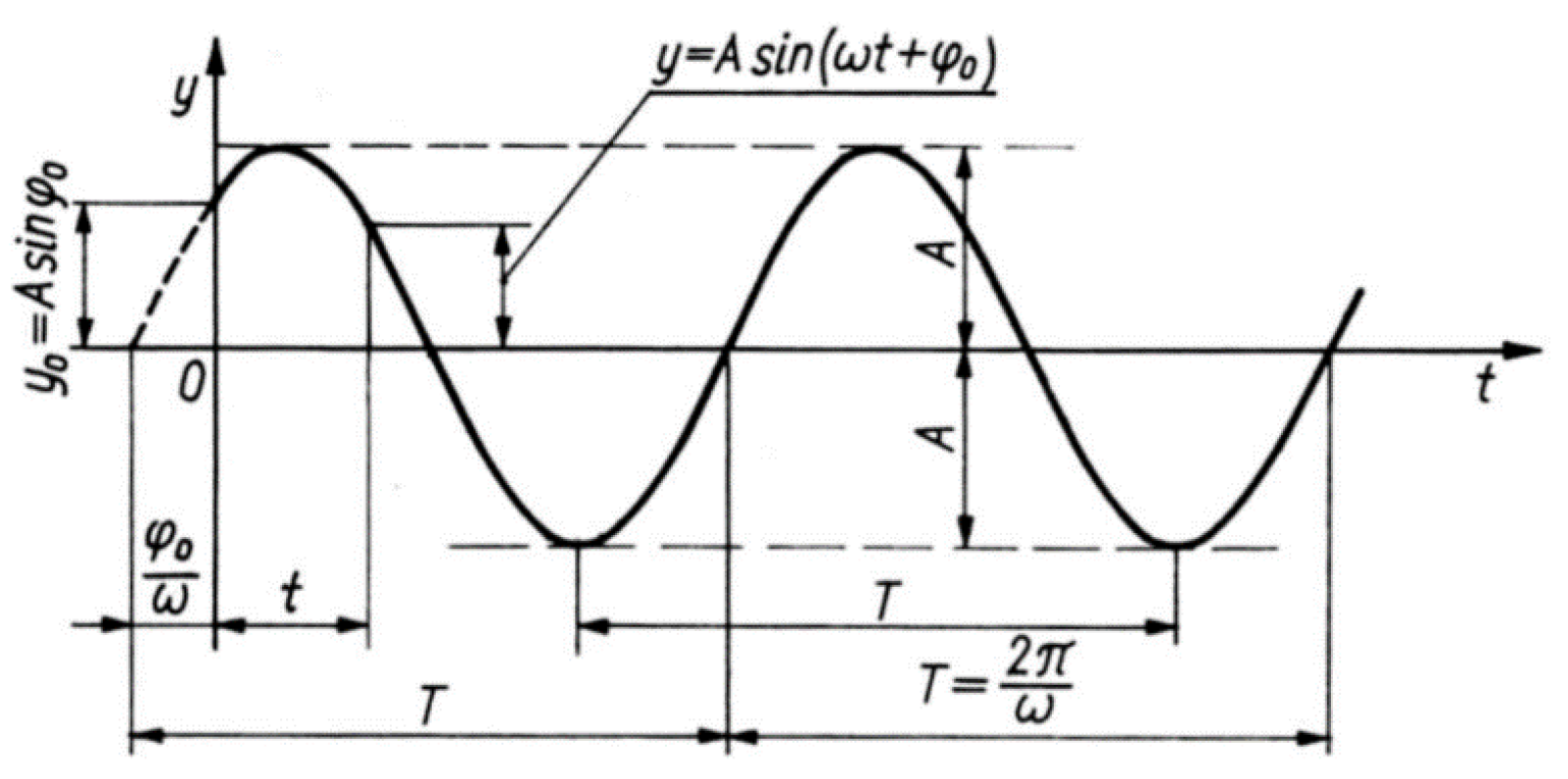
In mechanical structures, such as spindles or electro spindles of machine tools, the basic construction element is the shaft, which, from the point of view of mechanics, should be understood as a rod or beam element. In these types of element, their dynamics are a very important issue. For this reason, each time when designing a spindle, one should remember about vibrations, which, caused by even small forces in resonance conditions, may lead to permanent destruction or damage to the structure. The simplest example of a periodically variable load is the harmonic excitation, which is graphically presented in
Figure 2 and can be described by the following formula.
where:
Figure 2.
Harmonic forcing, where
A—vibration amplitude;
ω—circular frequency of vibrations,
φ0—phase shift angle;
t—time [
22].
Figure 2.
Harmonic forcing, where
A—vibration amplitude;
ω—circular frequency of vibrations,
φ0—phase shift angle;
t—time [
22].
Each spindle system has a specific stiffness, which results from many factors. In this work, the author focuses on the possibilities of changing the stiffness of the spindle system during its operation. The change in stiffness is also related to the change in the value of the system’s resonance frequencies. At this frequency, even a small periodic force can cause resonant vibrations of significant amplitude. Therefore, you should avoid working around these frequencies. In dynamic systems with many degrees of freedom, there are many natural frequencies of the system, and resonance may occur for each of them. Resonant vibrations with the largest amplitudes occur at the lowest frequencies, which often occur in the spindle working area.
The spindle assembly is a system composed of an elastic beam (spindle) and elastic supports (bearings). There are two types of natural vibration and forms of vibrations accompanying them. These are flexural vibrations of the spindle with small vibration amplitudes in the bearing supports, and spindle rocking, during which the spindle shaft behaves almost like a rigid body, and large amplitudes occur in the bearings. This second type of natural vibration is the main interest of this work, because its frequency and amplitude are determined by the elastic properties of the bearings. Actively changing the stiffness of the bearing supports is the action that can most influence the spindle rocking and the related natural frequencies and forms of vibrations. However, it has a small impact on the spindle’s flexural vibrations.
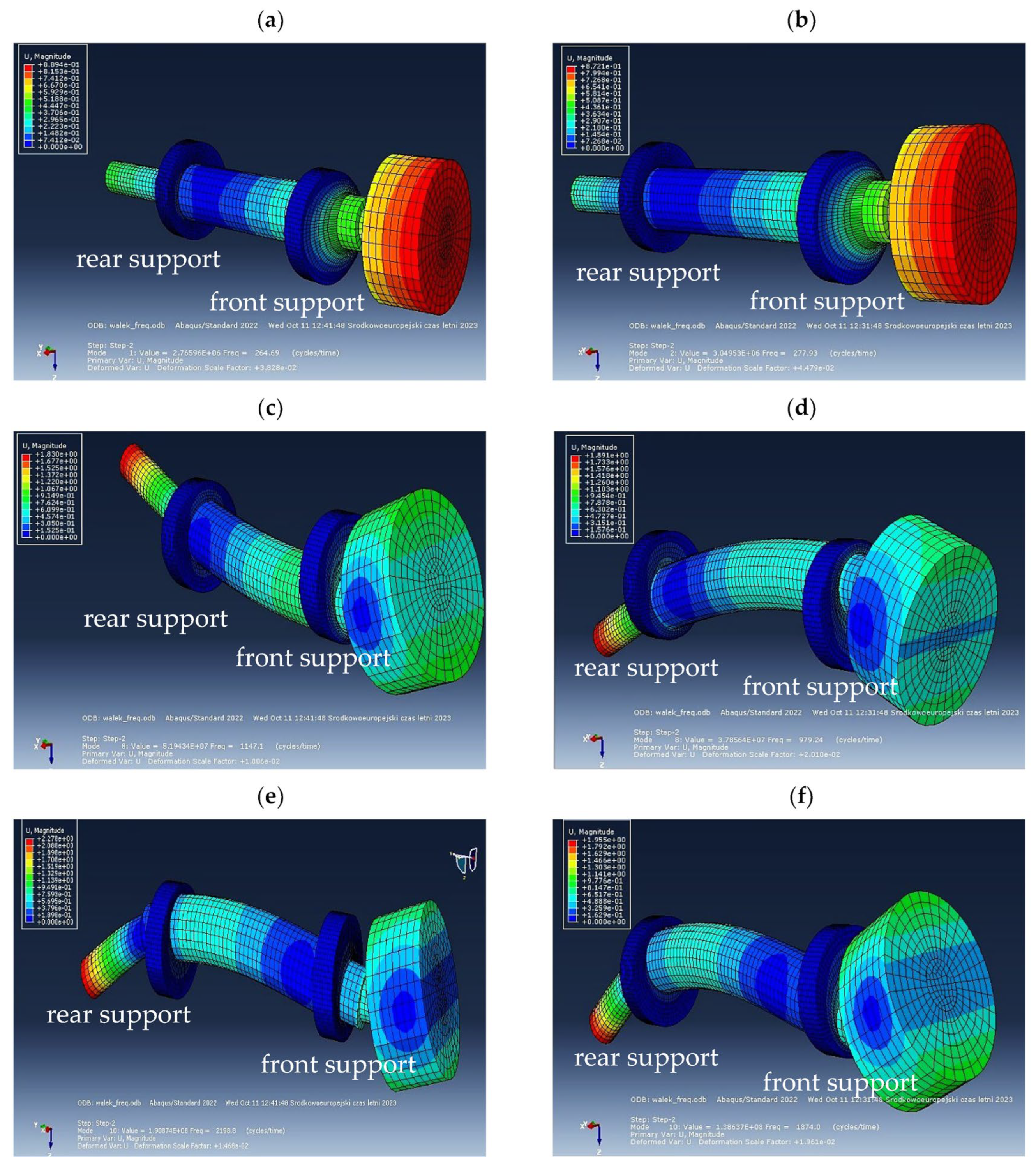
To initially determine the frequency and mode of the natural vibrations of the tested spindle, a Dassault System software called Abaqus 6.14 was used. Due to its computational capabilities, this program introduced a simplification consisting in modeling only the spindle shaft with two rings that imitated bearings. These rings were fixed on the outer surface, thus modeling the fixation in the spindle body. The research assumed that the modeled spindle would be an example of a grinding spindle. The model used C3D8R finite elements. The mesh size was set at 0.005 m. During the calculations, the bearings were tensioned with a force of 412 N, which corresponded to the catalog middle preload value. This preload was identical for both bearing supports. For this reason, a replacement ring was mounted on the front end of the spindle, the mass of which corresponded to the approximate mass of the grinding wheel for the grinding spindle. The stiffness of the bearing supports was changed by changing the properties of the material from which the replacement bearing rings were made. To correctly determine the stiffness, a number of model tests were carried out, the aim of which was to determine the value of Young’s modulus for replacement rings. The model developed in this way allowed us to initially estimate the level of the three lowest frequencies and forms of natural vibrations.
These frequencies were as follows: shaft A—265 Hz, 1147 Hz and 2191 Hz; and shaft B—278 Hz, 979 Hz and 1874 Hz, respectively. The visualization of the results is shown in
Figure 3 for shafts A (left column) and B (right column).
Based on the results, it was found that the lowest natural vibration frequencies were 265 Hz for shaft A and 278 Hz for shaft B, which corresponded to the form of vibrations associated with the spindle rocking, which is accompanied by the largest relative displacements of the bearing rings. This theory was confirmed by the research whose results the author included in the article [
3].
The natural frequencies determined in this way were used to estimate the range of harmonic excitations on a real object. The range of 150–450 Hz was adopted for experimental research. As part of the preliminary research presented in article [
23], the author checked the correct functioning of the piezoelectric actuators (PSt 150/10/40 VS15 from Piezomechanik GmbH) mounted in the active support, the displacement sensors, and also showed that as the preload of the bearings increases, the stiffness of the system increases at the spindle and the amplitude of vibrations of its front tip decreases. These tests consisted of a manual (step) change of the bearing preload value in their full range (60–430 N) and the measurement of the average frequency value for the first form of the spindle’s natural vibrations. In this way, it was demonstrated that the system is sensitive to changes in the bearing preload value. These results gave the impetus for further work on the fully active control of the preload value and active change of spindle stiffness during its operation.
4. Active Adjustment of Bearing Preload
At a further stage of the research, the author assumed that the change in the bearing preload would depend on the amplitude value for the front end of the spindle. A non-contact sensor was used to measure this displacement (design IPPT PAN Warsaw [
25]). This sensor was placed in such a way as to directly measure the vibration amplitude of the spindle tip, not the substitute mass. This mass was mounted on the shaft using an additional bearing type 61903 from FAG to ensure the ability of the spindle to operate and the possibility of connecting the exciter. The bearing used may partially dampen the vibrations of the shaft itself, which would result in measurement inaccuracies, and the results themselves would not reflect the behavior of the spindle tip. Based on model tests, which in the case of the first mode of natural vibrations presented the behavior of the shaft as a rigid body, it should be noted that the shaft vibrations at the place of sensor application will be smaller than those observed at its tip. A view of the spindle (1) with the mounted displacement sensor (2), the substitute mass (3) and the exciter connected to the substitute mass (4) is shown in
Figure 5.
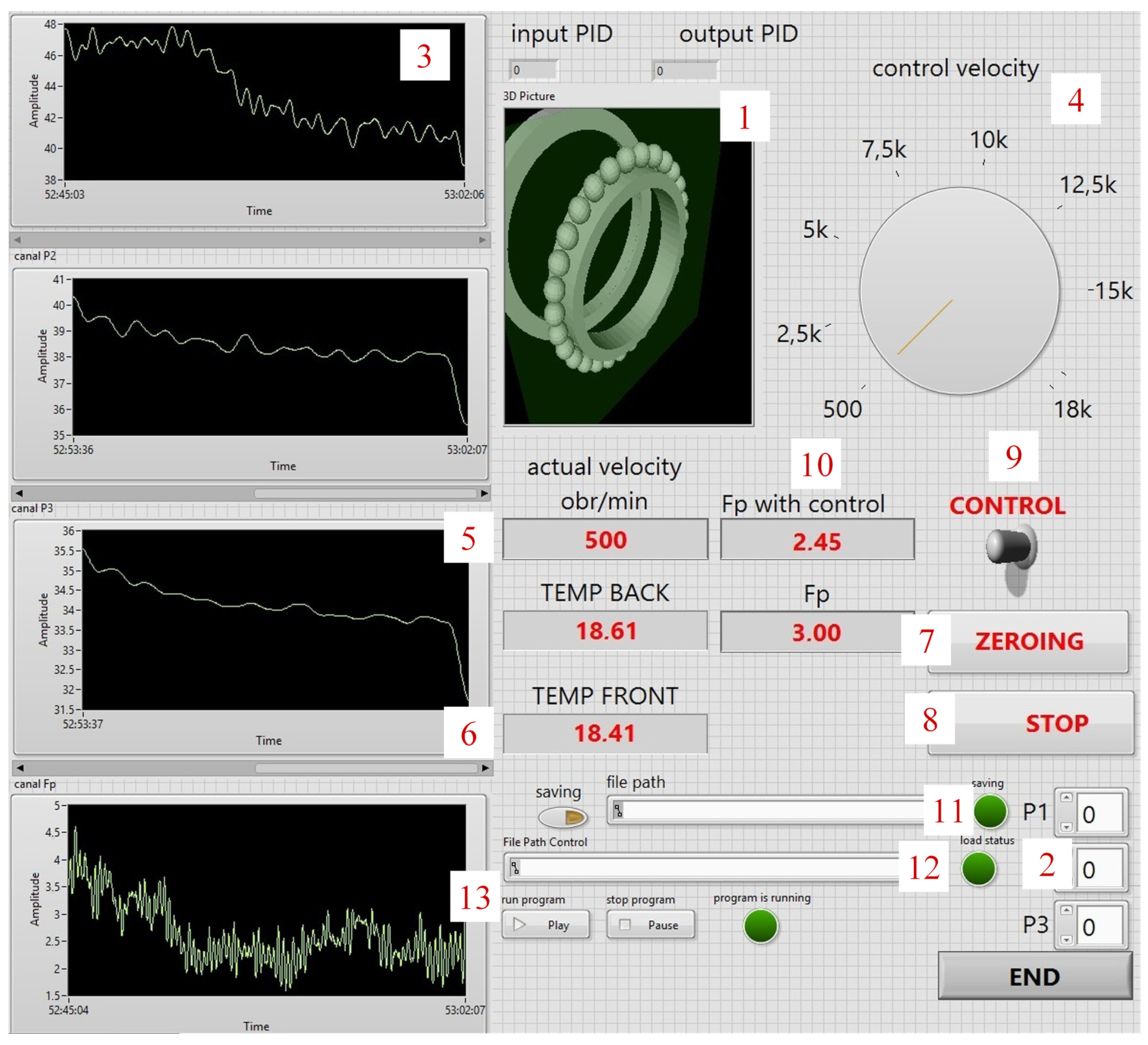
The active adjustment of the preload was performed using an application developed in LabVIEW. It had the ability to visualize the operation of the bearing in the active support (1), manually set the advance of the piezoactuators (2), display the relative values of the displacement of the bearing race (3), set the spindle speed (4) and read it (5), measure the temperature for the front and rear bearing support (6), zero the measurement values (7) and end the measurement (8). The application uses functions that were not available in its earlier version, which was used for preliminary research [
20]. These functions include switching on the control (9), monitoring the parametric value of the spindle tip displacement on the basis of which the active support preload values (10) were selected, the ability to save measurement data (11), load the spindle work program (12) and an additional amplitude chart displacements for the front end of the spindle (13). The front view of the LabView application panel is shown in
Figure 6.
The control algorithm was based on a typical PID controller, and its settings were selected based on an experiment. This experiment consisted of repeatedly starting the spindle at a speed of 500 rpm and with forcing generated by a GW-V20 type exciter from Data Physics. The forcing was performed using a sweeping signal in the frequency range 150–450 Hz. The test time was set at two minutes. First, the P parameter was selected with the remaining controller elements turned off (I = 0, D = 0). An initial value of p = 1 was adopted, which was then increased by 0.1 until there was no improvement in the control quality, calculated as a percentage of the decrease in the spindle tip displacement amplitude. An identical principle was adopted when selecting the I parameter, with the difference that in this case the value increased from 0 to 0.01. Due to the lack of significant improvement in control quality after adding the D parameter, it was decided to abandon it.
The research assumed that the optimized value of the control parameters will be the best overall when over the entire excitation area, the largest percentage decrease in the spindle tip displacement amplitude is achieved. With this assumption, the focus was on ensuring that overshoot did not occur, i.e., the amplitude value was not higher, even for a moment, than at the moment preceding the control. Efforts were made to reduce the control error by following the principle of manual tuning, which can use commonly known regularities (
Table 1).
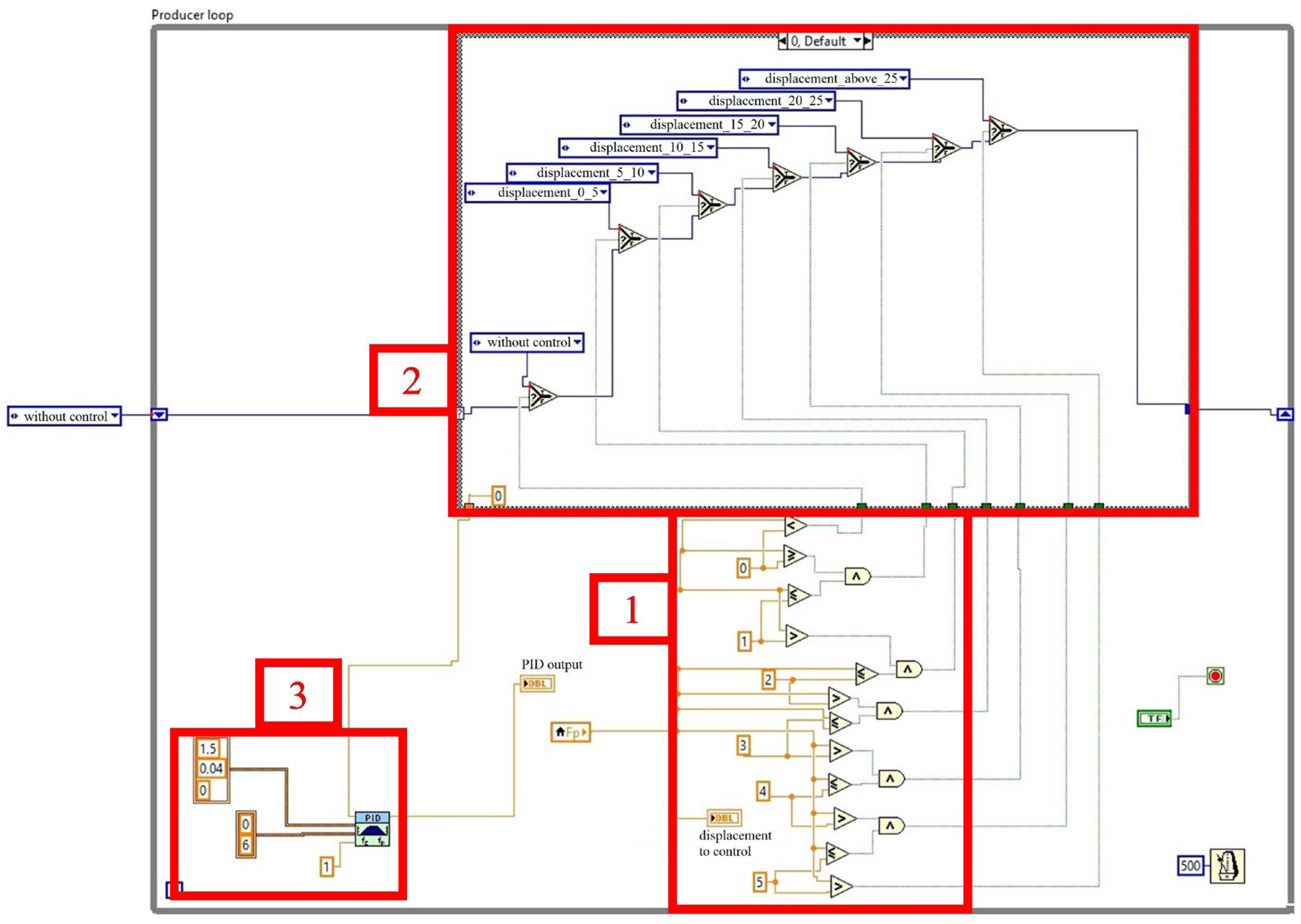
Ultimately, the following operating parameters were adopted for the PID controller. The value of individual elements: p = 1.5, I = 0.04 D = 0, Output parameters 0–6, dt(s) = 1, time loop 500 ms. The control application used a while loop, in which three areas were distinguished (loading the displacement amplitude value, classification into the appropriate group and determining the control value for the active support).
Figure 7 shows the block diagram for the control application. It was modeled on the basis of a while loop, in which three areas were distinguished. The first one was area (1), where the spindle tip displacement value was loaded and then, based on conditional instructions, it was classified into one of six ranges (2). The ranges were selected to take advantage of the full range of piezoactuator displacement. After the appropriate classification of the spindle tip displacement value, the control value was determined and loaded into the PI controller (3), which was responsible for controlling the active bearing support.
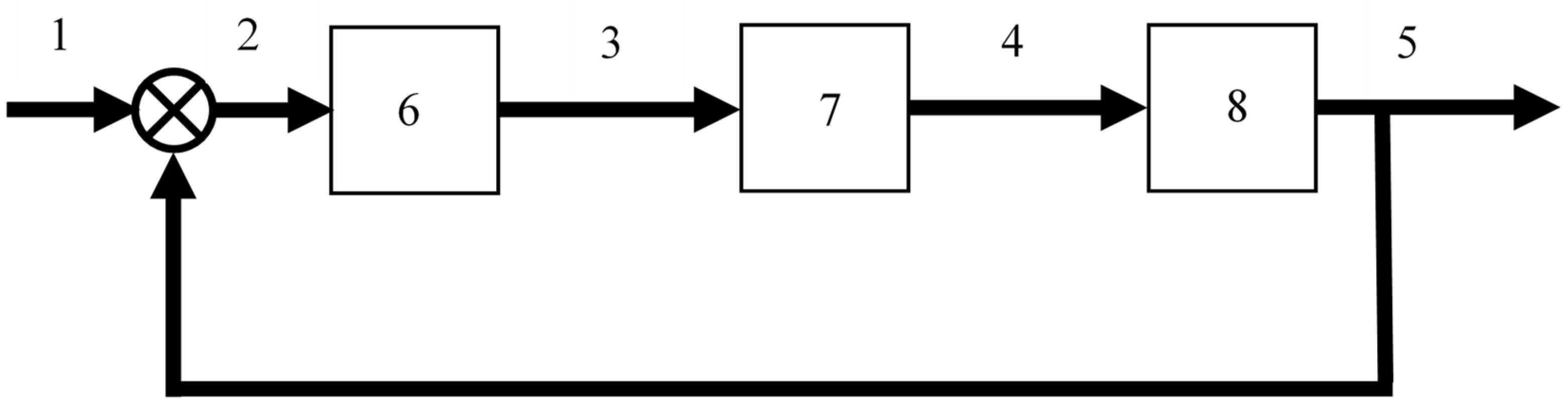
Figure 7 shows a block diagram for the active support control system. It was modeled using a while loop with a clock time of 500 ms. It had three areas: 1—loading the displacement value of the front spindle tip (signal from a non-contact displacement sensor); 2—classification of the displacement amplitude value into one of six ranges, <0–5), <5–10), <10–15), <15–20), <20–25) and above 25 um, 3—classifying the displacement value, the control value was read and entered into the PID controller. This controller then gave the output value controlling the advancement of the piezo actuators. The piezoactuators, pressing on the outer bearing ring, increased the preload value of the bearing system and at the same time reduced the amplitude of the displacement of the front spindle tip. The principle of operation of the entire control system can be observed by analyzing the control algorithm in
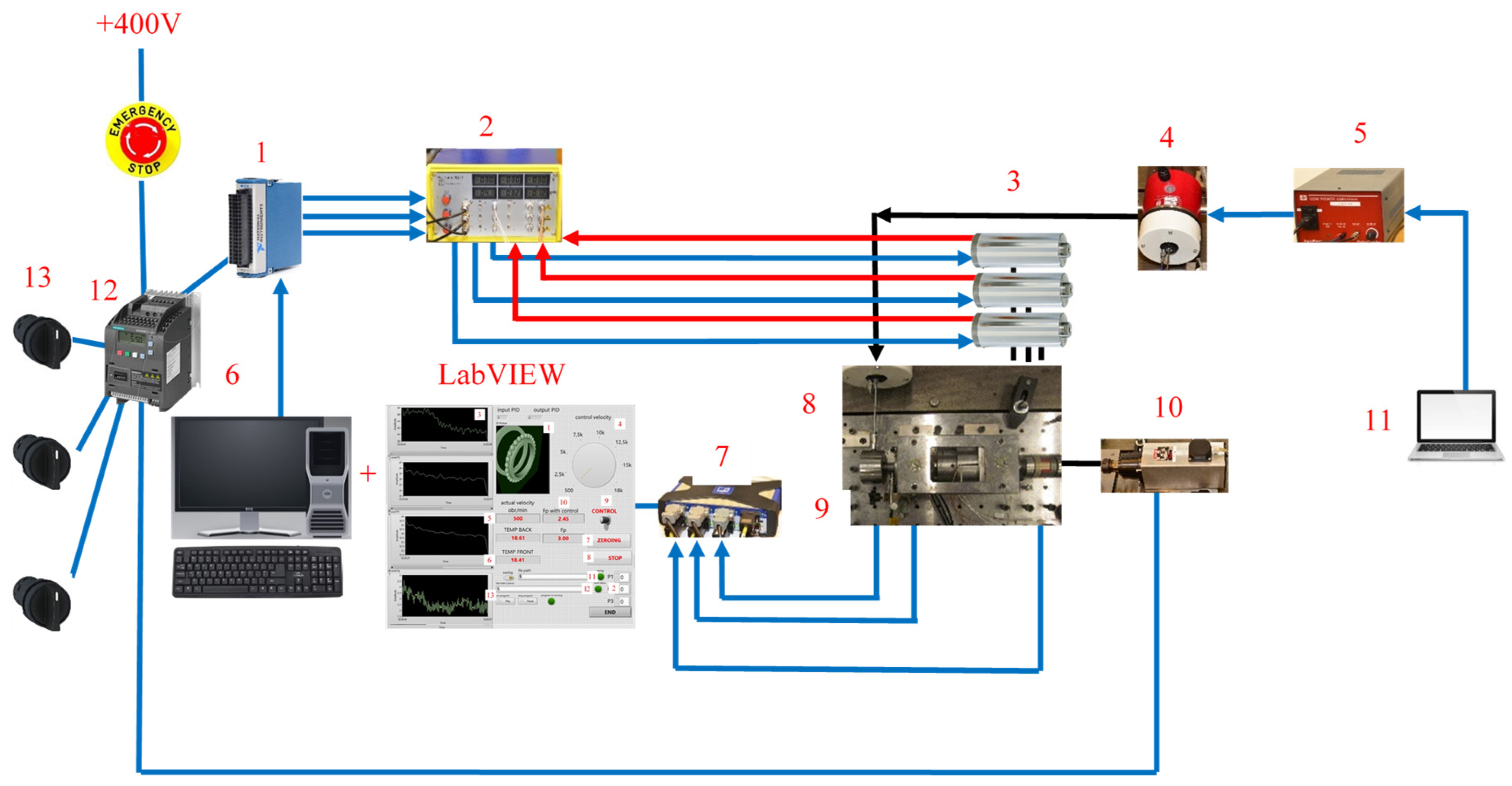
Figure 8 and the measurement circuit diagram in
Figure 9.
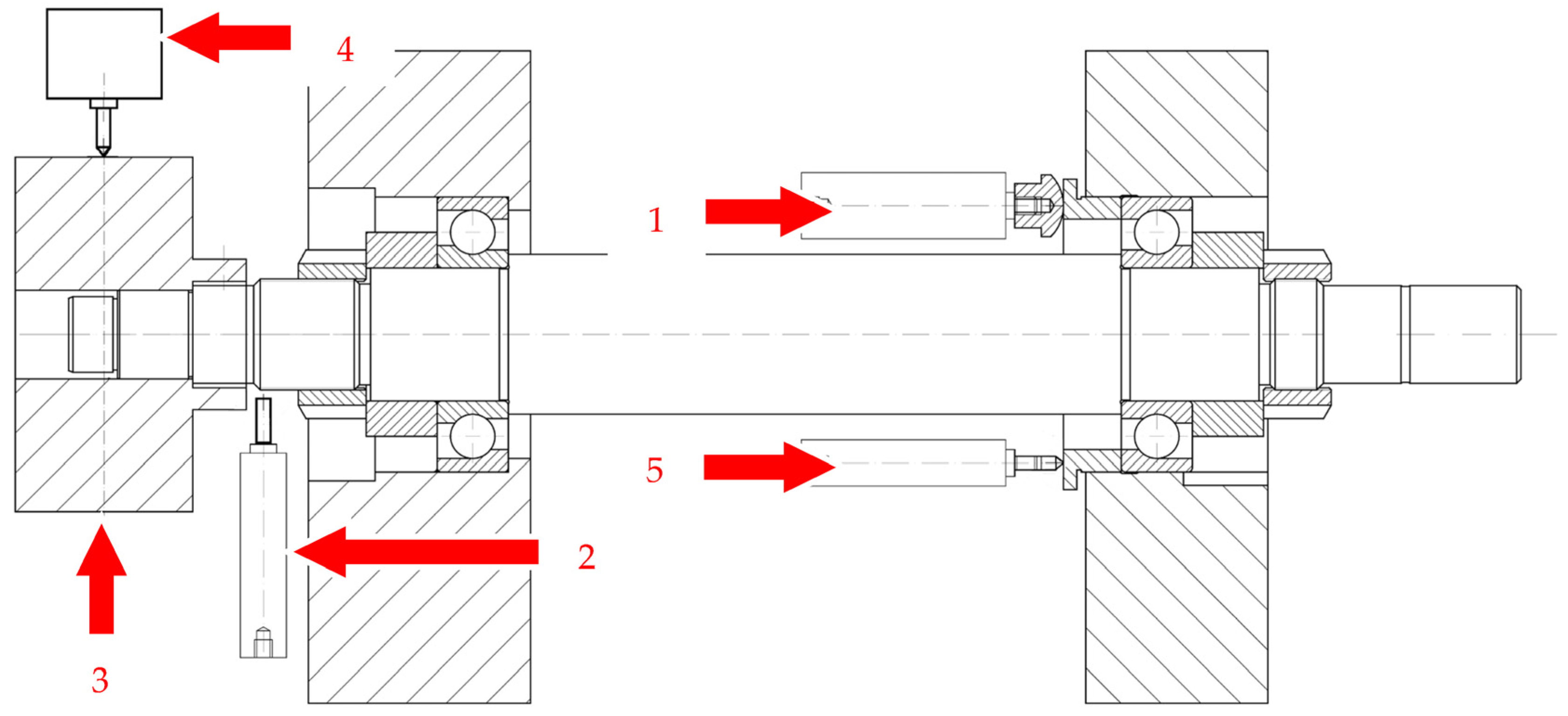
To make it easier to understand the operation of the active support and determine the measuring and actuating elements,
Figure 10 shows a diagram of the spindle system with the active support. Shown is the piezoelectric element (1), the displacement sensor of the front spindle tip (2), the equivalent mass (3), the exciter (4) and the displacement sensor of the outer bearing race (5).
After selecting the appropriate controller settings, measurements were carried out for two rotational speeds: 500 and 1000 rpm. The range of rotational speeds was limited due to the way the replacement mass was placed on the spindle tip and the external forcing of the system. Between the replacement mass and the spindle, a bearing type 61903 from FAG was installed, which was mounted on the shaft through a press-fit connection. Another limitation was the time loop of the control algorithm. Due to the lack of a signal processor [
26], the sampling frequency of the measurement signal and the determination of control values based on the while loop were significantly limited. The sampling frequency of the measurement signal was 900 Hz and the time of one measurement cycle was 120 s. Five repetitions were performed for each rotational speed. Then, the measurements were pre-averaged, obtaining data packages of 1080 samples. Research tests defined in this way were carried out for both shaft lengths (shafts A and B).
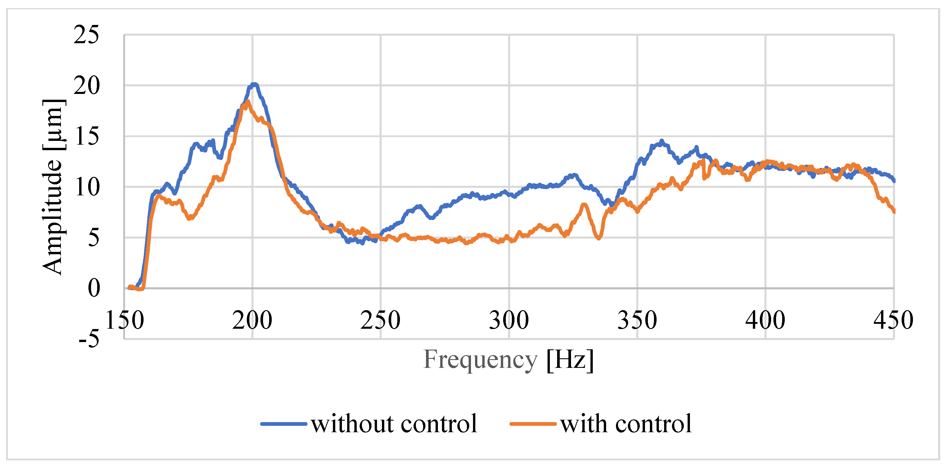
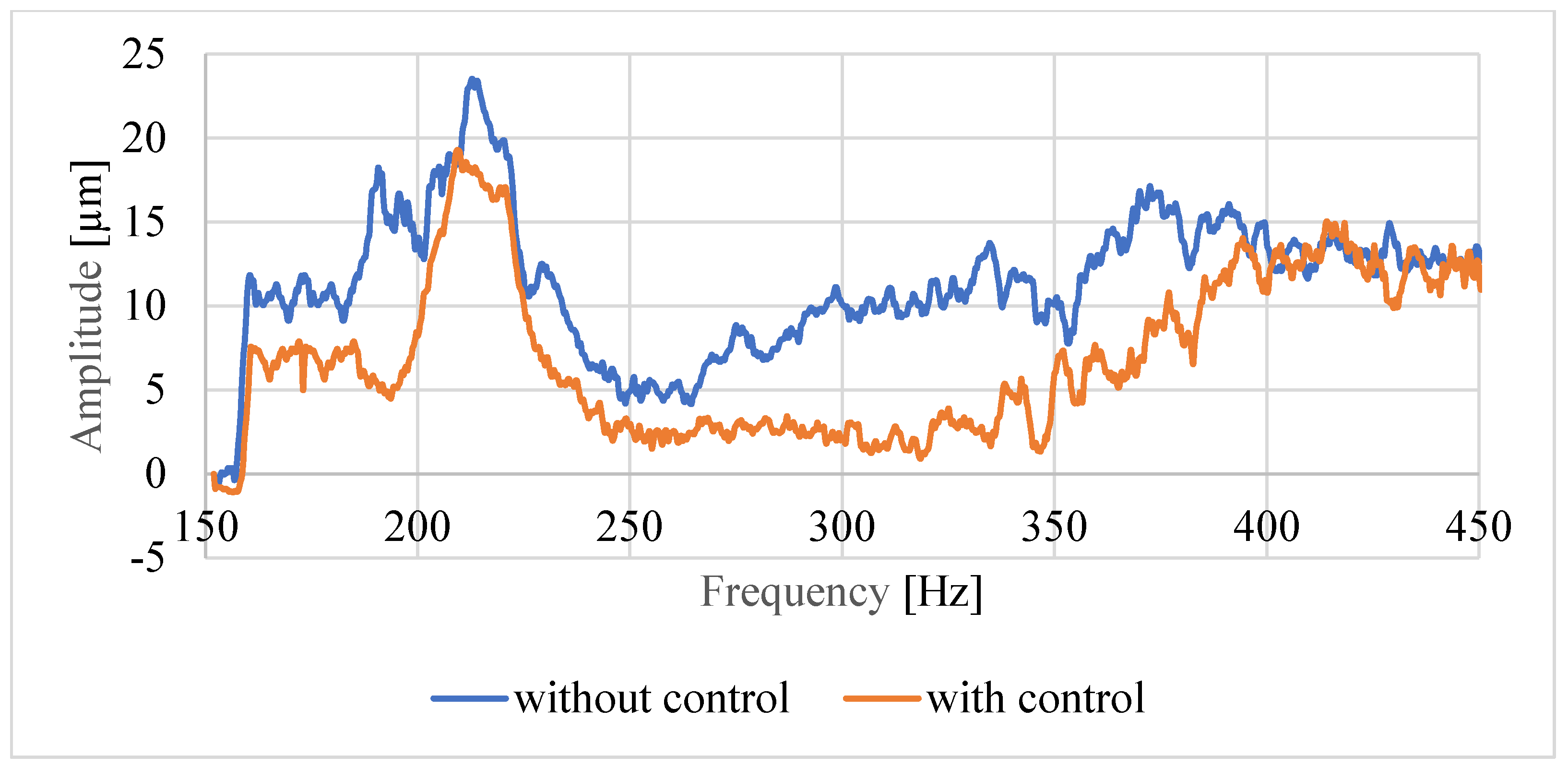
Further analyses were carried out on the basis of the data prepared in this way. Examples of spindle tip displacement charts recorded using a non-contact sensor for both shaft lengths and the same rotational speed of 500 rpm are shown in
Figure 11 for shaft A and
Figure 12 for shaft B. We observed the average value from five trials for two time courses, without and with active control. We observed that the active system worked properly and reduced the amplitude of the spindle tip displacement. The graphs for the higher rotational speed of 1000 rpm were of a similar nature; therefore, they were not included in this article. However, they were used to conduct statistical analysis to confirm the correct operation of the control system.
Figure 11 and
Figure 12 show two graphs of the spindle tip displacement amplitude. The measured value without the active control system is marked in red, and the measured value is marked in blue after the control is applied. We see that for each excitation value in the frequency range 150–450 Hz, there was a decrease in the value of the spindle tip displacement amplitude.
5. Statistical Analysis
The graphs presented in
Figure 11 and
Figure 12 may not provide a clear answer as to whether the proposed control system works properly and whether reducing the vibration amplitude of the spindle tip is significant. To check this relationship, the Statistica program was used to perform the calculations. The measured average values of the maximum displacement amplitudes for both rotational speeds (500 and 1000 rpm) and both bearing support spacings (154 and 204 mm) of the shaft were used as the input parameters.
The statistical analysis was carried out based on a method called single-variant significance of differences, the so-called ANOVA (Analysis of Variance) method [
27,
28]. It allows you to check whether the analyzed factors (active adjustment of bearing preload) influence specific results (amplitude of the vibration displacement of the front spindle tip). Based on the calculations, a probability level of 0.05 was determined for the Student’s
t-test value and the null hypothesis was rejected. Thanks to this, it was possible to start estimating the level of significance of differences. For this purpose, the measurements carried out after developing an active bearing support control algorithm were divided into eight groups, four for each bearing support spacing. Groups 1, 3, 11 and 33 concerned the speed of 500 rpm (measurements without and with control), and groups 2, 4, 22 and 44 concerned the speed of 1000 rpm (measurements without and with control). In both cases, the significance level of differences was set at
p < 0.05 and testing was carried out using two types of post hoc test (NIR test and Tukey’s test) [
29]. Examples of statistical analysis results obtained on the basis of these tests are presented in
Table 2 and
Table 3, and they concern a shaft with a support spacing of 154 mm. Due to the type of study, only the
p values obtained for the comparison of groups 1, 3, 2 and 4 (marked in yellow in the table) were significant.
The statistical analysis was carried out because based on graphs 11 and 12 it was not possible to clearly determine whether the control algorithm for the active support performed a specific task. The results from
Table 1 and
Table 2 confirm that for both shafts A and B there was a statistically significant reduction in the vibration amplitude after using the active support control system. These results also confirm that under the operating conditions of the model machine tool spindle, it is possible to actively change its vibration frequency and amplitude.
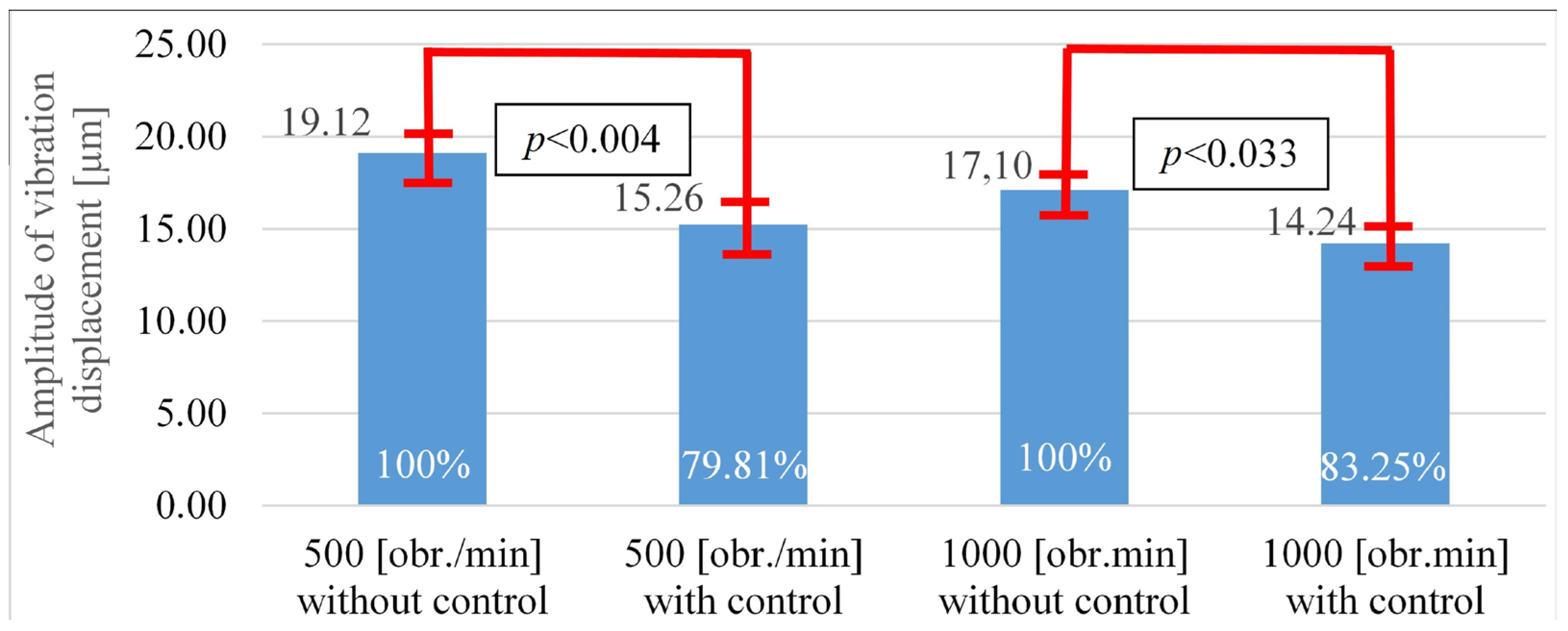
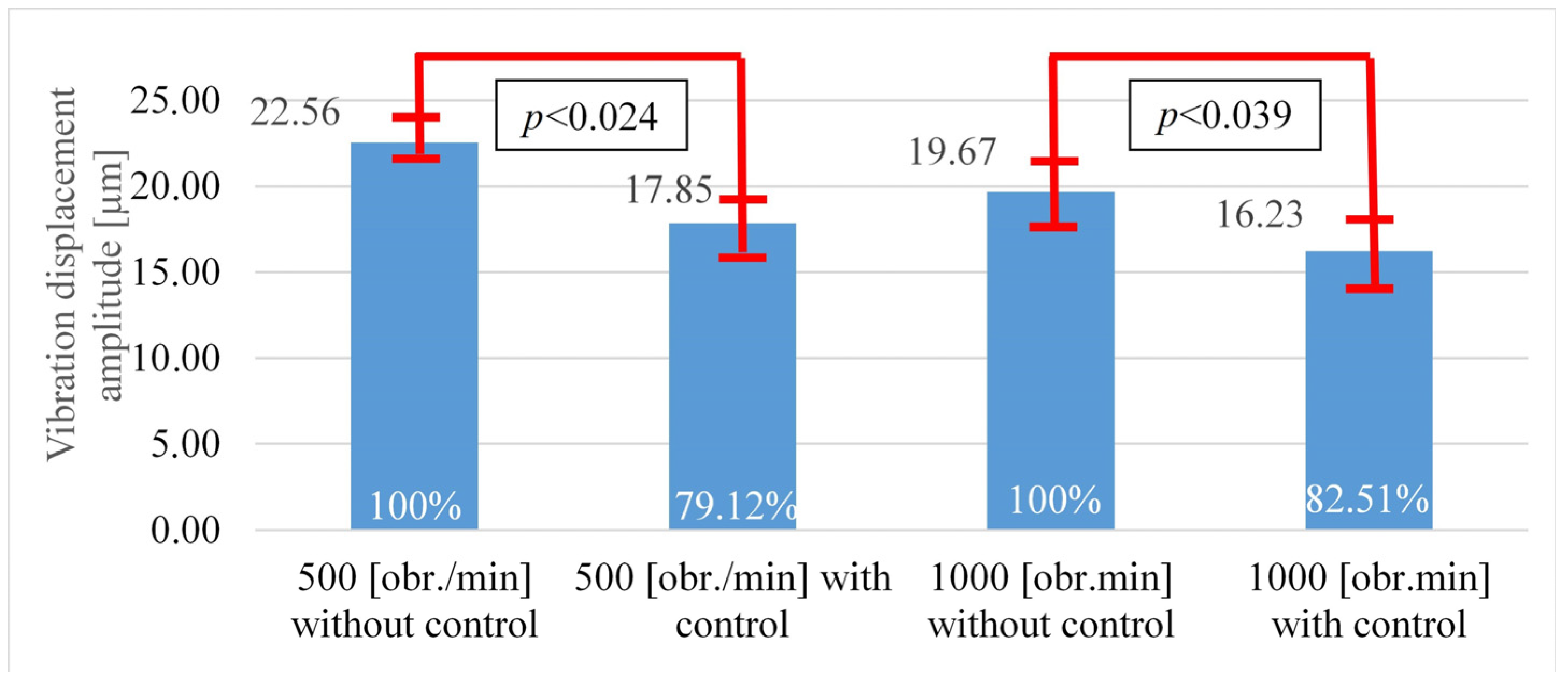
In both comparisons of the relevant groups of data, the significance level was below the assumed significance value (
p < 0.05); therefore, it can be concluded that the obtained decreases in the amplitude of spindle tip displacements were statistically significant. A graphical interpretation of these results is presented in
Figure 13 (version A) and
Figure 14 (version B). The change in the value of the
p coefficient with an increase in rotational speed suggests that the obtained result, i.e., a reduction in the value of the vibration amplitude of the spindle system for a speed of 1000 rpm, was less statistically significant. However, with certain assumptions
p < 0.05, we assume a 5% risk that the effects obtained may not actually occur. This condition is met for both variants of spindle speeds.


