Abstract
The explosive growth of massive data makes shingled magnetic recording (SMR) disks a promising candidate for balancing capacity and cost. SMR disks are typically configured with a persistent buffer to reduce the read–modify–write (RMW) overhead introduced by non-sequential writes. Traditional SMR zones-based persistent buffers are subject to sequential-write constraints, and frequent cleanups cause disk performance degradation. Conventional magnetic recording (CMR) zones with in-place update capabilities enable less frequent cleanups and are gradually being used to construct persistent buffers in certain SMR disks. However, existing CMR zones-based persistent buffer designs fail to accurately capture hot blocks with long update periods and are limited by an inflexible data layout, resulting in inefficient cleanups. To address the above issues, we propose a strategy called Amphisbaena. First, a two-phase data block classification method is proposed to capture frequently updated blocks. Then, a locality-aware buffer space management scheme is developed to dynamically manage blocks with different update frequencies. Finally, a latency-sensitive garbage collection policy based on the above is designed to mitigate the impact of cleanup on user requests. Experimental results show that Amphisbaena reduces latency by an average of 29.9% and the number of RMWs by an average of 37% compared to current state-of-the-art strategies.
1. Introduction
The advent of shingled magnetic recording (SMR) disks significantly improves the situation where conventional magnetic recording (CMR) disks are unable to meet the growing storage capacity demands of modern big data applications [1,2,3]. SMR technology successfully broke the area density barrier by widening the write heads and overlapping the tracks like shingles. However, the consequence of this is that non-sequential writes can destroy valid data on adjacent tracks. To prevent data corruption, the valid data of the adjacent tracks must be read into memory and merged with the new data before being written back to the native zone, the time-consuming operation that degrades system performance, known as the read-modify–write (RMW) [4,5].
To reduce the frequency of RMW operations, approximately 1% to 10% of the over-provisioned space within the SMR is configured as an internal persistent buffer to absorb non-sequential writes [6,7]. Incoming data is appended in the persistent buffer in a circular log manner, and the original logical block address (LBA) is recorded by a dynamic mapping table. To ensure that there is enough space in the persistent buffer to accommodate incoming new data, the buffered data is periodically migrated to the native zone. However, cleanup activities inevitably block user requests, especially under write-intensive workloads, and the inefficient persistent buffer management mechanism invokes cleanup activities frequently, thus degrading disk performance [6,7,8].
Currently, from the storage medium perspective, the internal persistent buffer can be divided into two categories: flash-based persistent buffers and magnetic recording-based persistent buffers. Given the excellent read/write performance of flash, Ma et al. [9,10] proposed embedding it inside SMR disks as an internal persistence buffer to reduce the duration of the cleanup activities. However, flash as the first-level buffer of SMR needs to take a large amount of write traffic, and its limited programs and erases (called P/E cycles) not only affect the efficiency of cleanup activities but also increase the cost of SMR disks. In contrast, the magnetic recording-based persistent buffer is widely configured in shipping SMR disks due to its low cost, high capacity, and durability. In general, magnetic recording-based persistent buffers can be constructed by SMR zones or CMR zones. In the case of the SMR-based persistent buffer, it follows the SMR philosophy of maximizing space utilization. However, SMR-based persistent buffers are subject to sequential write constraints, resulting in inflexible space allocation and frequent garbage collection (GC). As a result, many existing studies have attempted to reduce cleanup costs by improving the efficiency of space management in the persistent buffer [11,12,13]. Another case is a CMR-based persistent buffer without sequential write constraints, which means that its in-place update feature can reduce the cleanup frequency to some extent and is also the type of interest in this paper. Several existing works have proposed approaches to optimize the management of CMR-based persistent buffers. For example, dm-zoned [14] divides the CMR buffer into segments of the same size as the SMR zone to buffer update data. Hajkazemi et al. [15] further determine the optimal size of the segments based on the data layout scheme of dm-zoned. Differently, the latter proposes a spatial locality-based promotion operation to reduce the cleanup overhead. Recently, Wu et al. [16] proposed a loopback-based persistent buffer management strategy to avoid the write-back of hot (frequently updated) blocks. However, these studies did not achieve the expected performance gains, mainly due to the following reasons. Firstly, the lack of sufficient knowledge about the locality characteristics of the workload prevents frequently updated blocks from being accurately captured. These blocks move back and forth between the persistent buffer and the SMR zones, increasing the frequency of buffer cleanup. Second, a single data layout scheme cannot efficiently manage blocks with different update frequencies, reducing the efficiency of buffer cleanup. Finally, in a zone-level write-back mechanism, the size and spatial locality of the evicted victims are important factors affecting the buffer cleanup cost, and these factors have not been considered in these studies, leading to unpredictable write-back durations.
To improve the efficiency of CMR-based persistent buffer cleanup, we propose a novel management strategy called Amphisbaena, which is optimized in three phases: (1) exploiting the knowledge provided by write requests in the workload to capture frequently updated blocks; (2) managing blocks with different update frequencies in a way that dynamically partitions the persistent buffer; (3) using a low-overhead GC policy to minimize the impact of buffer cleanup on user request latency. Specifically, the main contributions of this paper are as follows.
- A two-phase data block classification method is proposed to capture blocks with frequent updates, thus reducing the frequency of write-back of hot blocks. In the first phase, the data classifier predicts the update frequency of blocks based on the explicit characteristics of the current write request. In the second phase, the data classifier further mines the implicit characteristics of blocks and assigns specific roles to them to reserve frequently updated blocks in the buffer for as long as possible.
- A locality-aware buffer space management scheme is developed to improve the efficiency of buffer cleanup. To isolate blocks with different update frequencies, the persistent buffer is partitioned into a high-frequency buffer (HFB) and a low-frequency buffer (LFB). The HFB uses the fine-grained unit to hold frequently updated blocks for better space utilization, while the LFB uses the coarse-grained unit to improve write efficiency for cold (infrequently updated) blocks. In addition, each buffer can be periodically reallocated to match the access pattern of the workload.
- A latency-sensitive garbage collection policy is designed to minimize the overhead of the zone-level write-back mechanism. First, the time-consuming victim collection process is broken down into sub-stages and collection is stopped as soon as a new write request is detected at a checkpoint, reducing the blocking time of user requests. Then, a metric called fragmentation level is used to guide victim selection to minimize unnecessary RMW operations during data migration.
We evaluated Amphisbaena with real-world workloads from Microsoft Research (MSR) Cambridge [17], and verified its I/O performance improvement on a real HM-SMR disk. The experimental results show that Amphisbaena can reduce the average latency by 29.9% and the number of RMWs by 37% on average compared to the latest strategies.
The rest of the paper is organized as follows. Section 2 describes the background and motivation. Section 3 presents the related work. The overall architecture of Amphisbaena is provided in Section 4. Section 5 introduces the detailed design of the Amphisbaena. Section 6 shows the experimental setup and the analysis of the results. We conclude this paper and discuss future work in Section 7.
2. Background and Motivation
In this section, we present the background of SMR disks and persistent buffers in Section 2.1 and Section 2.2, respectively, and the motivation for our work is described in Section 2.3.
2.1. Characteristics of SMR Disks
SMR is a promising technology for breaking through the bottleneck of perpendicular magnetic recording to further increase the area density of disks. Because SMR disks are an evolution of the existing CMR disk architecture, they can significantly reduce production costs and be easily integrated into modern storage systems [18,19]. The rationale behind the ability of SMR disks to increase in storage density is twofold. First, the tracks are overlapped like shingles to improve space utilization, and second, the write head is enlarged to 3~8 times the size of the read head (also known as R/W_Head), which allows the magnetic field generated by the write heads to concentrate the same amount of data in a smaller area [5]. Note that non-sequential writes must be handled carefully, as the enlarged write head can overwrite valid data on adjacent tracks. As shown in Figure 1, the width of W_Head is three times the width of R_Head. If the data on track A needs to be updated, the disk must read the valid blocks within the write head coverage (i.e., from track B and track C) into memory, merge them with the updated blocks, and then write them back to the native zone. This time-consuming update process is known as RMW. To avoid the domino effect caused by data updates, the entire disk space is divided into many bands/zones, each consisting of a group of tracks, and guard regions are placed between them. In this way, the data involved in the RMW operation is confined to one band/zone.
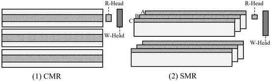
Figure 1.
Track layout difference between CMR and SMR disk.
Currently, SMR disks are classified into three types, drive-managed SMR (DM-SMR), host-managed SMR (HM-SMR), and host-aware SMR (HA-SMR) [7]. In particular, both DM-SMR and HA-SMR use a persistent buffer consisting of SMR zones (approximately 1% to 10%) to reduce the frequency of RMW operations. DM-SMR uses an internal Shingle Translation Layer (STL) [2,3] to hide data management details, allowing it to operate like a CMR disk. Unlike DM-SMR, HM-SMR and HA-SMR can provide real-time information to host applications about the location of the write pointer and the number of active zones, which can help the host make data placement decisions. However, the performance of DM/HA-SMR disks is degraded by frequent buffer cleanup activities. To achieve predictable performance, the persistent buffer is no longer configured on HM-SMR disks, and all non-sequential write requests return error messages to the host. Typically, HM-SMR disks reserve a fixed number of CMR zones that can be used to store metadata or build a custom persistent buffer [1,7,14,15,16] to meet the performance needs of the storage system in different scenarios. Recently, the industry has been developing a hybrid SMR to further achieve the balance between capacity and performance [16,20]. Intuitively, the principles of HM-SMR and hybrid SMR are very similar in that both consist of CMR and SMR zones, and the data management strategies can be implemented on the host system. The difference is that the latter can dynamically adjust the ratio of CMR and SMR zones at runtime. Therefore, this type of disk is orthogonal to our strategy, i.e., our strategy can be integrated into it.
2.2. Optimization for CMR-Based Persistent Buffers
The reasonable use of a persistent buffer to accommodate non-sequential write data can effectively mitigate the performance degradation of SMR disks caused by frequent RMW operations. Currently, the persistent buffer in SMR disks includes a flash-based persistent buffer and a magnetic media-based persistent buffer. Intuitively, the performance of flash-based buffers may be better than magnetic media-based persistent buffers, but the former comes at a higher price. In practice, as back-end storage devices, SMR disks have to cope with a lot of write traffic. Under write-intensive workloads, this can place a heavy burden on flash memory, which suffers from endurance issues. Therefore, flash memory with limited erase cycles is not suitable as an on-disk buffer.
Magnetic recording-based persistent buffers are considered a practical solution because of their low cost and no erase-cycle limit. In general, a magnetic record-based persistent buffer can be constructed using either the SMR zone or the CMR zone. SMR-based persistent buffers are configured in most current SMR disks due to their ability to fully utilize disk space. However, sequential write constraints prevent data from being updated in place, requiring frequent cleanup to reclaim available space. Buffer cleanup inevitably introduces time-consuming RMW operations, which dramatically degrade the performance of SMR disks [21,22]. Compared to SMR-based persistent buffers, CMR-based persistent buffers have in-place update capability, which can reduce the frequency of cleanup to some extent. The emergence of HM-SMR disks configured with CMR zones provides a great opportunity to design flexible and host-controllable data layout schemes and garbage collection strategies. There have been several efforts to optimize CMR-based persistent buffers. For example, Western Digital proposed an open-source solution for HM-SMR called dm-zoned [14]. The entire CMR space is divided into a fixed number of CMR zones of the same size as the SMR zones, and the CMR zones are organized in a set-associative manner. When the CMR zones are exhausted, a Zone-LRU [22] policy is used to evict the victim CMR zone. However, under temporal locality-dominated write workloads, the coarse-grained space allocation unit frequently triggers cleanup, severely degrading disk performance. Cache [15] adopts a data layout scheme similar to dm-zoned, except that the former proposes a spatial locality-based promotion operation to try to eliminate the need for garbage collection. However, the strategy omits any discussion of garbage collection policies, making it applicable only to spatial locality-dominated workloads. Recently, Wu et al. [16] proposed a loop-back logging strategy that uses append-write to improve write efficiency. Typically, under this data layout, victims can only be cleaned in a first-in-first-out (FIFO) way. To avoid frequent updates of blocks moving back and forth between the buffer and the native zone, blocks that belong to the hot zone are re-queued to the log header when the buffer is cleaned. In summary, these strategies either do not take into account the actual workload characteristics or lack efficient garbage collection policies, making them ineffective overall.
2.3. Motivation
To take full advantage of CMR-based persistent buffers, the characteristics of the workload and the inherent properties of SMR disks must be considered. This motivates us to gain insight into the key factors that affect the efficiency of CMR-based persistent buffer cleanup.
Differences in hot block update periods. The recency- and frequency-based classification methods use temporal locality to identify frequently updated blocks in the workload, which often yields satisfactory results [23,24,25,26,27]. However, in real-world workloads, some blocks have short update periods (in this paper, the update period indicates how many other unique blocks exist between two update operations to a block, where the update period is greater than the persistent buffer is called the long update period, and the reverse is called the short update period) but low update frequencies, while some blocks have long update periods but high update frequencies [28]. In this case, it is difficult to capture such blocks using a frequency- or recency-based classification method. In contrast, the reuse distance-based classification methods can accurately capture the blocks that are frequently updated and have long update periods by predicting the update distance of the blocks. To observe the distribution of block update periods under different workloads, we utilize the concept of reuse distance to quantify the block update periods. Figure 2 show the update period distribution of updated blocks under real-world workloads from MSR, where the blue dashed line indicates the persistent buffer size bound for the current workload (details of the persistent buffer size configuration are given in Section 6.1). For Figure 2a, the blocks with short update periods are about 83.7%, of which only 6.76% are updated once. Therefore, the frequency- or recency-based classification method can effectively identify the frequently updated blocks. In contrast, the workload shown in Figure 2b has more than 85% blocks with long update periods, and 70% of them are updated more than twice. Since the long update period blocks are greater than the size of the persistent buffer, this causes the frequency- and recency-based classification method to incorrectly treat them as cold blocks to be discarded. Frequently updated blocks that move back and forth between the persistent buffer and the native zones introduce unnecessary RMW operations, which lead to jittery disk performance.

Figure 2.
The distribution of the update period for block under real MSR workloads. In (a,b), the x-axis represents the average update period of an updated block, the left y-axis represents the number of logical blocks accessed by the write request, and each dot represents a logical block.
Although the reuse distance-based classification methods have been widely deployed with good practical results [28,29,30,31], these well-designed strategies applied directly to CMR-based persistent buffers may not yield satisfactory performance gains. There are two reasons for this: first, these strategies are designed for the RAM-based cache, and without the seek overhead of collecting victim blocks; second, the main purpose of these strategies is to accelerate read requests, whereas for SMR disks with write performance bottlenecks, more attention should be paid to the blocks with frequent updates and long periods. Therefore, it is necessary to develop a data classification method dedicated to the write-reuse distance to avoid the write-back of blocks with frequent updates.
Conventional data layout scheme. Current persistent buffer data layout schemes fall into two broad categories: circular log-based or segment-based data layout schemes. To improve the write efficiency of SMR disks, the circular log data layout scheme appends the written data sequentially to the end of the log, but this also causes blocks in the same SMR zone to be scattered to different physical locations. When the buffer is cleaned, the victim block collection process triggers multiple time-consuming random read operations. Worse, victims can only be evicted in a FIFO fashion, regardless of update frequency, so some frequently updated blocks will migrate back and forth between the persistent buffer and the SMR zone. Compared to the former, the segment-based persistent buffer data layout scheme reduces the time-consuming collection of victim blocks to some extent by storing the blocks in fixed-size segments. However, to improve space utilization, a segment can often be shared by more than one SMR zone. Therefore, this scheme triggers a large number of RMW operations when evicting victims, resulting in unpredictable write-back overhead. In addition, most workload write requests do not always access the LBA space uniformly, and this inflexible mapping method results in wasted buffer space. To illustrate this phenomenon, we analyzed some real workloads of MSR. As shown in Figure 3a, the write requests cover the entire LBA address space almost evenly, while the write requests in Figure 3b are concentrated in a limited LBA address space. In the latter case, because the buffer space is not fully utilized, cleanup is triggered frequently, reducing disk I/O performance. Therefore, the data layout scheme of the CMR-based persistent buffer should be redesigned to improve the cleaning efficiency.
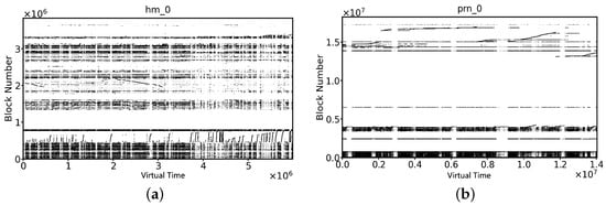
Figure 3.
The distribution of the write range for block under real MSR workloads. In (a,b), the x-axis represents the virtual time (i.e., the reference sequence of write requests), the y-axis represents the number of logical blocks accessed by the write request, and each dot represents a logical block.
Zone-level write-back mechanism. Buffer blocks must be periodically written back to accommodate the incoming blocks. In general, the persistent buffer adopts a zone-level write-back mechanism to evict buffer blocks within the same zone that reduces the write amplification generated by cleanup activities [6,7,19,32,33,34,35]. As shown in Figure 4, the RMW operation of the cleanup process consists of three steps: reading valid blocks from the native zone, collecting victim blocks, and writing back the merged blocks. Steps (1) and (3) require only one sequential read and write operation, while the collection of victim blocks in step (2) involves multiple read operations. In particular, the victim blocks are scattered within persistent buffer space, which can further exacerbate the time overhead of collecting them. In the worst case, it takes more than 30 s to write back a zone [6,7]. Under write-intensive workloads, frequently triggered cleanup activities can cause severe performance degradation on SMR disks. In addition, the spatial locality of the victim can also affect the native zone. In other words, the layout of blocks within the native zone determines to some extent whether future writebacks will trigger RMW operations. This is due to the fact that the victim blocks are scattered (i.e., have weak spatial locality), which corrupts the spatial locality of the native zone and can introduce unnecessary RMW operations in the next cleanup. In summary, the victim collection overhead of the zone-level write-back mechanism and the spatial locality characteristics of the victim are the main factors that affect the efficiency of the cleanup of the persistent buffer.
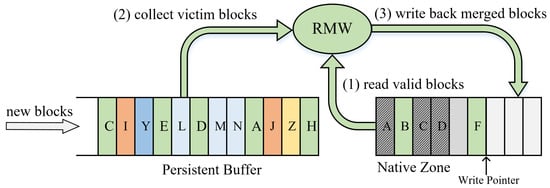
Figure 4.
Detailed descriptions of the RMW procedure during persistent buffer cleanup.
Our solutions. Combined with the analysis of existing studies in Section 2.2, in this section, we further clarify the key factors that affect the efficiency of CMR-based persistent buffers and use the following techniques to implement the proposed strategy: (1) to reduce the write-back frequency of hot blocks, we design a two-phase data block classification method to capture blocks with frequent updates but long periods; (2) to improve buffer cleanup efficiency, we propose a locality-aware buffer space management scheme to isolate blocks with different update frequencies; (3) to reduce the cost of zone-level write-back mechanism, we develop a latency-sensitive garbage collection policy to solve this problem. In addition, our ultimate goal is to utilize existing resources on the storage device to provide a cost-effective solution, rather than requiring over-reliance on other high-performance storage devices or redesigning the internal track layout of the disk. To this end, the study in this paper uses HM-SMR disks, which allow host-controlled data placement and management, to implement our proposed strategy.
3. Related Work
Optimizing the persistent buffer management strategies is one of the most important ways to improve SMR disk performance [7]. There have been many studies discussing how to reduce the cost of persistent buffer cleanup, focusing on two aspects: (1) persistent buffer data layout scheme; and (2) persistent buffer cleanup activity scheduling.
Persistent buffer data layout scheme. Most previous studies have focused on optimizing the SMR-based persistent buffer. For example, as a track-level data cleanup strategy, SACE [36] always prioritizes the eviction of RMW-free victims to reduce write amplification. Liang et al. [12] proposed a strategy called , which uses a combination of static and dynamic mapping to route data with different update frequencies to the appropriate buffer bands to reduce the cleanup burden. Ma et al. [11] observed that hot blocks that are written back frequently invite a large number of RMWs. To do this, they suggested dividing the persistent buffer into a hot block area and a cold block area and resizing both periodically. A persistent buffer management strategy called KFR [37] uses a redesigned disk layout and allocation unit to divide zone-scale space recovery into several smaller granular k-frames, which effectively reduces the performance recovery time of the disk. Moreover, Yang et al. [13] proposed a host-controllable virtual buffer management scheme that uses a portion of the SMR zones as a virtual buffer to share the write traffic of the persistent buffer.
Recently, the optimization of the data layout scheme for CMR-based persistent buffers has gradually gained attention. dm-zoned [14] is an open-source translation layer developed by Western Digital that uses device-provided CMR zones to build a persistent buffer, thereby enhancing the versatility of HM-SMR disks. Cache [15] further explores the optimal size of buffer allocation units based on the dm-zoned data layout scheme. Meanwhile, Wu et al. [16] proposed a loopback-based persistent buffer management strategy for hybrid SMR disks. This strategy avoids writing back hot blocks by re-queuing them instead of writing them back to the native zone. In addition, some studies have embedded NAND flash in SMR disks to act as a persistent buffer [9,10]. Although flash-based persistent buffers are more effective in improving the performance of SMR disks than magnetic media-based persistent buffers, they also introduce endurance and high-cost issues.
Persistent buffer cleanup activity scheduling. In addition to optimizing the data layout scheme of persistent buffers, several recent studies attempt to explore the optimal timing of persistent buffer cleanup to improve user quality of service (QoS). For example, Idler [38] heuristically induces buffer cleanup based on workload characteristics and persistent buffer occupancy, thereby reducing the frequency of block cleanup. More recently, a handful of works have attempted to use reinforcement learning models to intelligently schedule cleanup activities to reduce long-tail latency [39,40].
4. Amphisbaena Overview
Our proposed strategy is deployed at the block layer of the host system. Technically, this means that it can appropriately use host resources to increase the efficiency of data management and resource reclamation, as well as serve as a general-purpose solution for various applications in the upper layers. Figure 5 shows the system architecture of Amphisbaena, which consists of three core components: a data block classification component, a buffer space allocation management component, and a garbage collection component, respectively.
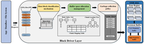
Figure 5.
The system overview of the proposed Amphisbaena.
Specifically, the data block classification component can identify the attributes of blocks based on the explicit characteristics of write requests. Then, based on the implicit characteristics of write requests, the data block classification component further assigns specific roles to blocks with different attributes. To improve the space utilization efficiency of the persistence buffer, the buffer space allocation management component divides it into a high-frequency buffer (HFB) and a low-frequency buffer (LFB). Each buffer can cope with write requests with different locality characteristics, similar to Amphisbaena’s two heads being able to move and hunt in two directions simultaneously. Moreover, as the access patterns of workloads change, the size of each buffer can be adaptively reallocated. When buffer cleanup is triggered, the garbage collection component intelligently migrates victims from the buffer to the target storage area, minimizing the latency of user requests by reducing fragmentation of the data layout within the native zone and the collection duration of victims.
The workflow of Amphisbaena for processing write requests is depicted in Figure 6. Each incoming write request is first passed to the data classifier for preprocessing ①. The space allocator then allocates the designated buffer space for these blocks based on the classified result ②, ③. If there is no buffer space available, the garbage collector is awakened ④ and the garbage collector selects victims from a specified buffer ⑤. The victim is migrated to the native zone until there is enough space to accommodate these new blocks and then stopped ⑥. Meanwhile, some messages about the victims are returned to the data classifier for making accurate classifications in the future ⑦. Compared to the complex workflow of write requests, read requests only need to collect the target blocks based on valid addresses retrieved by the space allocator from the persistence buffer or native zones.
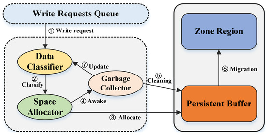
Figure 6.
The workflow of Amphisbaena for processing write requests.
5. Amphisbaena Design
In this section, we first describe the method for identifying and organizing blocks that are frequently updated and have long update periods in Section 5.1. Then, in Section 5.2, we describe how to implement a locality-aware data block layout scheme and guidelines for space allocation and resizing. The principles of the latency-sensitive garbage collection policy are described in Section 5.3. Finally, the implementation overhead and reliability issues of Amphisbaena are discussed in Section 5.4.
5.1. Two-Phase Data Block Classification
5.1.1. The Role Type of the Data Block
The data classifier is responsible for capturing and reserving frequently updated blocks for the HFB. The data classifier process of classifying blocks consists of two phases. In the first phase, the data classifier predicts the attributes of the blocks it contains based on the explicit characteristics (i.e., write size) of the current write request. This is because smaller requests present better temporal locality, in other words, are more likely to be accessed frequently in the future [41]. The prediction of block attributes is done by comparing the size of the current write request with the , where WINDOW_LENGTH is the length of the observation window containing the last N write requests. The Equation (1) is introduced to dynamically determine the size of the . If the size of the current write request is less than the current hot block threshold, then the write request contains blocks that are labeled as “hot” and vice versa. Write requests labeled as “hot” are considered to be potentially hot blocks, and all of them are reserved in the HFB. Instead, only partially qualified blocks from write requests labeled as “cold” can be reserved in the HFB. The blocks that are allowed to be loaded into the HFB are then handled further by the data classifier.
In the second phase, the write request is split into multiple 4 KB blocks and the data classifier further refines the classification of the blocks based on their implicit characteristics (i.e., update period). To accurately capture the hot data, we designed four roles based on the access characteristics of the blocks, as shown in Table 1, namely long update period (LUP) blocks, short update period (SUP) blocks, ghost blocks, and shadow blocks. Specifically, the first two types are resident blocks with data (4 KB) in the HFB, and these blocks have significantly different update periods; while the latter two types are non-resident blocks that are much smaller than the former and only record the block number (4 B). Typically, updates to SUP blocks and LUP blocks generate write hits, especially the former, which can be updated frequently due to their short update period. In contrast, ghost and shadow block hits do not yield immediate benefits, i.e., acquisition of the target data, but their presence is beneficial for the data classifier to identify blocks with long and frequent update periods, which can indirectly improve the write hit rate.

Table 1.
Detailed descriptions of the different roles.
5.1.2. Organization of Data Blocks with Roles
In a real environment, it is expensive to capture and compute the update period of each block. Inspired by the Low Inter-reference Recency Set (LIRS) algorithm [29,30], the data classifier focuses only on the most recent update information of a block (the interval between the last two updates), which requires two recency-based lists to manage the blocks of different roles separately. For this purpose, the least recently used (LRU)-based filter list and the resident list are used to organize all role blocks. With this design, the data classifier can avoid explicitly recording the update period of each resident block and the maximum value of the update period, thus achieving an acceptable computational and storage overhead.
As shown in Figure 7, each entry in the filter list and the resident list records the LBA of the role block. Note that the actual size of the HFB is determined by the number of SUP blocks and LUP blocks, where the ratio of the filter list to the HFB is , and the ratio of the resident list to the HFB is 1-. The filter list contains only LUP blocks which are the new blocks inserted into the HFB or the SUP blocks degraded from the resident list. For the former, they have no update period information, and the data classifier cannot distinguish whether they are hot blocks or not; for the latter, they have previous update period information and may be hot blocks with frequent updates but long periods, so they need to be observed further. Once an LUP block in the filter list is updated, the data classifier promotes it from the filter list to the most recently used (MRU) end of the resident list and removes its entry from the filter list. Unlike the filter list, the resident list holds the entries of all role blocks and sorts them by recency. To identify whether a data block with a short update period, the bottom of the resident list must be an sup block. In other words, it is the one with the longest update period among the SUP blocks. The data classifier reduces the cost of computing the update period of a role block by comparing the recency of the updated block to that of the bottom SUP block, rather than explicitly searching for a block with the longest update period. Please refer to Section 5.2.2 for a detailed description of the role adjustment for write-hit blocks. In addition, the number of ghost and shadow blocks in the resident list is not unlimited; their maximum update period is the update period of the last SUP block minus 1.
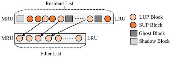
Figure 7.
A schematic diagram of the organization of the role blocks.
5.2. Locality-Aware Buffer Space Management
5.2.1. Space Layout of the Persistent Buffer
Figure 8a depicts the state of the persistent buffer at the initialization of the storage system. The space allocator divides the persistent buffer into two sub-buffers, HFB and LFB, at a default scale, and sets different granularities for their space allocation units to accommodate blocks with temporal locality characteristics and blocks with spatial locality characteristics, respectively. However, in some real-world workloads, write requests at different epochs exhibit either spatial locality or temporal locality. Fixed-size LFB and HFB make it difficult for persistent buffers to efficiently cope with write requests with different locality characteristics. Therefore, the sizes of LFB and HFB are periodically reallocated to match the current I/O access pattern of the workload. Figure 8b,c show the state of the HFB and LFB when they are reallocated.
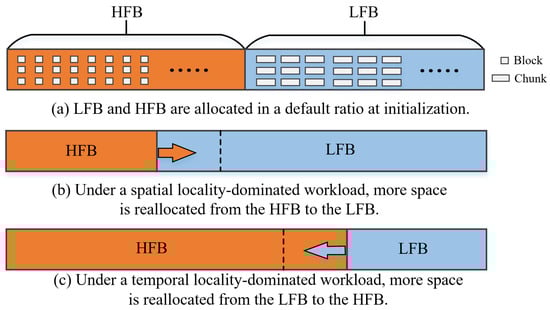
Figure 8.
The internal data layout space of the persistent buffer.
Specifically, HFB uses a block that is the same size as the physical sector of SMR disks (i.e., 4 KB) as the basic space allocation unit. The block-based allocation unit makes it easier for the space allocator to allocate space for different roles of blocks in a fully associative manner, facilitating more efficient space utilization in the HFB. Compared to the HFB, the LFB accommodates most of the new write traffic. Since coarse-grained allocation units feature stronger spatial locality, which contributes to improved I/O efficiency for large requests and cleanup activity, the chunk is used as the space allocation unit in the LFB. The space allocator dynamically allocates a chunk to any unmapped zone in a set-associative manner. As shown in Figure 9, Zone 0 consists of 256 chunks of size 1 MB, and each chunk maps 256 contiguous 4 KB block offsets within the zone. For example, chunk 0 is mapped to a contiguous address from LBA = 0 to LBA = 255 within zone 0. When the write request 1 arrives, the space allocator writes target blocks 0∼2 to chunk 0 according to the block offset in zone 0.
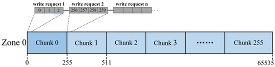
Figure 9.
An illustration of the relationship between chunk and SMR.
5.2.2. Space Allocation for the Persistent Buffer
The space allocator allocates space to blocks labeled as cold and hot blocks based on the processing results of the data classifier. For those blocks that are routed to the LFB, since each block is statically mapped to only one specific chunk, chunk-level mapping is used to maintain the mapping information of the LFB. The space allocator first locates the address of the chunk’s mapping entry based on the chunk location tree (CLT) in Figure 10a. The key of each tree node is the sum of chunk_num and zone_chunk, and the value is the address of the mapped entry. The chunk_num can be calculated by Equation (2), where and denote the number of blocks contained in a chunk and zone, respectively.
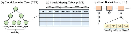
Figure 10.
An illustration of the metadata structure for HFB and LFB.
Subsequently, the space allocator updates the metadata of the specified mapping entry in the chunk mapping table (CMT) based on the returned address. As shown in Figure 10b, the CMT contains five fields, namely id, zone_num, chunk_offset, max_block_offset, and min_block_offset. Finally, blocks with cold labels are written to the appropriate chunk. Note that blocks with cold labels that already exist in the HFB are updated in their original location instead of being redirected to the chunk.
Compared to the blocks labeled as cold, the blocks labeled as hot routed to the HFB are more complicated to handle because any hit on a role block can result in a role conversion. To speed up locating the buffer blocks in the HFB, a hash-based block-level mapping as shown in Figure 10c is created, where LBA and physical block address (PBA) denote the key and value, respectively. After retrieving the metadata of a hit block, the data classifier updates the roles of the blocks in the HFB according to the changes in the update period. The following describes the detailed manipulation of a block to be updated.
- Shadow block write hit. As mentioned in Section 5.1.1, the shadow block refers to those block numbers that are labeled as cold and are not in the HFB. In fact, the data classifier must record these block numbers to correct the misclassification caused by insufficient prediction accuracy in the first phase. Otherwise, the truly hot blocks that were misclassified as cold will never have a chance to be found. When a shadow block entry is hit, it changes from a non-resident block to a resident block, and its role is changed to LUP, then the new LUP block is moved to the MRU end of the filter list, and the resident list.
- Ghost block write hit. Although ghost blocks and shadow blocks are both non-resident blocks that record historical information, there are subtle differences between them. Unlike the latter, the ghost block records the block numbers of those that have been removed from the filter list. The write hit of these blocks indicates that they have long update periods and high update frequency. Consequently, after a ghost block is updated, its role is immediately changed to SUP and moved to the MRU end of the resident list.
- LUP block write hit. Blocks loaded into HFB for the first time remain in the filter list before being hit again. When an LUP block is hit, its operation includes two cases. First, if the hit LUP block exists in both the filter list and the resident list, the hit block is removed from the filter list and inserted as an sup block at the MRU end of the resident list. Then, the SUP block at the bottom of the resident list is converted to an LUP block and moved to the LRU end of the filter list, which is called a prune operation. Meanwhile, other block entries between the old bottom SUP block and the new bottom SUP block are also removed. In the other case, the hit blocks are demoted from the resident list, indicating that the hit blocks have long update periods and are updated frequently, and the hit blocks can be added directly to the MRU end of the resident list as an sup block. Note that since the hit block previously existed only in the filter list, this does not trigger a pruning operation in the resident list.
- SUP block write hit. When an sup block is updated in the resident list, the space allocator moves it to the MRU end of the resident list. At this point, the space allocator must further check the location of the SUP block to be updated. If the SUP block to be updated is at the bottom of the resident list, the other block entries between the old bottom SUP block and the new bottom SUP block are also discarded.
Note that any blocks loaded into the HFB will be added to the resident list as SUP blocks before the resident list is full. The above is a description of how the space allocator processes the blocks with cold and hot labels, and Figure 11 visualizes the conversion flow between roles. For the read request processing flow, the space allocator only needs to search the target block in the order of HFB, LFB, and native zone.
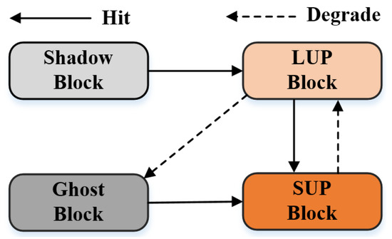
Figure 11.
The schematic diagram for the role transformation of data blocks.
5.2.3. Reallocation of the Persistent Buffer
Real-world workloads may present different locality characteristics in each period. To ensure the stability of SMR disk performance, a key issue is how to adaptively adjust the ratio of HFB and LFB according to the workload locality characteristics. For this purpose, a heuristic-based dynamic reallocation policy for the persistent buffer is designed. During system initialization, HFB and LFB are allocated in a default ratio. Subsequently, the space allocator reviews the historical access records of the HFB and LFB in each predefined sampling period to decide whether their capacity needs to be adjusted. In this way, the space allocator allocates buffer space to the HFB and LFB in the optimal ratio for the persistent buffer, allowing Amphisbaena to better adapt to the current access patterns of the workload. Figure 8b,c show the process of the data classifier reallocating space to the HFB and LFB.
To reduce the complexity and overhead of space reallocation, the chunk containing contiguous LBA space is used as the base unit for space reallocation. In addition, the size of the HFB is limited to between 25% and 75% of the persistent buffer capacity to avoid performance jitter caused by the overallocation or deallocation of space. Specifically, if the ghost blocks in the resident list are updated again within a sample period and their number exceeds the size of a chunk (i.e., the number of blocks it can hold), it means that the current capacity of the HFB is insufficient to accommodate more frequently updated blocks. In this case, the space allocator reclaims a certain number of chunks from the LFB to allocate more space to the HFB. The number of chunks deallocated from LFB is calculated by dividing the number of ghost blocks by the size of the chunks. For example, after a sampling period, the space allocator reviews the history and finds that 60 ghost blocks write hit, meaning that these blocks are frequently updated and have a long update period, so the capacity of the HFB must be reallocated to accommodate these blocks. If a chunk can hold 16 blocks, then the number of reallocated chunks is 60 divided by 16, rounded to 4. Conversely, if any block in a reallocated chunk obtained from the LFB is not updated again within a sample period, the reallocated chunk is returned to the LFB. The guidelines for data migration in the HFB and LFB can be found in Section 5.3.
5.3. Latency-Sensitive Garbage Collection
To mitigate the impact of buffer cleanup on user requests, the garbage collector uses a latency-sensitive garbage collection policy to schedule cleanup activities in the LFB and HFB. This policy reduces the cost of buffer cleanup in three ways: using different cleanup patterns for the LFB and HFB, splitting the garbage collection process, and detecting write requests to victims.
The LFB cleanup. As the entry for blocks into the persistent buffer and the only exit for blocks to the native zone, the LFB experiences most of the write traffic. Therefore, the cleanup efficiency of the LFB has a direct impact on user request latency. Although the garbage collector can use the inter-request interval to actively schedule LFB cleanup to reduce the time of blocked user requests, in I/O-intensive workloads, there is not enough free interval to complete a large-scale zone-level garbage collection. To balance user request latency and write amplification, the garbage collector splits the victim zone collection process into multiple stages at chunk granularity. When collecting victim blocks, if the garbage collector detects write requests for the current victim in the I/O request queue, it stops collecting at the next completion checkpoint and writes the victim back to the native zone as soon as possible. Note that we do not use a log to redirect incoming data, not only to reduce the subsequent data synchronization overhead but more importantly, because incoming write requests may update the victim, which means that the write-back data is invalid.
In addition, the garbage collector takes their spatial locality into account when selecting victims. This is because the victim blocks merge with the old cluster to form a new cluster, and the strength of their spatial locality determines the current fragmentation level of the native zone. If the distribution of blocks in the new cluster is fragmented, it increases the probability of triggering RMW when future victims are written back. In practice, a fragmented block layout also increases the time it takes to collect blocks in the native zone during RMW. Therefore, a new metric called fragmentation level (FL) is introduced to quantify the spatial locality of a victim. The fragmentation level of a victim is calculated by Equation (3), where native_block and write pointer (wp) denote a block and the block pointed to by the write pointer in the native zone, respectively, and victim block (vb) denotes a block in the LFB. Finally, the weight of the victim is calculated according to Equation (4), where chunk_cnt is the number of chunks contained in the victim.
The HFB cleanup. Most of the resident blocks in the HFB are frequently updated blocks, so the garbage collector must delay the HFB clean up as much as possible to prevent the hot blocks from moving back and forth between the persistent buffer and the native zones. Consequently, the garbage collector will only passively schedule the HFB cleanup process when the resource in the HFB is exhausted. As described in Section 5.1, the filter list is the only exit for blocks leaving the HFB. When the HFB buffer cleanup process is triggered, the garbage collector searches for victims from the LRU end of the filter list. The number of evicted victims in the HFB is related to the presence of a mapped chunk in the LFB. That is, if the corresponding chunk already exists in the LFB, the garbage collector evicts only one block at a time; conversely, blocks belonging to the same chunk in the filter list are evicted in bulk to make full use of the chunk’s storage space. Finally, victims from the HFB are redirected to the chunk in the LFB. The above measures not only reduce unnecessary RMW operations triggered by hot block writes but also strengthen the spatial locality of the chunk, which effectively reduces the write amplification.
5.4. Overhead and Reliability Analysis
This section discusses the space and time overhead of Amphisbaena and how to ensure data consistency in the event of a power failure.
Space and time overhead. As shown in Figure 10, different data structures are used to organize metadata in the HFB and LFB, which inevitably introduces some space and time overhead. As described in Section 5.2.2, block-level mapping and chunk-level mapping are used to manage the address mapping information of HFBs and LFBs. In addition, the bitmap is used to keep track of the validity of the blocks in a chunk. As mentioned in Section 5.2.3, the size of the HFB is limited to 25% to 75% of the total persistent buffer capacity. Therefore, for a system with 64-bit addressing, given chunk size = 64 KB and block size = 4 KB, the block-level and chunk-level metadata space overhead with per-GB persistent buffer is at most 29 KB and 4 MB, respectively. In a real environment, while the memory consumption of metadata is proportional to the size of the persistent buffer specified for initialization, this can be flexibly adjusted at runtime depending on the resource utilization of the system. For example, with a small persistence buffer, all metadata can be loaded into memory; conversely, with a large persistence buffer, limited system resources allow only some of the most frequently accessed metadata to be loaded into memory. In terms of the time overhead, HFB and LFB use hash and a balanced binary search tree to locate the mapping information of the target block, and their time overheads are O(1) and O(log(n)), respectively, where n is positively correlated with the number of chunks.
Reliability. Storing metadata in the RAM space can speed up response to the I/O requests, so the metadata is loaded into the cache on demand. In the event of a power failure, metadata that has not been synchronized promptly will be lost, resulting in data inconsistency issues. This requires periodic synchronization of metadata in memory with the CMR zones on the disk. Today, many advanced solutions can be used to ensure data consistency, such as write-ahead logs or the use of small non-volatile memory (NVM), which can be used to ensure data consistency. Designing metadata caching strategies and data consistency strategies is beyond the scope of this paper, and we will focus on these issues in the future.
6. Experiment
6.1. Experimental Setup
The prototype system of Amphisbaena is implemented in user space [22,33], log and its space allocation component and garbage collection component use the relevant functions provided by the open-source library libzbc [42] to interact with a real HM-SMR disk. The detailed parameters of the HM-SMR disk are listed in Table 2. All experimental evaluations were performed in a Ubuntu 20.04.1 environment configured with a 5.15.0 Linux kernel, with a workstation equipped with a 3.0 GHz AMD EPYC 7302 CPU and 128 GB DRAM.
Table 2.
Specifications of the SMR Disk.
Since RMW operations in persistent buffer cleanup are the root cause of SMR disk performance jitter, a set of write-request dominated workloads from Microsoft Research Cambridge [17,43] is selected to evaluate the effectiveness of the proposed strategy. The detailed characteristics of the trace, as shown in Table 3, include the number of requests, write ratio, update ratio, write range, and average write size. Note that some additional features that affect the accuracy of the experimental evaluation results, such as read-ahead, read-lookahead, and write-cache, are disabled. Regarding the observation window mentioned in Section 5.1.1, we refer to the literature [41] to set its size to 1024. In addition, the sampling period in Section 5.2.3 is set to 10,000, which means that for every 10,000 write requests, the space allocator will check if the buffer space needs to be reallocated. To avoid overestimating the effect of the strategy, we dynamically set the size of the persistent buffer to 1% of the maximum access range of the trace, based on the study [6,16]. The representative strategies chosen to compete with Amphisbaena are shown below:
Table 3.
Characteristics of evaluated workloads.
- Fluid [16] uses a circular log data layout to manage the persistent buffer. All incoming blocks are sequentially appended to the end of the log and can be updated in place. When the buffer is cleaned, the victim is evicted in a FIFO manner.
- Fluid_loop [16] follows the same data layout scheme as Fluid. The difference is that when the buffer is cleaned, the hot-zone blocks are re-queued to the head of the log instead of being written back.
- Skylight [6] uses a hash algorithm to map SMR zones to a specified buffer zone, which is a typical persistent buffer management strategy that can be used for CMR- or SMR-based persistent buffers. All incoming data is sequentially appended to a specified buffer zone, and when the buffer is cleaned, all buffered blocks in a CMR zone are written back to their native zone.
6.2. Performance Evaluation
In this section, we evaluate the effect of Amphisbaena with chunk = 64 KB and = 0.1, and other state-of-the-art persistent buffer management strategies on improving disk performance. Average response latency, write buffer hit rates, number of RMW and RMW-free, write amplification, padded data volume, and average write-back victim zone size are used to comprehensively evaluate the efficiency of Amphisbaena. The X-axis of each graph represents different workloads and the Y-axis represents specific metrics.
Normalized average response latency. We first compare the average I/O response latency of Amphisbaena with that of the adversary to evaluate the overall performance improvement of the disk. The response latency under all traces is normalized to Amphisbaena, and the experimental results are shown in Figure 12. It can be observed that Amphisbaena reduces the response latency by a maximum of 82.4% and a minimum of 4.8% compared to Fluid_loop (i.e., in traces src2_2 and src2_0). These two traces are the spatial locality-dominated and the temporal locality-dominated workloads, respectively. One of the reasons Amphisbaena can achieve I/O performance improvements is that the space allocator uses a custom buffer management unit to manage each buffer, effectively balancing the cleanup and writing efficiency. The ability to dynamically adjust the size of each buffer as the workload changes is another reason. In addition, the latency-sensitive garbage collection policy is also beneficial in reducing the time user requests that are blocked.
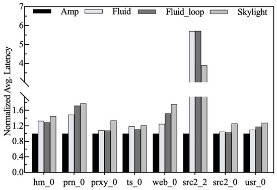
Figure 12.
Normalized average response latency.
Write hit rates. Write hit rates represent the ratio of the number of buffered blocks updated to the total number of blocks written. The higher the write hit rate, the less frequently the buffer is cleaned, which contributes to stable SMR disk I/O performance. It is important to note that Amphisbaena’s overall hit rate consists of two parts. As shown in Figure 13, the HFB hit rate is represented by the black bar at the bottom, and the LFB hit rate is represented by the white bar at the top. Compared to Fluid and Skylight, Fluid_loop re-queues hot blocks in victims to the head of the log queue to avoid premature eviction, and thus its write-hit rate outperforms both in most traces. Benefiting from the efficiency of the two-phase block classification scheme, the write-hit rate of Amphisbaena is higher than that of its competitors in all traces. In particular, in src2_2, where spatial localization dominates, the write-hit rate of Amphisbaena is at least 5.8% higher than that of Skylight which achieves the suboptimal result.
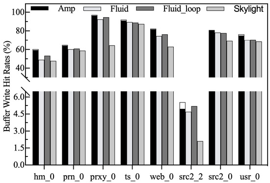
Figure 13.
Write hit rates.
Normalized write amplification. As shown in Figure 14, Amphisbaena exhibits the lowest write amplification under all workloads, with an average reduction of 98.5% compared to other strategies. The reason behind this is that Amphisbaena utilizes fragmentation-level metrics to reduce the formation of fragmented data layouts, thereby reducing redundant RMW operations and achieving lower write amplification. While Skylight requires each CMR zone to hold data from multiple SMR zones, this triggers multiple RMW operations during the cleanup process, increasing the likelihood of write amplification. Unlike Skylight, both Fluid and Fluid_loop follow the FIFO principle during the cleanup, so they cannot select victims based on data layout characteristics, which is the main reason for their higher write amplification.
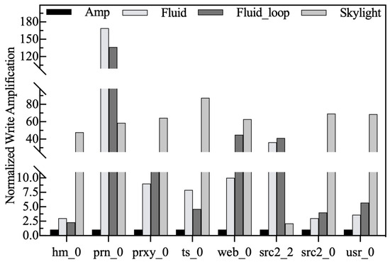
Figure 14.
Normalized write amplification.
RMW and RMW-free counts. Figure 15 shows the effect of Amphisbaena in reducing RMW operations. As confirmed in the literature [21,22], the number of RMW operations is a key factor affecting the overall performance of SMR disks. Therefore, reducing the number of RMWs is an effective way to improve disk performance. As shown in Figure 15, the bottom of each bar indicates the number of RMW operations involved in write-backs, and the top bar indicates the number of write-backs that are not involved in RMW operations (also known as RMW-free), so the sum of the two indicates the total number of write-backs. From the results, it is clear that Amphisbaena not only has the lowest number of RMW operations but also the total number of write-backs is lower than the other competitors. Unlike other competitors that lack data layout awareness, our victim selection policy takes into account the impact of victims on the native zone’s spatial locality, which is the key to eliminating unnecessary RMW operations. As a result, Amphisbaena can reduce RMW operations by an average of 37%.
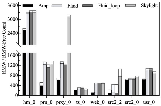
Figure 15.
RMW and RMW-Free counts.
Padding data volume. Since the sequential write constraint of SMR disks causes blocks to be appended sequentially only at the location of the write pointer, synthetic data are used to fill the gap between valid blocks. In fact, the amount of synthetic data introduced during data migration affects the spatial locality of the native zone. Avoiding too much synthetic data as much as possible can effectively reduce RMW operations during cleanup. In addition, the excessive synthetic data written back inevitably occupy the internal bandwidth of the disk, thus increasing the response latency of user requests. From Figure 16, we can clearly see that Amphisbaena introduces the least amount of synthetic data among all the traces. For example, Amphisbaena can reduce synthetic data by up to 552 GB and 191 GB under src2_2 and prxy_0, two workloads with strong spatial locality and strong temporal locality, respectively.
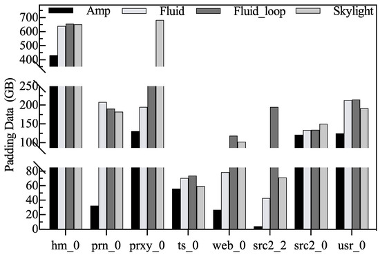
Figure 16.
The amount of padded synthetic data.
Average victim zone size. A larger victim zone size means that it has a stronger spatial locality that can reduce the write amplification. The average victim zone size is the total number of buffer blocks evicted each time divided by the number of zones involved in the cleanup. The garbage collector selects a larger victim zone to make better use of the sequential write capability of the disk and to reduce the seek time during garbage collection. In addition, if the number of blocks to be evicted is certain, the larger the zone size, the fewer RMW operations are introduced and the cleanup time is shorter. Figure 17 shows the average victim zone size. Except for the ts_0 and src2_0 workloads, the size of the evicted victim zone in Amphisbaena is the largest. There are two reasons for this: some of the hot blocks are reserved in the HFB, which makes it difficult to form a larger victim zone in the LFB; on the other hand, the latency-sensitive garbage collection policy aborts the collection process at the next checkpoint if it detects the write request against the current victim zone, resulting in only some of the blocks in the victim zone being write-back.
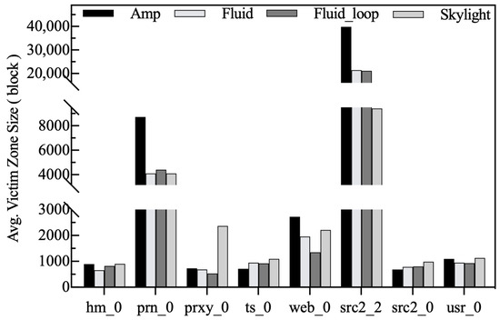
Figure 17.
Average victim zone size.
6.3. Performance Evaluation with the Different-Sized Chunk
To evaluate the impact of different chunk sizes on system performance, we adjust the chunk size from 64 KB to 1024 KB to observe the variation of each metric. In addition to the basic metrics mentioned in Section 6.2, the size of the space reallocated by the space allocator for the HFB and LFB is shown.
Normalized Average Response Latency. All results are normalized to the response latency by chunk = 64 KB. As shown in Figure 18, the response latency increases gradually with chunk size for most traces. By analyzing the traces, we find that their average write requests are small, and increasing the chunk size results in lower space utilization in the LFB. The limited number of chunks and lower space utilization are the reasons for the increased number of LFB cleanups. The astute reader will notice that Amphisbaena’s I/O latency under src2_2 gradually decreases as the chunk size increases. Note that src2_2 is a spatial locality-dominated workload, it contains many write requests with larger sizes, which contributes to improving the space utilization of a chunk. Therefore, the I/O latency for such workloads gradually decreases as the chunk size increases. Although a larger chunk size under src2_2 is beneficial for improving the write efficiency and reducing garbage collection time, the space utilization of the chunk decreases when its size exceeds a certain threshold. For example, the response latency under src2_2 starts to increase at chunk = 256 KB. The reason for this, as described above, is that a larger chunk increases the frequency of buffer cleanup, resulting in an increase in latency.
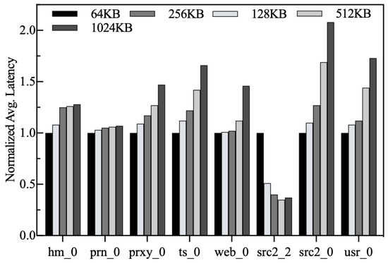
Figure 18.
Normalized average response latency.
Write hit rates. As described in Section 5.2, the top and bottom of the bars indicate the write hits of the LFB and HFB, respectively. Figure 19 shows the variation of the write hit rate for different chunk sizes. We can see that the write hit rate is not sensitive to the chunk size. Although a larger chunk size potentially increases the cleaning frequency in the LFB, it does not affect the HFB. We can see from the results that the write hits are mainly contributed by the HFB, while the LFB is only used as a temporary storage for cold blocks. The space allocator does not reduce the size of the HFB, even though the number of free blocks is limited. Therefore, most of the hot blocks remain in the HFB. Overall, increasing the chunk size does not significantly reduce write-hit rates.
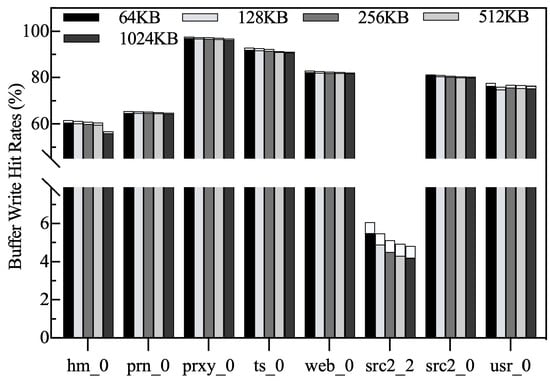
Figure 19.
Write hit rates.
Normalized write amplification. As shown in Figure 20, all results are normalized to chunk = 64 KB. It is clear that write amplification increases gradually with chunk size, except for src2_2. On the one hand, increasing the chunk size causes the LFB to be cleaned more frequently. On the other hand, if the gap between the chunk size and the average size of write requests is larger, the chunk may also be evicted before it is fully filled. The above factors are the reasons why increasing the chunk size leads to out-of-controllable write amplification. Also, most of the write requests in src2_2 are out of order, but Amphisbaena’s eviction policy causes the victims to be written back to the native zone in an organized way, thus eliminating write amplification.
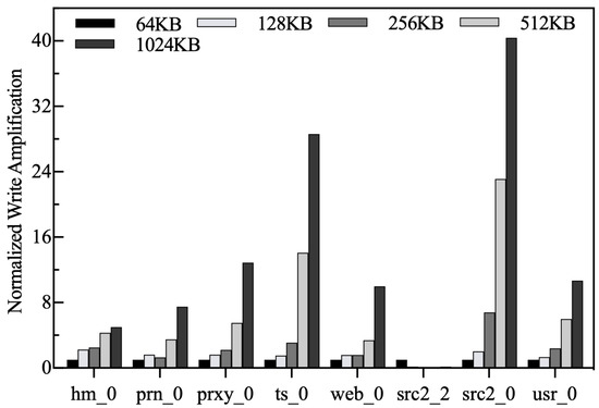
Figure 20.
Normalized write amplification.
RMW and RMW-free counts. We record the number of RMWs for different chunk sizes and normalize all results to chunk = 64 KB. As shown in Figure 21, the larger the chunk size, the higher the number of RMWs. As the chunk size increases, the number of free chunks gradually decreases. Although the space allocator adjusts the space size of the LFB accordingly, the number of free chunks is still limited. Since the LFB is the only exit from the buffer, it must be cleaned frequently to ensure that there is enough space for new chunks, resulting in an increase in the number of RMWs. The reasons why the number of RMWs on src2_2 decreases as the chunk size increases are the same as described above.
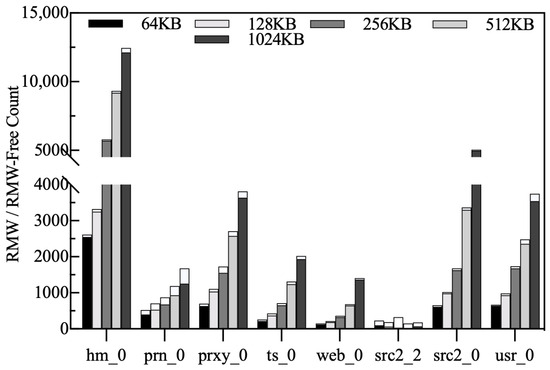
Figure 21.
RMW and RMW-free counts.
Normalized padding data volume. Figure 22 shows the trend in the amount of synthetic data padded for different chunk sizes, and all results are normalized to the chunk = 64 KB result. As can be seen from the figure, for workloads other than src2_2, the growth trend in the amount of synthetic data is consistent with the write amplification rate and the frequency of RMW operations, both of which are positively correlated with chunk size. For example, combining Figure 3 with Table 3 shows that hm_0 has a wide range of write request accesses and a small average write size, and thus introduces the most synthetic data. The src2_2 has a significantly higher write volume than the other workloads and a lower update frequency, which uses the chunk space more efficiently and therefore introduces the lowest amount of synthetic data.
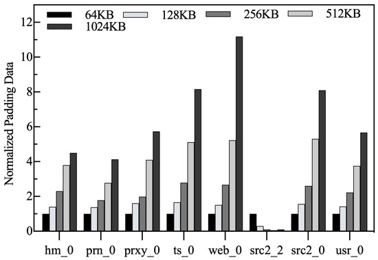
Figure 22.
Normalized amount of padded synthetic data.
Normalized average victim zone size. Figure 23 shows the variation in the average victim zone size. We normalize all results to chunk = 64 KB. For most workloads, the average victim zone size decreases as the chunk size increases. This is attributed to the fact that as the number of chunks available in the LFB decreases, most of the chunks are evicted without accumulating enough buffer blocks, making it difficult to form larger victims. For src2_2, which features significant spatial locality, the average size of the victim zone is maximized when chunk = 128 KB. After that, increasing the chunk further causes the average size of the victim zone to gradually decrease. This indicates that chunk utilization is highest when the size is set to 256 KB, which makes maximum use of the sequential write capability of the disk.
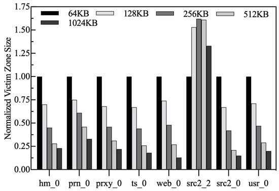
Figure 23.
Normalized average victim zone size.
Persistent buffer reallocation. To adapt to changes in workload access patterns, space in the HFB and LFB is periodically reallocated. Because a chunk in the LFB represents a set of contiguous LBAs in the zone, migrating it to the native zone does not involve multiple read/write operations. On the contrary, a block within a chunk in the HFB can come from several different zones, and its migration requires multiple reads and writes. In summary, if the HFB space is too large, subsequent space adjustments can add significant migration costs. Therefore, at system initialization, the HFB is set to 25% of the total persistent buffer size, and the rest of the space is allocated to the LFB. As shown in Figure 24, the bottom and top of the bar indicate the size of the reallocated space for HFB and LFB, respectively. It can be observed that the space of HFB is adjusted more than that of LFB in most of the traces. This is because HFB is given a smaller space at the beginning of the system, and HFB needs to be allocated more space to accommodate the hot blocks. Under web_0 and src2_2, there is less variation in space allocation, indicating that each buffer is well adapted to the access pattern of the workload at different stages.
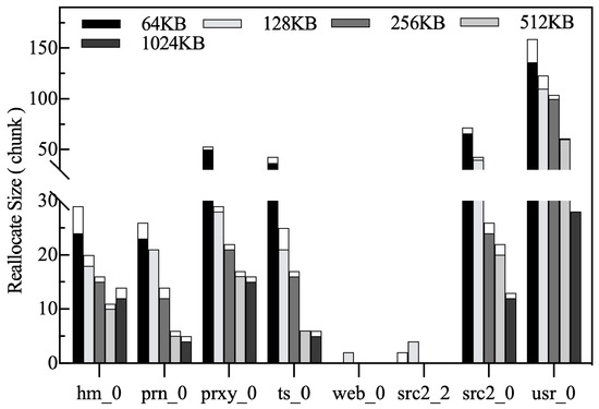
Figure 24.
Number of chunks reallocated for the HFB and LFB.
6.4. Performance Evaluation with Different Filter List Ratios
The write hit rate results in Section 6.2 and Section 6.3 show that the write hit rate of the HFB dominates the overall write hit rate of the persistent buffer. In the HFB, the ratio of the resident list size to the HFB size (i.e., 1) is related to the number of SUP blocks. Under most workloads, SUP blocks have shorter update periods and a higher probability of being accessed compared to LUP blocks, which means that more SUP blocks contribute to higher write-hit rates. To this end, we have designed a series of experiments to demonstrate the impact of different values of on system performance. It should be noted that the setting directly affects the HFB hit rate, and I/O response latency is the result of the overall effect of various factors, so it is used as the reprensentive performance metric.
Theoretically, as gradually increases, more and more blocks in the HFB have the opportunity to be selected as victims, which inevitably leads to the eviction of some hot blocks, while a smaller allows blocks that are on the list to stay longer and thus generate more write hits. Figure 25 shows the sensitivity study of write hit rates and I/O response latency for = 0.1, 0.3, and 0.5, respectively. To our surprise, the write hit rate and I/O response latency are not sensitive to for most workloads. Our careful analysis of this phenomenon reveals that while reducing makes it easy to evict blocks from the HFB, the victims may remain in the resident list as ghost blocks until they are actively discarded by the data classifier. When the ghost blocks are updated again, they are returned to the resident list. The space allocator adaptively resizes the HFB to accommodate more blocks, which to some extent avoids the eviction of hot blocks. Also, as increases, the overhead of the garbage collector searching for victims in the filter list increases. Therefore, in terms of overall results, the best performance is achieved at = 0.1.
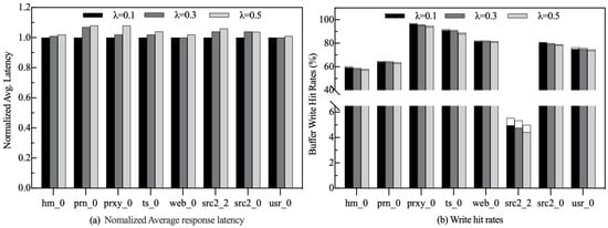
Figure 25.
Performance evaluation with different ratios.
7. Conclusions
SMR disks are expected to be an essential component in future mass data storage systems due to their low cost and high capacity. This paper proposes a CMR-based persistent buffer management strategy called Amphisbaena that can effectively improve the I/O performance of SMR disks under write-intensive workloads. First, a two-phase data block classification method is proposed, which can effectively capture blocks with frequent updates and long update periods, thus reducing redundant RMW operations. Second, a locality-aware buffer space management mechanism is introduced, which achieves a balance between cleaning efficiency and space utilization by dynamically managing buffer blocks with different locality characteristics. Finally, a latency-sensitive garbage collection mechanism is designed to reduce the queuing time of user requests by employing a customized cleanup pattern, splitting the garbage collection process, and detecting write requests to victims. The experimental results are encouraging, the proposed strategy reduces the average I/O latency by 29.9% and RMW operations by 37% compared to the current state-of-the-art strategy.
Although Amphisbaena has improved the write performance of SMR disks by reducing redundant RMW operations, it still suffers from the following limitations: Firstly, Amphisbaena is designed for write-intensive or read–write-balanced workloads, for read-intensive workloads, it fails to reduce the latency of response to hot-read data. Secondly, when the capacity of the persistent buffer is considerably large, recording the ghost blocks and shadow blocks incurs more memory overhead. With the popularity of high-performance non-volatile storage devices, using them to selectively cache hot-read data and metadata is a cost-effective solution to the above problems. Therefore, we propose to leave effective designs for future work to further increase the versatility of SMR disks in different application scenarios.
Author Contributions
Conceptualization, C.Z.; methodology, C.Z. and F.Y.; software, C.Z. and F.Y.; validation, C.Z., S.N., S.L. and W.T.; formal analysis, C.Z., S.N., S.L. and W.T.; investigation, C.Z., S.N., S.L. and W.T.; resources, C.Z., W.W. and F.L.; data curation, C.Z. and F.Y.; writing—original draft preparation, C.Z.; writing—review and editing, C.Z., S.N. and W.T.; visualization, C.Z. and F.Y.; supervision, F.L. and W.W.; project administration, S.L., W.W. and F.L.; funding acquisition, S.L., S.N., W.W. and F.L. All authors have read and agreed to the published version of the manuscript.
Funding
This research was funded by the National Natural Science Foundation of China (No. 61972311, 62202368), partially by ByteDance Inc (No. PJ20220608900030) and Shandong Provincial Natural Science Foundation (No. ZR2021LZH009).
Institutional Review Board Statement
Not applicable.
Informed Consent Statement
Not applicable.
Data Availability Statement
The original contributions presented in the study are included in the article, further inquiries can be directed to the corresponding authors.
Conflicts of Interest
Authors Wei Tang and Fei Liu were employed by the company ByteDance Inc. The remaining authors declare that the research was conducted in the absence of any commercial or financial relationships that could be construed as a potential conflict of interest.
References
- Feldman, T.; Gibson, G. Shingled magnetic recording: Areal density increase requires new data management. Login Mag. USENIX SAGE 2013, 38, 22–30. [Google Scholar]
- Amer, A.; Long, D.D.; Miller, E.L.; Paris, J.F.; Schwarz, S.T. Design issues for a shingled write disk system. In Proceedings of the IEEE 26th Symposium on Mass Storage Systems and Technologies (MSST), Incline Village, NV, USA, 3–7 May 2010; pp. 1–12. [Google Scholar]
- Cassuto, Y.; Sanvido, M.A.; Guyot, C.; Hall, D.R.; Bandic, Z.Z. Indirection systems for shingled-recording disk drives. In Proceedings of the IEEE 26th Symposium on Mass Storage Systems and Technologies (MSST), Incline Village, NV, USA, 3–7 May 2010; pp. 1–14. [Google Scholar]
- Hall, D.; Marcos, J.H.; Coker, J.D. Data handling algorithms for autonomous shingled magnetic recording hdds. IEEE Trans. Magn. 2012, 48, 1777–1781. [Google Scholar] [CrossRef]
- Greaves, S.; Kanai, Y.; Muraoka, H. Shingled Recording for 2–3 Tbit/in2. IEEE Trans. Magn. 2009, 45, 3823–3829. [Google Scholar] [CrossRef]
- Aghayev, A.; Shafaei, M.; Desnoyers, P. Skylight—A window on shingled disk operation. ACM Trans. Storage 2015, 11, 1–28. [Google Scholar] [CrossRef]
- Wu, F.; Fan, Z.; Yang, M.C.; Zhang, B.; Ge, X.; Du, D.H. Performance evaluation of host aware shingled magnetic recording (HA-SMR) drives. IEEE Trans. Comput. 2017, 66, 1932–1945. [Google Scholar] [CrossRef]
- Shafaei, M.; Hajkazemi, M.H.; Desnoyers, P.; Aghayev, A. Modeling drive-managed smr performance. ACM Trans. Storage 2017, 13, 1–22. [Google Scholar] [CrossRef]
- Ma, C.; Shen, Z.; Han, L.; Shao, Z. RMW-F: A design of RMW-free cache using built-in NAND-flash for SMR storage. ACM Trans. Embed. Comput. Syst. (TECS) 2019, 18, 1–18. [Google Scholar] [CrossRef]
- Ma, C.; Zhou, Z.; Wang, Y.; Wang, Y.; Mao, R. MU-RMW: Minimizing unnecessary RMW operations in the embedded flash with SMR disk. In Proceedings of the Design, Automation & Test in Europe Conference & Exhibition (DATE), Antwerp, Belgium, 14–23 March 2022; pp. 490–495. [Google Scholar]
- Ma, C.; Shen, Z.; Wang, Y.; Shao, Z. Alleviating hot data write back effect for shingled magnetic recording storage systems. IEEE Trans. Comput. Aided Des. Integr. Circuits Syst. 2018, 38, 2243–2254. [Google Scholar] [CrossRef]
- Liang, Y.P.; Chen, S.H.; Chang, Y.H.; Lin, Y.C.; Wei, H.W.; Shih, W.K. Mitigating write amplification issue of SMR drives via the design of sequential-write-constrained cache. J. Syst. Archit. 2019, 99, 101634. [Google Scholar] [CrossRef]
- Yang, M.C.; Chang, Y.H.; Wu, F.; Kuo, T.W.; Du, D.H. On improving the write responsiveness for host-aware SMR drives. IEEE Trans. Comput. 2018, 68, 111–124. [Google Scholar] [CrossRef]
- Le Moal, D. Dm-Zoned: Zoned Block Device Device Mapper. Available online: https://lwn.net/Articles/714387/ (accessed on 1 January 2024).
- Hajkazemi, M.H.; Abdi, M.; Desnoyers, P. μCache: A mutable cache for SMR translation layer. In Proceedings of the 28th International Symposium on Modeling, Analysis, and Simulation of Computer and Telecommunication Systems (MASCOTS), Nice, France, 17–19 November 2020; pp. 1–8. [Google Scholar]
- Wu, F.; Li, B.; Du, D.H. Fluidsmr: Adaptive management for hybrid smr drives. ACM Trans. Storage 2021, 17, 1–30. [Google Scholar] [CrossRef]
- SNIA IOTTA Repository: MSR Cambridge Block I/O Traces. Available online: http://iotta.cs.hmc.edu/traces/388 (accessed on 1 January 2024).
- Chen, C.H.; Chen, S.H.; Liang, Y.P.; Chen, T.Y.; Hsu, T.s.; Wei, H.W.; Shih, W.K. Facilitating external sorting on SMR-based large-scale storage systems. Future Gener Comput. Syst. 2021, 116, 333–348. [Google Scholar] [CrossRef]
- Wang, C.; Wang, D.; Chai, Y.; Wang, C.; Sun, D. Larger cheaper but faster: SSD-SMR hybrid storage boosted by a new SMR-oriented cache framework. In Proceedings of the IEEE Symp. Mass Storage Syst. Technol.(MSST), Santa Clara, CA, USA, 15–19 May 2017; pp. 1–16. [Google Scholar]
- Wu, F.; Li, B.; Cao, Z.; Zhang, B.; Yang, M.H.; Wen, H.; Du, D.H. ZoneAlloy: Elastic Data and Space Management for Hybrid SMR Drives. In Proceedings of the 11th USENIX Workshop on Hot Topics in Storage and File Systems (HotStorage 19), Renton, WA, USA, 8–9 July 2019. [Google Scholar]
- Sun, D.; Chai, Y. SAC: A co-design cache algorithm for emerging SMR-based high-density disks. In Proceedings of the Twenty-Fifth International Conference on Architectural Support for Programming Languages and Operating Systems, Lausanne, Switzerland, 16–20 March 2020; pp. 1047–1061. [Google Scholar]
- Sun, D.; Tan, R.; Chai, Y. A Universal SMR-Aware Cache Framework with Deep Optimization for DM-SMR and HM-SMR Disks. ACM Trans. Storage 2023, 19, 1–35. [Google Scholar] [CrossRef]
- Lee, D.; Choi, J.; Kim, J.H.; Noh, S.H.; Min, S.L.; Cho, Y.; Kim, C.S. On the existence of a spectrum of policies that subsumes the least recently used (LRU) and least frequently used (LFU) policies. In Proceedings of the ACM SIGMETRICS international conference on Measurement and modeling of computer systems, Atlanta, GA, USA, 1–4 May 1999; pp. 134–143. [Google Scholar]
- Robinson, J.T.; Devarakonda, M.V. Data cache management using frequency-based replacement. In Proceedings of the ACM SIGMETRICS conference on Measurement and modeling of computer systems, Univ. of Colorado, Boulder, CO, USA, 22–25 May 1990; pp. 134–142. [Google Scholar]
- Zhou, Y.; Philbin, J.; Li, K. The Multi-Queue Replacement Algorithm for Second Level Buffer Caches. In Proceedings of the USENIX Annual Technical Conference, Boston, MA, USA, 25–30 June 2001; pp. 91–104. [Google Scholar]
- O’neil, E.J.; O’neil, P.E.; Weikum, G. The LRU-K page replacement algorithm for database disk buffering. ACM Sigmod Rec. 1993, 22, 297–306. [Google Scholar] [CrossRef]
- Shasha, D.; Johnson, T. 2Q: A low overhead high performance buffer management replacement algoritm. In Proceedings of the 20th International Conference on Very Large Databases, San Francisco, CA, USA, 12–15 September 1994; pp. 439–450. [Google Scholar]
- Park, S.; Park, C. FRD: A filtering based buffer cache algorithm that considers both frequency and reuse distance. In Proceedings of the 33rd IEEE International Conference on Massive Storage Systems and Technology (MSST), Santa Clara, CA, USA, 15–19 May 2017; pp. 1–12. [Google Scholar]
- Jiang, S.; Zhang, X. Making LRU friendly to weak locality workloads: A novel replacement algorithm to improve buffer cache performance. IEEE Trans. Comput. 2005, 54, 939–952. [Google Scholar] [CrossRef]
- Jiang, S.; Zhang, X. LIRS: An efficient low inter-reference recency set replacement policy to improve buffer cache performance. ACM SIGMETRICS Perform. Eval. Rev. 2002, 30, 31–42. [Google Scholar] [CrossRef]
- Li, C. DLIRS: Improving low inter-reference recency set cache replacement policy with dynamics. In Proceedings of the 11th ACM International Systems and Storage Conference, Haifa, Israel, 4–6 June 2018; pp. 59–64. [Google Scholar]
- Xie, X.; Yang, T.; Li, Q.; Wei, D.; Xiao, L. Duchy: Achieving both SSD durability and controllable SMR cleaning overhead in hybrid storage systems. In Proceedings of the 47th International Conference on Parallel Processing, Eugene, OR, USA, 13–16 August 2018; pp. 1–9. [Google Scholar]
- Xie, X.; Xiao, L.; Du, D.H. Zonetier: A zone-based storage tiering and caching co-design to integrate ssds with smr drives. ACM Trans. Storage 2019, 15, 1–25. [Google Scholar] [CrossRef]
- Xiao, W.; Dong, H.; Ma, L.; Liu, Z.; Zhang, Q. HS-BAS: A hybrid storage system based on band awareness of shingled write disk. In Proceedings of the IEEE 34th International Conference on Computer Design (ICCD), Scottsdale, AZ, USA, 3–5 October 2016; pp. 64–71. [Google Scholar]
- Zheng, X.; Zhang, C.; Duan, K.; Wu, W.; Yan, J. SLA: A cache algorithm for SSD-SMR storage system with minimum RMWs. In Proceedings of the International Conference on Algorithms and Architectures for Parallel Processing, Virtual Event, 3–5 December 2021; pp. 587–601. [Google Scholar]
- Yang, T.; Wu, H.; Huang, P.; Zhang, F. A shingle-aware persistent cache management scheme for DM-SMR disks. In Proceedings of the IEEE International Conference on Computer Design (ICCD), Boston, MA, USA, 5–8 November 2017; pp. 81–88. [Google Scholar]
- Ma, C.; Wang, Y.; Shen, Z.; Shao, Z. KFR: Optimal cache management with K-framed reclamation for drive-managed SMR disks. In Proceedings of the 57th ACM/IEEE Design Automation Conference (DAC), San Francisco, CA, USA, 20–24 July 2020; pp. 1–6. [Google Scholar]
- Zhang, B.; Yang, M.H.; Xie, X.; Du, D.H. Idler: I/O workload controlling for better responsiveness on host-aware shingled magnetic recording drives. IEEE Trans. Comput. 2020, 69, 777–788. [Google Scholar] [CrossRef]
- Pan, Y.; Jia, Z.; Shen, Z.; Li, B.; Chang, W.; Shao, Z. Reinforcement learning-assisted cache cleaning to mitigate long-tail latency in DM-SMR. In Proceedings of the 58th ACM/IEEE Design Automation Conference (DAC), San Francisco, CA, USA, 5–9 December 2021; pp. 103–108. [Google Scholar]
- Ma, C.; Zhou, Z.; Wang, Y.; Wang, Y.; Mao, R. MAID-Q: Minimizing Tail Latency in Embedded Flash With SMR Disk via-Learning Model. IEEE Trans. Comput. Aided Des. Integr. Circuits Syst. 2022, 41, 3709–3720. [Google Scholar] [CrossRef]
- Lin, H.; Li, J.; Sha, Z.; Cai, Z.; Shi, Y.; Gerofi, B.; Liao, J. Adaptive Management with Request Granularity for DRAM Cache inside NAND-based SSDs. IEEE Trans. Comput. Aided Design Integr. Circuits Syst. 2022, 42, 2475–2487. [Google Scholar] [CrossRef]
- Western Digita. Libzbc Version 5.13.0. Available online: https://github.com/westerndigitalcorporation/libzbc (accessed on 1 January 2024).
- Narayanan, D.; Donnelly, A.; Rowstron, A. Write off-loading: Practical power management for enterprise storage. ACM Trans. Storage 2008, 4, 1–23. [Google Scholar] [CrossRef]
Disclaimer/Publisher’s Note: The statements, opinions and data contained in all publications are solely those of the individual author(s) and contributor(s) and not of MDPI and/or the editor(s). MDPI and/or the editor(s) disclaim responsibility for any injury to people or property resulting from any ideas, methods, instructions or products referred to in the content. |
© 2024 by the authors. Licensee MDPI, Basel, Switzerland. This article is an open access article distributed under the terms and conditions of the Creative Commons Attribution (CC BY) license (https://creativecommons.org/licenses/by/4.0/).