Article

Performance Estimate of a Spin-Stabilized Drag Sail for Spacecraft Deorbiting

Department of Civil and Industrial Engineering, University of Pisa, 56122 Pisa, Italy
*
Author to whom correspondence should be addressed.
Appl. Sci. 2024, 14(2), 612; https://doi.org/10.3390/app14020612
Submission received: 17 November 2023 / Revised: 4 January 2024 / Accepted: 8 January 2024 / Published: 10 January 2024
(This article belongs to the Special Issue Advances in Space Traffic Management)

Abstract

:
The growing amount of space debris in geocentricorbit poses a significant threat to the future of space operations. To mitigate this problem, current international guidelines state that a satellite should be able to deorbit or insert into a graveyard orbit within 25 years from the end of its operational life. In this context, drag-enhancing devices such as drag sails are currently an active field of research and development because of their ability to make a spacecraft decay from low Earth orbit without the need for any on-board propellant. Drag sails, conceptually similar to solar sails, are thin membranes deployed by a spacecraft at the end of its operational life to increase the area-to-mass ratio and, consequently, atmospheric drag. To be effectively exploited, a drag sail should maximize the surface area exposed to atmospheric particle flow. However, this would require a fully functional three-axis stabilization system, which may either be unavailable or non-functional on an orbiting satellite after years of space operations. To simplify the deorbiting phase, in this paper we propose to use a spin-deployed and spin-stabilized drag sail, which represents a reasonable compromise between simplicity of implementation and deorbiting performance in terms of total decay time. In fact, a spinning drag sail could take advantage of centrifugal force to unfold and of gyroscopic stiffness to maintain an inertially fixed axis of rotation. Numerical simulations accounting for the main perturbation effects quantify the effectiveness of the proposed device compared with an optimal configuration (i.e., a three-axis stabilized drag sail) and a tumbling drag sail.

1. Introduction

The number of satellites in geocentric orbit has grown continuously since the dawn of the space exploration era. This growth has further strengthened over the past two decades as, in addition to traditional large spacecraft, small and medium-sized satellites have become increasingly numerous, mainly due to significant technological advances in miniaturization and component integration [1,2,3]. The employment of small satellites provides significant cost reductions, mainly due to the use of standardized commercial components and the ability to be launched as a secondary payload, which has allowed nations with limited technical and financial resources and even universities access to space [4,5,6,7], thus significantly increasing the number of launches [8,9,10].
Kessler and Cour-Palais [11] were the first to highlight the problem of space crowding and to estimate the risk of impact with space debris in low Earth orbit (LEO). A possible cascading effect due to the creation of new uncontrolled debris with each collision was also hypothesized, and this scenario is now known as the “Kessler syndrome”. Subsequent and more in-depth analyses confirmed that this problem needs to be addressed appropriately [12,13,14]. The first strategy to be adopted is debris mitigation, which means to avoid creating new debris by properly disposing of satellites that are no longer operational. To better address this issue, a special Inter-Agency Space Debris coordination Committee (IADC) was created, which proposed a guideline according to which a satellite should be able to deorbit (or fit into a graveyard orbit) within 25 years after the end of its operational phase [15,16]. However, the IADC guidelines are not mandatory, and even if they were universally adopted, the problem of space crowding would still require further actions [17]. In this regard, ESA’s Space Safety Program (former Space Situational Awareness program) has been proposed to prevent collisions between working satellites [13,18] and facilitate active debris removal to reduce its density in the most crowded orbital belts [19,20,21,22]. In addition to this, some agencies are currently proposing stricter guidelines for end-of-life spacecraft disposal. Notably, the U.S. Federal Communication Commission has reduced the 25-year limit of IADC to only 5 years.
As part of this problem, systems that can enable a spacecraft to rapidly decay from LEO orbits are receiving increasing attention. In particular, due to the large number of small and medium-sized spacecraft that are not equipped with a propulsion system or do not have enough propellant to deorbit by conventional methods, propellantless deorbiting systems are becoming very attractive [23,24]. Among them, it is worth mentioning electrodynamic tethers [25], which exploit the interaction between an electric current and the Earth’s magnetic field to generate a drag force, and plasma brake systems [26,27], which exploit the electrostatic interaction between a negatively charged tether and charged particles in the ionosphere and which will be tested in the near future [28,29].
An additional class of deorbiting systems that do not exploit any propellant are drag-enhancing devices [30,31,32], whose principle of operation is to increase the area-to-mass ratio of the spacecraft, thereby generating more atmospheric drag which reduces its altitude until reentry into the atmosphere. The most representative sample of this class is the drag sail. The latter consists of a thin membrane that is deployed by a spacecraft after the conclusion of its operational life, with the objective of exposing a large surface area to atmospheric particle flux, thereby reducing the satellite’s orbital velocity. A significant advantage of drag sails lies in the fact that they are similar, in architecture, structural elements, and deployment mechanisms, to solar sails. The latter are propellantless propulsion systems that produce thrust by exploiting solar radiation pressure acting on a low-mass, highly reflective membrane [33,34]. Therefore, drag sails can rely on technological advances in the solar sailing field in terms of architecture, manufacturing, and deployment. It is worth noting that the higher area-to-mass ratio of a spacecraft equipped with a drag sail entails some critical issues because it increases the probability of impact with untracked debris [35,36]. However, good deorbiting capabilities in a reasonably short time and low collision energy with the membrane significantly alleviate the previously mentioned problem [30,31].
The great interest in drag sails is confirmed by several on-orbit tests that are yielding promising results. The first experimental validation of the drag sail concept came from test missions focused on the problem of deploying a solar sail. Specifically, NASA’s NanoSail-D2, launched in 2010 after the failure of NanoSail-D [37], deployed a 10 m 2 square reflective sail in LEO, which deorbited after 240 days due to atmospheric drag. Similarly, LightSail-1, designed by the Planetary Society [38], completed its test flight in 2015 by making a rapid reentry from a highly elliptical LEO with a perigee altitude of about 350 km  [39]. The Gama Alpha mission, designed by the French company Gama Space and launched in January 2023, is expected to perform a spin-deployment test of a solar sail in LEO [40].
However, the first technological test of a true drag sail, i.e., a sail aimed at deorbiting the satellite, can be traced back to 2012, when RAIKO, a 2U CubeSat designed by Tohoku and Wakayama Universities, was released to an altitude of 420 km , then decayed in less than three months thanks to a 0.25 m 2 square drag sail [41]. More recently, in 2017, InflateSail, a CubeSat designed by the Surrey Space Center for the Von Karman Institute, tested the deployment in LEO of a 10 m 2 square drag sail by means of an inflatable mast  [42]. The drag sail was supported by four composite arms and deorbited after 72 days. A 4 m 2 square drag sail was also equipped on the Canadian Advanced Nanospace eXperiment-7 (CanX-7) satellite, a 3U CubeSat designed by the University of Toronto. The drag sail had a thickness of 0.0127 mm and was made of Upilex-S (a Kapton-like material) and coated with aluminum to protect the substrate from atomic oxygen erosion [43]. CanX-7 was launched to a Sun-synchronous orbit with an altitude of 700 km in September 2016. The sail was deployed in May 2017, and the satellite completed its deorbiting after five years, in April 2022.
The operating principle of a drag sail is to exploit atmospheric drag to accelerate the deorbiting of the satellite. Therefore, the most favorable attitude of the sail is the one that exposes the maximum surface area to atmospheric particle flow, which is basically equivalent to imposing that the spacecraft’s orbital velocity vector is constantly perpendicular to the sail surface (assuming that the surface itself is flat), i.e., that it maintains a fixed orbital attitude. A three-axis attitude control system could in principle be used for this purpose; however, the fixed attitude condition may not be met on a spacecraft at end-of-life due to sensor or actuator failures, or due to lack of propellant. One possible alternative is offered by sail architectures that can passively maintain the desired attitude, such as spherical [44] or pyramidal [45,46,47,48] drag sails. Such configurations are very promising, but they significantly increase the complexity of the system compared to the well-known and widely tested square sails.
Based on the above considerations, this paper focuses on square drag sails, and proposes a spin-deployed and spin-stabilized configuration. Indeed, spin-deployment and spin-stabilization for solar sails (conceptually similar to drag sails) have been studied for different architectures. The first proposed spinning sail concept is the heliogyro [49], which consists of multiple reflective blades deployed and stabilized by centrifugal force. A further development of the heliogyro concept, in which the blades are equipped with tip-satellites to provide stabilization and spin axis precession, has been proposed more recently [50,51,52]. However, such concepts have never been tested in orbit, while spin-deployment and stabilization of a square solar sail was achieved by JAXA’s IKAROS mission. In particular, IKAROS successfully performed a two-stage deployment [53,54] but the strategy was flexible enough to overcome a possible failure of the deployment mechanism by means of a single-stage deployment [55]. A similar strategy has also been proposed for a deployment from an LEO, and some experimental data should be provided by the Gama Alpha mission [40]. In the analysis conducted in this paper, it is assumed that, after its deployment, the sail still has a residual angular velocity that provides gyroscopic stiffness, so that its axis of rotation is fixed with respect to an inertial reference frame. It is worth noting that in a realistic scenario the spin axis of the drag sail may be subject to a precession motion, which would be very small (and therefore negligible) if the spin rate provided adequate gyroscopic stiffness to the satellite. Accordingly, the spin rate should be selected for a specific deorbiting scenario to provide sufficient gyroscopic stiffness to minimize precession of the spin axis without causing structural failure of the membrane. To quantify the performance of a spinning drag sail, this is compared with that corresponding to the best and worst situations, i.e., the case of a sail stabilized on three axes and that of a spacecraft with no control (that is, subject to tumbling motion), respectively.
The remainder of the manuscript is structured as follows. Section 2 describes the mathematical model used to analyze the spacecraft dynamics in LEO, with a detailed discussion of the main sources of perturbation. Section 3 specializes the model to the case of a spinning drag sail, whose axis of rotation is inertially fixed. Section 4 estimates the performance of a spin-stabilized drag sail in a realistic deorbiting scenario and makes a performance comparison (in terms of decay times) with a three-axis stabilized sail and an uncontrolled case. Finally, the main results of this analysis are summarized in Section 5.

2. Mathematical Model

Assume that a reference spacecraft in an LEO has reached the end of its operational life. To facilitate the deorbiting phase, a drag sail is deployed at time t 0 with the aim of significantly increasing the surface area exposed to atmospheric particle flux. It is useful to introduce a radial-tangential-normal (RTN) reference frame T RTN , with unit vectors i ^ R , i ^ T , i ^ N , centered on the spacecraft’s center of mass O. With reference to Figure 1, i ^ R is aligned with the Earth–spacecraft direction, i ^ N is perpendicular to the plane of the osculating orbit in the direction of the angular momentum vector, and i ^ T lies on the plane of the osculating orbit and completes the right-handed triad.
In order to avoid singularities, the system dynamics is conveniently described in terms of modified equinoctial orbital elements (MEOEs) { p , f , g , h , k , L } of the osculating orbit, defined as [56]
p a ( 1 e 2 ) , f e cos ( Ω + ω ) , g e sin ( Ω + ω ) , h tan ( i / 2 ) cos Ω , k tan ( i / 2 ) sin Ω , L Ω + ω + ν
where { a , e , i , Ω , ω , ν } are the classical orbital elements of the osculating orbit, with a the semimajor axis, e the eccentricity, i the inclination with respect to the Earth’s equatorial plane, Ω the right ascension of the ascending node, ω the argument of the pericenter, and ν the true anomaly. Starting from Equation (1), the classical orbital elements can be expressed as a function of the MEOEs as
a = p / ( 1 e 2 ) , e = f 2 + g 2 , i = 2 arctan ( h 2 + k 2 ) , sin Ω = k / h 2 + k 2 , cos Ω = h / h 2 + k 2 sin ω = g h f k ( f 2 + g 2 ) ( h 2 + k 2 ) , cos ω = f h + g k ( f 2 + g 2 ) ( h 2 + k 2 ) , ν = L Ω ω
Using the MEOEs, the dynamics of the spacecraft’s center of mass O in matrix form is
x ˙ = A [ a P ] T RTN + b
where x [ p , f , g , h , k , L ] T is the state vector, whose initial value x 0 x ( t 0 ) is known, being obtained from orbital elements at the start of the deorbiting phase, a P R 3 × 1 is the total perturbative (non-Keplerian) acceleration acting on the spacecraft, and superscript T denotes the transpose operator. The matrix A R 6 × 3 in Equation (3) is defined as
A p μ 0 2 p 1 + f   cos   L + g   sin   L 0 sin L ( 2 + f   cos   L + g   sin   L )   cos   L + f 1 + f   cos   L + g   sin   L g ( h   sin   L k   cos   L ) 1 + f   cos   L + g   sin   L cos L ( 2 + f   cos   L + g   sin   L )   sin   L + g 1 + f   cos   L + g   sin   L f ( h   sin   L k   cos   L ) 1 + f   cos   L + g   sin   L 0 0 ( 1 + h 2 + k 2 )   cos   L 2 ( 1 + f   cos   L + g   sin   L ) 0 0 ( 1 + h 2 + k 2 )   sin   L 2 ( 1 + f   cos   L + g   sin   L ) 0 0 h   sin   L k   cos   L 1 + f   cos   L + g   sin   L
while vector b R 6 × 1 is given by
b 0 0 0 0 0 μ p 1 + f   cos   L + g   sin   L p 2 T
where μ 398,600 km 3 / s 2 is the Earth’s gravitational parameter. A suitable model for the perturbative acceleration vector a P is necessary. In this analysis, we include perturbations due to aerodynamic forces, Earth’s oblateness, and solar radiation pressure while, since only LEOs are considered, third-body effects and other sources of perturbation are neglected, in agreement with Refs. [46,47,57,58,59]. The perturbative acceleration a can then be decomposed into four contributions
a P = a P D + a P L + a P J 2 + a P SRP
where a P D and a P L denote the drag and lift accelerations, respectively, a P J 2 is the perturbation due to Earth’s oblateness, and a P SRP is the solar radiation pressure-induced acceleration. The expressions of these terms are given in the following subsections.

2.1. Aerodynamic Effects

The most significant perturbation acting on a satellite equipped with a drag sail is generated by aerodynamic forces. The effects of these forces are evaluated by assuming that the drag sail can be modeled as a perfectly flat plate and that the spacecraft velocity on its osculating orbit is significantly larger than the thermal velocity of the atmospheric particles. Accordingly, the hyperthermal free-molecular flow model, discussed in Ref. [60] and applied to similar scenarios in Refs. [59,61,62], can be enforced. The assumption of hyperthermal flow implies that the spacecraft velocity relative to the atmospheric particles coincides with the orbital velocity. Consequently, the perturbative accelerations of drag ( a P D ) and lift ( a P L ) are given by
a P D = 1 2 C D ρ A m v 2 v ^
a P L = 1 2 C L ρ A m v 2 L ^
where ρ is the local atmospheric density, v is the spacecraft orbital velocity vector, whose components in T RTN are
[ v ] RTN = μ p f sin L g cos L 1 + f cos L + g sin L 0
and v ^ v / v is the velocity unit vector. The unit vector of the lift L ^ , in analogy with Refs. [59,62], is
L ^ = sign v ^ · n ^ v ^ × ( v ^ × n ^ ) v ^ × n ^
where n ^ is the unit vector normal to the drag sail surface. The drag ( C D ) and lift ( C L ) coefficients in Equations (7) and (8) are calculated as
C D = 2 σ T + σ N V R | v ^ · n ^ | + ( 2 σ N σ T ) ( v ^ · n ^ ) 2 | v ^ · n ^ |
C L = 2 σ N V R | v ^ · n ^ | + ( 2 σ N σ T ) ( v ^ · n ^ ) 2 v ^ × n ^
where σ N and σ T denote the normal and tangential momentum accommodation coefficients, respectively, and V R is the ratio of the average thermal velocity of atmospheric particles to the spacecraft orbital velocity. Typical values taken from the literature are used in the simulations, that is, σ N = σ T = 0.8 and V R = 0.05  [59,62]. Finally, in Equations (7) and (8), m is the total spacecraft mass and A is the total drag sail area. Note that the attitude of the sail, expressed by the unit normal vector n ^ , influences the perturbations induced by aerodynamic forces through the drag and lift coefficients given by Equations (11) and (12).
Based on the definitions of the unit lift vector (10), it is clear that the aerodynamic accelerations given by Equations (7) and (8) turn out to be identical if n ^ is substituted for n ^ (i.e., if the unit normal vector is reversed). Consequently, when analyzing aerodynamic perturbations, it is possible to choose two equivalent unit normal vectors, while in Section 2.3 this ambiguity will be resolved when considering solar radiation pressure effects. Finally, an iterative procedure aimed at reducing the required evaluations of the atmospheric density value ρ will be discussed in Section 3.

2.2. Earth’s Oblateness

A spacecraft in an LEO is subject to a significant perturbation induced by the Earth’s oblateness. In this work, only the effect of J 2 is taken into account, and the resultant perturbative acceleration a J 2 is written in T RTN as
[ a P J 2 ] RTN = 3 μ J 2 R 2 r 4 1 2 6 ( h   sin   L k   sin   L ) 2 ( 1 + h 2 + k 2 ) 2 4 ( h   sin   L k   sin   L ) ( h   sin   L + k   sin   L ) ( 1 + h 2 + k 2 ) 2 2 ( 1 h 2 k 2 ) ( h   sin   L k   sin   L ) ( 1 + h 2 + k 2 ) 2
where J 2 = 1.0826 × 10 3 is the Earth’s second zonal harmonics, R = 6378 km is the Earth’s equatorial radius, and r is the distance from the center of the Earth to the spacecraft, which in terms of MEOEs is r = p / ( 1 + f cos L + g sin L ) .

2.3. Solar Radiation Pressure

Solar radiation pressure is usually negligible within LEO orbital range, but because of the significant area-to-mass ratio A / m of a spacecraft equipped with drag sail, its effect is considered in this work. The acceleration generated by the solar radiation pressure a SRP is estimated with a modified ideal force model, which assumes a flat drag sail and takes into account a nonperfect reflection [63], yielding
a P SRP = η ( c r + 1 ) P A ( s ^ · n ^ SRP ) 2 n ^ SRP
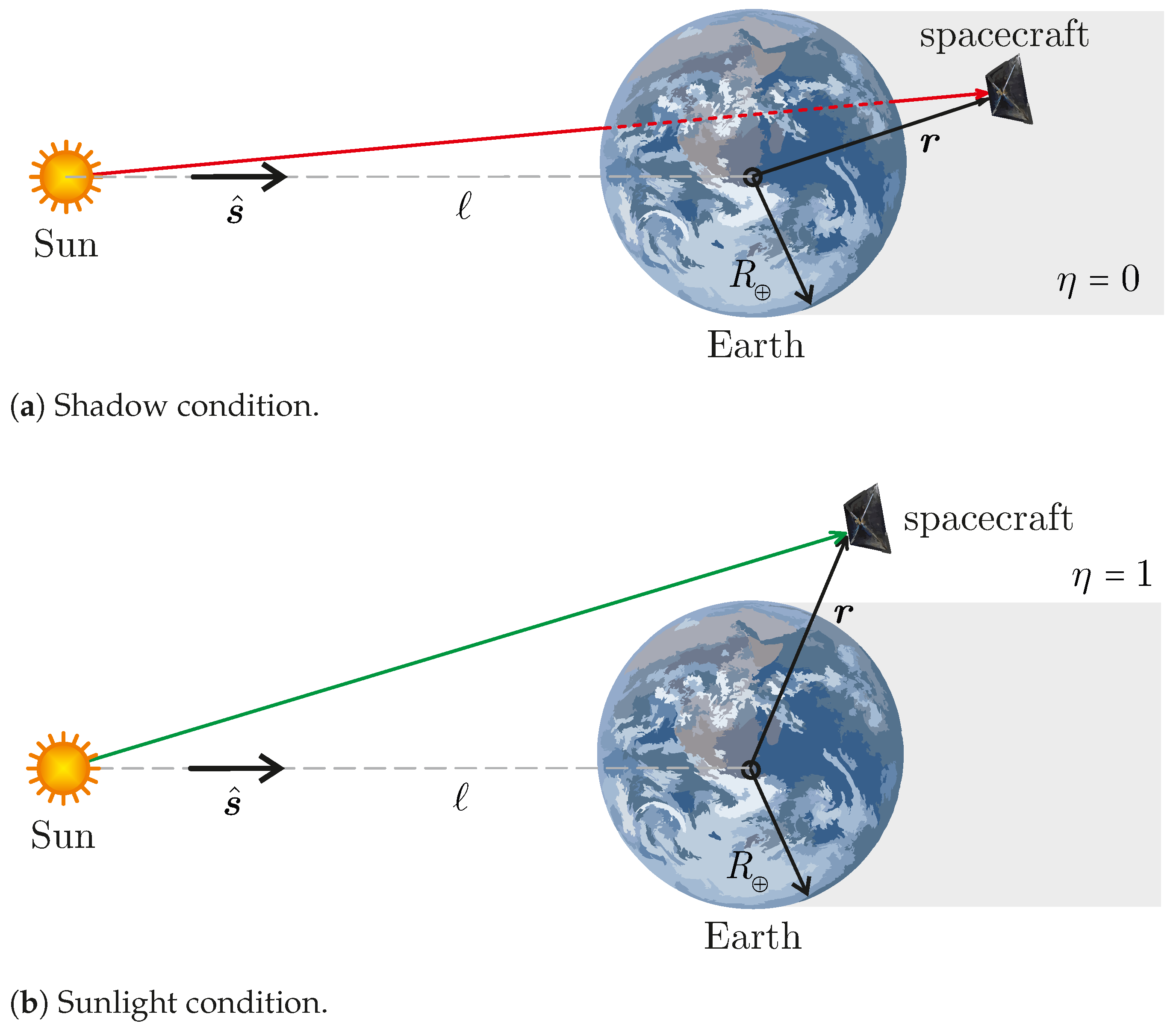
where P 4.5632 × 10 6 Pa is the solar radiation pressure at the Sun–spacecraft distance, which is assumed constant, and s ^ is the Sun–spacecraft unit vector. In addition, c r is the reflection coefficient of the drag sail, which is assumed to be small because drag sails, unlike solar sails, are not designed to take advantage of solar radiation pressure as a source of thrust. For this reason, drag sails are usually low reflective to reduce light pollution [64]. Accordingly, and in analogy with the drag sail models discussed in Ref. [65], a value of c r = 0.1 is assumed in this work. The parameter η { 0 , 1 } in Equation (14) is used to determine whether eclipses occur with a cylindrical shadow model, i.e., η = 1 if the Sun–spacecraft line does not intersect the Earth (modeled as a sphere of radius R ), and η = 0 otherwise. With reference to Figure 2, the value of η can be determined from the instantaneous Sun–Earth vector l s ^ (with l 1 au ) and the Earth–spacecraft vector r .
Finally, with reference to Equation (14), since the unit vector normal to the sail surface must point in the direction opposite to the Sun, n ^ SRP in Equation (14) must be chosen such that n ^ SRP · s ^ 0 . This consideration removes the ambiguity about the definition of n ^ that arose in Section 2.1, that is,
n ^ SRP = n ^ if n ^ · s ^ 0 n ^ if n ^ · s ^ < 0
where n ^ is a freely selected normal unit vector n ^ .

3. Spinning Drag Sail Dynamics

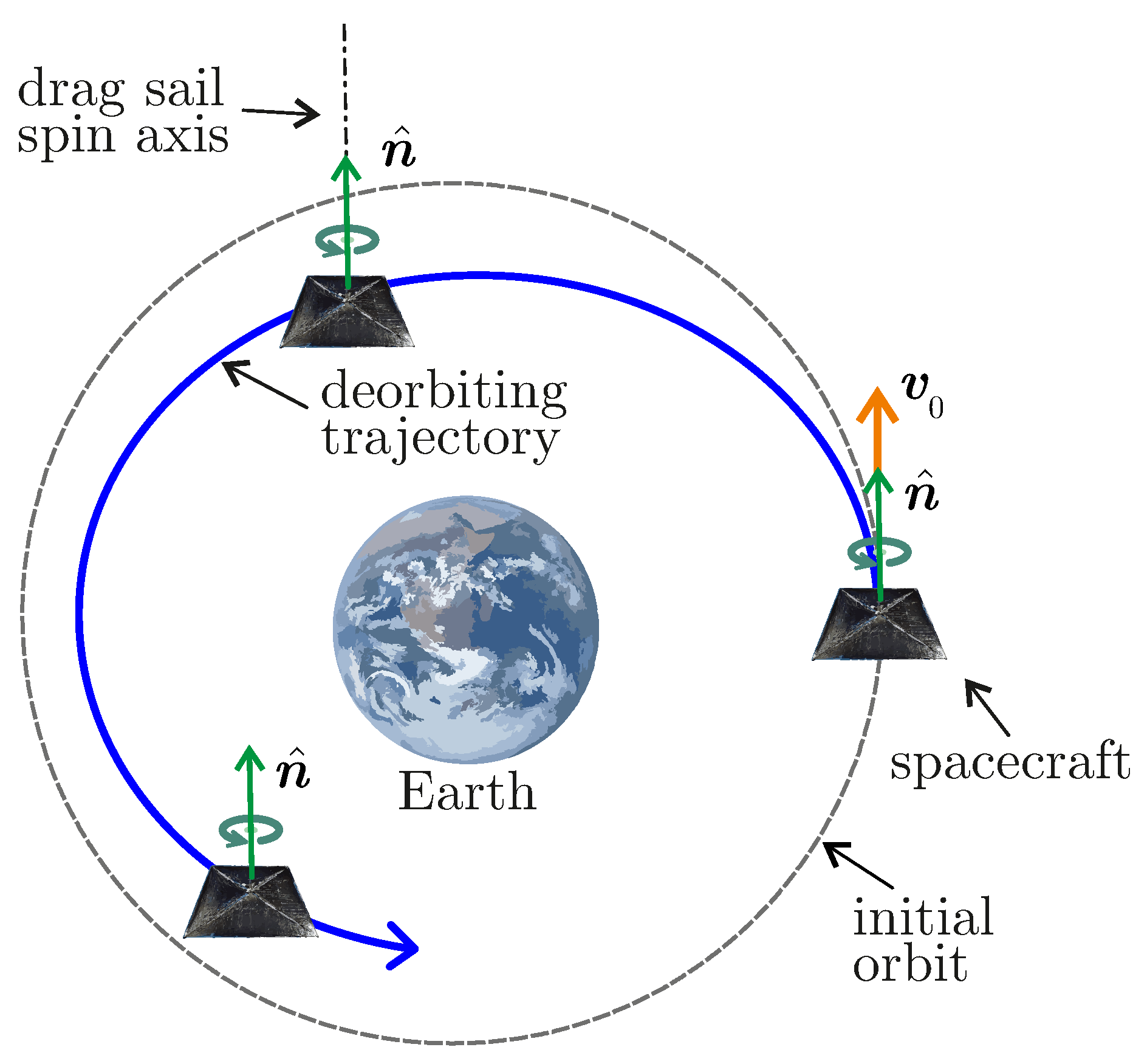
The decay trajectory of a drag sail spacecraft can be obtained by integrating Equation (3) with a numerical propagator. As discussed above, the perturbative acceleration of Equation (6) can be calculated as a function of the unit normal vector n ^ affecting aerodynamic perturbations, see Equations (10)–(12), and the acceleration due to solar radiation pressure, see Equations (14) and (15). In this analysis, the drag sail is assumed to be spinning. The deployment occurs at t 0 , when the deorbiting phase begins and the spacecraft’s angular velocity is perpendicular to the sail surface. The spacecraft rotation generates a centrifugal force that helps to properly deploy the sail, while its residual rotational velocity keeps the drag sail stretched without requiring large structural elements and provides gyroscopic stiffness. As a result, the spinning sail is assumed to keep its angular velocity vector normal to the sail surface (and so the unit vector n ^ ) inertially fixed. A conceptual sketch of the deorbiting scenario is shown in Figure 3.
The procedure for calculating the components of n ^ is as follows. The angular velocity of the spacecraft is aligned with the orbital velocity at t 0 and the deployment occurs when the flight path angle is zero. Without loss of generality, this amounts to assuming that n ^ ( t 0 ) v ^ ( t 0 ) , since n ^ can be selected in both directions perpendicular to the drag sail surface, see Section 2.1. Since n ^ is fixed inertially, it is convenient to write the components of n ^ ( t 0 ) in an inertial reference frame, as they will remain constant during the deorbiting phase, assuming that the sail spin rate provides a large gyroscopic stiffness. For this purpose, introduce an Earth-centered inertial (ECI) reference system T ECI , with origin G in the Earth’s center of mass, and unit vectors i ^ , j ^ , and k ^ . By definition, i ^ lies on the Earth’s equatorial plane and points towards the Aries point , k ^ is aligned with the Earth’s rotation axis in the direction of the North Pole, and j ^ belongs to the Equatorial plane and completes the right-handed triad; see Figure 1.
Since the perturbative acceleration is most simply written in the RTN frame, it is necessary to define the rotation matrix R between the ECI frame and the RTN frame, that is,
R = cos u sin u 0 sin u cos u 0 0 0 1 1 0 0 0 cos i sin i 0 sin i cos i cos Ω sin Ω 0 sin Ω cos Ω 0 0 0 1 = = cos Ω cos u sin Ω cos i sin u sin Ω cos u + cos Ω cos i sin u sin i sin u cos Ω sin u sin Ω cos i cos u cos Ω cos i cos u sin Ω sin u sin i cos u sin Ω sin i cos Ω sin i cos i
where u ω + ν . The same rotation matrix can be expressed in terms of MEOEs by substituting Equation (2) into Equation (16) and performing some algebraic manipulation. The result is
R = h 2   cos   L + 2 h k   sin   L k 2   cos   L +   cos   L 1 + k 2 + h 2 h 2   sin   L + 2 h k   cos   L + k 2   sin   L +   sin   L 1 + k 2 + h 2 2 h   sin   L 2 k   cos   L 1 + k 2 + h 2 h 2   sin   L + 2 h k   cos   L + k 2   sin   L   sin   L 1 + k 2 + h 2 h 2   cos   L 2 h k   sin   L + k 2   cos   L +   cos   L 1 + k 2 + h 2 2 h   cos   L + 2 k   sin   L 1 + k 2 + h 2 2 k 1 + k 2 + h 2 2 h 1 + k 2 + h 2 1 h 2 k 2 1 + k 2 + h 2
Accordingly, the components of n ^ in the ECI frame are given by
[ n ^ ] ECI [ n ^ 0 ] ECI = [ v ^ 0 ] ECI = R 0 T [ v ^ ( t 0 ) ] RTN
where R 0 is obtained by substituting the MEOEs of the starting orbit into Equation (17), and [ v ^ 0 ] RTN [ v 0 ] RTN / v 0 is calculated from MEOEs by means of Equation (9). Also, the (time-varying) components of n ^ in the RTN frame are given by
[ n ^ ] RTN = R [ n ^ 0 ] ECI = R R 0 T [ v ^ 0 ] RTN
where R is obtained at each time instant by substituting the instantaneous values of MEOEs into Equation (17).
The aerodynamic effects modeled by Equations (7) and (8) may be conveniently written directly in the RTN frame. To this end, the velocity vector [ v ] RTN is calculated by substituting the instantaneous values of MEOEs into Equation (9), and consequently [ v ^ ] RTN = [ v ] RTN / v is obtained. Then, the lift unit vector components in T RTN are calculated through Equation (10) as functions of [ v ^ ] RTN and [ n ^ ] RTN , the latter being given by Equation (19). Similarly, the values of drag ( C D ) and lift ( C L ) coefficients are obtained by Equations (11) and (12).
As for the atmospheric density, ρ could be obtained from MATLAB built-in function atmosnrlmsise00, which is based on the NRLMSISE-00 model [66]. It requires solar flux and geomagnetic data available online (see https://celestrak.org/spacedata, retrieved on 20 September 2023) and provides ρ as a function of the time instant t and of the spacecraft position vector r expressed in the ECI frame, that is,
[ r ] ECI = R T [ r ] RTN = R T p 1 + f   cos   L + g   sin   L 0 0
However, since the calculation of ρ through the NRLMSISE-00 model is computationally demanding, the number of required evaluations of the atmospheric density is reduced by applying an iterative procedure, analogous to what is done in Ref. [59]. More precisely, at a generic time instant t ˜ at which MEOEs are known, it is possible to calculate the osculating orbit period T ˜ = 2 π a ˜ 3 / μ , where the tilde symbol denotes quantities calculated at t = t ˜ . The orbital period T ˜ is divided into N equally spaced instants belonging to the set S defined as
S = t ˜ , t ˜ + T ˜ N 1 , t ˜ + 2 T ˜ N 1 , , t ˜ + ( N 2 ) T ˜ N 1 , t ˜ + T ˜
and the spacecraft is assumed to move on the osculating (Keplerian) orbit. Its angular position L ( t ) at each instant t S is obtained by solving a Kepler’s problem and, knowing L, it is possible to calculate the corresponding state vector x ( t ) and the spacecraft position vector in the ECI frame through Equation (20). The latter, together with the time instants t S , the solar flux and geomagnetic data, are given as inputs to the atmosnrlmsise00 function. The set of atmospheric density values
D = ρ ( t ˜ ) , ρ ( t ˜ + T ˜ / ( N 1 ) ) , , ρ ( t ˜ + T ˜ )
is therefore obtained. The set D divides the osculating orbit into N 1 time intervals in each of which the value of ρ is kept constant (equal to the average of the values calculated at the edges of each interval), then the iterative procedure is restarted with a new osculating orbit defined by the MEOEs obtained at t = t ˜ + T ˜ . In the simulations, a value N = 5 was chosen.
The components of the perturbative acceleration due to Earth’s oblateness a P J 2 are given in the RTN frame by Equation (13). When the instantaneous values of MEOEs are substituted into Equation (13), the components of a P J 2 are determined for each t t 0 .
Finally, the acceleration generated by the solar radiation pressure is obtained from Equation (14), which is conveniently written in the ECI frame. The Sun–spacecraft unit vector s ^ in the ECI frame is calculated as a function of the spacecraft instantaneous orbital parameters by applying the algorithm discussed in Ref. [67]. The normal unit vector n ^ SRP is selected by applying the procedure detailed in Equation (15) and recalling that the components of [ n ^ ] ECI , given by Equation (18), are constant. The eclipse factor η is determined from [ s ^ ] ECI and [ r ] ECI , the latter being calculated by substituting the MEOE into Equation (20). The perturbative term [ a P SRP ] ECI can then be calculated and its components in the RTN frame are given by [ a P SRP ] RTN = R [ a P SRP ] ECI , where R comes from Equation (17).

4. Performance Estimate of Spinning Drag Sail

The behavior of a spinning drag sail was simulated in some test scenarios with the aim of estimating the decay time of a spacecraft equipped with such a deorbiting device. For comparison purposes, the same deorbiting scenarios were also simulated for a three-axis stabilized drag sail [68] and for an uncontrolled drag sail. In all simulations, a total spacecraft mass m = 15 kg and a drag sail area of 5 m 2 were assumed. The chosen total mass is compatible with a 12U CubeSat, representative of small satellites whose numbers are increasing and which pose a greater deorbiting challenge than other common (and smaller) configurations, such as the 1U or 3U CubeSats. The value of the sail area is in accordance with drag sails currently being developed for small and medium-sized spacecraft [64]. The characteristics of the satellite used in the test case scenarios are summarized in Table 1.
The dynamics of a three-axis stabilized drag sail is obtained by integrating Equation (3) and evaluating the perturbative accelerations through Equations (7), (8), (13) and (14). However, in this case, it is assumed that the drag sail constantly exposes its entire surface to the flow of atmospheric particles by means of a perfectly functioning three-axis stabilization system or a suitable passively stabilizing drag sail design [44,46,47,48]. This amounts to assuming that n ^ v ^ at each time t t 0 during the deorbiting trajectory. Such a drag sail configuration provides the shortest decay times but requires a fully functional attitude control system.
In the uncontrolled case, instead, the drag sail is again deployed by the spacecraft at t 0 , but it is assumed that the spacecraft does not have a functioning attitude control system, so it is unable to control its attitude. Therefore, it is subject to environmental torques and undergoes a tumbling motion during orbital decay. In this case, the dynamics of the spacecraft’s center of mass is still obtained by integrating Equation (3), but the computation of the components of n ^ requires some further clarification. In fact, n ^ is first given in a body-fixed reference frame. Then, it is transformed into T RTN by applying a rotation matrix whose components depend on the Euler angles between the body-fixed frame and the RTN frame. These angles are obtained by modeling the spacecraft attitude by means of an attitude quaternion [69,70,71] and calculating the angular velocity of the spacecraft with respect to T RTN by means of the Euler equations. Since these equations need the spacecraft’s moments of inertia, the latter were calculated by accounting for the contributions of the spacecraft body, modeled as a uniform parallelepiped of 14.5 kg with dimensions 0.4 m × 0.3 m × 0.1 m , and a square, flat, uniform sail membrane with a mass of 0.5 kg . The corresponding principal moments of inertia are given in Table 1. Finally, the external torques acting on the spacecraft were calculated in analogy with Refs. [46,47] by taking into account three contributions, that is, the torque generated by aerodynamic effects a P D + a P L , the torque due to solar radiation pressure, and the gravity gradient torque. For simulation purposes, the center of pressure of the aerodynamic torques was assumed to coincide with that of the solar radiation pressure torques, which are located on the sail membrane and are displaced by 0.1 m relative to the center of the sail in each of the two spatial coordinates.
To make a comparison between different drag sail configurations, several initial orbits were considered, chosen from the most populated orbital ranges, see Ref. [10]. All of the selected orbits are circular, with altitude h 0 = 600 km , that is, the initial semimajor axis is a 0 = 6978 km . This choice is motivated by a trade-off between the importance of an effective deorbiting strategy (which increases with altitude due to the reduced atmospheric density) and computational effort, which is reduced for shorter flight times. The four selected orbits are (i) a dawn-dusk Sun-synchronous orbit (SSO), (ii) a noon-midnight SSO, (iii) a medium-inclination orbit with i 0 = 53 deg and Ω 0 = 30 deg , and (iv) an equatorial orbit. These choices are based on an ESA report [10]. In particular, Sun-synchronous orbits (i) and (ii) are highly populated by spacecraft performing remote sensing observation, whereas the 53 deg -inclination case (iii) has been chosen because of the large density of satellite constellations [9], thus increasing the collision probability for nearby spacecraft. The equatorial orbit (iv) has been included to account for a low-inclination scenario. For each selected orbit, the deployment is assumed to take place when L 0 = Ω 0 , without loss of generality. For each initial orbit, two simulations were performed, selecting t 0 either on 1 January 2014 or on 1 January 2019. The first case is near a solar maximum (reported in the last months of 2014) and is representative of the most favorable situation to achieve a fast decay. Starting in January 2019, on the other hand, is equivalent to performing much of the deorbiting within a solar activity minimum, thus achieving slow orbital decay.
Numerical simulations were performed with commercial MATLAB software (version R2023a) on a desktop computer with an i7-11700F-2.50 GHz processor. Considering the three-axis stabilized and spinning sail configurations, typical simulation times are in the order of minutes when starting at a solar maximum, and in the order of tens of minutes if t 0 is at a solar minimum. The uncontrolled satellite case, on the other hand, involves a significant computational cost, such that each numerical simulation requires a computational time in the order of several hours starting from a solar maximum and as much as 15–20 h starting from a solar minimum. Such a significant difference in computational cost for the uncontrolled scenario is mainly due to the need to simulate the dynamics of spacecraft attitude, which has much faster dynamics than the evolution of MEOEs and thus requires short time steps to be properly evaluated.
The results of the numerical simulations are given in Table 2 and Table 3 for a deorbiting starting at a solar maximum and at a solar minimum, respectively. The two tables show the decay times from the initial altitude of 600 km to a final altitude set equal to 200 km , a value chosen assuming that reentry ends when the spacecraft reaches the dense layers of the atmosphere. In addition, the last column of the tables shows the time savings obtained with a three-axis stabilized sail and a spinning sail compared to the uncontrolled case. Table 2 shows that for deorbiting from a high solar activity, the time savings obtained with a spinning sail are significant, although lower than those given by a three-axis stabilized sail, and are particularly remarkable for Sun-synchronous orbits, which are very common for LEO satellites. The only notable exception is the case of medium-inclination orbit, for which no time savings are achieved with a spinning sail. One possible explanation for this counterintuitive result is provided by experimental data obtained from measurements made by LightSail-2, a 3U CubeSat that deorbited from a medium-inclination orbit, according to which the aerodynamic torque can help the spacecraft stabilize in a favorable attitude in the final stages of its decay trajectory [72].
Similar considerations can be extended to the results shown in Table 3, which refer to deorbiting scenarios starting from a solar minimum. In this case, the time savings are generally less substantial than in the solar maximum cases shown in Table 2. However, the decay time reductions achieved with a spinning sail are still relevant, particularly if tighter time limits are to be adopted to mitigate the orbital debris problem in the near future. Again, the only exception is the medium-inclination case, for which no time savings are achieved with a spinning sail.
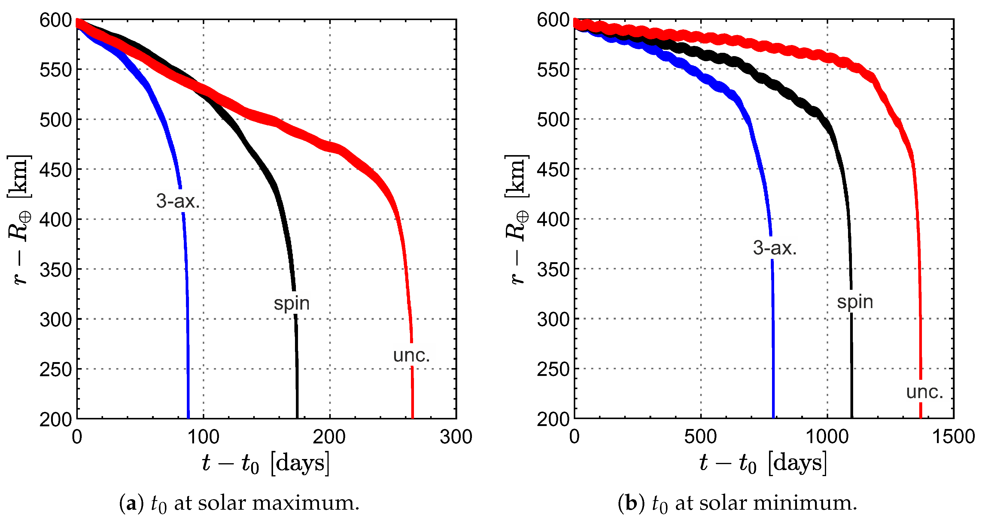
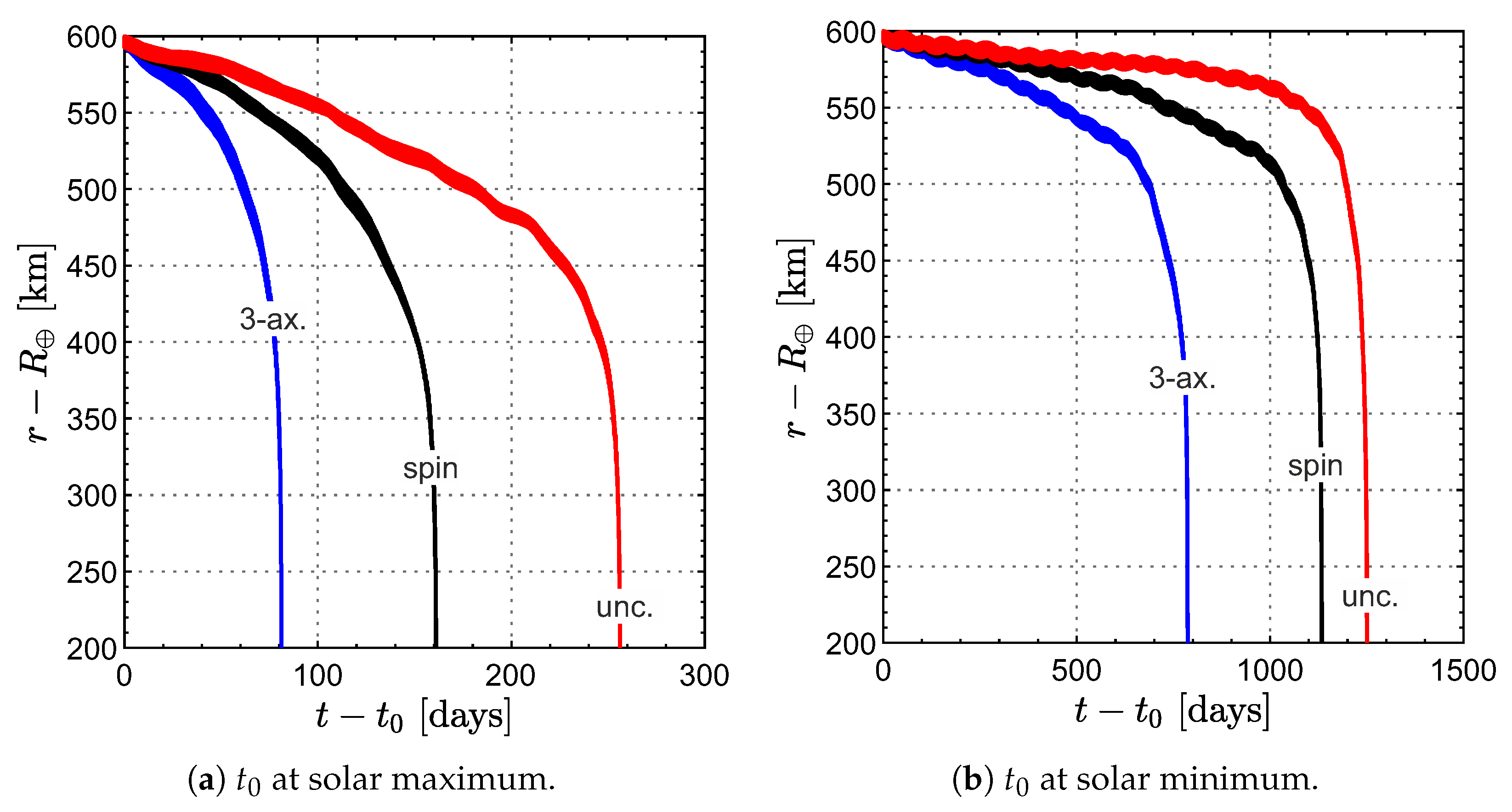
An even more complete picture of the performance of a spinning drag sail is obtained from the graphs showing the temporal changes in altitude for the three different types of drag sails considered. An example of such graphs is shown in Figure 4 and Figure 5, which illustrate the deorbiting profiles for a dawn-dusk and a noon-midnight SSO, respectively. In both cases, it is evident that the rapidity of altitude variation in the case of uncontrolled drag sail is significantly lower than in the case of spinning sail, especially under conditions of high solar activity. Figure 6 shows the same results as in Figure 5 for a spinning drag sail during the first day of decay, highlighting the short-term oscillations in spacecraft altitude due to the action of perturbative accelerations, which are associated with the spacecraft motion along the osculating orbit. This highly perturbed environment is the reason for the high computational costs of numerical simulations.

5. Conclusions

In this study, a spin-stabilized drag sail was proposed as a tool to perform spacecraft deorbiting from a low Earth orbit. The proposed configuration represents a sufficiently simple deorbiting device since it does not require an active attitude control system for proper operation and is well suited for satellites with a medium-to-large area-to-mass ratio. The deorbiting scenarios have been analyzed by making the assumption that the axis of rotation of the drag sail remains inertially fixed, due to gyroscopic stiffness, throughout the deorbiting trajectory. The spacecraft dynamics was simulated using the modified equinoctial elements because they ensure the absence of singularities in time responses. The model used takes into account the most relevant sources of perturbation for a spacecraft in low Earth orbit, that is, aerodynamic forces (drag and lift), Earth oblateness effect, and solar radiation pressure. The decay times obtained with a spinning drag sail were estimated assuming different initial orbits and were compared with those obtained for a three-axis stabilized sail and an uncontrolled sail. The results show that the performance of a spinning drag sail, while worse than that of a three-axis stabilized sail, yields significant time savings compared with the case of uncontrolled drag sail, especially when starting from a Sun-synchronous orbit and using an area-to-mass ratio compatible with that of a small or medium-sized satellite.

Author Contributions

Conceptualization, L.N.; methodology, L.N. and G.M.; software, L.N.; writing—original draft preparation, L.N. and G.M.; writing—review and editing, G.M. All authors have read and agreed to the published version of the manuscript.

Funding

This research was funded by the University of Pisa, Progetti Ricerca di Ateneo, grant number PRA_2022_1.

Institutional Review Board Statement

Not applicable.

Informed Consent Statement

Not applicable.

Data Availability Statement

Data is contained within the article.

Conflicts of Interest

The authors declare no conflicts of interest.

Abbreviations

The following abbreviations are used in this manuscript:
ECIEarth-centered inertial
LEOlow Earth orbit
MEOEmodified equinoctial orbital element
RTNradial-tangential-normal
SRPsolar radiation pressure
SSOSun-synchronous orbit
Nomenclature
A state dynamical matrix, see Equation (4)
Adrag sail area [m 2 ]
aosculating orbit semimajor axis [km]
a P perturbative acceleration vector [km/s 2 ]
b auxiliary vector, see Equation (5)
C D drag coefficient, see Equation (11)
C L lift coefficient, see Equation (12)
c r reflection coefficient
D set of atmospheric density values, see Equation (22)
eosculating orbit eccentricity
GEarth’s center of mass
J 2 Earth’s second zonal harmonics
iosculating orbit inclination [deg]
{ i ^ , j ^ , k ^ } ECI frame unit vectors
{ i ^ R , i ^ T , i ^ N } RTN frame unit vectors
L ^ lift unit vector, see Equation (10)
l Sun–Earth distance [au]
mspacecraft total mass [kg]
Nnumber of density evaluations
n ^ unit vector normal to the sail
n ^ SRP normal unit vector associated with SRP perturbation, see Equation (15)
Ospacecraft center of mass
P solar radiation pressure at 1 au from the Sun [Pa]
{ p , f , g , h , k , L } modified equinoctial orbital elements of the osculating orbit
R rotational matrix from ECI frame to RTN frame
R Earth’s equatorial radius [km]
r Earth–spacecraft vector [km]
rEarth–spacecraft distance [km]
S set of time instants, see Equation (21)
s ^ Sun–spacecraft unit vector
T ECI Earth-centered inertial frame
T RTN radial-tangential-normal frame
Tosculating orbit period [hours]
ttime instant [days]
uosculating orbit argument of latitude [deg]
V R ratio of particle thermal velocity to orbital velocity
v spacecraft orbital velocity vector [km/s]
x state vector
η eclipse parameter
μ Earth’s gravitational parameter [km 3 /s 2 ]
ν spacecraft true anomaly on the osculating orbit [deg]
ρ atmospheric density, [kg/m 3 ]
σ N normal momentum accommodation coefficient
σ T tangential momentum accommodation coefficient
Ω osculating orbit right ascension of the ascending node [deg]
ω osculating orbit argument of pericenter [deg]
Subscripts
0 initial value
Ddrag perturbation
ECIrelative to the ECI frame
J 2 Earth’s oblateness perturbation
Llift perturbation
RTNrelative to the RTN frame
SRPsolar radiation pressure perturbation
Superscripts
· derivative with respect to time
unit vector
generic time instant
Ttranspose matrix

References

  1. Sweeting, M.N.; Foquet, M. Earth observation using low cost micro/minisatellites. Acta Astronaut. 1996, 39, 823–826. [Google Scholar] [CrossRef]
  2. Wekerle, T.; Filho, J.B.P.; da Costa, L.E.V.L.; Trabasso, L.G. Status and trends of smallsats and their launch vehicles—An up-to-date review. J. Aerosp. Technol. Manag. 2017, 9, 269–286. [Google Scholar] [CrossRef]
  3. Niccolai, L.; Bassetto, M.; Quarta, A.A.; Mengali, G. A review of Smart Dust architecture, dynamics, and mission applications. Prog. Aerosp. Sci. 2019, 106, 1–14. [Google Scholar] [CrossRef]
  4. Twiggs, R.J. Space system developments at Stanford University: From launch experience of microsatellites to the proposed future use of picosatellites. Proc. SPIE 2000, 4136, 79–86. [Google Scholar] [CrossRef]
  5. Kestilä, A.; Tikka, T.; Peitso, P.; Rantanen, J.; Näsilä, A.; Nordling, K.; Saari, H.; Vainio, R.; Janhunen, P.; Praks, J.; et al. Aalto-1 nanosatellite-technical description and mission objectives. Geosci. Instrum. Methods Data Syst. 2013, 2, 121–130. [Google Scholar] [CrossRef]
  6. Umansky-Castro, J.S.; Mesquita, J.M.B.; Kumar, A.; Anderson, M.; Tung, T.Y.; Wen, J.J.; Adams, V.H.; Peck, M.A.; Filo, A.; Carabellese, D.; et al. Design of the Alpha CubeSat: Technology demonstration of a chipsat-equipped retroreflective light sail. In Proceedings of the AIAA SciTech Forum, Virtual Event, 11–15 & 19–21 January 2021. [Google Scholar] [CrossRef]
  7. Dalbins, J.; Allaje, K.; Ehrpais, H.; Iakubivskyi, I.; Ilbis, E.; Janhunen, P.; Kivastik, J.; Merisalu, M.; Noorma, M.; Pajusalu, M.; et al. Interplanetary student nanospacecraft: Development of the LEOdemonstrator ESTCube-2. Aerospace 2023, 10, 503. [Google Scholar] [CrossRef]
  8. Murtaza, A.; Pirzada, S.J.H.; Xu, T.; Jianwei, L. Orbital debris threat for space sustainability and way forward (review article). IEEE Access 2020, 8, 6100–61019. [Google Scholar] [CrossRef]
  9. Ren, S.; Yang, X.; Wang, R.; Liu, S.; Sun, X. The interaction between the LEO satellite constellation and the space debris environment. Appl. Sci. 2021, 11, 9490. [Google Scholar] [CrossRef]
  10. ESA’s Annual Space Debris Environment Report; Techreport; ESA: Wan Chai, Hong Kong, 2022.
  11. Kessler, D.J.; Cour-Palais, B.G. Collision frequency of artificial satellites: The creation of a debris belt. J. Geophys. Res. 1978, 83, 2637–2646. [Google Scholar] [CrossRef]
  12. Kessler, D.J. Collisional cascading: The limits of population growth in low earth orbit. Adv. Space Res. 1991, 11, 63–66. [Google Scholar] [CrossRef]
  13. Liou, J.C.; Johnson, N.L. Risks in space from orbiting debris. Science 2006, 311, 340–341. [Google Scholar] [CrossRef]
  14. Kessler, D.J.; Johnson, N.L.; Liou, J.C.; Matney, M. The Kessler Syndrome: Implications to future space operations. Adv. Astronaut. Sci. 2010, 137, 47–61. [Google Scholar]
  15. Schäfer, F.; Lambert, M.; Christiansen, E.; Kibe, S.; Stokes, H.; Reimerdes, H.G.; Meshcheryakov, S.A.; Angrilli, F.; Zengyao, H. The Inter-Agency Space Debris Coordination Committee (IADC) protection manual. In Proceedings of the 4th European Conference on Space Debris, Darmstadt, Germany, 18–20 April 2005. [Google Scholar]
  16. Yakovlev, M. The “IADC space debris mitigation guidelines” and support document. In Proceedings of the 4th European Conference on Space Debris, Darmstadt, Germany, 18–20 April 2005. [Google Scholar]
  17. Liou, J.C.; Johnson, N.L. Instability of the present LEO satellite populations. Adv. Space Res. 2008, 41, 1046–1053. [Google Scholar] [CrossRef]
  18. Liu, M.; Wang, H.; Yi, H.; Xue, Y.; Wen, D.; Wang, F.; Shen, Y.; Pan, Y. Space debris detection and positioning technology based on multiple star trackers. Appl. Sci. 2022, 12, 3593. [Google Scholar] [CrossRef]
  19. Shan, M.; Guo, J.; Gill, E. Review and comparison of active space debris capturing and removal methods. Prog. Aerosp. Sci. 2016, 80, 18–32. [Google Scholar] [CrossRef]
  20. Mark, C.P.; Kamath, S. Review of active space debris removal methods. Space Policy 2019, 47, 194–206. [Google Scholar] [CrossRef]
  21. Hubert Dekuskem, M.; Christidi-Loumpasefski, O.O.; Yalçin, B.C.; Li, X.; Olivares-Mendez, M.; Martinez, C. Hybrid-compliant system for soft capture of uncooperative space debris. Appl. Sci. 2023, 13, 7968. [Google Scholar] [CrossRef]
  22. Tang, C.; Deng, Y.; Bai, Z.; Wei, C.; Zhao, Y. Dynamics analysis of space netted pocket system capturing non-cooperative target. Appl. Sci. 2023, 13, 10377. [Google Scholar] [CrossRef]
  23. Sanchez-Arriaga, G.; Sanmartin, J.R.; Lorenzini, E.C. Comparison of technologies for deorbiting spacecraft from low-Earth-orbit at end of mission. Acta Astronaut. 2017, 138, 536–542. [Google Scholar] [CrossRef]
  24. Colombo, C.; Rossi, A.; Dalla Vedova, F.; Francesconi, A.; Bombardelli, C.; Trisolini, M.; Gonzalo, J.L.; Di Lizia, P.; Giacomuzzo, C.; Khan, S.B.; et al. Effects of passive de-orbiting through drag and solar sails and electrodynamic tethers on the space debris environment. In Proceedings of the 69th International Astronautical Congress (IAC), Bremen, Germany, 1–5 October 2018. [Google Scholar]
  25. Zhong, R.; Zhu, Z.H. Dynamics of nanosatellite deorbit by bare electrodynamic tether in Low Earth Orbit. J. Spacecr. Rocket. 2013, 50, 691–700. [Google Scholar] [CrossRef]
  26. Janhunen, P. Electrostatic plasma brake for deorbiting a satellite. J. Propuls. Power 2010, 26, 370–372. [Google Scholar] [CrossRef]
  27. Orsini, L.; Niccolai, L.; Mengali, G.; Quarta, A.A. Plasma brake model for preliminary mission analysis. Acta Astronaut. 2017, 144, 297–304. [Google Scholar] [CrossRef]
  28. Iakubivskyi, I.; Janhunen, P.; Praks, J.; Allik, V.; Bussov, K.; Clayhills, B.; Dalbins, J.; Eenmäe, T.; Ehrpais, H.; Envall, J.; et al. Coulomb drag propulsion experiments of ESTCube-2 and FORESAIL-1. Acta Astronaut. 2020, 177, 771–783. [Google Scholar] [CrossRef]
  29. Palmroth, M.; Praks, J.; Vainio, R.; Janhunen, P.; Kilpua, E.K.J.; Afanasiev, A.; Ala-Lahti, M.; Alho, A.; Asikainen, T.; Asvestari, E.; et al. FORESAIL-1 CubeSat mission to measure radiation belt losses and demonstrate deorbiting. J. Geophys. Res. Space Phys. 2019, 124, 5783–5799. [Google Scholar] [CrossRef]
  30. Fernandez, J.M.; Visagie, L.; Schenk, M.; Stohlman, O.R.; Aglietti, G.S.; Lappas, V.J.; Erb, S. Design and development of a gossamer sail system for deorbiting in low Earth orbit. Acta Astronaut. 2014, 103, 204–225. [Google Scholar] [CrossRef]
  31. Visagie, L.; Lappas, V.J.; Erb, S. Drag sails for space debris mitigation. Acta Astronaut. 2015, 109, 65–75. [Google Scholar] [CrossRef]
  32. Serfontein, Z.; Kingston, J.; Hobbs, S.; Holbrough, I.E.; Beck, J.C. Drag augmentation systems for space debris mitigation. Acta Astronaut. 2021, 188, 278–288. [Google Scholar] [CrossRef]
  33. Spencer, D.A.; Johnson, L.; Long, A.C. Solar sailing technology challenges. Aerosp. Sci. Technol. 2019, 93, 105276. [Google Scholar] [CrossRef]
  34. Quarta, A.A.; Mengali, G. Solar sail orbit raising with electro-optically controlled diffractive film. Appl. Sci. 2023, 13, 7078. [Google Scholar] [CrossRef]
  35. Colombo, C.; Rossi, A.; Francesconi, A.; Dalla Vedova, F.; Gonzalo, J.L.; Braun, V.; Bastida Virgili, B.; Krag, H. Long-term simulations to assess the effects of drag and solar sails on the space debris environment. In Proceedings of the 70th International Astronautical Congress (IAC), Washington, DC, USA, 21–25 October 2019. [Google Scholar]
  36. Kerr, E.; Macdonald, M. Limits of drag augmentation at spacecraft end-of-mission and a mitigation strategy. Astrodynamics 2021, 5, 109–120. [Google Scholar] [CrossRef]
  37. Johnson, L.; Whorton, M.; Heaton, A.; Pinson, R.; Laue, G.; Adams, C. NanoSail-D: A solar sail demonstration mission. Acta Astronaut. 2011, 68, 571–575. [Google Scholar] [CrossRef]
  38. Svitek, T.; Friedman, L.; Nye, W.; Biddy, C.; Nehrenz, M. Voyage continues-LightSail-1 mission by the planetary society. In Proceedings of the 61st International Astronautical Congress, Prague, Czech Republic, 27 September–1 October 2010. [Google Scholar]
  39. Ridenoure, R.W.; Spencer, D.A.; Stetson, D.A.; Betts, B.; Munakata, R.; Wong, S.D.; Diaz, A.; Plante, B.A.; Foley, J.D.; Ballardo, J.M. Status of the dual CubeSat LightSail program. In Proceedings of the AIAA SPACE Conference and Exposition, Pasadena, CA, USA, 31 August–2 September 2015. [Google Scholar] [CrossRef]
  40. Nutter, A.; Bauda, C.; Culeux, J.; Straubel, M.; Zander, M.E.; Hillebrandt, M. Objectives, design and initial test results of the upcoming GAMA-Beta solar sail in-orbit demonstration. In Proceedings of the 6th International Symposium on Space Sailing (ISSS), New York, NY, USA, 5–9 June 2023. [Google Scholar]
  41. Kuwahara, T.; Yoshida, K.; Sakamoto, Y.; Tomioka, Y.; Fukuda, K.; Fukuyama, M.; Tanabe, T.; Shibuya, Y. Qualification results of a sail deployment mechanism for active prevention and reduction of space debries. In Proceedings of the 63rd International Astronautical Congress (IAC), Naples, Italy, 30 September–5 October 2012. [Google Scholar]
  42. Underwood, C.; Viquerat, A.; Schenk, M.; Taylor, B.; Massimiani, C.; Duke, R.; Stewart, B.; Fellowes, S.; Bridges, C.; Aglietti, G.S.; et al. InflateSail de-orbit flight demonstration results and follow-on drag-sail applications. Acta Astronaut. 2019, 162, 344–358. [Google Scholar] [CrossRef]
  43. Bonin, G.; Hiemstra, J.; Sears, T.; Zee, R.E. The CanX-7 drag sail demonstration mission: Enabling environmental stewardship for nano- and microsatellites. In Proceedings of the 27th Annual AIAA/USU Conference on Small Satellites, Logan, UT, USA, 4 August 2013. [Google Scholar]
  44. Nock, K.T.; Gates, K.L.; Aaron, K.M.; McRonald, A.D. Gossamer orbit lowering device (GOLD) for safe and efficient de-orbit. In Proceedings of the AIAA/ASS Astrodynamics Specialist Conference, Toronto, ON, Canada, 2–5 August 2010. [Google Scholar] [CrossRef]
  45. Black, A.; Spencer, D.A. DragSail systems for satellite deorbit and targeted reentry. J. Space Saf. Eng. 2020, 7, 397–403. [Google Scholar] [CrossRef]
  46. Miguel, N.; Colombo, C. Deorbiting spacecraft with passively stabilised attitude using a simplified quasi-rhombic-pyramid sail. Adv. Space Res. 2021, 67, 2561–2576. [Google Scholar] [CrossRef]
  47. Zhang, J.R.; Zhang, R.N.; Yang, K.Y. Attitude stability analysis and configuration design of pyramid drag sail for deorbit missions. J. Aerosp. Eng. 2022, 35, 04022084. [Google Scholar] [CrossRef]
  48. Zhang, R.N.; Yang, R.Y.; Zhang, J.R.; Bi, S.F. Dynamics analysis and optimal strategy of pyramid deorbit sail. In Proceedings of the 73rd International Astronautical Congress (IAC), Paris, France, 18–22 September 2022. [Google Scholar]
  49. MacNeal, R.H. The Heliogyro—An Interplanetary Flying Machine; Techreport CR 84469; NASA: Washington, DC, USA, 1967.
  50. Burton, R.; Coverstone, V.; Hargens-Rysanek, J.; Ertmer, K.; Botter, T.; Benavides, G.; Woo, B.; Carroll, D.; Gierow, P.; Farmer, G.; et al. UltraSail-Ultra-lightweight solar sail concept. In Proceedings of the 41st AIAA/ASME/SAE/ASEE Joint Propulsion Conference, Tucson, AZ, USA, 10–13 July 2005. [Google Scholar]
  51. Hargens-Rysanek, J. The Dynamics and Control of the UltraSail System. Ph.D. Thesis, University of Illinois, Champaign, IL, USA, 2006. [Google Scholar]
  52. Hargens-Rysanek, J.; Coverstone, V.L.; Burton, R.L. Orbital precession via cyclic pitch for the UltraSail system. In Proceedings of the 17th AAS/AIAA Space Flight Mechanics Meeting, Sedona, AZ, USA, 28 January–1 February 2007. [Google Scholar]
  53. Sawada, H.; Mori, O.; Okuizumi, N.; Shirasawa, Y.; Miyazaki, Y.; Natori, M.; Matunaga, S.; Furuya, H.; Sakamoto, H. Mission report on the solar power sail deployment demonstration of IKAROS. In Proceedings of the 52nd AIAA/ASME/ASCE/AHS/ASC Structures, Structural Dynamics and Materials Conference, Denver, CO, USA, 4–7 April 2011. [Google Scholar] [CrossRef]
  54. Tsuda, Y.; Mori, O.; Funase, R.; Sawada, H.; Yamamoto, T.; Saiki, T.; Endo, T.; Yonekura, K.; Hoshino, H.; Kawaguchi, J. Achievement of IKAROS-Japanese deep space solar sail demonstration mission. Acta Astronaut. 2013, 82, 183–188. [Google Scholar] [CrossRef]
  55. Sakamoto, H.; Shirasawa, Y.; Haraguchi, D.; Sawada, H.; Mori, O. A spin-up control scheme for contingency deployment of the sailcraft IKAROS. In Proceedings of the 52nd AIAA/ASME/ASCE/AHS/ASC Structures, Structural Dynamics and Materials Conference, Denver, CO, USA, 4–7 April 2011. [Google Scholar] [CrossRef]
  56. Walker, M.J.H.; Ireland, B.; Owens, J. A set of modified equinoctial orbit elements. Celest. Mech. 1985, 36, 409–419. [Google Scholar] [CrossRef]
  57. Lücking, C.; Colombo, C.; McInnes, C.R. A passive satellite deorbiting strategy for medium Earth orbit using solar radiation pressure and the J2 effect. Acta Astronaut. 2012, 77, 197–206. [Google Scholar] [CrossRef]
  58. Lücking, C.; Colombo, C.; McInnes, C.R. Solar radiation pressure-augmented deorbiting: Passive end-of-life disposal from high-altitude orbits. J. Spacecr. Rocket. 2013, 50, 1256–1267. [Google Scholar] [CrossRef]
  59. Carzana, L.; Visser, P.; Heiligers, J. Locally optimal control laws for Earth-bound solar sailing with atmospheric drag. Aerosp. Sci. Technol. 2022, 127, 107666. [Google Scholar] [CrossRef]
  60. Storch, J.A. Aerodynamic Disturbances on Spacecraft in Free-Molecular Flow; Technical Report ADA410696; The Aerospace Corporation: El Segundo, CA, USA, 2002. [Google Scholar]
  61. Mengali, G.; Quarta, A.A. Near-optimal solar-sail orbit-raising from low Earth orbit. J. Spacecr. Rocket. 2005, 42, 954–958. [Google Scholar] [CrossRef]
  62. Stolbunov, V.; Ceriotti, M.; Colombo, C.; McInnes, C.R. Optimal law for inclination change in an atmosphere through solar sailing. J. Guid. Control. Dyn. 2013, 36, 1310–1323. [Google Scholar] [CrossRef]
  63. Dachwald, B. Minimum transfer times for nonperfectly reflecting solar sailcraft. J. Spacecr. Rocket. 2004, 41, 693–695. [Google Scholar] [CrossRef]
  64. Stelzl, D.; Seefeldt, P.; Killian, M.; Hofmann, L.; Puttich, G.; Lopez-Corralez, X.; Garcia Mora, C.; Pimpi, J.; Schuhbaur, M.; Stolz, O.; et al. The ADEO space sail products. In Proceedings of the 6th International Symposium on Space Sailing (ISSS), New York, NY, USA, 5–9 June 2023. [Google Scholar]
  65. Colombo, C.; Rossi, A.; Dalla Vedova, F.; Brun, V.; Bastida Virgili, B.; Krag, H. Drag and solar sail deorbiting: Re-entry time versus cumulative collision probability. In Proceedings of the 68th International Astronautical Congress (IAC), Adelaide, Australia, 25–29 September 2017. [Google Scholar]
  66. Picone, J.M.; Hedin, A.E.; Drob, D.P.; Aikin, A.C. NRLMSISE-00 empirical model of the atmosphere: Statistical comparisons and scientific issues. J. Geophys. Res. Space Phys. 2002, 107, 1468. [Google Scholar] [CrossRef]
  67. Vallado, D.A. Fundamentals of Astrodynamics and Applications; Chapter 3.5; McGraw-Hill: New York, NY, USA, 1997; pp. 181–184. [Google Scholar]
  68. Mahdi, M.C. Attitude Stabilization for CubeSat: Concepts and Technology; Chapter 2; Cambridge Scholars Publishing: Newcastle upon Tyne, UK, 2018; pp. 37–50. [Google Scholar]
  69. Wertz, J.R. (Ed.) Spacecraft Attitude Determination and Control; Chapter Appendix D; Kluwer Academic Publishers: Alphen aan den Rijn, The Netherlands, 1978; pp. 758–759. [Google Scholar]
  70. Wie, B.; Barba, P.M. Quaternion feedback for spacecraft large angle maneuvers. J. Guid. Control. Dyn. 1985, 8, 360–365. [Google Scholar] [CrossRef]
  71. Markley, F.L.; Crassidis, J.L. Fundamentals of Spacecraft Attitude Determination and Control; Chapter 2.9.3; Springer: Berlin/Heidelberg, Germany, 2014; pp. 45–48. [Google Scholar] [CrossRef]
  72. Mansell, J.R.; Bellardo, J.M.; Betts, B.; Plante, B.; Spencer, D.A. LightSail 2 solar sail control and orbit evolution. Aerospace 2023, 10, 579. [Google Scholar] [CrossRef]
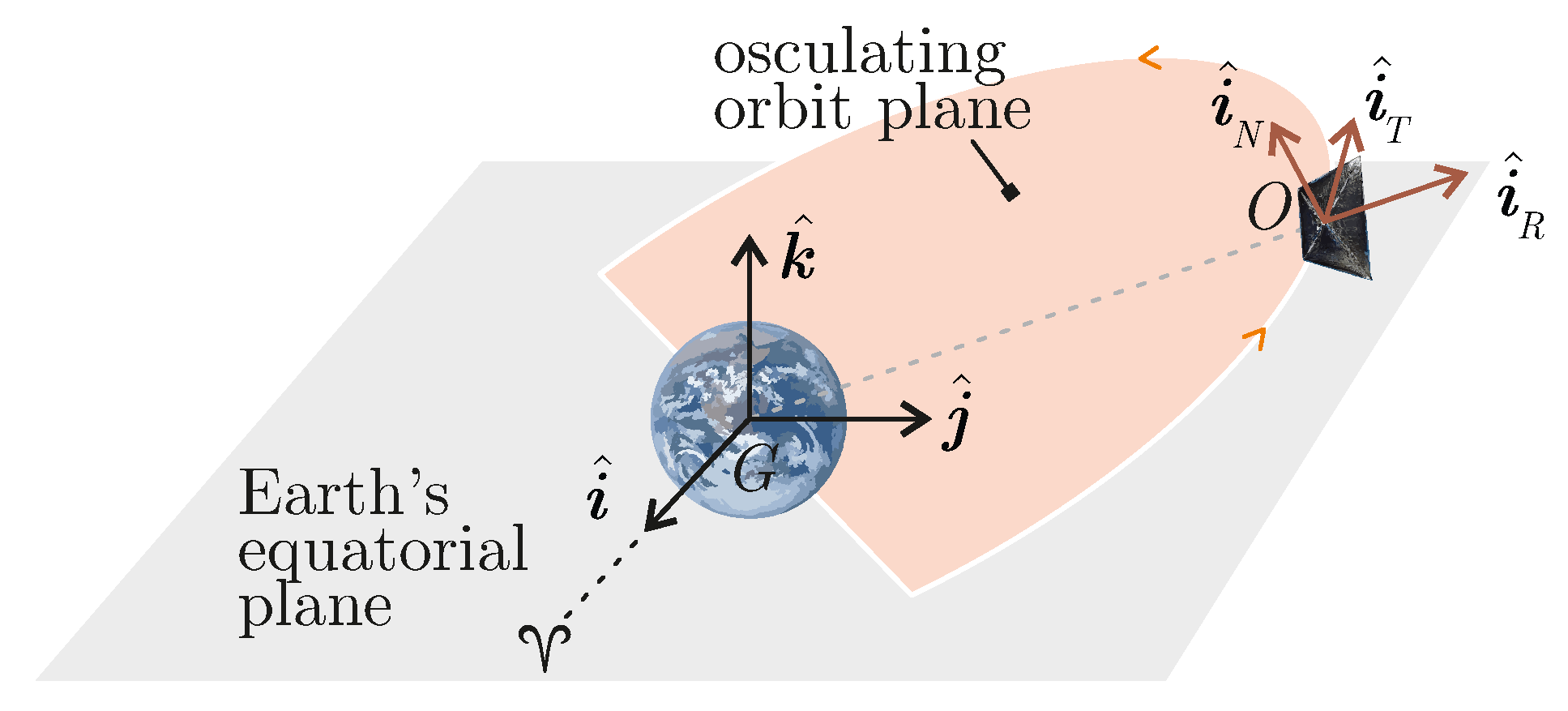
Figure 1. Sketch of RTN and ECI reference frames.
Applsci 14 00612 g001
Figure 2. Conceptual sketch of cylindrical-shadow eclipse model (not to scale).
Applsci 14 00612 g002
Figure 3. Sketch of the spinning drag sail-based deorbiting.
Applsci 14 00612 g003
Figure 4. Decay trajectory from a dawn-dusk SSO for a satellite with parameters given in Table 1 with different drag sail configurations (blue = three-axis stabilized sail; black = spin-stabilized sail; red = uncontrolled sail).
Applsci 14 00612 g004
Figure 5. Decay trajectory from a noon-midnight SSO for a satellite with parameters given in Table 1 with different drag sail configurations (blue = three-axis stabilized sail; black = spin-stabilized sail; red = uncontrolled sail).
Applsci 14 00612 g005
Figure 6. First day of the decay trajectory from a noon-midnight SSO for a satellite with parameters given in Table 1 equipped with a spinning drag sail.
Applsci 14 00612 g006
Table 1. Spacecraft design parameters used in the simulations. Drag sail characteristics are taken from the ADEO-N model, see Ref. [64].
ParameterValueUnit
Total spacecraft mass m15 kg
Spacecraft body mass 14.5 kg
Drag sail mass 0.5 kg
Spacecraft body dimensions 0.4 × 0.3 × 0.1 m 3
Drag sail area A5 m 2
Moments of inertia { 0.5375 , 0.5298 , 0.4331 } kg m 2
Table 2. Deorbiting performance for different drag sail configurations and initial orbits under high-solar-activity conditions.
OrbitSail ConfigurationDecay Time [Years]Time Saving [%]
dawn-dusk SSOthree-axis0.24166.8
spinning0.47734.4
uncontrolled0.727
noon-midnight SSOthree-axis0.22268.3
spinning0.44137.1
uncontrolled0.702
medium inclinationthree-axis0.23167.8
spinning0.777−8.5
uncontrolled0.717
equatorialthree-axis0.20973.0
spinning0.40747.5
uncontrolled0.775
Table 3. Deorbiting performance for different drag sail configurations and initial orbits under low-solar-activity conditions.
OrbitSail ConfigurationDecay Time [Years]Time Saving [%]
dawn-dusk SSOthree-axis2.15442.6
spinning3.10317.2
uncontrolled3.750
noon-midnight SSOthree-axis2.07139.5
spinning2.98412.8
uncontrolled3.424
medium inclinationthree-axis2.18736.4
spinning3.4340.1
uncontrolled3.437
equatorialthree-axis2.07938.8
spinning3.0938.9
uncontrolled3.396
Disclaimer/Publisher’s Note: The statements, opinions and data contained in all publications are solely those of the individual author(s) and contributor(s) and not of MDPI and/or the editor(s). MDPI and/or the editor(s) disclaim responsibility for any injury to people or property resulting from any ideas, methods, instructions or products referred to in the content.