Abstract
This paper presents a hierarchical baseline stereo-matching framework for depth estimation using a novelly developed light field camera. The imaging process of a micro-lens array-based light field camera is derived. A macro-pixel map is constructed by treating each micro-lens as one macro-pixel in the light field’s raw image. For each macro-pixel, a feature vector is represented by leveraging texture and gradient cues over the surrounding ring of neighboring macro-pixels. Next, the micro-lenses containing edges are detected on the macro-pixel map. Hierarchical baseline stereo-matching is performed by macro-pixel-wise coarse matching and pixel-wise fine matching, effectively eliminating matching ambiguities. Finally, a post-processing step is applied to improve accuracy. The lab-designed light field camera’s imaging performance is evaluated in terms of accuracy and processing speed by capturing real-world scenes under studio lighting conditions. And an experiment using rendered synthetic samples is conducted for quantitative evaluation, showing that depth maps with local details can be accurately recovered.
1. Introduction
Recovering depth information for real-world scenes and objects is desirable and crucial in widespread applications, such as the LiDAR (light detection and ranging) system [1,2], digital/meta-human creation [3], and so on. In the past two decades, advancements in the field of computer vision have opened up new opportunities for achieving precise depth maps, which can be categorized as active and passive imaging methods. Active 3D imaging devices, such as the TOF (time of flight) camera, a structured-light camera, and a laser scanner, employ controlled lighting or electromagnetic radiation to measure depth values within a limited and fixed range of depth [4]. However, the obtained depth maps are noise-sensitive and lack local details, especially for small objects. On the other hand, passive 3D imaging systems like MVS (multi-view stereo) and PS (photometric stereo), exploit visual information (for example, texture, shading, defocus) to estimate depth values from a series of 2D images. These images are taken from different viewpoints with wide baselines under a controlled lighting environment. To date, most imaging methods face challenges when dealing with textureless, transparent, or reflective surfaces; moreover, the calibration of cameras and lighting conditions is essential.
As emerging passive 3D imaging devices, light field cameras are capable of capturing dense multi-view 2D images in a single snapshot and operate under conditions prohibitive to other RGB-D cameras, e.g., in bright sunlight or underwater [5]. Consumer light field cameras (e.g., Lytro [6], Raytrix [7]) are produced by inserting a micro-lens array between the main lens and the photosensor. This special in-camera aperture division imaging structure measures the intensities and directions of rays simultaneously. Moreover, the additional ray information significantly enhances post-processing capabilities, including depth estimation and digital refocusing [4].
Light field imaging has some distinct advantages: (a) for micro-lens array-based light field cameras, the FoV (field of view) and depth range can be dynamically adjusted by manipulating the focal length of the main lens, well-suited for capturing small-sized objects at a distance; (b) LF imaging can be easily integrated with other imaging systems [8].
Classical stereo-matching methods are only valid on viewpoints with wide baselines (such as a baseline of 32, 64, or 128 pixels), which are simple in theory and execute rapidly. Due to the large baseline and sparse angular sampling, stereo-matching encounters challenges leading to depth ambiguities and matching inconsistencies in occlusions, repeated textures, or textureless regions, as well as extreme lighting conditions. Existing methods often enforce a consistency constraint and utilize neighboring depth distributions to fill in gaps [9].
However, the sub-aperture images decoded from light field imaging have an extremely narrow baseline, typically ranging from 3 to 5 pixels for Lytro Illum. This results in inconsistent and sparse matching, accompanied by blurriness and ambiguities. Therefore, directly estimating depth information with a light field camera is challenging due to the inherent narrow baseline and the trade-off between spatial and angular resolution.
In the past two decades, many algorithms have been proposed to improve the accuracy of depth estimation from light field imaging. These include machine learning methods [10,11,12,13,14] and deep learning methods [15,16,17,18,19]. Considering the input data structure, depth estimation methods can be categorized into three types: EPIs (epipolar plane images), SAIs (sub-aperture images), and focal stacks. The main workflow involves feature extraction, cost construction, cost aggregation, and disparity regression. Both Jeon et al. [12] and Zhang et al. [10] exploited the phase shift theorem in the Fourier domain to represent sub-pixel displacement. Wang et al. [11] proposed an occlusion-aware framework using a modified angular photo-consistency for occlusion prediction, and they fused depth, correspondence, and refocus cues for robust depth estimation. Zhang et al. [13] proposed a spinning parallelogram operator based on EPIs, using a confidence metric to integrate information from the LF structure, thus reducing occlusions and ambiguities. Tsai et al. [15] proposed a view selection module that generated an attention map, indicating the importance of each view for accurate depth estimation. Chen et al. [16] developed an attention-based multi-level fusion network, designing intra-branch and inter-branch strategies for hierarchically fusing effective features from different views. Wang et al. [17] constructed an occlusion-aware cost volume via dilated convolutions and dynamically modulated pixels from different views. They also developed a disentangling mechanism, which incorporates prior knowledge of the LF structure for depth estimation, as well as for spatial and angular super-resolution, using macro-pixel representation as input [18]. Chen et al. [19] proposed a post-refinement network for bad-pixel correction by taking an initial disparity map as input, introducing a phase-shift-based warping and data augmentation strategy.
Most existing algorithms focus on how to explore the depth cues within the spatial–angular information of 4D light fields. However, the extremely narrow baseline and the trade-off between spatial–angular resolution make depth estimation from LF imaging a challenging task, often resulting in poor robustness and high computational costs.
In this paper, we focus on applying a hierarchical baseline stereo-matching framework to recover depth maps with local geometric details from a pair of light field stereo images. The light field raw images are captured by a newly designed camera, and this work aims to test the imaging performance of this camera. Without a large dataset and ground-truth depth maps, the proposed framework relies on a traditional stereo-matching strategy for 4D light field data, supplemented by a post-processing step. Furthermore, we evaluate both the accuracy and the processing speed for real-world scenes and rendered synthetic samples.
The contributions of this paper are as follows:
- The imaging process of a micro-lens array-based light field camera is derived. Firstly, a macro-pixel map is built by setting each micro-lens as one macro-pixel in the light field raw image. Then, a feature vector for each macro-pixel is represented by exploiting texture and gradient cues over the surrounding k-ring neighboring macro-pixels.
- To develop the imaging and reconstruction platform based on a lab-designed light field camera, macro-pixel-wise coarse matching and pixel-wise fine matching are performed as hierarchical baseline stereo-matching. This approach can effectively handle complex locally textured objects and eliminate matching ambiguities. Additionally, a post-processing step with a pre-trained network is applied to improve accuracy.
- The imaging performance of the light field camera is tested in terms of accuracy and processing speed by capturing real-world scenes under a studio lighting environment. Furthermore, a quantitative evaluation is carried out on rendered synthetic samples. The experimental results demonstrate that the developed platform can recover depth maps with almost real-time online processing.
2. Light Field Camera and Imaging Modeling
In this section, the lab-designed light field camera is introduced (Figure 1). Further, the imaging theory is derived by modeling the imaging process of the micro-lens array light field camera based on the ray tracing theory. Table 1 shows the imaging parameters of Raytrix R29, Lytro Illum, and lab-designed cameras. Meanwhile, two imaging structures, Plenoptic and , are shown in Figure 1d,e.
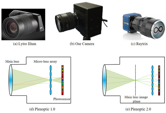
Figure 1.
(a) Lytro Illum camera. (b) Lab-designed camera. (c) Raytrix camera. (d) The Plenoptic structure of the light field camera [6]. The micro-lens array (MLA) is on the focal plane of the main lens. (e) The Plenoptic structure of the light field camera [7], which is called the “Focused Plenoptic camera”.

Table 1.
Comparison between different light field cameras. “✔” represents support. “-” represents not support. SDK denotes the software development kit.
2.1. Light Field Camera
Adelson et al. [20] first defined the concept of the “Plenoptic Camera” in 1992. Then, Ren Ng et al. [6] designed the first hand-held light field camera with a Plenoptic structure in 2005. As shown in Figure 1, the consumer light field cameras in the past decades include the Lytro Illum in the Plenoptic structure and the Raytrix in the Plenoptic structure. Moreover, in 2019, VOMMA (Shanghai) [21] produced consumer light field acquisition chips for 3D measurement and detection applications. By setting the relative positions of the main lens, micro-lens array, and photosensor, the imaging structure corresponds to Plenoptic and , and the captured light fields exhibit significant variations in spatial and angular resolution, requiring specialized decoding and post-processing methods.
As shown in Table 1, the lab-designed camera follows the Plenoptic structure, similar to the Lytro Illum, but with more advanced features. In contrast to the Raytrix camera, although the camera lens is replaceable, challenges arise from the secondary development of the SDK (Software Development Kit) due to the third-party hardware and its limited openness. Additionally, adjusting imaging parameters according to varying lighting environments has proven to be difficult. The lab-designed light field camera can capture both images (.raw) and videos (.vraw) to generate 5D data (where t is the time dimension). Moreover, for ease of use, we have made significant improvements in both the hardware and software. Before capturing objects, a series of white images are captured for each lighting environment. Then the entire processing framework, which includes decoding, calibration, devignetting, enhancement, depth estimation, and 3D display, takes less than one second, thanks to acceleration with GPU computing.
2.2. Imaging Modeling
As shown in Figure 2a, each light ray is illustrated by its interactions with two parallel planes—the plane describes the ray’s angular direction and the plane describes the ray’s spatial position. Therefore, for the 4D light field function, , denotes the index of different angular viewpoints, and denotes the spatial coordinates on each sub-aperture view [4].
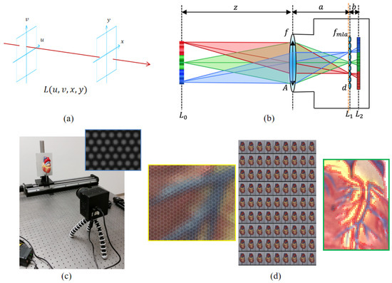
Figure 2.
(a) Two-plane representation of 4D light fields . (b) The imaging system for a micro-lens array (MLA) light field camera. is the focal length of the micro-lens, and f is the focal length of main lens. d is the macro-pixel size. A is the aperture size of the main lens. z is the object/scene distance. a is the distance between the main lens and micro-lens array. b is the distance between the micro-lens array and photosensor. (c) The capturing system based on the lab-designed camera. The top right is a zoom-in of the captured light field raw image (.raw). (d) Left: zoom-in processed light field color raw image. It is easy to see the micro-lens array structure. Middle: decoded sub-aperture images with a narrow baseline. Right: the edge macro-pixel detection results.
As shown in Figure 2b, light field imaging can be viewed as capturing rays within a scene through a grid of lenses from different viewpoints. For the Plenoptic 1.0 light field camera (such as the Lytro Illum and the lab-designed camera), the distance between the micro-lens array and the photosensor equals the focal length of the micro-lens, i.e., . The range of each macro-pixel in the x dimension is d, and the FoV (field of view) is . Furthermore, the aperture size of the main lens is A, and the distance between the main lens and the micro-lens array is a. To maximize the utilization of sensor pixels, the F-number of both the main lens and the micro-lens should be equal, [22]; that is
If the angular resolution is , the DoF (depth of focus) of the light field camera is over the DSLR (digital singular lens reflex) camera, but spatial resolution is only . This is the trade-off between spatial and angular resolution for light field imaging.
3. The Proposed Approach
In this section, the proposed framework is described step by step. A light field stereo image pair (.raw) denotes the input data. Each light field raw image can be decoded into 4D light fields , with the resolution of sub-aperture images being , where 3 represents the RGB channels.
3.1. Macro-Pixel Map Construction
Firstly, the decoding and calibration methods proposed by Dansereau et al. [5] are used to generate the sub-aperture images and . Then, several white images are captured to calculate the average white image. Light field raw images are then obtained by demosaicking the Bayer-pattern raw images. Finally, the micro-lens grid spacing is transformed and aligned to the integer pixel grid spacing by locating the centers of each micro-lens.
Because the micro-lens grid is hexagonally packed, decoding leads to noisy pixels with vignetting and bias near the edges of micro-lenses [5]. Hence, we ignore the edge pixels in each micro-lens to construct the macro-pixel map , where is the coordinate index of each micro-lens.
For the lab-developed light field camera, the resolution of the micro-lens raw image is , and the decoded light fields are . One macro-pixel is then constructed by extracting the central pixels from each micro-lens.
3.2. Feature Description and Edge Macro-Pixel Detection
The specific local features for each macro-pixel are described by exploiting texture and gradient cues over k-ring neighboring macro-pixels. Based on the hexagonally packed micro-lens grid, the feature vector is made of 7 micro-lenses in neighboring macro-pixels, as shown in Figure 3c.
where denotes the color of each pixel in . denotes both the gradients of pixels in , as well as the micro-lens-wise gradients from three directions (,, and ).
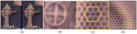
Figure 3.
(a) The epipolar geometry of the stereo vision light field system. (b) The light field raw image. (c) The neighboring macro-pixels. (d) The Sobel operator.
Edge-aware filters, such as the bilateral filter, are typically effective for edge-preserving smoothing and local matching cost aggregation [23]. Micro-lenses containing edges of target objects are considered as edge macro-pixels in . Edge macro-pixel detection is performed using a rule similar to the Sobel operator. The mean intensity vector is computed over two kinds of neighboring macro-pixels centered on . Then, a Sobel convolution is executed on . The result of the edge macro-pixel detection is shown in Figure 2d. In the following steps, edge macro-pixels tend to match with high confidence.
3.3. Hierarchical Baseline Stereo-Matching
In this section, the hierarchical baseline stereo-matching process is introduced in detail. First, the background is masked out from light field raw images. Then, a macro-pixel map pyramid is constructed through Gaussian convolution by downsampling. It is important to note that the Gaussian convolution is applied over neighboring macro-pixels centered on each macro-pixel. In the experiment, the proposed pyramid has four layers, with the top layer consisting of macro-pixels. The resulting disparity values of the low-scale layer are taken as prior knowledge input for the next layer, which can narrow the search range and improve matching accuracy while being less time-consuming.
In each layer of the pyramid, three steps are performed: coarse matching, constraint enhancement, and fine matching.
3.3.1. Coarse Matching
Coarse matching is executed macro-pixel-wise, rather than pixel-wise, along the corresponding epipolar line between the light field raw image pair. The matching cost indicates how well a macro-pixel in corresponds to the macro-pixel in . Zero-mean normalized cross-correlation (ZNCC) has been verified as robust to illumination changes and is widely used in window-based local stereo-matching methods.
where and are feature vectors of macro-pixels and ; n is the pixel number; is the average value of each feature vector.
Then, we filter the cost volume using the guided filter [24]. It should be noted that, although Gaussian convolution is performed during the pyramid’s construction, the macro-pixel map cannot be used as color guidance due to aliasing effects. Therefore, we generate the center sub-aperture image by taking the central angular pixels from macro-pixels and perform guided filtering with this center sub-aperture image. Based on the filtered cost volume, the disparity for each macro-pixel is determined with the highest NCC score using the WTA (winner-take-all) strategy.
3.3.2. Constraint Enhancement
NCC matching cost is only locally invariant to linear radiometric changes. If the target object has a textured Lambertian reflectance surface, dense coarse disparity results are obtained with high NCC scores. However, in the presence of occlusions, shadows, and specular reflectance, some macro-pixels may be mismatched with low NCC scores. To remove ambiguities and outliers, three constraints are enhanced: uniqueness, smoothness, and ordering.
The uniqueness constraint ensures that if in matches in , then must also match . If , is occluded. A left–right consistency check is executed to detect occluded as well as mismatched macro-pixels, tolerating up to one macro-pixel.
The smoothness constraint is based on the consistent property in a locally surrounding window, except in-depth discontinuity regions. Disparity differences between and neighboring macro-pixels are calculated as . If more than half of these differences are larger than the threshold , is mismatched to an invalid disparity. Edge macro-pixels, generally having high matching confidence, are not subject to enhancement by the smoothness constraint.
The ordering constraint means that the disparity for cannot exceed the disparity of its right neighbor, , by more than macro-pixels. Finally, invalid macro-pixels must be assigned new proper disparities that comply with all constraints. To perform edge-preserving filtering, a weighted median filter [25] is applied, taking into account the edge macro-pixels.
3.3.3. Fine Matching
Fine matching plays an important role in recovering high-quality local details. Similar to subpixel interpolation in traditional stereo vision, fine matching is applied through sub-macro-pixel interpolation. Since coarse matching is conducted on a macro-pixel-wise basis, sub-macro-pixel interpolation computes pixel-wise matching. If a macro-pixel matches with the disparity , the feature vector for pixel-wise matching is recalculated by fusing and as
where and are feature vectors of and ; , ; if , , so do .
Thus, matching is performed between V and using ZNCC, and the disparity is chosen by WTA. Finally, a pre-trained post-refinement network for bad-pixel correction [19] is directly applied without training. The hierarchical structure has been proven to be effective in eliminating matching ambiguities on textureless and specular reflection surfaces.
4. Experimental Results
In this section, comprehensive experiments are presented and analyzed both quantitatively and qualitatively to evaluate the effectiveness and accuracy. The data include both rendered synthetic samples and real-world scenes captured by a lab-developed light field camera under a controlled studio lighting environment.
4.1. Capturing System
As shown in Figure 2c, a capturing system using the lab-designed light field camera is constructed. The camera’s position and imaging parameters are fixed, while the object moves horizontally on a slide rail. Most objects in the experiments are approximately small in size, around 10 cm × 20 cm, and captured at a near distance. However, measuring highly detailed depth values poses a challenge for some consumer 3D imaging devices at the same distance. A TOF camera with a valid depth range of 1.0 m–5.0 m, only can capture the object’s silhouette but without any detailed geometric depth information.
The lab-developed light field camera presents a compelling solution for capturing fine details of small-sized objects by offering precise control over the FoV (field of view) and depth range. Meanwhile, the lighting condition is continuously controlled based on the output depth values.
The target object is segmented from the background in light field raw images. In the feature vector construction step, the k-ring neighboring macro-pixels are chosen to be from the top to the bottom layer of the pyramid. And in the smoothness constraint enhancement, we set the neighboring macro-pixels to , and . Both the matching cost computation and constraint enhancement are linear operations, contributing to reduced processing time.
4.2. Results on Rendered Synthetic Samples
Three textured synthetic samples are rendered using the Blender add-on setup from Honauer et al. [26] as in Liu et al. [14]. These samples are designed by rendering 3D models of photorealistic scenes containing various properties. The evaluation metrics include RMSE (root mean square error), Bad Pixel () and Bad Pixel () metrics. The focus distance for the ‘Room’ samples is 1.0 m, and for the ‘Basket’ sample, it is 1.5 m. The focal length is set to 50 mm. All synthetic samples feature complex shapes and textures.
With the ground truth depth map and imaging parameters known, the light field disparity and depth values can be inter-transformed for evaluation based on the formulas in [26]. It can be seen from the statistical results in Table 2 and Figure 4 that the proposed method is more accurate, and the post-refinement is effective. For ‘Basket’, depth ambiguities are observed over the floor and background, but the depth accuracy for thin shapes is good.
Table 2.
Evaluations on the synthetic samples rendered by Blender. The evaluation metrics are RMSE, Bad Pixel , and Bad Pixel . Our_0 represents the results before post-refinement. The bold results are the best, and the underlined results are the second best.
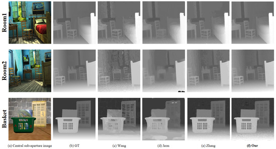
Figure 4.
Experimental results for synthetic samples rendered by Blender. Top: Room1. Middle: Room2. Bottom: Basket. (a) Central sub-aperture image. (b) The ground truth disparity map. (c) Wang et al. [11]. (d) Jeon et al. [12]. (e) Zhang et al. [13]. (f) Our results.
4.3. Results on Real-World Scenes
In order to test the effectiveness of the proposed method, qualitative evaluations are performed on real-world scenes using the capturing system with a lab-designed camera (Figure 2c).
Figure 5 shows depth estimation results for objects in a pseudo-color manner. The depth values are not in the same range due to different label numbers and settings, with a simple rescale operation applied for [11,12,13]. Although it is hard to correctly transform the estimated values into a unified range without exact imaging parameters, the depth details can still be easily identified from Figure 5 by the pseudo-color representation.
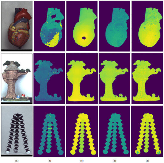
Figure 5.
Experimental results for real-world samples. (a) Central sub-aperture image. (b) Wang et al. [11]. (c) Jeon et al. [12]. (d) Zhang et al. [13]. (e) Our results.
As we know, most filters are used to generate smooth and continuous depth maps based on surrounding neighboring pixels. Depth discontinuities refer to abrupt or sudden changes corresponding to boundary edges between surfaces. In [12], over-filtering leads to depth discontinuities being blurred, creating ambiguities for thin shapes.
Another difficulty lies in densely changing textured surfaces. It is challenging to discern whether pixels with repeated textures are on the same depth plane or different depth planes. And ambiguities often occur over shadows and large specular reflection surfaces.
By exploiting light field imaging, which captures more rays and generates high-dimensional data, the proposed hierarchical baseline stereo-matching method aims to recover accurate geometric details and handle illumination changes rapidly (in less than one second).
Figure 6 shows depth estimation results for the hand gesture with point cloud outputs. Objects with strongly textured Lambertian surfaces under uniform lighting are the best cases for the proposed framework. Because of the angular viewpoint difference in the light field raw images, we can recover accurate local geometric details for a small object at a distance.
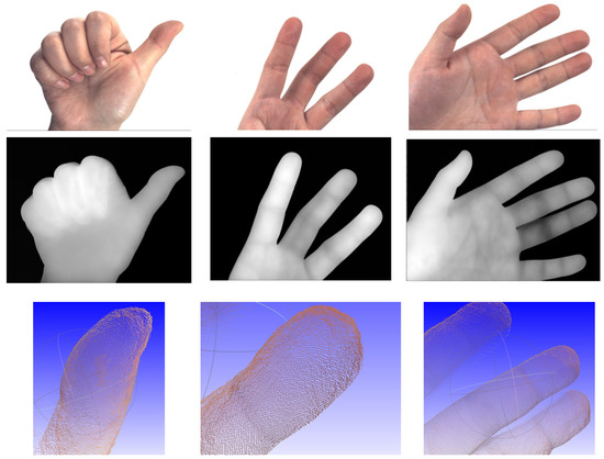
Figure 6.
Experimental results for the hand. Top: center sub-aperture image. Middle: depth map. Bottom: zoom-in point cloud outputs.
5. Conclusions
In this paper, in order to develop an online-processing light field platform based on the lab-designed camera, we present a depth estimation framework through hierarchical baseline stereo-matching from a pair of light field raw images. Due to limitations in generalizability, applying deep learning models without specific training is particularly challenging for real-world scenes. By fusing macro-pixel-wise coarse stereo-matching and pixel-wise fine stereo-matching, along with a post-refinement pre-trained network, the proposed method has been evaluated as significantly more effective, showing a range of accuracy improvements in handling real-world small objects at a distance.
In the future, a lot of work is needed to produce an exceptionally accurate, robust, and efficient depth estimation framework for objects with challenging textures under various lighting conditions using light field cameras. Also, a large dataset will be constructed to train deep learning models.
Author Contributions
Methodology, F.L.; validation, G.H.; writing—original draft preparation, F.L.; software, G.H. All authors have read and agreed to the published version of the manuscript.
Funding
This research received no external funding.
Institutional Review Board Statement
Not applicable.
Informed Consent Statement
Not applicable.
Data Availability Statement
The data presented in this study are available upon request from the first or corresponding author. The data are not publicly available due to privacy.
Conflicts of Interest
The authors declare no conflicts of interest.
References
- Gharineiat, Z.; Tarsha Kurdi, F.; Campbell, G. Review of Automatic Processing of Topography and Surface Feature Identification LiDAR Data Using Machine Learning Techniques. Remote Sens. 2022, 14, 4685. [Google Scholar] [CrossRef]
- Solares-Canal, A.; Alonso, L.; Picos, J.; Armesto, J. Automatic tree detection and attribute characterization using portable terrestrial lidar. Trees 2023, 37, 963–979. [Google Scholar] [CrossRef]
- Tian, Y.; Zhang, H.; Liu, Y.; Wang, L. Recovering 3D Human Mesh from Monocular Images: A Survey. IEEE Trans. Pattern Anal. Mach. Intell. 2023, 45, 15406–15425. [Google Scholar] [CrossRef] [PubMed]
- Liu, F.; Hou, G.; Sun, Z.; Tan, T. High quality depth map estimation of object surface from light-field images. Neurocomputing 2017, 252, 3–16. [Google Scholar] [CrossRef]
- Dansereau, D.G.; Pizarro, O.; Williams, S.B. Decoding, Calibration and Rectification for Lenselet-based Plenoptic Cameras. In Proceedings of the IEEE Conference on Computer Vision and Pattern Recognition (CVPR), Portland, OR, USA, 23–28 June 2013; pp. 1027–1034. [Google Scholar]
- Ren, N.; Marc, L.; Mathieu, B.; Gene, D.; Mark, H.; Hanrahan, P. Light Field Photography with a Hand-Held Plenoptic Camera. Doctoral Dissertation, Stanford University, Stanford, CA, USA, 2005; Volume 2. pp. 1–11.
- Georgiev, T.; Lumsdaine, A. Focused plenoptic camera and rendering. J. Electron. Imaging 2010, 19, 021106. [Google Scholar]
- Zhang, Y.; Li, Z.; Yang, W.; Yu, P.; Lin, H.; Yu, J. The light field 3D scanner. In Proceedings of the International Conference on Computational Photography (ICCP), Stanford, CA, USA, 12–14 May 2017; pp. 1–9. [Google Scholar]
- Hosni, A.; Rhemann, C.; Bleyer, M.; Rother, C.; Gelautz, M. Fast Cost-Volume Filtering for Visual Correspondence and Beyond. IEEE Trans. Pattern Anal. Mach. Intell. (TPAMI) 2013, 35, 504–511. [Google Scholar] [CrossRef] [PubMed]
- Zhang, Z.; Liu, Y.; Dai, Q. Light Field from Micro-baseline Image Pair. In Proceedings of the IEEE Conference on Computer Vision and Pattern Recognition (CVPR), Boston, MA, USA, 7–12 June 2015; pp. 3800–3809. [Google Scholar]
- Wang, T.C.; Efros, A.; Ramamoorthi, R. Occlusion-aware depth estimation using light-field cameras. In Proceedings of the International Conference on Computer Vision (ICCV), Santiago, Chile, 7–13 December 2015; pp. 3487–3495. [Google Scholar]
- Jeon, H.G.; Park, J.; Choe, G.; Park, J.; Bok, Y.; Tai, Y.W.; Kweon, I.S. Accurate depth map estimation from a lenslet light field camera. In Proceedings of the IEEE Conference on Computer Vision and Pattern Recognition (CVPR), Boston, MA, USA, 7–12 June 2015; pp. 1547–1555. [Google Scholar]
- Zhang, S.; Sheng, H.; Li, C.; Zhang, J.; Xiong, Z. Robust depth estimation for light field via spinning parallelogram operator. Comput. Vis. Image Underst. (CVIU) 2016, 145, 148–159. [Google Scholar] [CrossRef]
- Liu, F.; Zhou, S.; Wang, Y.; Hou, G.; Sun, Z.; Tan, T. Binocular light-field: Imaging theory and occlusion-robust depth perception application. IEEE Trans. Image Process. 2020, 29, 1628–1640. [Google Scholar] [CrossRef] [PubMed]
- Tsai, Y.J.; Liu, Y.L.; Ouhyoung, M.; Chuang, Y.Y. Attention-based view selection networks for light-field disparity estimation. Proc. AAAI Conf. Artif. Intell. 2020, 34, 12095–12103. [Google Scholar] [CrossRef]
- Chen, J.; Zhang, S.; Lin, Y. Attention-based Multi-Level Fusion Network for Light Field Depth Estimation. Proc. AAAI Conf. Artif. Intell. 2021, 35, 1009–1017. [Google Scholar] [CrossRef]
- Wang, Y.; Wang, L.; Liang, Z.; Yang, J.; An, W.; Guo, Y. Occlusion-Aware Cost Constructor for Light Field Depth Estimation. In Proceedings of the IEEE Conference on Computer Vision and Pattern Recognition (CVPR), Seattle, WA, USA, 14–19 June 2022; pp. 19777–19786. [Google Scholar]
- Wang, Y.; Wang, L.; Wu, G.; Yang, J.; An, W.; Yu, J.; Guo, Y. Disentangling Light Fields for Super-Resolution and Disparity Estimation. IEEE Trans. Pattern Anal. Mach. Intell. (TPAMI) 2023, 45, 425–443. [Google Scholar] [CrossRef] [PubMed]
- Chen, R.; Sheng, H.; Yang, D.; Wang, S.; Cui, Z.; Cong, R. Take Your Model Further: A General Post-refinement Network for Light Field Disparity Estimation via BadPix Correction. In Proceedings of the AAAI Conference on Artificial Intelligence, Washington, DC, USA, 7–14 February 2023; Volume 37, pp. 331–339. [Google Scholar]
- Adelson, E.; Wang, J. Single lens stereo with a plenoptic camera. IEEE Trans. Pattern Anal. Mach. Intell. 1992, 14, 99–106. [Google Scholar] [CrossRef]
- Corporation, V.T. Light Field Acquisition Chips. 2019. Available online: http://en.vommatec.com/ (accessed on 11 December 2023).
- Zhou, Z. Research on Light Field Imaging Technology. Ph.D. Thesis, University of Science and Technology of China, Hefei, China, 2012. [Google Scholar]
- Yang, Q. A non-local cost aggregation method for stereo matching. In Proceedings of the IEEE Conference on Computer Vision and Pattern Recognition (CVPR), Providence, RI, USA, 16–21 June 2012; pp. 1402–1409. [Google Scholar]
- He, K.; Sun, J.; Tang, X. Guided Image Filtering. IEEE Trans. Pattern Anal. Mach. Intell. (TPAMI) 2013, 35, 1397–1409. [Google Scholar] [CrossRef] [PubMed]
- Ma, Z.; He, K.; Wei, Y.; Sun, J.; Wu, E. Constant Time Weighted Median Filtering for Stereo Matching and Beyond. In Proceedings of the International Conference on Computer Vision (ICCV), Sydney, Australia, 1–8 December 2013; pp. 49–56. [Google Scholar]
- Honauer, K.; Johannsen, O.; Kondermann, D.; Goldlücke, B. A Dataset and Evaluation Methodology for Depth Estimation on 4D Light Fields. In Proceedings of the Asian Conference on Computer Vision, Taipei, Taiwan, 20–24 November 2016; pp. 19–34. [Google Scholar]
Disclaimer/Publisher’s Note: The statements, opinions and data contained in all publications are solely those of the individual author(s) and contributor(s) and not of MDPI and/or the editor(s). MDPI and/or the editor(s) disclaim responsibility for any injury to people or property resulting from any ideas, methods, instructions or products referred to in the content. |
© 2024 by the authors. Licensee MDPI, Basel, Switzerland. This article is an open access article distributed under the terms and conditions of the Creative Commons Attribution (CC BY) license (https://creativecommons.org/licenses/by/4.0/).