Article

Design of a Modular Energy Production–Storage System for a Sustainable Bicycle

by
José S. Velázquez
1,2,
Francisco Cavas
1,2,
Juan A. Valverde-Martínez
1,2 and
Juan Ignacio Mulero-Martínez
2,3,*
1
Department of Structures, Construction and Graphical Expression, 30203 Cartagena, Spain
2
Campus Muralla del Mar, Technical University of Cartagena, 30203 Cartagena, Spain
3
Department of Automatic Control, Electrical Engineering and Electronic Technology, 30203 Cartagena, Spain
*
Author to whom correspondence should be addressed.
Appl. Sci. 2024, 14(2), 523; https://doi.org/10.3390/app14020523
Submission received: 5 December 2023 / Revised: 29 December 2023 / Accepted: 4 January 2024 / Published: 7 January 2024

Abstract

:

Featured Application

This paper presents a new concept of a modular system for the production and storage of energy in a bicycle at any speed, even below 9 km/h.

Abstract

This paper presents a new concept of a modular system for the production and storage of energy in a bicycle at any speed above 9 km/h. User-Centered Design methodology was applied to establish the design premises, and then each component of the modular system was selected, developed, and refined separately, carrying out all component integration (hub dynamo, USB charger, batteries, and solar panel) by means of a simple extension cable. Then, simulations were made with different software tools to create a design candidate. A new design of an integrated modular energy production–storage system was obtained, aiming to cover the needs of long-distance bikers and daily bike commuters. The designed system can charge its own batteries and power devices connected to the USB charger from a speed of 9 km/h. The system entails a modular integration solution that is not only cost-effective but also highly efficient. Its ergonomic design allows users to effortlessly replace batteries as and when needed. Current models on the market do not possess this integration.

1. Introduction

In recent decades, the problems of mobility, congestion, parking, and pollution from fossil fuels have become key points for the development of sustainable transport strategies [1]. According to the European Green Deal [2], a 90% reduction in greenhouse gas emissions should be reached by 2050 [3]. Within this panorama, bicycles stand as the least noisy, least polluting, and cheapest urban vehicles as they can run without any fuel and are not affected by traffic [4,5]. Many municipalities of medium-sized and big cities promote their use by assigning dedicated paths for them separated from vehicle traffic [6]. They are sustainable means of transport, capable of generating clean energy through a simple alternator that transforms mechanical energy into electrical energy, which can be also stored in a portable battery if needed.
This energy can be later used for a wide range of applications, such as charging a mobile phone [7], feeding and managing a GPS system [8], or even helping with pedaling, turning conventional bikes into electrically assisted bikes (if pedaling is needed to move the wheels) or e-bikes (if propulsion can occur without pedaling) [9]. Both are heavier and more expensive than conventional bikes and are sold as a full set of integrated elements, making it difficult to customize or replace damaged parts with parts from a different manufacturer.
Photovoltaic energy is another clean source of energy that can be used on a bicycle [10]. Solar energy is free, available worldwide, and is usually utilized in e-bikes to help charge the batteries [11,12]. Standard bike users also use photovoltaic panels fixed on the saddle bag zones of the bike to help recharge phones or GPS navigators when they face long-distance rides. However, although some examples of the conjoint integration of energy generation-storage systems based on pedaling or solar panels exist [13], they are scarce and are mainly focused on assisting pedaling and not on charging user devices.
Therefore, providing a system that allows for the storage of energy generated while pedaling, as well as the energy received from the sun at the same time—and to use it later to charge user’s digital devices such as a mobile phone or GPS navigator—would contribute to the concept of environmentally friendly and sustainable cities, decreasing the annual energy expenditure at home used for charging these devices, and therefore turning conventional bikes into more sustainable ones.
Until a short time ago, research into the battery charging process for bikes focused on the acceleration of the transient response, while the efficiency of the power conversion was considered a secondary objective [14,15,16]. Nowadays, reaching a high power conversion efficiency is of paramount importance in power supply system design in order to accomplish modern trends in energy saving [17,18,19,20], and to improve the state-of-charge balancing control that allows for the optimization of battery charge utilization [21].
DC–DC converters are used to stabilize the output of the AC–DC converter that receives the power from pedaling, as well as to minimize the variability in DC voltage values generated by solar panels. The most commonly used converters in solar panel applications are buck- and boost-type ones [22] but other alternatives such as SEPIC [23], boost [24], hybrid boost [25], or Cuk converters [26] have been successfully used for different energy storage or electric vehicle charging applications.
Several design approaches can be used to reach a product design that successfully integrates all elements of the modular system. These include Generative Design [27], which utilizes algorithms and computational power to generate multiple design options based on specified parameters and constraints; Biomimicry [28], which draws inspiration from nature and biological systems to solve design challenges; Data-driven Design [29], which employs data analytics and machine learning techniques to analyze large sets of user data, market trends, and product performance; or Designing for Sustainability [30], which aims for designing environmentally friendly and socially responsible products. However, User-Centered Design [31,32,33], which places a strong emphasis on understanding and empathizing with users’ needs, desires, and behaviors, has been considered to be the most appropriate approach in this case.
Under this premise, this paper focuses on the design of an integrated energy production–storage system that covers the needs of long-distance bikers and daily bike commuters, such as powering the bike light system or a mobile and GPS charging system. Although the integrated system is not designed to provide power to the pedal, it could allow some of the load to be relieved of these auxiliary systems on e-bikes simply by separating them from the main battery circuit.
This design is new with respect to those that exist today because it is modular, easy to use, and has a lower price than the products on the market. In the literature, there are works that focus only on the mobile phone charger for bicycles [34], or on modular systems that have not been applied to the world of the bike [35].

2. Materials and Methods

2.1. User-Centred Design (UCD) Methodology

To gain a deeper understanding of the requirements of long-distance bikers and daily bike commuters, we applied a User-Centered Design (UCD) methodology [36]. This method is designed to address the specific needs of the end-users by actively engaging them in the design and development of a product that is both comprehensible and user-friendly [31,32,33]. UCD has successfully been used in a broad range of fields of science, such as Medicine [37], Psychology [38], Engineering [39], Web Design [40], and even Urban Mobility [41]. Research indicates that employing a User-Centered approach has already had an impact and is gaining increasing acceptance [42] as it leads to enhanced usability and successful implementation of technology, ultimately fostering greater user acceptance and satisfaction with the resulting product [42,43,44].
Therefore, our product’s design procedure was separated into the following stages [45]:
  • Context-of-use understanding;
  • User requirements specifications (design premises);
  • Design solutions;
  • Evaluation against requirements.

2.2. Context-of-Use Understanding

To better understand the context of use, an in-field observation was made by one of the research team members (JAVM) during a long-distance bike travel through Europe, which was later followed by several in-person interviews with members of a local association that promotes bicycle use. This allowed the research team to determine the most widespread profiles of charging–storage system users, finding out that they corresponded to those riding long-distance or those with intensive use.
Then, research was conducted to find which were the most-used charging–storage systems on the market, to be able to compare them and determine their advantages and disadvantages, setting the framework to establish the design premises in the later phase. Table 1 shows a comparison of 5 of the most-used charging–storage systems on the market and their general technical characteristics.

2.3. Design Premises

Once the context of use was identified (long-distance or intensive bike users), and after the in-field observation, several interviews with bike users were performed, obtaining a set of desirable features that users would like the newly designed model to comply with, as follows:
  • Aesthetics—users would like maximum integration within the bike with the least visibility of the product;
  • Battery capacity—users find this of vital importance to feed their electronic devices;
  • Current output—one of the most important aspects as it will determine the amount of time necessary to charge the electronic devices plugged into the USB charger;
  • Weight—users did not reach a consensus here, although most of them like to have light devices mounted on their frames;
  • Easy battery replacement—users like to have easy access to batteries, so they can replace or repair them by themselves;
  • Solar charging—users would like their devices to be charged not only when they are pedaling but also when they are stopped at traffic lights or resting during long rides;
  • Drag force—users regret that drag force is variable when a dynamo is used. They would like the charging system to present a stable drag force for a wide range of speeds.
  • Price—users want it as reduced as possible;
  • Bluetooth/App—this is merely an informative aspect that some users would like the final model to include.
Then, a benchmarking process was made to find out which of these characteristics were present in each of the main market models. In Table 2, previous aspects are compared, assigning a numerical score (from 1 to 4) for qualitative aspects, and 1 or 0 for features that the different devices either have or do not have, respectively.
The final design candidate should aim to beat the USB-P5 and Forumslader V5 Ahead models, which obtained the highest scores.

2.4. Design Solutions

A conceptual design of the product was created and presented as part of the Evaluation stage. The process worked in an iterative way, as the initial design was corrected as many times as necessary considering user feedback. The design process and its results are thoroughly described in the Results section.

2.5. Evaluation against Requirements

Finally, an evaluation against the initial requirements was performed to check if the initial design premises were met and to evaluate the new design versus the existing market models. This evaluation is included in the Discussion section.

3. Results

3.1. Description of the Modular Charge–Storage Scheme

In this section, an analysis of the different solutions on the market is carried out, comparing technical characteristics such as power generation capacity or maximum current delivery.
A modular scheme consisting of three independent modules is proposed. The first module consists of a USB charger, in charge of transforming and storing the energy produced by the hub dynamo. The second module is the battery pack, designed to increase the capacity of the USB charger to supply power to a greater number of devices connected to it. Finally, the third module consists of a solar panel, the objective of which is to increase the charging current in order to charge the batteries in the shortest possible time and even charge devices when the bicycle is stopped.
The modular interaction scheme of the different modules appears in Figure 1. Although the first USB charger module can work independently from the rest of the modules, its versatility was increased by allowing its connection to the battery pack and solar panel modules. In this way, it is possible to increase the capacity of the batteries and the charging current supplied by the solar panels.
As shown in Figure 1, the battery pack module and the solar panel module can be used together to store the solar energy in the battery pack. This joint action offers a great advantage since energy can be needed at any time, and having two different sources of generation reduces its depletion probabilities.
The design specifications of the different modules of the embedded system are described below.

3.1.1. The Hub Dynamo

The hub is the element of the wheel where it rests and its axis rotates. The dynamo is integrated in the center of the wheel transforming mechanical energy into electrical energy. In recent years, there have been advances in the efficiency of the hub dynamo, reaching values of up to 65% in efficiency. The hub dynamo produces a drag that slows down the rider. This drag depends on factors such as the rider’s weight, the rider’s fitness, the total weight of the bicycle, the size of the wheel, the type of surface being rolled, the speed of the bicycle, and the hub dynamo being used.
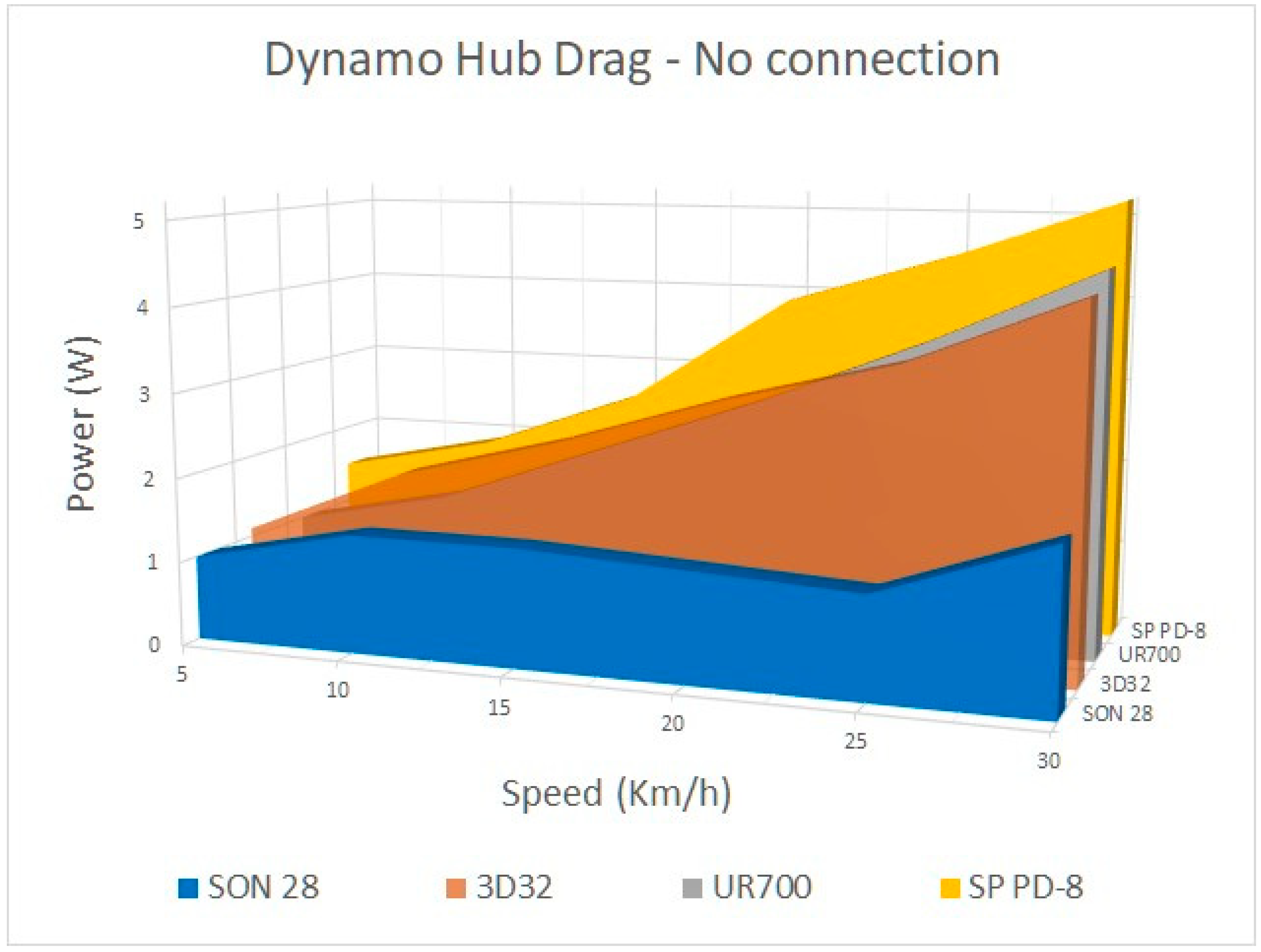
The selection of the hub dynamo can be carried out experimentally in terms of performance. In Figure 2, a comparison of the drag energy according to speed is shown for the hub dynamo models SON28, SP PD-8, UR700, and 3D32. In all models except the SON28, the resistance increases when speed is increased, which means that more energy will be lost at higher speeds.
The frequency generated by the bushing-dynamo depends on the number of pairs of magnetic poles. For SON 28, the number of pole pairs is 13, so the frequency of the alternating signal will be f = 13 n 60 , where n represents the number of revolutions per minute of the wheel. For a 700C wheel (with a diameter of 700 mm), the ground speed by rolling is given by v = 2 π n 60 35 100 . Therefore, the generated frequency is linear at the speed f = 325 3 π v . For speeds close to 50 km/h, frequencies around 80 Hz are reached.
Pedaling resistance on the dynamo hub was measured under fixed laboratory conditions, whose thorough description has been provided in the Supplementary Materials. It was observed that the resistance results depend to a great extent on the tension in the chain, varying a margin of about 3 W between the cases of very tight and not very tight chains. To minimize measurement errors, the chain tension was kept constant and three measurements were made, the result being averaged.
In general, taking into account all the errors, the measurement method, and the influence of the chain tension, we can say that the resistance was measured with an accuracy of 1 W, the speed with an accuracy of 0.1 km/h, and the output parameters with an accuracy of 0.01 V and 0.01 A. Figure 2 shows the results of the laboratory test.

3.1.2. Portable Battery Packs

According to Table 2, the battery pack should be modular, able to be connected to both the USB charger and the solar panels, and easily removable for external use on a bicycle or easily replaceable to extend the useful life of the set. Batteries must supply a large capacity to the system in order to charge a considerable number of devices. Generally, portable battery packs have an actual efficiency between 60% and 70% of the nominal efficiency declared by the manufacturer. Therefore, an appropriate selection would include capacities between 8000 mAh and 10,000 mAh.
Characteristics of the batteries were tested under laboratory conditions, whose thorough descriptions have been provided in the Supplementary Materials.

3.1.3. Solar Panels

Photovoltaic panels allow the energy generated by the sun to be transformed into electrical energy. In the selection of the solar panel, the following technical specifications have been analyzed: (i) output power (the theoretical electrical power that the solar panel is capable of generating); (ii) tolerance (variation in power due to the manufacturing process); (iii) efficiency (the power that 1 m2 of the solar panel is capable of generating when it is receiving irradiation of 1000 W/m2); (iv) number of output ports; (v) relatively small size and weight.
A recent study by Wirecutter Inc. analyzed charging four portable solar panels (ECE 647 (Eceen, Shenzhen, China), HNS-XD-B5V20W (X-dragon, Shenzhen, China) HT-B401A-EU (BigBlue, Hong Kong, China) and AK-A2421011, ANKER, Hong Kong, China) for four hours. This study reveals that the BigBlue 28 W solar panel almost reaches 50 W in four hours.

3.2. Electronic Design of the Integrated System

Using the design specifications from the previous section, in this section we proceed to describe the electronic design of the integrated charging system modules.

3.2.1. Electronics of the USB Charger Module

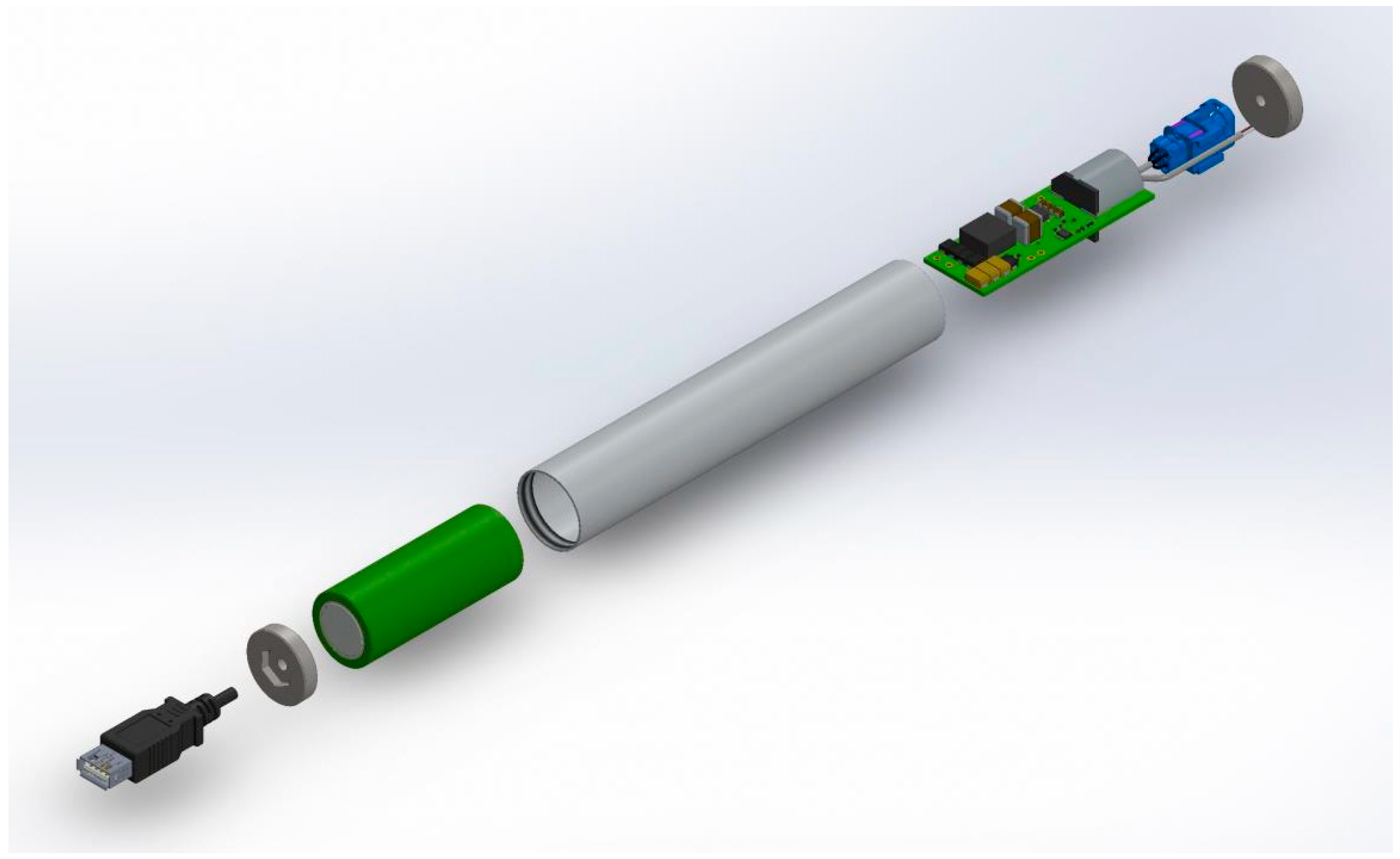
The USB charger is responsible for obtaining the alternating current from the dynamo hub and transforming it into direct current, storing it in the batteries or directing it towards the load. To carry out all these tasks, the electronic circuit in charge of doing each of these tasks will be subdivided into parts. Figure 3 shows the diagram of parts of the USB charger. The AC/DC and DC/DC conversion circuits are mounted in the same tube where the batteries are housed. The printed circuit board does not exceed 26.5 mm in diameter of the tube.
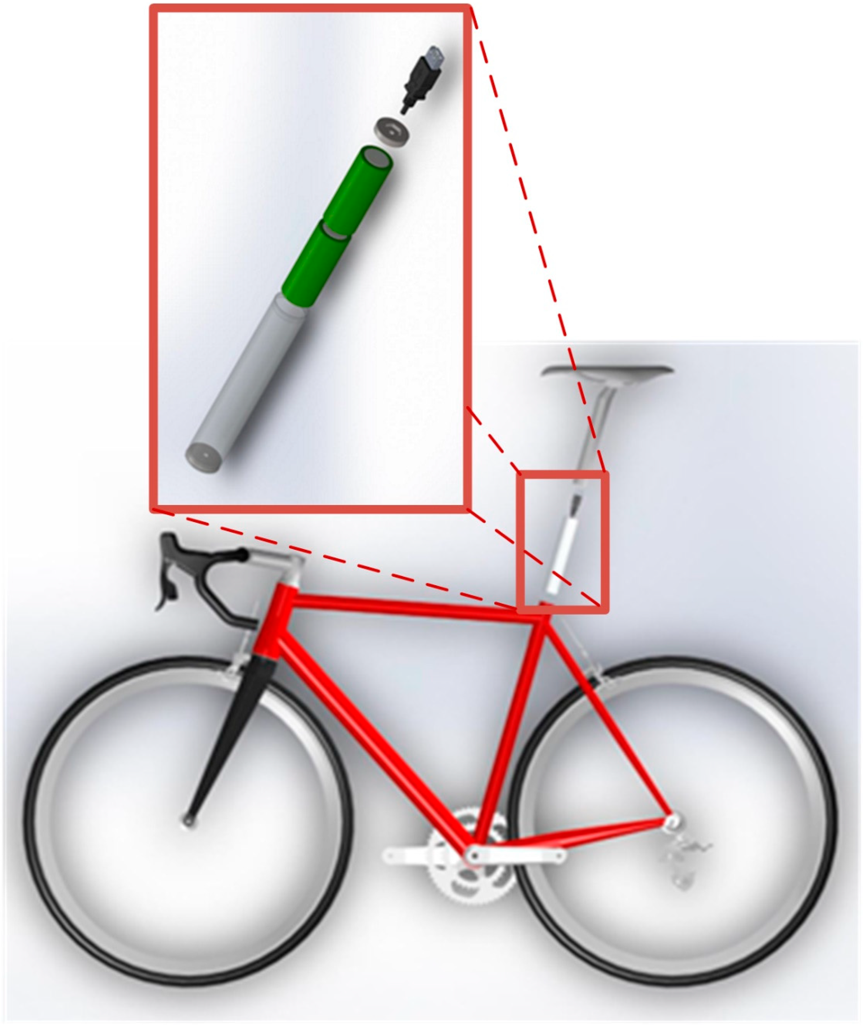
Figure 4 shows the installation of the USB charger on the bicycle.

3.2.2. AC/DC Converter

To guarantee that the system works correctly at speeds below 10 km/h, several experiments were carried out where the values of voltage, current, and generated power were analyzed depending on the speed and the load that was connected to the hub. The tests were carried out in a speed range from 0 km/h to 42 km/h, using loads of 10 Ω, 20 Ω, 30 Ω, 40 Ω, and 50 Ω. Each of these plots are discussed in detail below.
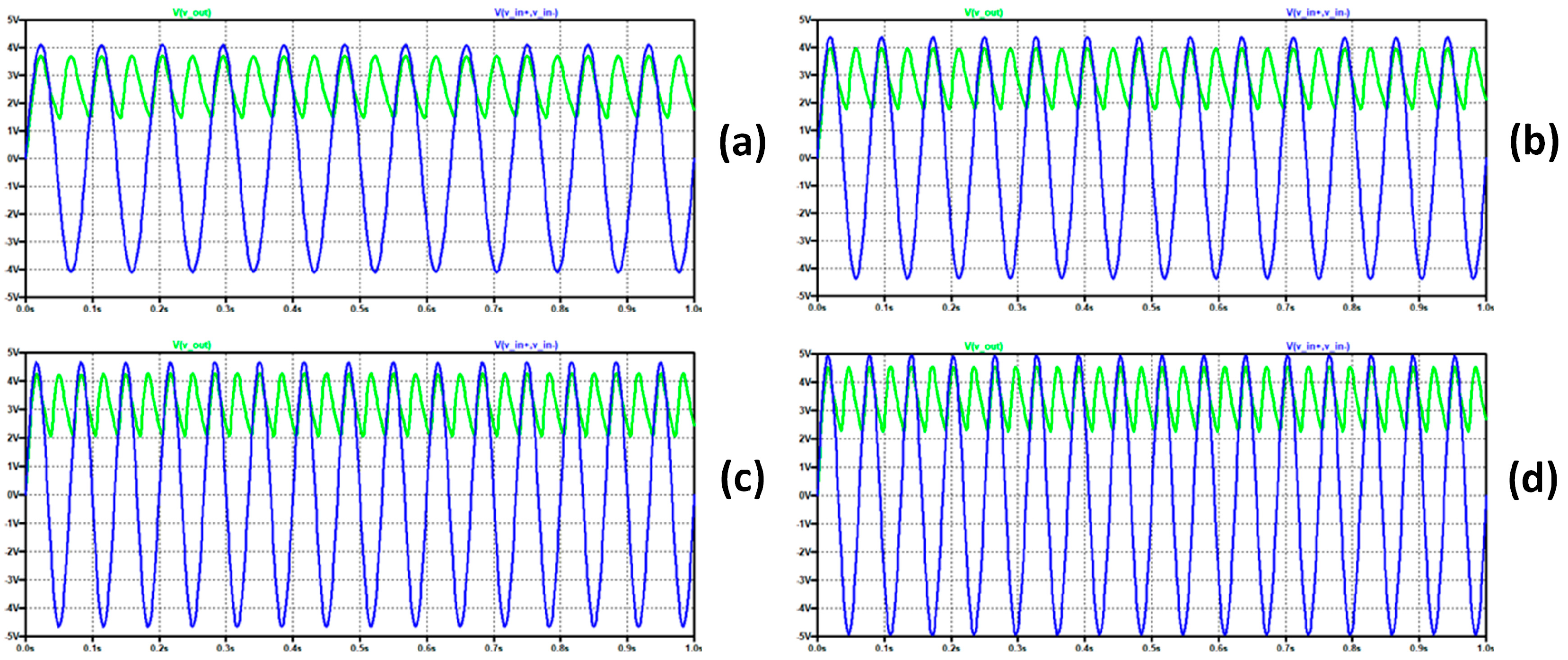
For a 10 Ω load, the average voltage generated by the dynamo follows an experimental curve of the type V v = 5.4   1 e 0.11 v , where v is the speed in kilometers per hour. In Figure 5a–d, the rectified voltage is shown by means of a Schottky diode bridge (with VS-10BQ015HM3 /5BT diodes) for speeds of 7 km/h, 8 km/h, 9 km/h, and 10 km/h, respectively. As shown in those figures, for speed values of 7 km/h, the voltage at the output falls below 1.8 V; for speed values of 8 km/h, the voltage value is still less than 2 V; however, for speed values of 9 km/h, the minimum voltage exceeds 2 V and the maximum value is 4.4 V, so it can be ensured that from 10 km/h the circuit will work correctly.

3.2.3. DC/DC Converter

A switched converter has been used to stabilize the direct current coming from the AC/DC converter. This type of converter has three advantages over linear ones: (i) they exhibit greater energy conversion efficiency; (ii) the thermal energy lost in the circuit is much lower due to the small size of the passive components; (iii) the energy stored in the magnetic field can be transformed into arbitrary output voltages (relative to the input voltage).
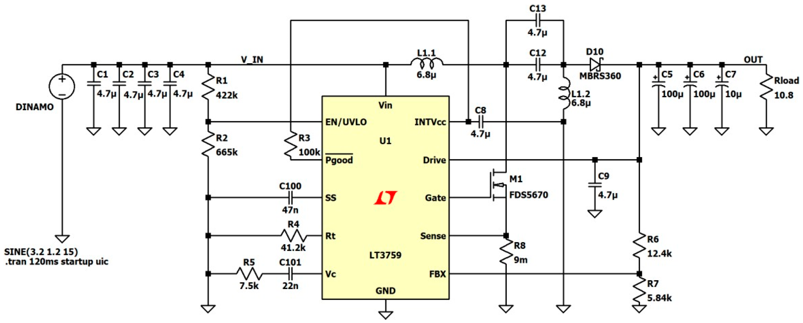
The converter must ensure that the voltage at the converter output is as constant as possible, independent of voltage variations (caused by speed changes occurring in the hub). A Single Ended Primary Inductance Converter (SEPIC) configuration has been chosen as it does not invert the output voltage. It is made up of two capacitors and two coils, of which the input one helps to filter the input current from unwanted harmonics. This switched converter is on the market in an accessible way through integrated circuits of the type LT3759 operating in SEPIC topology with an input range of 1.6–42 V (see Figure 6).
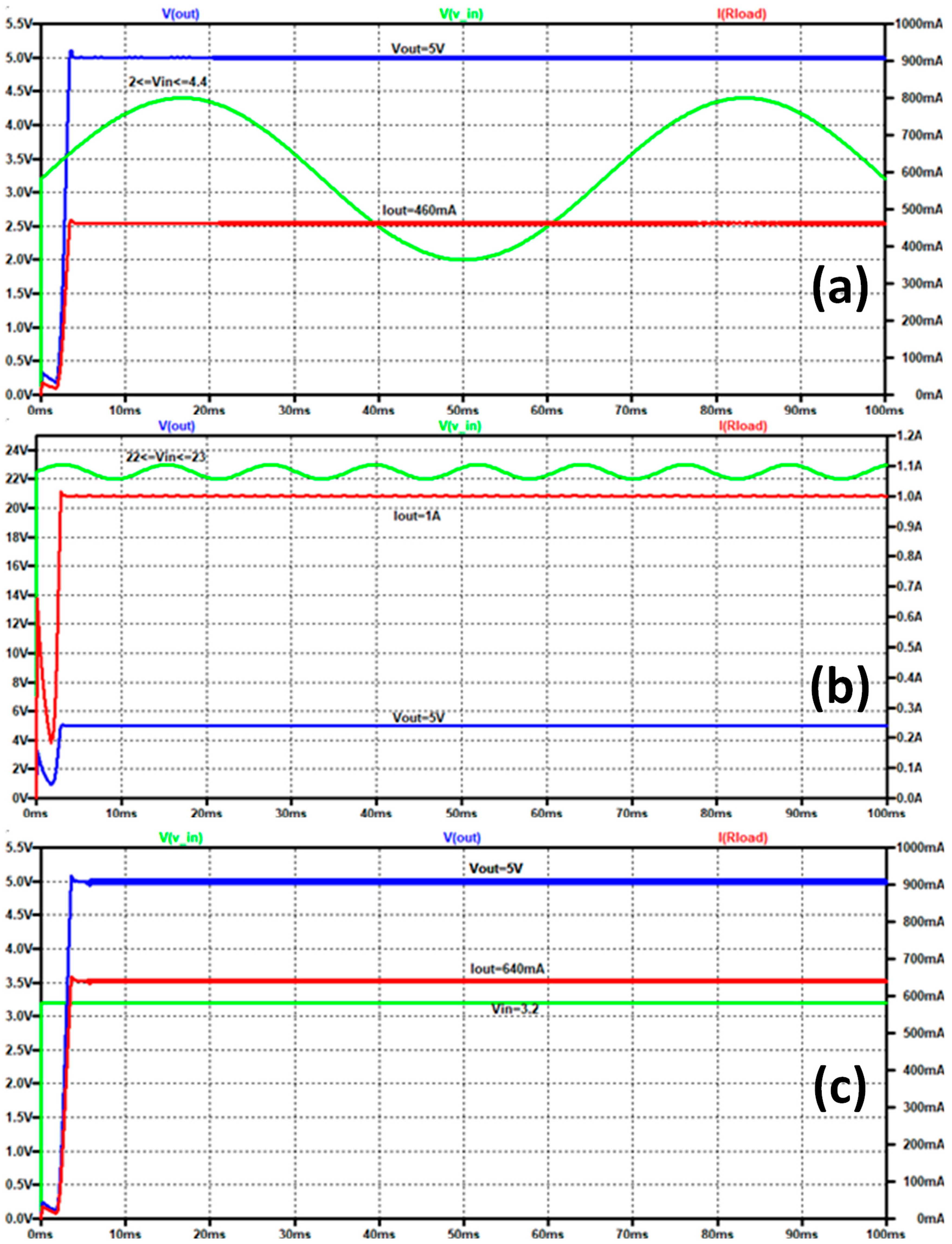
The voltage and current of the LT3759 have been simulated for a minimum input voltage (Figure 7a), maximum input (Figure 7b), and battery connection (Figure 7c). In Figure 7a, with the voltage input values corresponding to a speed of 9 km/h, a voltage of 5 V is obtained at the output to charge the batteries at a current of 460 mA.
In Figure 7b, the operation of the circuit is checked for the maximum voltage values, for speeds close to 45 km/h. The voltage generated by the dynamo bushing is 22 V. It is known that due to the behavior of the bushing, a small ripple voltage is produced, which is unfortunately unknown but in this case is assigned a value of 1 V (peak to peak). It can be seen that for voltage values from 23 V to 22 V the circuit works correctly, with a voltage output of 5 V and a current of 1 A.
Finally, in Figure 7c, the operation of the SEPIC converter has been verified when the voltage source is the battery, which in our case generates 3.6 V of direct current, from which 0.4 V of voltage drop in the diodes is subtracted.

3.3. Batteries

One of the crucial aspects of battery selection is the space available within the USB charger. With the physical design of the charger, an internal diameter in the housing of 26.5 mm has been achieved, so a battery with a diameter of 26 mm and a length of 65 mm has been selected (batteries code 26650). For this size, with the lygte-info application, a search was made for batteries with a charge greater than 5000 mAh, a voltage of around 3.6 V, and a constant current of 0.2 A. With these design requirements, the Shockli 26650 battery was chosen with a nominal voltage per cell of 2.7 V, and a nominal capacity of 5250 mAh. Two other essential parameters are specific energy (energy that a battery can store per unit mass) and energy density (power that a battery can deliver per unit volume). For the Shockli 26650 battery, these parameters are very high compared to other batteries of a similar size (the specific energy is 209 W/kg while the energy density is 548 Wh/L). Specific energy is a critical design parameter since, together with the vehicle energy, it determines the weight of the battery required to reach a given electrical range (for this, a specific energy of around 200 W/kg is achieved in a light battery of about 90 g).
According to the design requirements of the modular charge–storage scheme, the battery pack should provide a capacity in the 8000 mAh to 10,000 mAh range. Choosing the maximum capacity, using two Shockli 5250 mAh batteries exceeds the required value by 500 mAh. This module must be able to be installed both inside the seat tube and in a support for the hand pump. It is for this reason that a female USB type A output connection is used. As shown in Figure 8, the same type of tube has been used for the USB charger with the intention of machining a single element.
The assembly of the batteries on the bicycle is also shown in Figure 8.

3.4. Solar Panel Module

With the intention of being able to use the different modules in sets, a female USB type A was installed in the battery module. Since the BigBlue 28 W solar panel also has a female USB type A output, to charge the battery module with the solar panels, a USB type A cable with two males must be used. On the other hand, the solar panel and the USB charger are connected by an automotive connector with four pins with double USB type A male output.

3.5. Interconnective Wiring

In order to make the interconnection between all the modules, it was necessary to create a specific wiring for this. In this wiring, USB type A connections are used, since the solar panel has a USB type A output and that same connection is added to our battery pack. There are benefits when using USB connections since it facilitates the connection with other devices and is even able to use that cable to charge the USB charger without having to remove it from the bicycle; on the other hand, the USB is not considered a robust connection, its degree of protection is quite low, and in the face of the vibrations of riding a bicycle it can suffer disconnections. It was decided to use an automotive connector from the MATE-AX series with four pins, two of them for the solar panel and the other two for the battery pack this is shown in Figure 9. The benefits of this connector are that no tools are necessary for its connection, it has two tabs that crimp the cables. A cable length of 900 mm is used for the battery pack and 1300 mm for the solar panel.
The connections of the battery pack on the bicycle are shown in Figure 9.

4. Discussion

The comparison between the final design’s features versus the initial design premises and the best features currently available in the market models are presented in a summarized way in Table 3.
As Table 3 shows, most of the design premises fixed in previous phases were met in the final charging–storage system design. The final design candidate works above 9 km/h, can be fed from two sources (pedaling and solar power), the design is modular, and parts are easily replaceable and interchangeable, the storage capacity doubles one of the best models available, the fixing is made inside the frame—which turns it close to invisible—and the estimated cost is way below the cheapest option on the market. In addition, the drag force remains stable from 10 to 25 km/h, which makes its use much more comfortable than any other models available on the market.
However, some of the features demanded were not possible to be met. Due to the extended capacity, the battery weight was doubled, and, therefore, the total weight of the system went above 200 g, which is still quite an acceptable value. Also, no Bluetooth connection capability or managing App was developed, although this could be easily performed in a later prototyping phase.
Table 4 shows the marks obtained by the final designed model applying the same benchmark criteria previously used for commercial models.
As can be seen in Table 4, the final score widely surpasses the highest scores of existing models.

5. Conclusions

In this paper, a modular integrated system has been designed and built capable of producing energy at any speed (even at low speeds of 9 km/h) and storing it for later use. The system is capable of charging its own batteries and powering the devices that are connected to the USB charger from a speed of 9 km/h. An outstanding feature of this design is the modular integration of the different modules: dynamo, USB charger, batteries, solar panel, etc. From a construction point of view, the system allows the simple and efficient integration of all components using only one extension cable. Finally, the end product is ergonomic, easy to use, and priced below the market. A Li-ion battery (IMR 26650) with a capacity of 5250 mAh has been used with a voltage of 3.7 V, and at a price much lower than the market price (approximately forty-five dollars). This battery allows more than 500 charge cycles. Although LiFePo4 batteries offer much higher life cycle values, they do so at the cost of a sacrifice in weight and volume [51,52].
Other very valuable aspects of this design have been the final appearance (maximum integration in the bicycle with the least visibility of the product); the ability to replace batteries by the user; the Bluetooth connectivity; and the power output (about 2 A of output are supplied). Although the total weight is 0.2 kg, this is similar to the model with the highest output current (the Forumslader provides 2.9 A), although in the design presented, the capacity of the batteries has been doubled. The modular integration with different devices such as the battery pack or solar panels also stands out. Current models on the market do not perform this integration.
The design can be improved in the future by creating a tailored solar panel. Also, the appearance can be improved by better encapsulation and USB connection while maintaining a degree of IP protection. The creation of an App for mobile devices would be another added value to the USB charger. This would require an electronic redesign to integrate a Bluetooth communication module. Finally, the cost of the battery module must be reduced because, although it offers some installation features on the bicycle that conventional products do not have, this device is slightly above the market value.

Supplementary Materials

The following supporting information can be downloaded at: https://www.mdpi.com/article/10.3390/app14020523/s1.

Author Contributions

Conceptualization, J.S.V. and J.A.V.-M.; methodology, J.S.V., F.C. and J.I.M.-M.; software, J.A.V.-M.; validation, J.S.V., J.A.V.-M., F.C. and J.I.M.-M.; formal analysis, F.C. and J.I.M.-M.; investigation, J.S.V. and J.A.V.-M.; resources, F.C. and J.I.M.-M.; data curation, J.A.V.-M. and J.I.M.-M.; writing—original draft preparation, J.S.V., J.A.V.-M., F.C. and J.I.M.-M.; writing—review and editing, J.S.V., J.A.V.-M., F.C. and J.I.M.-M.; visualization, J.A.V.-M. and J.S.V.; supervision, F.C. and J.I.M.-M.; project administration, F.C.; funding acquisition, J.S.V. All authors have read and agreed to the published version of the manuscript.

Funding

This research received no external funding.

Institutional Review Board Statement

Not applicable.

Informed Consent Statement

Not applicable.

Data Availability Statement

Data are contained within the article and supplementary materials.

Conflicts of Interest

The authors declare no conflicts of interest.

References

  1. Roskilly, A.P.; Palacin, R.; Yan, J. Novel technologies and strategies for clean transport systems. Appl. Energy 2015, 100, 563–566. [Google Scholar] [CrossRef]
  2. Wolf, S.; Teitge, J.; Mielke, J.; Schütze, F.; Jaeger, C. The European Green Deal—More Than Climate Neutrality. Intereconomics 2021, 56, 99–107. [Google Scholar] [CrossRef] [PubMed]
  3. Siddi, M. The European Green Deal: Assessing Its Current State and Future Implementation; University of Cagliari: Cagliari, Italy, 2020. [Google Scholar]
  4. Mei, Z.; Wang, D.; Chen, J.; Wang, W. Investigation of bicycle travel time estimation using bluetooth sensors for low sampling rates. Promet-Traffic Transp. 2014, 26, 383–391. [Google Scholar] [CrossRef]
  5. Johansson, C.; Lövenheim, B.; Schantz, P.; Wahlgren, L.; Almström, P.; Markstedt, A.; Strömgren, M.; Forsberg, B.; Sommar, J.N. Impacts on air pollution and health by changing commuting from car to bicycle. Sci. Total Environ. 2017, 584–585, 55–63. [Google Scholar] [CrossRef] [PubMed]
  6. Chen, C.-A.; Lee, H.-L. How to promote bike tourism globally. Tour. Hosp. Manag. 2017, 23, 1–16. [Google Scholar] [CrossRef]
  7. Alwyn, Y.W.S.; Faizal, M. Bicycle Powered Mobile Phone Charger. In Proceedings of the 14th EURECA 2020—International Engineering and Computing Research Conference “Shaping the Future through Multidisciplinary Research”, Subang Jaya, Malayasia, 25 November 2020; p. 03018. [Google Scholar]
  8. Kiefer, C.; Behrendt, F. Smart e-bike monitoring system: Real-time open source and open hardware GPS assistance and sensor data for electrically-assisted bicycles. IET Intell. Transp. Syst. 2016, 10, 79–88. [Google Scholar] [CrossRef]
  9. Fishman, E.; Cherry, C. E-bikes in the Mainstream: Reviewing a Decade of Research. Transp. Rev. 2016, 36, 72–91. [Google Scholar] [CrossRef]
  10. Shashank, R.; Akshay, V.; Ramesh, S.; Nithin, B.G.; Ravi, K.S.; Krishna, S.A.M. Design and fabrication of solar powered bicycle. J. Phys. Conf. Series 2021, 2070, 012208. [Google Scholar] [CrossRef]
  11. Asrori, A.; Rohman, F.; Faizal, E.; Karis, M. The design and Performance Investigation of Solar E-Bike using flexible solar panel by different battery charging controller. Int. J. Mech. Prod. Eng. Res. Dev. IJMPERD 2020, 10, 14431–14442. [Google Scholar]
  12. Apostolou, G.; Reinders, A.; Geurs, K. An overview of existing experiences with solar-powered e-bikes. Energies 2018, 11, 2129. [Google Scholar] [CrossRef]
  13. Reddy, P.R.; Gowda, K.S.S.; Charitha, S.; Mahalakshmi, R. Review and Redesign of Pedal Energy-Solar Power Augmented Hybrid Bicycle. In Proceedings of the 2020 Third International Conference on Smart Systems and Inventive Technology (ICSSIT), Tirunelveli, India, 20–22 August 2020; pp. 376–380. [Google Scholar]
  14. Brenna, M.; Falvo, M.C.; Foiadelli, F.; Martirano, L.; Massaro, F.; Poli, D.; Vaccaro, A. Challenges in energy systems for the smart-cities of the future. In Proceedings of the 2012 IEEE International Energy Conference and Exhibition (ENERGYCON), Florence, Italy, 9–12 September 2012; pp. 755–762. [Google Scholar]
  15. Cecconi, V.; Di Dio, V.; Di Tommaso, A.O.; La Cascia, D.; Miceli, R. Test bench realization and application of specific working cycles for the characterization of wheelchair electrical drives. In Proceedings of the 2006 IEEE International Symposium on Industrial Electronics, Montreal, QC, Canada, 9–13 July 2006; pp. 2188–2193. [Google Scholar]
  16. Tsai, C.-C.; Lin, W.-M.; Lin, C.-H.; Wu, M.-S. Designing a fast battery charger for electric bikes. In Proceedings of the 2010 International Conference on System Science and Engineering, Taipei, Taiwan, 1–3 July 2010; pp. 385–389. [Google Scholar]
  17. Boscaino, V.; Livreri, P.; Marino, F.; Minieri, M. Linear-non-linear digital control for dc/dc converters with fast transient response. Int. J. Power Energy Syst. 2009, 29, 38–47. [Google Scholar] [CrossRef]
  18. Yun, J.J.; Choe, H.J.; Hwang, Y.H.; Park, Y.K.; Kang, B. Improvement of Power-Conversion Efficiency of a DC–DC Boost Converter Using a Passive Snubber Circuit. IEEE Trans. Ind. Electron. 2012, 59, 1808–1814. [Google Scholar] [CrossRef]
  19. Dannier, A.; Rizzo, R. An overview of Power Electronic Transformer: Control strategies and topologies. In Proceedings of the International Symposium on Power Electronics Power Electronics, Electrical Drives, Automation and Motion, Sorrento, Italy, 20–22 June 2012; pp. 1552–1557. [Google Scholar]
  20. ElMenshawy, M.; Massoud, A. Development of Modular DC-DC Converters for Low-Speed Electric Vehicles Fast Chargers. Alex. Eng. J. 2021, 60, 1067–1083. [Google Scholar] [CrossRef]
  21. Bani Ahmad, A.; Ooi, C.A.; Ishak, D.; Abdullah, M.N. Optimal cell utilisation with state-of-charge balancing control in a grid-scale three-phase battery energy storage system: An experimental validation. Alex. Eng. J. 2022, 61, 9043–9059. [Google Scholar] [CrossRef]
  22. Viswanatha, V. Microcontroller based bidirectional buck–boost converter for photo-voltaic power plant. J. Electr. Syst. Inf. Technol. 2018, 5, 745–758. [Google Scholar]
  23. Sudarshan, B.S.; Arunkumar, G. SiC switch-based isolated DC-DC converter for simultaneous charging of Li-ion batteries of different voltage ratings for low- and medium-power electric vehicle battery charging application. Int. J. Circuit Theory Appl. 2023, 51, 5348–5400. [Google Scholar] [CrossRef]
  24. Tran, V.-L.; Tran, N.-T.; Yu, S.-H.; Park, Y.; Choi, W. Design of a nonisolated fuel cell boost charger for lithium polymer batteries with a low output ripple. IEEE Trans. Energy Convers. 2014, 30, 605–614. [Google Scholar] [CrossRef]
  25. Chandrasekaran, R.; Reddy, M.S.K.; Selvajyothi, K.; Raja, B. Design of bidirectional DC-DC converters and controllers for hybrid energy sources in electric vehicles. In Power Converters, Drives and Controls for Sustainable Operations; Wiley: Hoboken, NJ, USA, 2024; pp. 437–461. [Google Scholar] [CrossRef]
  26. Kushwaha, R.; Khadkikar, V.; Edpuganti, A. Electric Vehicle On-Board Fast Charging Through Converter Maximum Switch Utilization. IEEE Trans. Power Electron. 2024, 39, 998–1014. [Google Scholar] [CrossRef]
  27. Khan, S.; Awan, M.J. A generative design technique for exploring shape variations. Adv. Eng. Inform. 2018, 38, 712–724. [Google Scholar] [CrossRef]
  28. Volstad, N.L.; Boks, C. On the use of Biomimicry as a Useful Tool for the Industrial Designer. Sustain. Dev. 2012, 20, 189–199. [Google Scholar] [CrossRef]
  29. Feng, Y.; Zhao, Y.; Zheng, H.; Li, Z.; Tan, J. Data-driven product design toward intelligent manufacturing: A review. Int. J. Adv. Robot. Syst. 2020, 17, 1729881420911257. [Google Scholar] [CrossRef]
  30. Stegall, N. Designing for sustainability: A philosophy for ecologically intentional design. Des. Issues 2006, 22, 56–63. [Google Scholar] [CrossRef]
  31. Kankainen, A. UCPCD: User-centered product concept design. In Proceedings of the 2003 Conference on Designing for User Experiences, San Francisco, CA, USA, 6–7 June 2003; pp. 1–13. [Google Scholar]
  32. Still, B.; Crane, K. Fundamentals of User-Centered Design: A Practical Approach; CRC Press: Boca Raton, FL, USA, 2017. [Google Scholar]
  33. Rubin, J.; Chisnell, D. Handbook of Usability Testing: How to Plan, Design, and Conduct Effective Tests; John Wiley & Sons: Hoboken, NJ, USA, 2008. [Google Scholar]
  34. Arntzen, C. The Bicycle-Powered Smartphone Charger; California Polytechnic State University: San Luis Obispo, CA, USA, 2013. [Google Scholar] [CrossRef]
  35. Affam, A.; Mohd-Mokhtar, R. Application of Three Independent Sources to Mobile Phone Charging During Emergencies. In Proceedings of the 10th International Conference on Robotics, Vision, Signal Processing and Power Applications, Penang, Malaysia, 2 April 2019; pp. 261–268. [Google Scholar]
  36. Schleyer, T.K.L.; Thyvalikakath, T.P.; Hong, J. What is user-centered design? J. Am. Dent. Assoc. 2007, 138, 1081–1082. [Google Scholar] [CrossRef] [PubMed]
  37. Brunner, J.; Chuang, E.; Goldzweig, C.; Cain, C.L.; Sugar, C.; Yano, E.M. User-centered design to improve clinical decision support in primary care. Int. J. Med. Inform. 2017, 104, 56–64. [Google Scholar] [CrossRef] [PubMed]
  38. Lyon, A.R.; Koerner, K. User-centered design for psychosocial intervention development and implementation. Clin. Psychol. Sci. Pract. 2016, 23, 180. [Google Scholar] [CrossRef] [PubMed]
  39. Popescu, D.; Roibu, H.; Manta, F.L.; Unguritu, O.; Marian, M. Design of a Mobile Robot to Work in Special Environments. In Proceedings of the EPE 2020—Proceedings of the 2020 11th International Conference and Exposition on Electrical and Power Engineering, Iasi, Romania, 22–23 October 2020; pp. 226–231. [Google Scholar]
  40. Lowdermilk, T. User-Centered Design: A Developer’s Guide to Building User-Friendly Applications; O’Reilly Media, Inc.: Sebastopol, CA, USA, 2013. [Google Scholar]
  41. Al Maghraoui, O.; Vallet, F.; Puchinger, J. Recommendations for a User-Centered Design of Mobility Solutions. In The Robomobility Revolution of Urban Public Transport: A Social Sciences Perspective; Springer: Berlin/Heidelberg, Germany, 2021; pp. 133–152. [Google Scholar]
  42. Mao, J.-Y.; Vredenburg, K.; Smith, P.W.; Carey, T. The state of user-centered design practice. Commun. ACM 2005, 48, 105–109. [Google Scholar] [CrossRef]
  43. Mathur, S.; Janaudis-Ferreira, T.; Hemphill, J.; Cafazzo, J.A.; Hart, D.; Holdsworth, S.; Lovas, M.; Wickerson, L. User-centered design features for digital health applications to support physical activity behaviors in solid organ transplant recipients: A qualitative study. Clin. Transplant. 2021, 35, e14472. [Google Scholar] [CrossRef]
  44. Gray, C.S.; Khan, A.I.; Kuluski, K.; McKillop, I.; Sharpe, S.; Bierman, A.S.; Lyons, R.F.; Cott, C. Improving patient experience and primary care quality for patients with complex chronic disease using the electronic patient-reported outcomes tool: Adopting qualitative methods into a user-centered design approach. JMIR Res. Protoc. 2016, 5, e5204. [Google Scholar]
  45. Jokela, T.; Iivari, N.; Matero, J.; Karukka, M. The standard of user-centered design and the standard definition of usability: Analyzing ISO 13407 against ISO 9241-11. In Proceedings of the Latin American Conference on Human-Computer Interaction, Rio de Janeiro, Brazil, 17–20 August 2003; pp. 53–60. [Google Scholar]
  46. Arbour, M. New Cinq Plug5 Pure: Dynamo Power Perfected. 2020. Available online: https://bikepacking.com/news/cinq-plug5-pure/ (accessed on 6 January 2024).
  47. NC-17 Connect. NC-17 Connect AppCon 3000. NC-17 Connect. Available online: https://www.appcon3000.de/products/nc-17-connect-appcon-3000 (accessed on 6 January 2024).
  48. Lumi-Con-Bike Energy Harvester. Available online: https://www.lumi-con.de/prod_USB_eng.html (accessed on 6 January 2024).
  49. Automatiklader V5: Forumslader. Available online: https://www.bumm.de/en/products/stromversorgung/parent/3610/produkt/361bw.html (accessed on 6 January 2024).
  50. USB-WERK-Busch + Müller EN. Available online: https://www.forumslader.de/aeltere-versionen/automatiklader-v5/ (accessed on 6 January 2024).
  51. Majeau-Bettez, G.; Hawkins, T.R.; Strømman, A.H. Life Cycle Environmental Assessment of Lithium-Ion and Nickel Metal Hydride Batteries for Plug-In Hybrid and Battery Electric Vehicles. Environ. Sci. Technol. 2011, 45, 4548–4554. [Google Scholar] [CrossRef]
  52. Takahashi, M.; Ohtsuka, H.; Akuto, K.; Sakurai, Y. Confirmation of Long-Term Cyclability and High Thermal Stability of LiFePO[sub 4] in Prismatic Lithium-Ion Cells. J. Electrochem. Soc. 2005, 152, A899. [Google Scholar] [CrossRef]
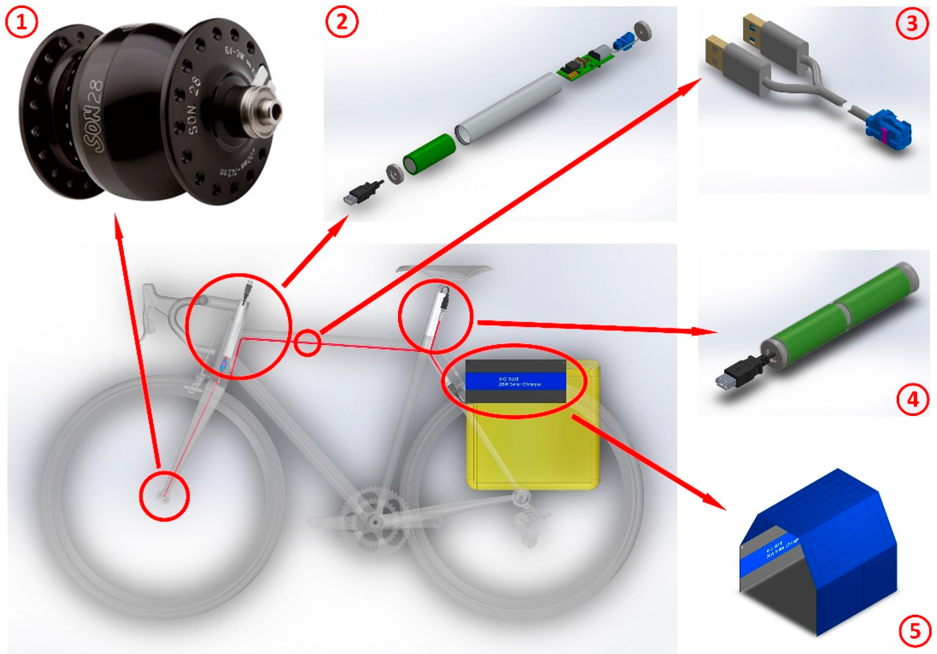
Figure 1. Modular diagram of the sustainable bike charging system: ① Hub Dynamo, ② USB Charger, ③ Interconnection Cable, ④ Extension of Batteries, ⑤ Solar Panel.
Applsci 14 00523 g001
Figure 2. Energy–Speed graph for the different hubs.
Applsci 14 00523 g002
Figure 3. Exploded isometric view for USB charger.
Applsci 14 00523 g003
Figure 4. Exploded view: installation of the USB charger.
Applsci 14 00523 g004
Figure 5. Dynamo voltage (v_in+, v_in− /blue) and load voltage (v_out/green) for (a) V = 7 km/h; (b) V = 8 km/h; (c) V = 9 km/h; (d) V = 10 km/h.
Applsci 14 00523 g005
Figure 6. Mounting scheme for LT3759.
Applsci 14 00523 g006
Figure 7. (a) Output voltage and current for minimum input voltage; (b) output voltage and current for maximum input voltage; (c) output voltage and current for battery input voltage.
Applsci 14 00523 g007
Figure 8. Exploded detail of the extension batteries. The batteries are placed inside the seat’s shank tube for a more compact installation.
Applsci 14 00523 g008
Figure 9. Module interconnection cable plugs detail and cable distribution for battery, solar panel, and USB charger connection.
Applsci 14 00523 g009
Table 1. Technical characteristics of the most-used charging–storage systems on the market.
ModelBattery TypeCapacity [mAh]
Voltage [V]
Temperature Range [°C]LifetimePrice [EUR]
Plug5 Plus [46]LiFePO31100
3.2
−15–60>2000 cycles259
Appcon3000 [47]Li-ion: LG INR186503000
3.63
0–45>300 cycles229
USB-P5 [48]Li-ion: Samsung INR18650-25R2 × 2500
3.6
0–60>250 cycles95
Forumslader V5 Ahead [49]LiMn: Efest IMR183503 × 700
3.7
0–60>250 cycles227
USB-Werk [50]LiFePO32 × 150
3.2
−15–60>2000 cycles80–95
Table 2. Market model benchmarking and evaluation scores.
ModelAestheticsCapacityCurrent OutputWeightBattery
Replacement
Solar ChargingStable Drag ForceBluetooth/AppPriceTotal
Plug5 Plus [46]31
1100 mAh
1
1.2 A
1
195 g
00010
EUR 259
7
Appcon3000 [47]23
3000 mAh
2
2.0 A
3
102 g
00011
EUR 229
12
USB-P5 [48]14
5000 mAh
1
1.5 A
2
150 g
10003
EUR 95
12
Forumslader V5 Ahead [49]32
2100 mAh
3
2.9 A
1
210 g
10011
EUR 227
12
USB-Werk [50]10
300 mAh
0
0.5 A
4
53 g
10004
EUR 80
10
Table 3. Comparison between features available in best comparable market models, user desirable features, and final design.
Best Comparable Market ModelUser DesirableDesigned Product
USB charger
  • Working speed
Working above 12 km/hWorking above 10 km/hWorking above 9 km/h
  • Design
As provided by manufacturerModular and interchangeableModular and interchangeable
  • Housing
Fixed outside the frameFixed inside the frameFixed inside the frame
  • Generation sources
1 (hub dynamo)2 (hub dynamo/solar)2 (hub dynamo/solar)
  • Drag force
VariableStable at any speedStable from 10 to 25 km per h
Battery pack
  • Design
As provided by manufacturerModular with replaceable partsModular with replaceable parts
  • Replacement
Must dismount carcass/not sold separatelyEasy to replace by user/sold separatelyEasy to replace by user/sold separately
  • Housing
Fixed outside the frameFixed inside the frameFixed inside the shank’s tube
  • Connection sources
1 (USB charger OR solar panel)2 (USB charger AND solar panel)2 (USB charger AND solar panel)
  • Life cycle/weight
300 cycles/150 gAbove 300 cycles/less than 150 g500 cycles/around 200 g
  • Design capacity
Around 5000 mAhAround 8000 mAhAround 10,500 mAh
Solar charging system
  • Output ports
Single USB-A outputDouble USB-A outputDouble USB-A output
  • Output power
Above 28 WAbove 20 WAbove 28 W
  • Efficiency
21.5–23.5%Above 20%21.5–23.5%
  • Size and weight
Small and lowSmall and lowSmall and low
Interconnect wiring
  • Features
Does not existUniversal and sturdy
No tools needed to connect
USB (universal) and MATE-AX (sturdy)
Pricing
  • Pricing
EUR 80–260 Around EUR 80Around EUR 45 (100 units)
Table 4. Designed model evaluation scores.
ModelAestheticsCapacityCurrent OutputWeightBattery
Replacement
Solar ChargingStable Drag ForceBluetooth/AppPriceTotal
Final Design24
10,500 mAh
2
2.0 A
1
200 g
11104
EUR 45
16
Disclaimer/Publisher’s Note: The statements, opinions and data contained in all publications are solely those of the individual author(s) and contributor(s) and not of MDPI and/or the editor(s). MDPI and/or the editor(s) disclaim responsibility for any injury to people or property resulting from any ideas, methods, instructions or products referred to in the content.