Article

Digital Twin-Based Clamping Sequence Analysis and Optimization for Improved Geometric Quality

1
Department of Industrial and Materials Science, Chalmers University of Technology, 41296 Gothenburg, Sweden
2
Mercedes-Benz AG, 71063 Sindelfingen, Germany
3
Institute of Machine Elements and Machine Design, Technical University of Dresden, 01062 Dresden, Germany
*
Author to whom correspondence should be addressed.
Appl. Sci. 2024, 14(2), 510; https://doi.org/10.3390/app14020510
Submission received: 4 December 2023 / Revised: 29 December 2023 / Accepted: 3 January 2024 / Published: 6 January 2024

Abstract

:
Geometric deviation associated with the assembly of sheet metal is a general concern for manufacturers. The typical assembly step involves a sequence of events that exert forces on the parts to enforce them to the nominal condition and to connect the parts together. The simulation and optimization of the assembly steps often neglect the sequence of operations due to the problem and computation complexity. This paper investigates the influence of the clamping sequence in the body-in-white (BIW) manufacturing process on the geometrical quality of the assembly. An approach for modeling clamping sequences for non-rigid variation simulation is introduced in a digital twin context, taking the part deviation into consideration. An optimization method is proposed to achieve minimum geometric deviation after clamping the parts and welding them together. The method is successfully applied on two reference assemblies, and the results show that the sequence of clamping can impact the total geometric deviation up to 31%. Combining clamping and welding sequence optimization can enhance the quality improvement to 77% after releasing the assembly from the fixture and springback.

1. Introduction

Geometric variation is unavoidable in the manufacturing process of sheet metal assemblies in the automotive industry, which affects the quality as well as the cost of the products. Generally, the geometric variation in the body-in-white (BIW) assembly process is divided into three types: part variation, stemming from the fabrication process of the individual components of the assembly structure; tool variation, such as the welding gun distortion; and fixture variation [1]. Traditionally, worst-case analysis, statistical analysis, and Monte Carlo (MC) simulation methods are used to calculate the tolerance accumulation when parts are assembled together [2]. To improve the analyzing efficiency for parts with complex geometry and 3D deviations, numerical simulation methods are applied to study the effects of geometric variation in modern automotive manufacturing processes.

1.1. Variation Simulation

Part, tool, and fixture variations are summarized as part variations and process variations. In modern automotive engineering, to reduce the development time and physical experimentation during the prototyping and verification phase, digital tools are used to simulate the geometric variation in complex assemblies with extensive tolerance chains. Commercial computer-aided tolerancing (CAT) software packages, e.g., RD&T [3] and 3DCS [4], have been introduced, taking into account the aforementioned tolerances to perform variation simulation based on the defined positioning points and assigned tolerances.
In sheet metal assemblies, the parts are bent and deformed during the assembly process. Therefore, the positioning system of the assembly, which ideally is reflected precisely in the assembly station fixture, allows for over-constrained conditions [5]. Often, several clamping points are considered as support points during the assembly process, mainly to lock the normal-to-surface direction of the formed sheet metal parts. When dealing with the non-rigid parts, the assembly process is typically composed of four steps: positioning the parts in the fixture; clamping the parts; fastening, i.e., joining the parts together; and releasing the assembly from the fixture. This process is referred to as Position, Clamp, Fasten, Release (PCFR) [6].
Previous studies have focused on part variation representation and its contribution to final assembly variation [7]. Representing the part variation in digital models through skin model shapes has also been considered [8]. Assembly process variation simulation has also been introduced, analyzing the impact of the fixture design [9,10,11], clamping [12,13,14], and welding distortion [15,16,17,18]. Similarly, the optimization perspectives on each step during the assembly process have been studied [7,19,20]. In the following, the optimization perspective regarding the assembly process, more specifically concerning the clamping step, is presented.

1.2. Influence of Clamping Process in Quality Assurance

During the assembly process of sheet metals, the clamping step is performed to ensure that the parts are locked in the normal-to-surface direction. There are two parameters associated with the clamping step: firstly, the position of the clamping points and, secondly, the sequence of applying the clamping forces to the assembly. Optimization of the clamping step during the assembly process has also been studied based on these two parameters.
Qin et al. have considered the impact of the clamping sequence on the design of a fixture. They have introduced an approach for analyzing the clamping sequence on the contact force distribution and machining accuracy of rigid bodies [21]. Yu et al. have considered a computational approach for estimating the buckling effect during welding with respect to the clamping conditions [22]. Xie and Hsieh have studied clamping and welding sequence optimization to minimize the cycle time and assembly deformation variation. They have considered a genetic algorithm (GA) for this optimization task [23]. Several studies have considered the fixture layout optimization, considering the nominal geometry [24,25]. The effect of the clamping forces on the working object has been studied, and the minimum clamping forces are identified [26]. In another study, the GA optimization algorithm is considered for optimizing the fixture layout and the clamping sequence [27] on a simple geometry workpiece. Further studies have shown that relying on evolutionary algorithms for joining sequence optimization of non-rigid assemblies is computationally expensive, as the objective function involves the Finite Element Method (FEM) and MC simulations [19]. In another study, Raghu and Melkote have taken an analytical approach to model the impact of a clamping sequence on a solid workpiece location error [12]. The developed model has shown a 20% prediction error in workpiece location and reaction forces. The influence of the clamping condition of the welding distortion has been studied; however, the sequential process is not taken into consideration [28,29].
The previous research has mostly considered applying a GA to optimize the clamping sequence on solid bodies or sheet metal assemblies. The studies are divided into taking the part variation into consideration or solely focusing on identifying clamping sequences on nominal geometries. In this paper, a method has been established to analyze the clamping sequence and optimize the sequences time-efficiently with a digital twin, taking into account individual part deviation.

1.3. Geometry Assurance Digital Twin

Digital twin-based manufacturing and process optimization has been introduced recently, controlling the manufacturing processes in real time, utilizing a digital counterpart of the process [30,31,32,33]. For controlling the geometric quality of the assembly process, the geometry assurance digital twin concept has been introduced, steering the sheet metal assembly process [34]. The digital twin for the geometry assurance of sheet metal assemblies is a digital replica of the assembly system, including the physics of the process, to steer and control the assembly of the sheet metals. This twin relies on the 3D-scanned geometries of the incoming fabricated components. Based on this information, the parts are being matched for the optimal geometric outcome. Part matching has been considered as a Selective Assembly process for the sheet metal parts [35]. Later, the shimming process for the fixture locators is optimized based on the incoming geometric error of the parts in the fixture [36]. While the parts are being held in the fixture, the welding sequence is being optimized. In the twin, the critical welding points are being identified, and the sequence is deterministically decided for the existing error after fixturing [37]. A rapid sequence optimization approach has been specifically developed for this purpose [38]. In the geometry assurance twin, the clamping step has been considered to take place simultaneously with the locating step. In this paper, we introduce a computationally efficient clamping sequence analysis and optimization for this twin, taking into consideration the individual part deviation based on the 3D-scanned geometries.

1.4. Scope of the Paper

The clamping operation and the sequence of applying the clamp forces is a crucial step for the assembly of sheet metals, affecting the springback behavior and final deformation of the assemblies. Optimizing the clamping sequences is computationally heavy, as the problem is combinatorial and involves FEM simulation. Previous research has focused on a GA for the optimization of the clamping sequences on simpler geometries, and often part variation is neglected. In this paper, a modeling, simulation, and computationally efficient optimization approach for the clamping sequence analysis has been introduced utilizing the geometry assurance digital twin for individualized assembly lines, taking into account individual part deviation through 3D-scanned geometries. The method has been applied to two reference assemblies, and the follow-up assembly operations have been analyzed. Section 1 provides a background to the problem. Section 2 introduces the proposed method, followed by the description of the reference assemblies in Section 3. The clamping sequence optimization and analysis are put forward in Section 4, and the discussions around the achieved results are presented in Section 5. Finally, the conclusions based on the analysis of the result are drawn in Section 6.

2. Method

The state-of-the-art assembly modeling for clamping and welding sequence analysis is established based on the Method of Influence Coefficient (MIC) [5] principles for sheet metal assemblies. The established method and the sequence optimization procedure are introduced below.

2.1. Proposed Clamping Sequence Model

To model the assembly process in the geometry assurance digital twin, Section 1.3, the nominal parts are integrated with the corresponding nodal displacements from the 3D-scanned data. This way, each mesh node in the assembly is associated with an offset. The parts are then positioned in a fixture. There are two types of fixturing elements during the modeling process: the orientation elements, where the in-plane movements are locked, and the clamping elements, where the normal-to-surface movements are locked. The positioning of the non-rigid parts is based on the N-2-1 positioning systems, where over-constraining (for rigid bodies, the 3-2-1 positioning systems are used to lock the 6 degrees of freedom; here, N can have a value larger than 3) is allowed in the normal-to-surface direction to compensate for bending, e.g., due to gravitational force. The overview of the enhanced MIC approach is presented in Figure 1.
Utilizing the stress–strain law of the elastic bodies, the deformations are captured,
f = K u ,
where f is the force, K is the global stiffness matrix, and u is the vector of the initial gaps. Similarly, the clamping and joining forces are calculated. Because, during the assembly, virtual penetrations between the components need to be constrained, contact modeling is utilized to capture the contact forces. The contact forces are captured by defining the computational nodes, representing the areas where the parts are in contact nominally. During assembly, the penetration is checked in the following nodes, and the reaction forces are applied to the assembly. The contact reaction forces are derived through the quadratic optimization of the minimum forces required to bring out the surfaces from the penetrated state.
minimize F 1 2 f T Sf + f T u subject to Sf u f 0 .
Here, S is the assembly sensitivity matrix derived from the fixtured assembly expression,
K u = f cl + f c + f w ,
where f cl is the clamping force, f c is the contact force, and f w is the force required for welding the parts together. In this formulation, S = K 1 holds only with respect to the relevant rows in the stiffness matrix [5]. The solution to the optimization problem (2) is achieved by an interior point solver. This solver breaks down the quadratic program into a set of linear problems by introducing slack variables. This unconstrained problem is then solved iteratively by the Mehrotra predictor–corrector method [39]. The fixture is a stiff part (rigid part) fixed in the space to which the parts are positioned and clamped (in the CAT models, a fictive part without any geometry is often created as a fixture because only six positioning points in each part need to be positioned on the fixture; for this reason, the fixture can be without any geometry). The above steps consider the clamping points to be applied simultaneously, thus not allowing for a sequence analysis of the clamping conditions. To enable a clamp sequence analysis, we introduce a stiff fixture with the same geometry as the nominal parts for each included part in the assembly. Now, the fixturing force in Equation (3) is decomposed into two segments. First, the forces caused by the locating elements in the fixture are derived. Later, the forces caused by the clamping elements are stated. We denote these by f l and f cl , respectively. We rewrite Equation (3) as follows:
K u = f l + f cl + f c + f w ,
Utilizing the stiff fixtures, the clamping points for each part in the assembly are introduced, constraining the clamp pairs by introducing a stiff beam locking all the degrees of freedom. Now, for each update in the stiffness matrix caused by the beam elements, we derive:
Ku + K b u = f l + f c ,
where K b is the stiffness of the added beam element. The clamping forces are then derived as:
K b u = f cl .
After assigning the first clamp, the springback is calculated by removing the contact forces.
u s = S f c ,
In this expression, S is the sensitivity matrix corresponding to the updated stiffness matrix. After setting a clamp, a new penetration state is calculated, adding up the deformation derived and the springback:
u 1 = u 0 + u s ,
With the calculated sensitivity matrix after the first clamp, which we denote with S 1 , the clamping and contact forces are calculated by iterating among the clamping points in the given sequence.
u i = u 0 + j = 1 n S i f c i ,
where f c i is the contact forces corresponding to each clamping step. After the assembly is clamped with the given sequence, the penetration state achieved is derived. With this information, with a similar formulation as (6)–(9), the spot welding operation with a sequence, neglecting the local deformations due to heat, can be modeled.
After welding in a sequence, the assembly is placed in an inspection fixture. In this fixture, to calculate the final assembly springback, a new sensitivity matrix needs to be calculated. With this new sensitivity, the applied clamping forces are negated, and the response of the welded structure considering the contact interactions is captured for non-nominal parts based on scanned geometries. In the next section, the details of the sequence optimization approach are introduced.

2.2. Sequence Optimization

The clamping sequence optimization is a combinatorial problem. From a black-box perspective, the permutations of the sequences are the input to the assembly system, and the geometric outcome from the simulation is the output. The objective of clamping sequence optimization is to reduce the relative displacements in the weld points. Previously, it has been shown that capturing the weld relative displacement can be utilized for weld sequence simulation [15]. Therefore, to ensure that the outcome of clamping sequence optimization results in higher geometrical quality after joining and releasing the assembly from the fixture, the objective of the clamping sequence optimization is formulated to minimize the relative displacements in the welding points as follows:
minimize d c i d c i 1 + d c i 2 + + d c i n subject to c : { 1 , , z } { z , , 1 } , z N .
In the objective of the minimization problem, the root sum square of the weld relative displacements d c i 1 n , from weld pair 1 to n, are calculated. The subscript c i is the decision variable and corresponds to the clamping sequence chosen from the set c. The subscript i indicates each member of the set c, which is a permutation of the clamping sequences from clamp 1 to z.
To solve the optimization problem (10), a stepwise algorithm introduced in [38] for welding sequence optimization is adapted to the clamping sequence problem. The algorithm is based on a greedy search with the backward propagation of the sequence element while spanning the state-space tree at each decision step. Initially, all the combinations possible for the first sequence elements are generated, and the objective is evaluated. The sub-optimal solution with respect to the evaluated elements is chosen, and this process is continued until the optimal solution is achieved, Algorithm 1. After identifying the optimal clamping sequence, which minimizes the weld relative displacements, with a similar formulation, the welding sequence optimization is performed. For weld sequence optimization, to have a generic metric for analyzing the overall geometric quality of the assembly, the root mean square of the displacements of all the nodes after releasing the assembly and springback is considered. In the next section, the details of the reference assemblies on which the proposed method is evaluated are introduced.
Algorithm 1 Stepwise clamp sequence optimization.
  • Input:  N  Number of the clamps
  •     s  Initialization step number
  • Output: C s *   Optimal clamp sequence
  •      D *   Weld relative displacements
  • Initialization
1:
Define N
2:
Define s
3:
C s [ 1 : N ] , define the sequence C s
4:
l← 0, the number of the sequences to be evaluated
5:
for  i = 1 to N s do
6:
      l l + 1
7:
end for
8:
l N s s ! + l , calculated number of sequences to be evaluated
9:
[ P a l l ] [ 0 ] l × N + 1 , predefine the matrix of all steps
  • Step 1
10:
[ P 1 ] u × v p e r m s ( C s , 1 , s ) , Generate permutations of Step 1
11:
[ P a l l ] ( 1 : u ) × ( 1 : N + 1 ) E v a l u a t e ( P 1 ) , evaluate each clamping sequence in the first step and save D
12:
i d x M i n ( P a l l ( ( 1 : u ) , ( N + 1 ) ) , find the row of the sequence with minimum D
13:
C s P a l l ( i d x , ( 1 : N + 1 ) ) , set the sequence with the minimum D
  • Main loop
14:
for  k = s + 1 to N 1 do
15:
     [ P k ] u × v p e r m s ( C s , k , 1 ) , create the step sequence
16:
     [ P a l l ] ( 1 : u ) × ( 1 : N + 1 ) E v a l u a t e ( P k ) , evaluate clamping sequence in the step k
17:
     i d x M i n ( P a l l ( ( 1 : u ) , ( N + 1 ) ) , find the minimum row
18:
     C s P a l l ( i d x , ( 1 : N + 1 ) ) , assign the sequence
19:
end for
20:
C s * C s , set the last evaluated sequence as the optimum
21:
D * P a l l ( l , N + 1 ) , set the last evaluated weld relative displacement

3. Reference Assemblies

The proposed method for clamping sequence modeling and optimization has been applied to two reference assemblies. In the following, the details of each assembly are presented. Both assemblies are sheet metal assemblies with an elastic modulus of 210,000 MPa and a Poisson ratio of 0.3 . The 3D-scanned geometries have been considered as an offset input to each model. The digital model of the assembly is prepared according to the proposed method, Section 2.1. In the following, the details of each assembly are presented.

3.1. Assembly I

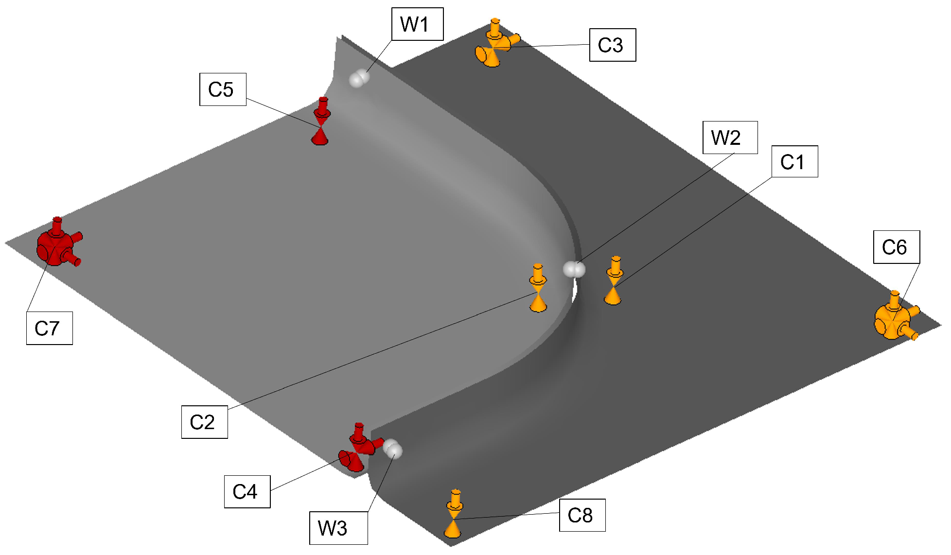
Assembly I consists of two sheet metal parts. Three weld points connect the parts together on the position of the curved flanges. The basic geometry of the base plate allows for understanding the clamping and welding sequence behavior. The clamping points and their initial order are shown in Figure 2 with the letter “C”. Initially, the two parts are placed in the fixture and clamped on eight points. The clamping points are only applied in the normal-to-surface direction. The in-plane arrows represent the locating mechanism in the fixture. The weld points and their initial numbering are shown with the letter “W”. The sheet thickness for both parts is 1.5 mm.

3.2. Assembly II

Assembly II, shown in Figure 3, has a more complex geometry with the surfaces changing in multiple dimensions. Similar to the previous assembly, the clamping points, the welding points, and their initial order are shown in Figure 3. Here, the sheet metal thickness on the lower part, with smaller dimensions, is 1.2 mm. The larger part has a sheet thickness of 1.6 mm. Initially, the parts are clamped in the fixture at six points. Later, eight weld points connect the parts together.
In the next section, the results of the clamping and welding sequence analysis and optimization are presented.

4. Results

The proposed method for the clamping sequence analysis and optimization considering non-nominal geometries is established for the digital twin and applied to the two reference assemblies. The following are presented in this section, according to the assembly steps.
  • Positioning the non-nominal parts in a rigid fixture.
  • Locking the in-plane translation and rotations.
  • Applying the clamping points in a sequence.
  • Capturing the weld relative displacements after clamping.
  • Optimizing the clamping sequence according to the objective above.
  • Performing spot welding with the optimal clamping sequence.
  • Optimizing the welding sequence with respect to the assembly displacements.
  • Releasing the assembly from the fixture and evaluating the assembly springback.
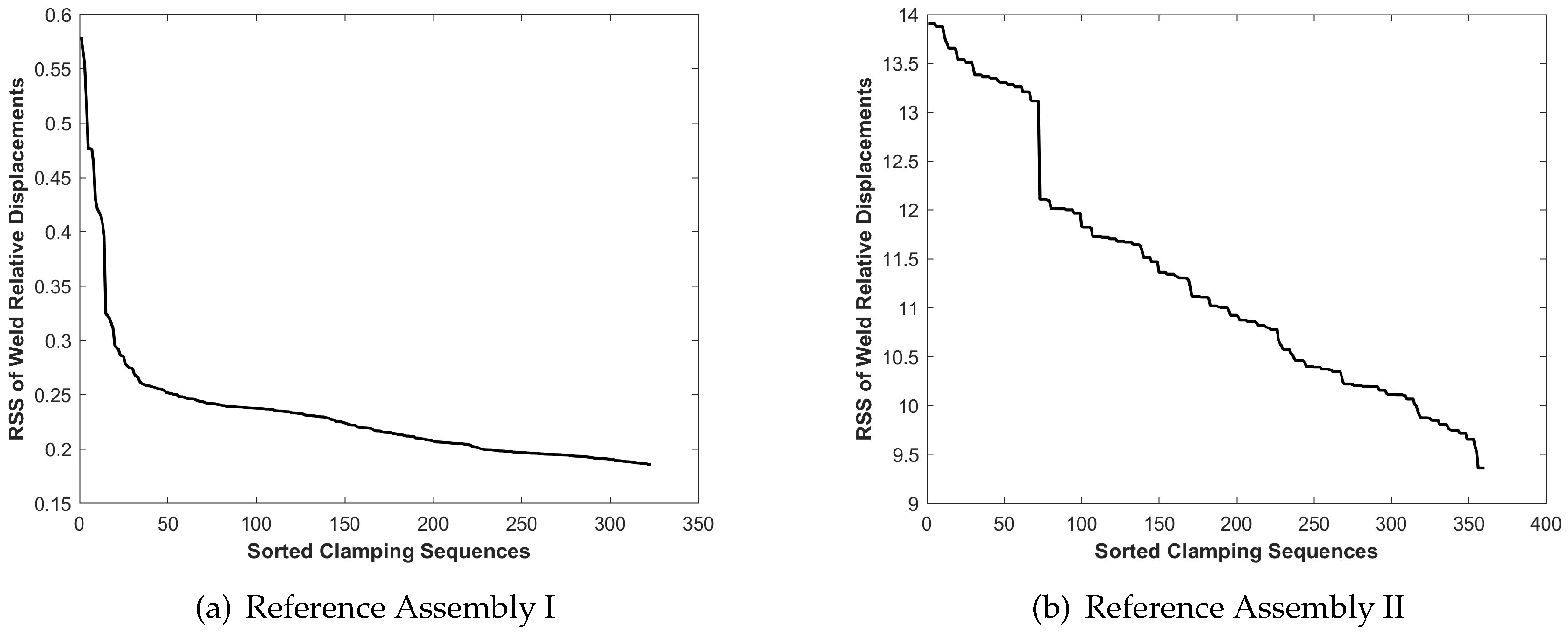
To visualize the impact of the clamping and welding sequence optimization, the results are presented while both the optimal and unideal (worst registered sequence) sequences are taken into consideration. Figure 4 is the optimization plot of the clamping sequence with respect to the weld relative displacements. The reference assemblies are held in the fixture, and the stepwise optimization process, Section 2.2, is applied to the assemblies. Table 1 presents the summary of the optimization process.
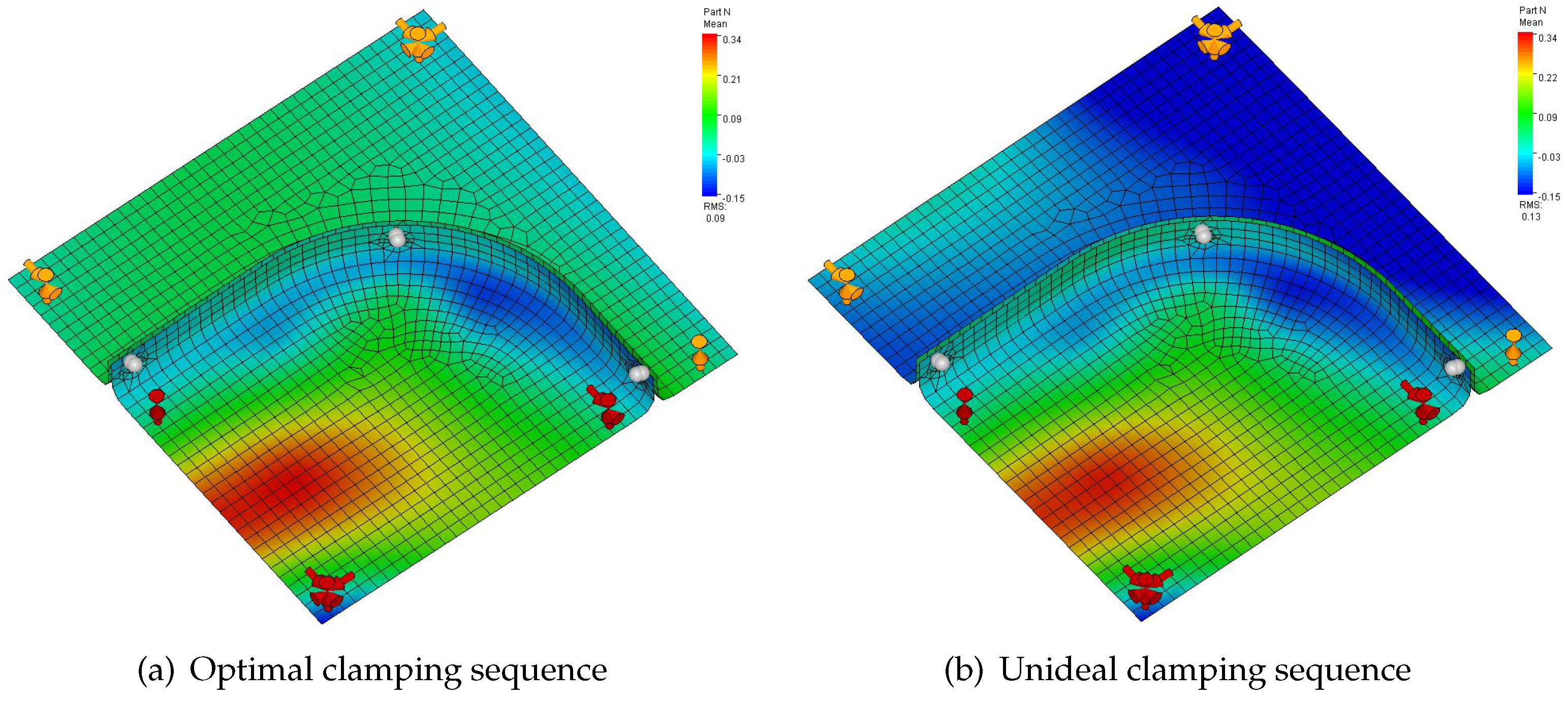
For Assembly I, the optimal clamping sequence of the eight included clamping points results in a weld relative displacement of 0.228 mm in the three weld points. An unideal clamping sequence results in 0.579 mm for this measure. The range of the differences in the weld relative displacements caused by the optimal and unideal clamping sequences is 1.5 times the optimal clamping sequence weld relative displacements, Figure 4a. This indicates the great impact of the clamping sequences on the follow-up welding step. After clamping, the assembly is welded with a sequence and then released from the fixture. The root mean square (RMS) of the nodal displacements of all the nodes in the assembly is considered for optimization of the assembly with respect to the welding sequences. Figure 5 visualizes the color plot of Assembly I after the welding and springback while it is welded with the welding sequence W1-W2-W3. This figure visualizes the impact of the clamping step on a predetermined welding sequence. In Figure 5a, the assembly is clamped with the optimal clamping sequence, Table 1. In Figure 5b, Assembly I is clamped with an unideal clamping sequence specified in Table 1.
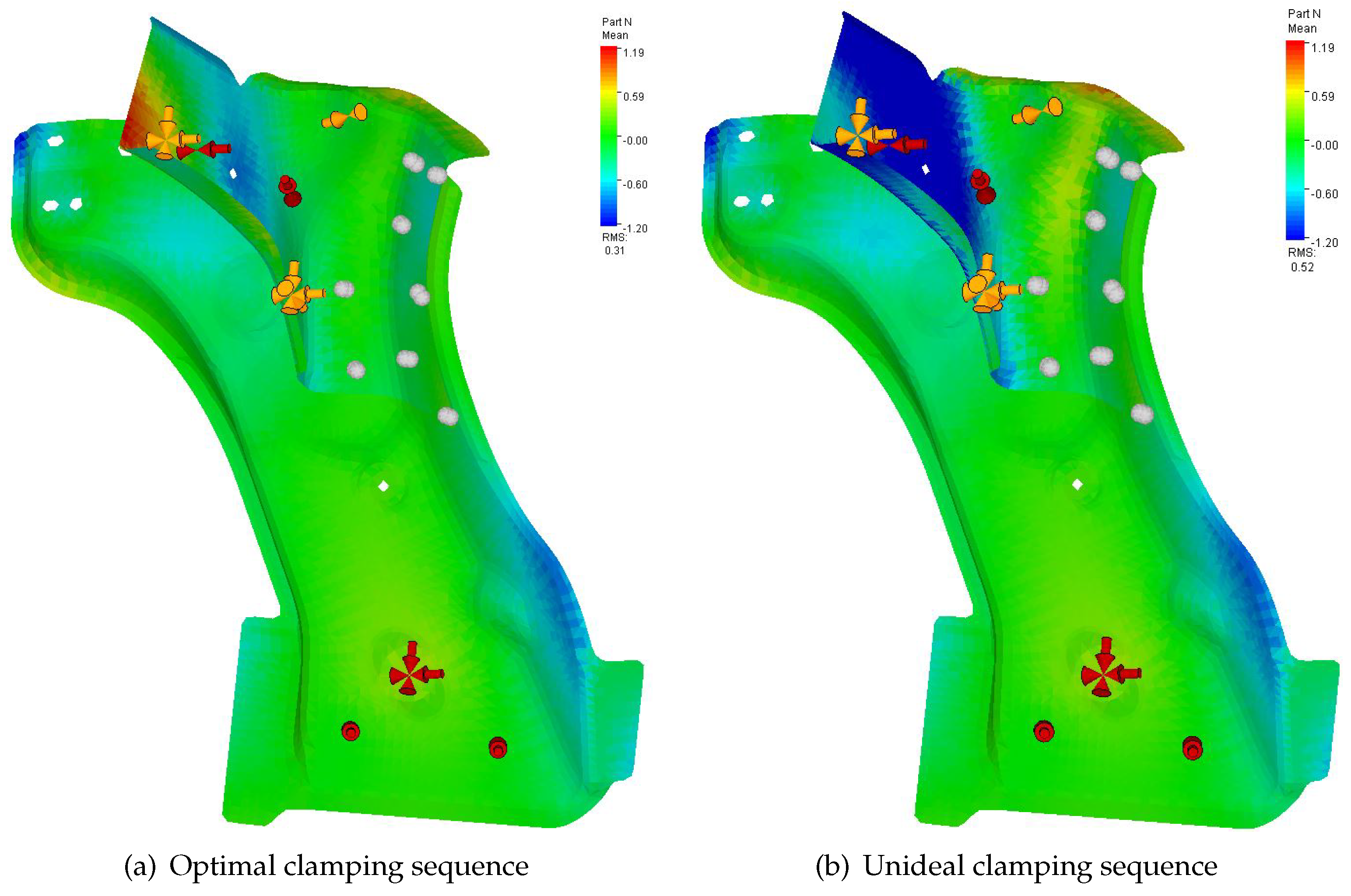
Similarly, for Assembly II, the clamping sequence is optimized. Six included clamping points are analyzed for the best clamping sequence, Figure 4b. The range of the differences in the weld relative displacements is 4.54 mm. The assembly is welded with the sequence W1-W2-W3-W4-W5-W6-W7-W8, and the color plot of the outcome of each clamping sequence is visualized in Figure 6. Figure 6a is Assembly II while it is clamped with the optimal clamping sequence, and Figure 6b is the color plot of Assembly II while it is clamped with an unideal clamping sequence, specified in Table 1, and welded with the sequence above.
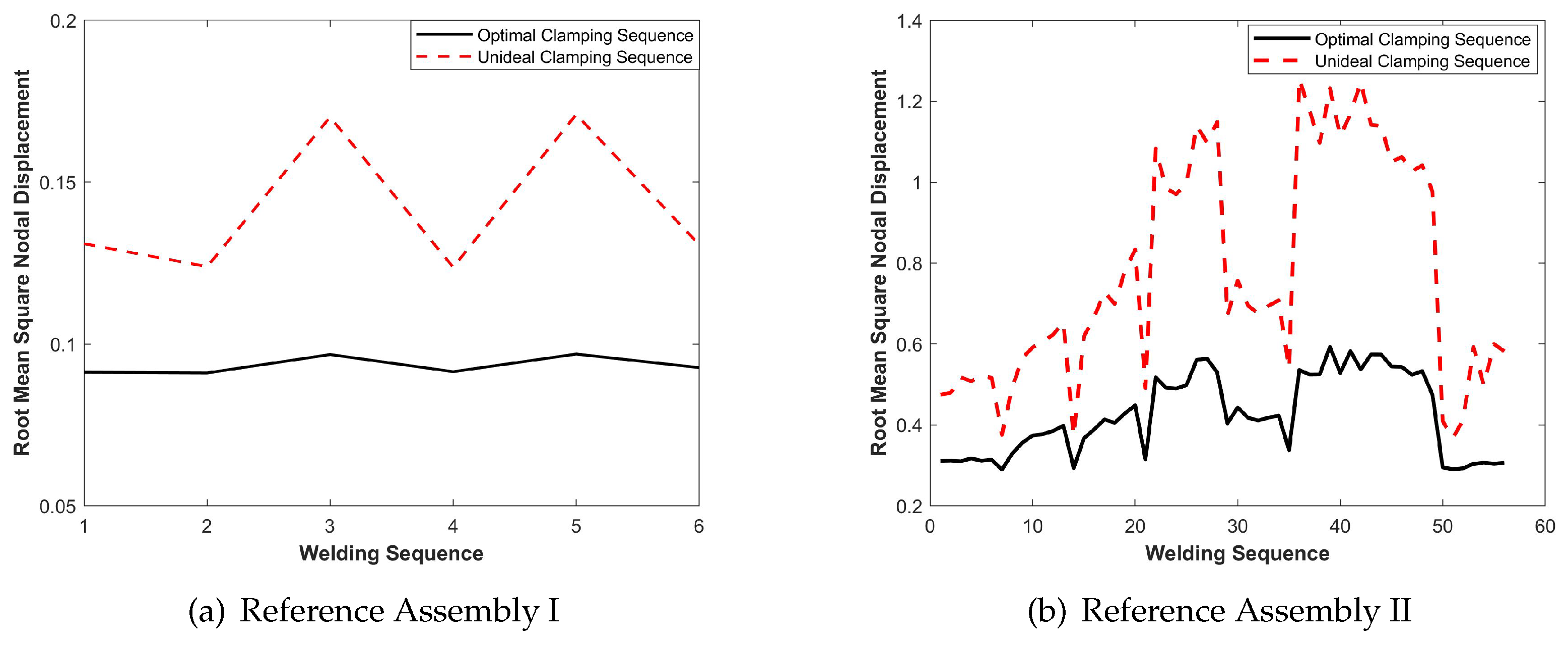
The welding sequence optimization is performed for the optimal and unideal clamping sequences. Figure 7a shows the welding sequence optimization steps on Assembly I with the optimal and unideal clamping sequences.The range of the displacements of this assembly after optimizing the welding sequences is 0.08 mm, which comprises 87% of the total optimal geometric deviation. The welding sequence optimization is also performed for Assembly II with the optimal and unideal clamping sequences. The optimization results are visualized in Figure 7b. The range of the differences in the displacements for this assembly with the optimal clamping and welding sequences and unideal clamping and welding sequences is 3.3 times the total optimal geometric deviation.

5. Discussion

A method for the modeling, simulation, and optimization of the clamping sequences is proposed for the geometry assurance digital twin, taking into account non-nominal part geometries. The proposed method is applied to two reference assemblies, and the geometric outcomes are analyzed and compared to unideal clamping sequences. The results show that the proposed objective of the weld relative displacement for the clamping sequence optimization establishes a better assembly condition for the follow-up welding step. This aspect can be explicitly seen in Figure 7, where the ranges of the displacements after welding in a sequence with an optimal clamping sequence are considerably lower for both assemblies compared to the unideal clamping sequences. Therefore, an optimal clamping sequence enhances the robustness of the assembly with respect to the geometric quality after welding in a sequence. In other words, the assembly with an optimal clamping sequence is less sensitive to the changes in the follow-up welding sequences in the assembly fixture.
Furthermore, the results show that clamping sequence optimization leads to reducing the geometric deviation of the assembly after welding and releasing the part from the fixture. Figure 5 and Figure 6 specifically visualize this improvement. For Assembly I, the clamping sequence optimization has resulted in a 31% reduction in the overall assembly deviation after springback, while similar welding conditions and sequences have been considered (from 0.13 to 0.09 mm). Similarly, for Assembly II, the assembly deviation after springback has reduced by 40% (from 0.52 to 0.31 mm). The results also show that the two-stage optimization of the clamping and welding sequences results in a reduction in the assembly deviation of 47% for Assembly I, Table 1. For Assembly II, this two-stage optimization results in a 77% reduction in the overall assembly deviation. Assembly II has a geometry that is more sensitive to the clamping sequences compared to Assembly I. For this reason, optimizing the clamping and welding sequences results in a more significant reduction in the overall assembly deviation.
Another discussion point is the physical interpretation for achieving the optimized geometric outcome. From this perspective, the clamping sequence can be achieved in an automatic assembly cell introducing delays in the locking mechanism at each clamping point. For adjusting the welding sequences, however, an automated assembly cell requires readjusting the robot arm program for welding in the defined sequences. Often, for changing the welding sequences, other constraints such as assembly lead time and robot path planning are also considered in the assembly cell, making the optimization more costly. Therefore, defining and optimizing the clamping sequences in the assembly cell is more cost-efficient, improving the geometric quality and increasing the assembly robustness to the follow-up welding operation.

6. Conclusions

The assembly process for non-rigid parts comprises four main steps: positioning the parts in the fixture, clamping, joining, and releasing the parts in the fixture. In this process, two of the operations, i.e., clamping and welding, involve a sequence of actions, where the parts are locked in different directions by applying forces on the positions of predefined points. Previous research has shown the impact of the welding and clamping steps on the overall assembly geometric outcome. Optimizing the sequence of operations is a combinatorial optimization problem, and physical experimentation is infeasible. In this paper, a method for the modeling, simulation, and optimization of the clamping sequences is introduced for the geometry assurance digital twin, Section 1.3 and Section 2. The interaction of the clamping step with the follow-up welding step is analyzed. The method is applied to two sheet metal assemblies, and the simulation and optimization results are compared with unideal clamping and welding sequence conditions. The results show that the clamping sequence optimization results in quality improvements by up to 31% in the assemblies. Furthermore, it has been shown that an optimal clamping sequence condition results in a more robust assembly for the follow-up welding step. The results also reveal that combining the welding and joining sequence optimization results in an up to 77% quality improvement in the welded assemblies compared to the unideal clamping and welding sequence.
Future research includes further applying the proposed method to problems with a large number of clamping and welding points. Furthermore, the proposed clamping sequence optimization method can be combined with the clamping position optimization method to enhance the accuracy of the simulation representation in fixture design. This aspect can be integrated into fixture layout optimization considering the position and the sequence of the clamping conditions. The proposed method enables the implementation of the clamping sequence analysis and optimization of the software platforms used for geometry assurance of the sheet metal assemblies during the concept and prototyping phases. The sequence of the clamping operation is a necessary aspect for the simulation of the geometric outcome of the welded assemblies, as exact simultaneity in performing the operation is not physically achievable.

Author Contributions

Conceptualization, R.S.T.; methodology, R.S.T., H.Z. and F.L.; software, R.S.T. and L.L.; validation, R.S.T., H.Z., F.L. and L.L.; formal analysis, R.S.T., H.Z. and F.L.; investigation, R.S.T. and H.Z.; resources, R.S.T. and H.Z.; data curation, R.S.T.; writing—original draft preparation, R.S.T. and H.Z.; writing—review and editing, R.S.T., H.Z., F.L., K.P.-B., K.W. and R.S.; visualization, R.S.T. and H.Z.; project administration, R.S.T., H.Z., F.L., K.P.-B., K.W. and R.S.; funding acquisition, K.W. and R.S. All authors have read and agreed to the published version of the manuscript.

Funding

This research was funded by the Swedish Innovation Agency, Vinnova, Project Digital Quality Assurance for Sustainable Industry, Digi-Q.

Institutional Review Board Statement

Not applicable.

Informed Consent Statement

Not applicable.

Data Availability Statement

The data presented in this study are available on request from the corresponding author. The data are not publicly available due to privacy.

Acknowledgments

This work was carried out at the Wingquist Laboratory within the Area of Advance Production at Chalmers and supported by the priority area Sustainable Industry at the Swedish Innovation Agency (VINNOVA). The support is gratefully acknowledged.

Conflicts of Interest

Authors Hanchen Zheng and Frank Litwa were employed by the company Mercedes-Benz AG. The remaining authors declare that the research was conducted in the absence of any commercial or financial relationships that could be construed as a potential conflict of interest.

References

  1. Hu, M.; Lin, Z.; Lai, X.; Ni, J. Simulation and analysis of assembly processes considering compliant, non-ideal parts and tooling variations. Int. J. Mach. Tools Manuf. 2001, 41, 2233–2243. [Google Scholar] [CrossRef]
  2. Shen, Z.; Ameta, G.; Shah, J.J.; Davidson, J.K. A Comparative Study of Tolerance Analysis Methods. J. Comput. Inf. Sci. Eng. 2005, 5, 247–256. [Google Scholar] [CrossRef]
  3. RD&T Technology. Robust Design and Tolerancing Software RD&T. 2023. Available online: https://www.rdnt.se/ (accessed on 5 October 2023).
  4. 3DSC. Dimensional Control System 3DCS. 2023. Available online: https://www.3dcs.com/ (accessed on 5 October 2023).
  5. Liu, S.C.; Hu, S.J. Variation simulation for deformable sheet metal assemblies using finite element methods. J. Manuf. Sci. Eng. 1997, 119, 368–374. [Google Scholar] [CrossRef]
  6. Chang, M.; Gossard, D. Modeling the assembly of compliant, non-ideal parts. Comput.-Aided Des. 1997, 29, 701–708. [Google Scholar] [CrossRef]
  7. Camelio, J.; Hu, S.J.; Ceglarek, D. Modeling variation propagation of multi-station assembly systems with compliant parts. J. Mech. Des. 2003, 125, 673–681. [Google Scholar] [CrossRef]
  8. Anwer, N.; Ballu, A.; Mathieu, L. The skin model, a comprehensive geometric model for engineering design. Cirp Ann. 2013, 62, 143–146. [Google Scholar] [CrossRef]
  9. Cai, W.; Hu, S.J.; Yuan, J.X. A Variational Method of Robust Fixture Configuration Design for 3-D Workpieces. J. Manuf. Sci. Eng. 1997, 119, 593–602. [Google Scholar] [CrossRef]
  10. Maropoulos, P.G.; Vichare, P.; Martin, O.; Muelaner, J.; Summers, M.; Kayani, A. Early design verification of complex assembly variability using a Hybrid–Model Based and Physical Testing–Methodology. Cirp Ann. 2011, 60, 207–210. [Google Scholar] [CrossRef]
  11. Yao, S.; Luan, Y.; Ceccarelli, M.; Carbone, G. Optimization Method of the Clamping Force for Large Cabin Parts. Appl. Sci. 2023, 13, 12575. [Google Scholar] [CrossRef]
  12. Raghu, A.; Melkote, S.N. Analysis of the effects of fixture clamping sequence on part location errors. Int. J. Mach. Tools Manuf. 2004, 44, 373–382. [Google Scholar] [CrossRef]
  13. Li, B.; Melkote, S.N. Improved workpiece location accuracy through fixture layout optimization. Int. J. Mach. Tools Manuf. 1999, 39, 871–883. [Google Scholar] [CrossRef]
  14. Matuszyk, T.; Cardew-Hall, M.; Rolfe, B. The effect of clamping sequence on dimensional variability in sheet metal assembly. Virtual Phys. Prototyp. 2007, 2, 161–171. [Google Scholar] [CrossRef]
  15. Tabar, R.S.; Lorin, S.; Cromvik, C.; Lindkvist, L.; Wärmefjord, K.; Söderberg, R. Efficient spot welding sequence simulation in compliant variation simulation. J. Manuf. Sci. Eng. 2021, 143, 071009. [Google Scholar] [CrossRef]
  16. Choi, W.; Chung, H. Variation simulation of compliant metal plate assemblies considering welding distortion. J. Manuf. Sci. Eng. 2015, 137. [Google Scholar] [CrossRef]
  17. Zheng, H.; Litwa, F.; Bohn, M.; Paetzold, K. Tolerance optimization for sheet metal parts based on joining simulation. Procedia Cirp 2021, 100, 583–588. [Google Scholar] [CrossRef]
  18. Moos, S.; Vezzetti, E. Compliant assembly tolerance analysis: Guidelines to formalize the resistance spot welding plasticity effects. Int. J. Adv. Manuf. Technol. 2012, 61, 503–518. [Google Scholar] [CrossRef]
  19. Tabar, R.S.; Lindkvist, L.; Wärmefjord, K.; Söderberg, R. Efficient joining sequence variation analysis of stochastic batch assemblies. J. Comput. Inf. Sci. Eng. 2022, 22, 040905. [Google Scholar] [CrossRef]
  20. Lu, C.; Zhao, H.W. Fixture layout optimization for deformable sheet metal workpiece. Int. J. Adv. Manuf. Technol. 2015, 78, 85–98. [Google Scholar] [CrossRef]
  21. Qin, G.; Zhang, W.; Wan, M. Analysis and Optimal Design of Fixture Clamping Sequence. J. Manuf. Sci. Eng. 2005, 128, 482–493. [Google Scholar] [CrossRef]
  22. Yu, H.; Xu, X.; Zheng, B.; Lai, X. Welding-induced buckling prediction for large thin-walled cylindrical structures with non-uniform stress fields by friction stir welding. Int. J. Adv. Manuf. Technol. 2019, 103, 4635–4647. [Google Scholar] [CrossRef]
  23. Xie, L.S.; Hsieh, C. Clamping and welding sequence optimisation for minimising cycle time and assembly deformation. Int. J. Mater. Prod. Technol. 2002, 17, 389–399. [Google Scholar] [CrossRef]
  24. Wu, Y.; Gao, S.; Chen, Z. Automated modular fixture planning based on linkage mechanism theory. Robot.-Comput.-Integr. Manuf. 2008, 24, 38–49. [Google Scholar] [CrossRef]
  25. Wu, Y.; Rong, Y.; Ma, W.; LeClair, S.R. Automated modular fixture planning: Accuracy, clamping, and accessibility analyses. Robot.-Comput.-Integr. Manuf. 1998, 14, 17–26. [Google Scholar] [CrossRef]
  26. Jeng, S.L.; Chen, L.G.; Chieng, W.H. Analysis of minimum clamping force. Int. J. Mach. Tools Manuf. 1995, 35, 1213–1224. [Google Scholar] [CrossRef]
  27. Hajimiri, H.; Abedini, V.; Shakeri, M.; Siahmargoei, M.H. Simultaneous fixturing layout and sequence optimization based on genetic algorithm and finite element method. Int. J. Adv. Manuf. Technol. 2018, 97, 3191–3204. [Google Scholar] [CrossRef]
  28. Schenk, T.; Richardson, I.; Kraska, M.; Ohnimus, S. A study on the influence of clamping on welding distortion. Comput. Mater. Sci. 2009, 45, 999–1005. [Google Scholar] [CrossRef]
  29. Gonzalo, O.; Seara, J.M.; Guruceta, E.; Izpizua, A.; Esparta, M.; Zamakona, I.; Uterga, N.; Aranburu, A.; Thoelen, J. A method to minimize the workpiece deformation using a concept of intelligent fixture. Robot.-Comput.-Integr. Manuf. 2017, 48, 209–218. [Google Scholar] [CrossRef]
  30. Grieves, M.; Vickers, J. Digital twin: Mitigating unpredictable, undesirable emergent behavior in complex systems. In Transdisciplinary Perspectives on Complex Systems; Springer: Berlin/Heidelberg, Germany, 2017; pp. 85–113. [Google Scholar]
  31. Schleich, B.; Anwer, N.; Mathieu, L.; Wartzack, S. Shaping the digital twin for design and production engineering. Cirp Ann. 2017, 66, 141–144. [Google Scholar] [CrossRef]
  32. Franciosa, P.; Sokolov, M.; Sinha, S.; Sun, T.; Ceglarek, D. Deep learning enhanced digital twin for Closed-Loop In-Process quality improvement. Cirp Ann. 2020, 69, 369–372. [Google Scholar] [CrossRef]
  33. Polini, W.; Corrado, A. Digital twin of composite assembly manufacturing process. Int. J. Prod. Res. 2020, 58, 5238–5252. [Google Scholar] [CrossRef]
  34. Söderberg, R.; Wärmefjord, K.; Carlson, J.S.; Lindkvist, L. Toward a Digital Twin for real-time geometry assurance in individualized production. Cirp Ann. 2017, 66, 137–140. [Google Scholar] [CrossRef]
  35. Tabar, R.S.; Wärmefjord, K.; Söderberg, R. Optimal part matching and joining sequence in non-rigid assemblies for improved geometric quality. Procedia CIRP 2022, 78, 421–426. [Google Scholar] [CrossRef]
  36. Aderiani, A.R.; Wärmefjord, K.; Söderberg, R. Evaluating different strategies to achieve the highest geometric quality in self-adjusting smart assembly lines. Robot.-Comput.-Integr. Manuf. 2021, 71, 102164. [Google Scholar] [CrossRef]
  37. Tabar, R.S.; Wärmefjord, K.; Söderberg, R.; Lindkvist, L. Critical joint identification for efficient sequencing. J. Intell. Manuf. 2021, 32, 769–780. [Google Scholar]
  38. Tabar, R.S.; Wärmefjord, K.; Söderberg, R. Rapid sequence optimization of spot welds for improved geometrical quality using a novel stepwise algorithm. Eng. Optim. 2021, 53, 867–884. [Google Scholar] [CrossRef]
  39. Nocedal, J.; Wright, S.J. Numerical Optimization; Springer: Berlin/Heidelberg, Germany, 1999. [Google Scholar]
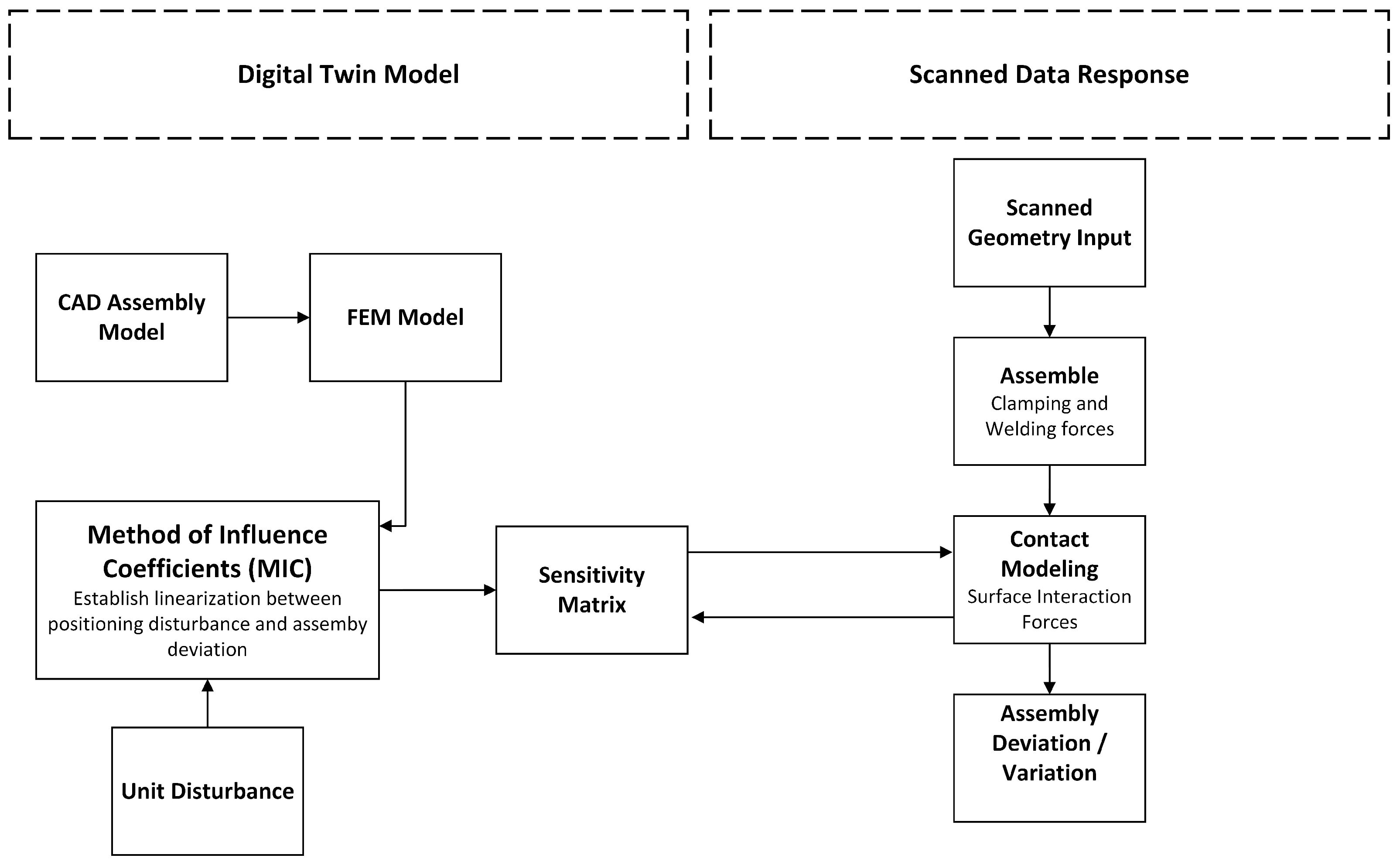
Figure 1. Overview of the assembly digital twin model.
Applsci 14 00510 g001
Figure 2. Reference Assembly I.
Applsci 14 00510 g002
Figure 3. Reference Assembly II.
Applsci 14 00510 g003
Figure 4. Clamping sequence optimization of the two reference assemblies.
Applsci 14 00510 g004
Figure 5. Reference Assembly I welded with optimal and unideal clamping sequences.
Applsci 14 00510 g005
Figure 6. Reference Assembly II welded with optimal and unideal clamping sequences.
Applsci 14 00510 g006
Figure 7. Comparison of the welding sequence optimization performed with optimal clamping and unideal clamping sequences.
Applsci 14 00510 g007
Table 1. Sequence optimization results.
Assembly IClamping StepWeld Relative Disp.Welding StepNodal Disp.
SequenceRSS (mm)SequenceRMS (mm)
OptimalC8-C5-C1-C3-C4-C7-C2-C60.228W1-W3-W20.091
UnidealC3-C8-C7-C4-C6-C2-C5-C10.579W3-W1-W20.171
Assembly II
OptimalC2-C3-C4-C6-C5-C19.364W8-W1-W7-W6-W5-W4-W3-W20.290
UnidealC6-C2-C4-C5-C3-C113.903W3-W8-W7-W6-W5-W4-W2-W11.255
Disclaimer/Publisher’s Note: The statements, opinions and data contained in all publications are solely those of the individual author(s) and contributor(s) and not of MDPI and/or the editor(s). MDPI and/or the editor(s) disclaim responsibility for any injury to people or property resulting from any ideas, methods, instructions or products referred to in the content.