Abstract
Horses have been companions of people for thousands of years. Areas in which humans use these animals include, for example, transport, participation in sports competitions, or during rehabilitation (hippotherapy). Unfortunately, injuries such as lower limb fracture very often require euthanasia due to the significant difficulties in conducting fracture therapy/repair. Therefore, there are still many possibilities for the improvement of existing treatments. The aim of the study was to conduct a numerical analysis enabling the prediction of bone union of the third metacarpal bone of a horse. The loading conditions and type of fracture were based on a pony weighing 120 kg; however, research on a live animal was not the purpose of this study. Numerical studies were carried out for three different methods of stabilization using bone plates in the Ansys program (lateral, anterior, and lateral–anterior stabilization). An algorithm based on the Carter model was used to predict bone union, while linear-coupled models were used to describe the behaviour of materials. The authors also performed dynamic analyses in the Abaqus/Explicit program to determine the maximum speed at which the horse could move so that the fracture would not deepen. For dynamic analyses, the authors used nonlinear models—Johnson–Cook in the case of the 316L surgical steel material and cortical bone. Material failure was described using the Johnson–Cook failure model for steel and the limit strain model for cortical bone. A series of numerical simulations allowed to determine the direction of bone union building, and the most favourable case of stabilization was determined.
1. Introduction
Bone tissue is a dynamic structure that protects internal organs and is a rigid segment that allows the transfer of forces, among others. during locomotion. It is a living tissue whose mineralized structure covers two thirds of the bone’s dry weight. There are three regions in horse bones: the body, the epiphysis, and the metaphysis. The diaphysis consists of cortical bone, while the epiphysis and metaphysis contain trabecular cancellous bone. The body contains bone marrow, initially red, which, over time, becomes yellow marrow. The bones are covered with periosteum, which changes as the horse ages, becoming thinner and less adherent to the bones. At the microstructural level, the basic unit of bone is the osteon, consisting of a Haversian canal surrounded by laminae of mineralized bone. There are three types of cells in bones: osteocytes, osteoblasts and osteoclasts. Osteoblasts, the bone-forming cells, produce most of the components of the organic bone matrix, including collagen. Osteocytes, derived from osteoblasts, maintain intercellular communication. Osteoclasts, osteoclastic cells, are responsible for bone resorption. The organic matrix of bone contains mainly collagen, and the inorganic part is mainly dihydroxyapatite, which gives the bone hardness [1].
Horse bone is a natural composite of two main components: collagen fibres (matrix) and a mineral part (reinforcement). Its trabecular structure makes it light yet highly durable, with mechanical properties oriented according to external loads. Cancellous bone is more plastic and has greater elasticity than cortical bone. The mechanical properties of bones are anisotropic, which means that they depend on the direction of force. Figure 1 shows possible bone loading conditions that may occur in a horse’s long bones. Research shows large differences in bone strength, depending on, among others, age, bone density, and tissue type. The Young’s modulus of horse bone is 15 to 24 GPa for cortical bone and 0.12 to 0.59 GPa for cancellous bone, and the Poisson’s ratio is approximately 0.3 for both types of tissue [2]. Depending on the stress conditions occurring on the bones, different types of fractures will occur, which may vary in terms of the complexity of subsequent treatment (Figure 1 and Figure 2).
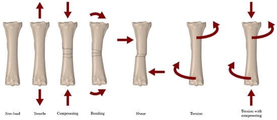
Figure 1.
Possible bone stress conditions that may occur in the horse’s long bones [3].
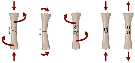
Figure 2.
Possible types of fractures depending on the type of load [3].
The stabilization of third metacarpal bone fractures in horses is an important area of interest in orthopaedic veterinary medicine, which is crucial for the animal’s return to full fitness. These fractures are a common condition among horses and may result from intense training, accidents, or natural degenerative processes. The effectiveness of treatment and the prognosis of recovery of the horse’s motor function after a fracture depend largely on the appropriate stabilization of the broken bone and the body’s ability to heal the bones [4,5].
Numerical analysis, using advanced computer modelling methods, has become an indispensable tool in the diagnosis and treatment of fractures of the third metacarpal bone in horses. By precisely simulating the movement dynamics and mechanical loads, researchers can better understand the behaviour of broken bones in various conditions and assess the effectiveness of various stabilization methods.
In 2007, the Journal of the American Veterinary Medical Association presented a scientific report on retrospective research in which external stabilization in the form of transfixation casting was used for a group of 29 adult horses and 8 foals with fractures of the third metacarpal or metatarsal bone. This method involves inserting transosseous pins proximally to the fracture site and placing it in a plaster cast for 45 days. To allow movement during treatment, the cast was constructed using plaster of Paris with the addition of fibreglass, Steinmann pins, and a metal walking frame. It is recommended to use up to three 6.35 mm transfixation pins in the third metacarpal and metatarsal bones of adult horses, the application of which is a difficult process and includes, among others: drilling a hole and then tapping the bone surface. As a result of the study, it was reported that some individuals developed osteomyelitis and failure of repair, or communited bone fractures during recovery from anaesthesia. Complications directly related to the transfixation pins included fracture through the pin hole in 5 adult horses. The results of this study showed that immobilization casting can be an effective method of treating third metacarpal or metatarsal fractures with an overall success rate of 77%. Despite a good overall success rate, secondary pinhole fractures are a significant complication of transfixation casting [6].
The Swiss research institute, using the ABAQUS 6.13/CAE software, carried out a finite element analysis of the pin-sleeve system for the external stabilization of distal limb fractures in horses, which, in its nature, resembles the system discussed above, in addition to the plaster system with a stem sleeve that is inserted into the bone. A study using numerical simulations compared the mechanical performance of a traditional pin system (transfixation pin cast—TPC) with the performance of the proposed pin-sleeve cast system (PSC). The bone models were obtained based on previously tested in vitro bone substitutes. The use of PSC significantly reduced the peak strain in the pin area and evenly distributed the stresses in the bone cortex. Both PSC and TPC induced similar proximal fragment displacement and had similar stress concentrations around bone defects during the implant removal procedure. These results demonstrate the effectiveness of the PSC load-bearing mechanism in the context of the treatment of equine limb fractures [7].
A different approach was presented by a group of veterinarians from California, where the MP35N-stabilized intramedullary nailing system was used to treat third metacarpal fractures in adult horses. Twenty-four pairs of equine cadavers of the metacarpal bones were used. Part of the bone was subjected to gap ostectomy and then stabilized using a 4-hole MP35N intramedullary nail with a diameter of 14 mm and a length of 250 mm and four MP35N locking screws with a diameter of 7 mm and a length of 60 mm. Mechanical tests were carried out for the samples prepared in this way, including: compression, four-point bending, and torsion to assess the biomechanical properties of the treatment system. It was found that the in vitro mechanical properties of the third metacarpal bone osteotomized using the MP35N system were much lower than those obtained from undamaged samples, but were higher than the estimated in vivo loads for horses during post-operative rehabilitation. The removal of the osteochondral core was an effective method of gaining access to the medullary canal of the third metacarpal bone. This technique allowed the insertion of the nail from a place distant from the fracture without disturbing the surrounding soft tissue support structures, but is probably associated with the development of a secondary disease of the middle wrist joint or arthritis [8].
The aim of the study was to assess the possibility of bone union of the third metacarpal bone of a horse, surgically connected with a stabilizing plate and bone screws in several variants of stabilization in a computational environment. For this purpose, a series of numerical calculations were performed to indicate the maximum force at which the implant–bone system will remain stable. The loading conditions and type of fracture were based on the bone fracture of a pony weighing 120 kg; however, no living animal was used to conduct the simulation. Through the analysis of the latest scientific research, various therapeutic approaches and their effectiveness in the context of restoring full functionality of the limb are discussed. A novelty in the work was the development of an algorithm based on Carter’s model, which allowed for the prediction of bone remodelling in the fracture area.
Considerations regarding the stabilization of third metacarpal fractures in horses have important practical implications for veterinarians and horse owners. Understanding the processes of healing a broken bone and assessing the effectiveness of various stabilization methods are crucial for making accurate therapeutic decisions and achieving optimal clinical results.
2. Description of Problem
Horses have been kept by people for thousands of years as, among others, a means of communication and agricultural machinery. Over time, they also became part of the world of sports and entertainment, when disciplines such as horse racing, dressage, and jumping were created. Nowadays, horse riding is also considered recreation and can even be therapy. Hippotherapy is a form of multi-profile rehabilitation used in the case of, for example, neurological and orthopaedic disorders, affecting both the patients’ motor skills and their mental and neurological condition [9,10].
Despite a very close relationship with humans, a serious limb injury in a horse most often results in the animal’s euthanasia [11]. Treating fractures in horses is much more difficult than in humans. The reason is not only the weight of the animal, but also the lack of covering and stabilization of the bones by a thick layer of soft tissue. Only ligaments are attached to the horse’s third metacarpal bone and it is covered with a thin layer of skin [12,13].
A horse bone fracture is a biomechanical response to various loads such as tension, compression, bending, torsion, and combinations thereof. The shape of the fracture depends on the direction of force—it may be a transverse, oblique, spiral fracture, etc. There are also low-energy fractures (e.g., during a walk) and high-energy fractures (e.g., as a result of an impact). They may also be open (with soft tissue damage) or closed. The diagnosis of a fracture often requires imaging tests and the observation of clinical symptoms. One of the main factors in the success of bone union treatment is the time that has passed from the injury to stabilization and to allowing the animal to unload the leg. The lack of quick stabilization carries a high risk of significant aggravation of the injury, including the formation of an open fracture with displacement. Such injuries have a low success rate when treated with traditional, non-surgical methods [14,15].
The process of healing bone fractures is a complex repair mechanism that occurs in response to injury. The bone has the ability to completely regenerate, restoring its original structure without leaving scars or defects. There are two main types of fracture healing: primary (direct) and secondary [16].
Primary healing occurs when bone fragments are close together or there is direct contact between them. Secondary healing, more complex, consists of three phases: inflammation, repair, and remodelling. This process usually leads to bone fusion naturally. Figure 3 shows examples of the stages of bone union formation [17,18].
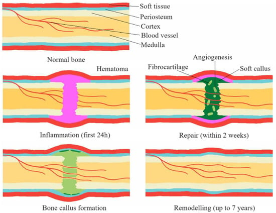
Figure 3.
Stages of the bone union process [17].
A bone fracture initiates not only the process of repairing the bone tissue itself, but also damages the periosteum and endosteum, which is a stimulus for repair. This process involves a number of complex biochemical and biomechanical interactions in which cytokines, mesenchymal stem cells, and the regulation of angiogenic processes play a key role. This results in the activation of repair processes, including the process of creating inflammation, which is crucial for the initiation of healing [19,20].
The remodelling phase, the final stage of the healing process, is characterized by the gradual resorption of calcified callus and the simultaneous formation of new bone tissue. This process is regulated by numerous factors, such as growth hormones, growth factors, and cytokines. Ultimately, this leads to the restoration of bone structure and function to its original state [21,22].
Treating fractures in horses is a significant challenge due to, for example, the potential complications during the healing process. The inability to provide the animal with recommendations regarding immobilization or rehabilitation means that even the most advanced techniques may encounter difficulties. In the case of limb fractures in horses, complications during bone union, such as infections, problems with stabilization, and delays in union, are quite common [23,24].
Factors that may contribute to a delayed union include initial or post-traumatic infections, improper bone fixation, or soft tissue disruption. Although long bone fractures in horses tend to heal within 3–4 months, establishing an exact timeline for the healing process is difficult. Individual differences in the rate of healing and natural individual changes in the process of bone union make it difficult to clearly diagnose delays. Excessive loads on the limb may lead to damage to the fusion, while excessive stiffness of immobilization may stop the healing process. Optimal load transfer and appropriate bone deformations play a key role in the successful completion of the process of fusion of bone fragments in horses [14,15,25].
The forelimb, also called the thoracic limb, is connected to the horse’s spine through the shoulder girdle, formed only by the shoulder blade and supported by a large group of muscles, tendons, and fascia of the shoulder girdle. This is important because the forelimbs bear 60% of the horse’s body weight when at rest and absorb most of the energy when the horse is jumping [26]. The structure of the forelimb includes 10 bones and 5 joints. Figure 4 shows the structure of the horse’s forelimb.
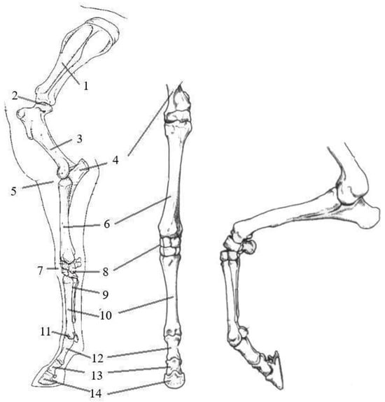
Figure 4.
Bones of the horse’s forelimb: 1—scapula; 2—shoulder joint; 3—humerus; 4—ulna bone; 5—elbow joint; 6—radius bone; 7—carpal joint; 8—carpal bones; 9—splint bones; 10—third metacarpal bone; 11—fetlock joint and sesamoid bone; 12—proximal phalanx; 13—middle phalanx; 14—distal phalanx [26,27].
The third metacarpal bone (MC III) is a component of the front limbs. The small carpal and metacarpal bones fused with them (MC II and IV), often called splint or vestigial bones, perform important functions. In young horses, they are connected to the third metacarpal bone through the interosseous ligament, which, with age, is replaced by bone, sometimes completely fused. Metacarpals I and V are completely absent in horses. The second metacarpal bone is a medial bone that plays an important role in load-bearing. In turn, the fourth metacarpal bone, which is a lateral bone, is the attachment point for ligaments. These bones are approximately one-third shorter than the third metacarpal bone [26].
The MC III is strong and well-developed because it must be able to support the entire weight carried by the limb. The proximal end of the third metacarpal bone, on the wrist side, has articular surfaces occurring at the place where the splint bones connect with the third metacarpal bone. The proximal section of the third metacarpal bone also has a metacarpal tuberosity located on its dorsomedial surface. The distal end of the bone has an articular surface consisting of two condylar regions that are separated by the sagittal crest. Figure 5 shows the metacarpal bone of the thoracic limb from the palmar, dorsal, and lateral sides.
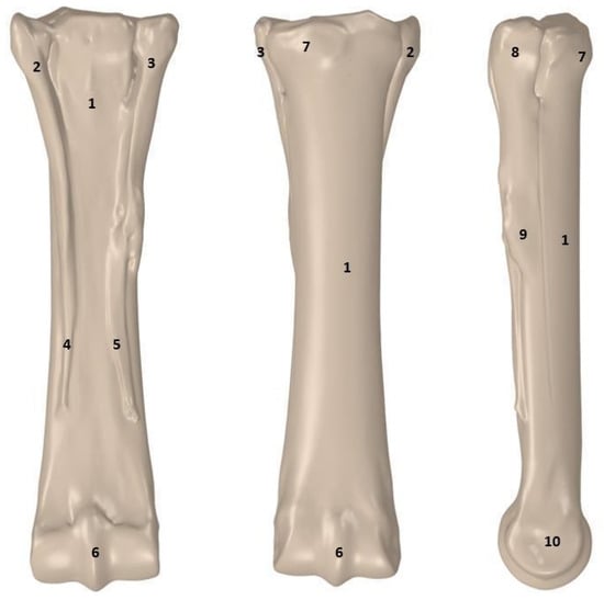
Figure 5.
Metacarpal bones of the thoracic limb in three views: 1—body of the 3rd metacarpal bone; 2—lateral splint head; 3—medial splint head; 4—distal end of the 4th metacarpal bone; 5—distal end of the 2nd metacarpal bone; 6—sagittal ridge; 7—metacarpal tuberosity; 8—head of the 2nd metacarpal bone; 9—body of the 2nd metacarpal bone; 10—medial collateral fossa [26].
3. Materials and Methods
3.1. Preparation of a Numerical Model
The bone model came from an adult horse from the Wrocław University of Environmental and Life Sciences teaching materials; therefore, no animals were harmed for the purposes of creating this article (Figure 6); the bone length was 280 mm while the pony’s third metacarpal is proportionately smaller due to its size. The length of the modelled bone was 148 mm, so the model was scaled.
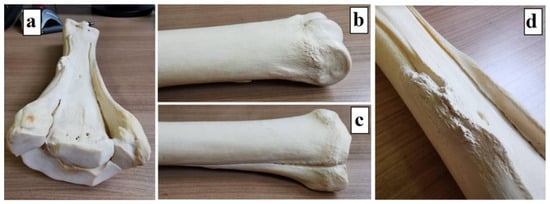
Figure 6.
Third metacarpal bone model: (a) left third metacarpal bone of an adult horse; (b) distal end; (c) proximal end; and (d) the body with splint bones.
The next step was to perform a 3D scan of the supplied material and scale it to the dimensions described earlier. This allowed us to obtain two models in .stl format, trabecular bone and cortical bone. The basis for the creation of the model is composite X-ray images of the specimen taken from different directions; .stl format saves three-dimensional objects in the form of a mesh. As a result of this, a computer model was obtained with dimensions corresponding to the actual dimensions of the pony (Figure 7a). The model was cleaned of artifacts, so it consisted of the main part of cortical bone and 4 trabecular bone elements. Then, a crack was created throughout the entire volume of the bone (Figure 7b).
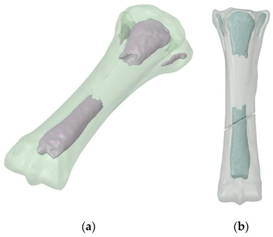
Figure 7.
3D bone model: (a) no fracture; and (b) after fracture formation.
Then, the model was imported into the Ansys and ABAQUS/Explicit computing environments. Stabilization models were prepared—anterior, lateral, and anterolateral. Example models in the ABAQUS program are presented below (Figure 8).
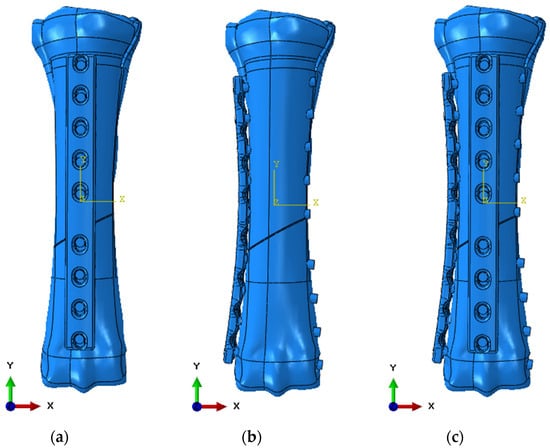
Figure 8.
Numerical model in ABAQUS 6.13 software: (a) anterior stabilization; (b) lateral stabilization; and (c) anterolateral stabilization.
The geometric model used in static calculations in the Ansys Workbench 2024 R1 environment was divided using 10-node elements of a higher order. Static tests were carried out in the Ansys program in order to initially determine the stresses and displacements of the structure. The load values were 353 N for a horse standing still, 483 N for a horse moving at a speed of 2.5 km/h, and 2400 N for a horse moving at a speed of 5.0 km/h. The adopted values come from studies included in sources [27,28], in which the authors calculated the N/kg value depending on the animal’s movement speed. The model mesh has been refined in the areas of implant–bone contact, bone–screw contact, and implant–screw contact areas. The model assumed that the contact connections between bone screws and bone and between screws and bone plates are of the bonded type. Contacts between the bone plate and the bone surface were defined as frictional with a friction coefficient of 0.38 [29]. The model also generated the volume of bone scar in the form of a solid sphere, which was placed symmetrically between the bone fragments. The contact connection between the scar and the fragments was modelled as a bonded type contact. The connection between the bone scar and the implant was omitted. Fixing the implant was achieved by removing all degrees of freedom on the articular surface belonging to the distal end of the bone (Figure 9). The load in the form of nodal forces with specific values and directions of action was applied to the articular surfaces of the proximal end. As a result of the calculations, the distributions of reduced stresses and main stresses 1 and 3 in the volume of the bone and implant were obtained. Nodal displacements on the surfaces in contact with bone fragments were recorded in the volume of the bone scar. These displacements were then mapped onto an isolated bone scar model, in which changes in the density distribution depending on the type of stabilization were predicted using a program based on Carter’s algorithm [30].
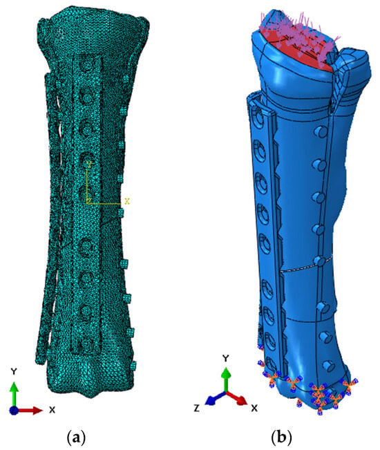
Figure 9.
Numerical model in ABAQUS 6.13 software: (a) discretization; and (b) initial-boundary conditions.
After determining the initial loads during static analyses, a simulation was performed in the ABAQUS/Explicit solver to observe the propagation of damage during movement at a speed of 5.0 km/h. The model was discretized using 10-node tetrahedral elements from the Explicit library. General contact was used as the contact between the elements, with a friction coefficient of 0.38 based on literature data [29]. Basic finite elements with dimensions of 2.0 mm were used, but compaction was also used at the edges of the holes and to discretize bone screws (Figure 9a). The value of pressure distributed on the upper surface of the bone was taken as the load (Figure 9b).
3.2. Material Models to Describe the Behaviour of Materials
Conducting experimental research on living organisms, including animals and humans, is not always possible for many reasons [31,32,33,34]. Constitutive models represent a mathematical framework for mechanical behaviour of the material in any context. Depending on the complexity required for modelling, these models may depend on a varying number of parameters that usually represent certain mechanical properties of the material. For reliable simulations of numerical data, it is crucial to properly quantify these parameters (i.e., constants), included in the equations governing the adopted constitutive model [35].
In order to describe the strength limit of materials, constitutive strength models are being used. Among the most important ones currently used in equations representing the metallic strength material model, there is a model, Johnson–Cook, which is a special type of Mises’ plasticity model, with analytical forms of the law of material hardening and softening under influence temperature. The J–C constitutive equation is suitable for computational purposes due to its simplicity and the use of parameters that are relatively easy to determine. It is commonly used in CAE programs such as ABAQUS, and LS-Dyna. Pattern takes into account both the influence of strain magnitude, strain rate, and temperature on the value of the plastic flow limit [36,37,38] (1).
where: A—yield strength, B—strengthening constant, C—strain rate constant, n—strengthening exponent, m—thermal softening coefficient, —effective plastic strain,—effective strain rate (dimensionless), —strain rate, —reference value for strain rate, T*—homologated temperature (dimensionless), Troom—room temperature, Tmelt—melting point, and T—current temperature.
Material failure equations regulate material strength and/or material stiffness as a function of the damage variable. When the damage variable reaches a critical value, damage propagates (crack). One of the most frequently used constitutive models describing material destruction (especially the destruction of metallic materials) is the Johnson–Cook destruction model [36,39,40]. In this relationship, the deformation occurring at the moment of destruction is described by (4).
where: D1–D5—failure parameters, σ*—stress triaxiality coefficient, p—pressure, σeff—effective stress, T*—approved temperature (dimensionless), and —effective strain rate (dimensionless).
To determine the material constants, it is necessary to carry out a series of experimental analyses. In the case of a material, as in this biological case, developing a failure model would require significant experimental effort, also for samples with complex shapes. For this purpose, the value of the limit strain followed by the conversion of the element into a free particle was adopted as the failure model for the bone (6).
The material parameters used in the numerical simulations are presented in the table below (Table 1). These values are based on literature data, including a model based on the stress–strain curve for horse cortical bone (Figure 10). Two different models were used—a linear-elastic model for static analyses, while, for dynamic analysis, it was extended with plastic models and destruction models.
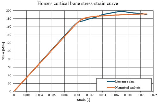


Figure 10.
The comparison of the static-tension diagram for a horse’s cortical bone—literature data compared to the developed Johnson–Cook model [41].

Table 1.
Material parameters used for numerical analyses [42,43,44].
Table 1.
Material parameters used for numerical analyses [42,43,44].
| Linear Simulations | ||||
|---|---|---|---|---|
| Material | E [GPa] | v [-] | ρ [kg/m3] | |
| 316L Steel | 200.0 | 0.29 | 7900 | |
| Cortical Bone | 17.0 | 0.30 | 1800 | |
| Trabecular Bone | 0.5 | 0.30 | 700 | |
| Non-linear simulations | ||||
| Material | A [MPa] | B [MPa] | n [-] | c [-] |
| 316L Steel | 490 | 600 | 0.21 | 0.015 |
| Cortical Bone | 150 | 58 | 0.21 | - |
| D1 [-] | D2 [-] | D3 [-] | D4 [-] | |
| 316L Steel | 0.05 | 3.44 | 2.12 | 0.002 |
| εlimit [-] | ||||
| Cortical Bone | 0.021 | |||
where: E—Young’s modulus, v—Poisson’s ratio, ρ—density, A—yield strength, B—strengthening constant, n—strengthening coefficient, c—strain rate coefficient, D1–D4—Johnson–Cook damage constants, and εlimit—maximum strain value.
3.3. Preparation of an Algorithm to Simulate the Bone Union Process
Mechanobiology deals with the study of the impact of mechanical loads on biological processes in tissues, especially at the cellular and tissue level. Computational mechanobiology is a branch of this science that uses mathematical models and computer simulations to determine exactly how mechanical forces affect cell differentiation, tissue remodelling processes, and its response to loads.
Mechanobiological models enable simulation of bone healing processes and other biological phenomena, eliminating the need to conduct expensive, time-consuming, and sometimes impossible physical experiments. As a result of them, we can predict how a given orthopaedic implant will behave in the patient’s body, whether bone fusion will occur and whether it will be accompanied by the risk of damage. These models also allow for selecting the optimal solution in a specific clinical situation, minimizing the need to experiment on living organisms [45,46,47].
The only frequently used mechanobiological model is the Carter model developed in 1984 based on Frost’s theory. In this mathematical model, mechanical stimuli, such as uniaxial compression and tension, play a key role, causing deformations and determining the adaptation and remodelling of bone tissue [48].
According to Carter, there is a close relationship between the mechanical signal and the rate of bone remodelling. Osteocytes, or bone cells, respond to these stimuli, with strain energy density being a key controlling factor. Maximum loads, generating the highest strain density, result in intensive remodelling of bone tissue [30,48].
Carter’s concept assumes the existence of three zones of relationship between the mechanical stimulus and changes in the tissue. This relationship is linear. When the strain density drops below a certain value, osteoclastic processes, i.e., tissue resorption, begin. The next range of mechanical stimulus values leads to achieving biological balance in which the processes of bone tissue resorption and construction are balanced. This zone, called the lazy zone, occurs with small load changes. The formation of bone tissue takes place when the mechanical stimulus exceeds a certain value. Figure 11 graphically presents the occurrence of defined zones of dependencies between the mechanical stimulus and changes in the tissue [49].
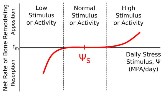
Figure 11.
The influence of a mechanical stimulus on adaptive changes in bone tissue—Carter’s model [49,50].
Carter’s algorithm (Figure 12) allows predicting changes in bone tissue density based on the value of the mechanical stimulus that will be generated in the tissue due to external loads. In the initial phase of the algorithm procedure, for each load iteration, calculations were made of the values of main stresses σi and main strains εi, on the basis of which, in the next step, the strain energy U0 was determined. In the next step, on the basis of the bone tissue density ρ known for each point of the model, the strain energy density and the effective stress σef were calculated. The next stage of the algorithm was to determine the value of the mechanical stimulus for each point of the model. The next step was to determine the surface of the active BS/TV bone tissue in which adaptation processes take place, based on the value of the remodelling speed m. Calculating this value allowed it to be used to check the density of bone tissue after adaptation caused by the influence of a given load. The final stage of each algorithm loop was to assign the bone density value to the corresponding Young’s modulus, based on the relationship (formula). The values of the α multiplier and the β exponent depend on the range in which the value of the previously determined bone tissue density lies. All parameters determined for one iteration of the algorithm were assigned to each element of the model and visualized as a distribution of material properties of bone tissue resulting from bone load [50]. The tests were carried out for two loads—353 N and 483 N. The goal was to determine the most optimal stabilization and force that would result in the most optimal reconstruction of the bone structure in terms of the speed of reconstruction and the uniform process of reconstruction. The model in the computing environment is as follows (Figure 13):
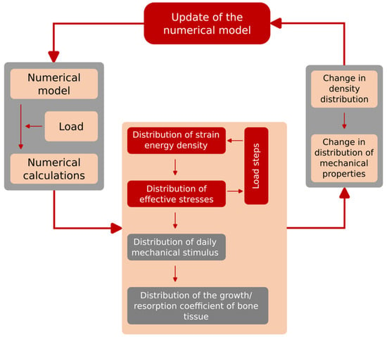
Figure 12.
Scheme of the developed and implemented Carter algorithm.
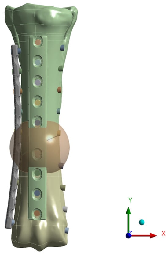
Figure 13.
Numerical model with a generated sphere—the place where the remodelling process is carried out.
4. Results
4.1. Results of Static Simulations
Static simulations allowed us to obtain the distributions of reduced Huber–Mises–Hencky (H–M–H) stresses in the implant and main bone stresses. The aim of this part of the analysis was to indicate whether the destabilization of the implant–bone system may occur in individual load cases. In addition, the distributions of nodal displacements on specific surfaces of the bone scar were obtained, which were then used to prepare the boundary conditions necessary for calculations regarding bone remodelling in the area of the fracture gap.
First, examples of stress values obtained for bones using anterior stabilization for various load values are presented (Figure 14), then lateral (Figure 15) and anterolateral (Figure 16).
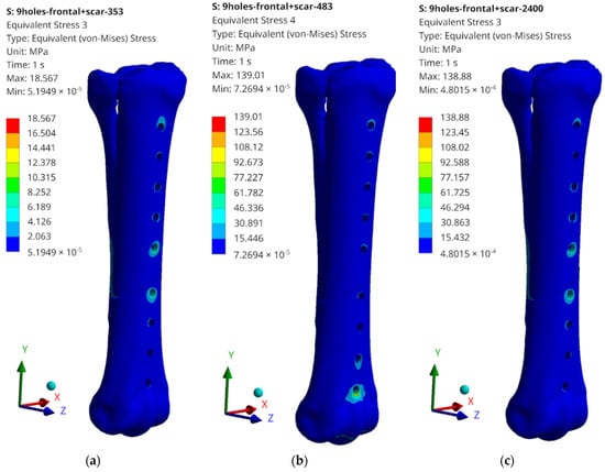
Figure 14.
Examples of obtained H–M–H stress distributions for anterior stabilization: (a) 353 N; (b) 483 N; and (c) 2400 N.
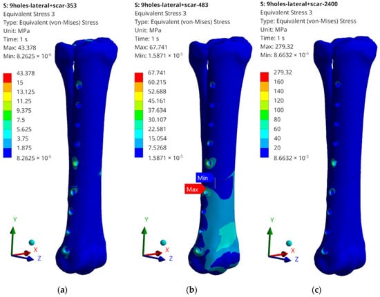
Figure 15.
Examples of obtained H–M–H stress distributions for lateral stabilization: (a) 353 N; (b) 483 N; and (c) 2400 N.
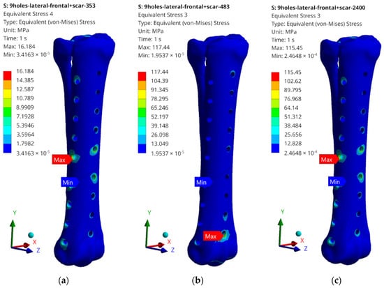
Figure 16.
Examples of obtained H–M–H stress distributions for anterolateral stabilization: (a) 353 N; (b) 483 N; and (c) 2400 N.
The obtained values of H–M–H stresses during static analysis do not indicate that the bone proportionality limit is exceeded. Stress concentrations occur at the edges of the holes where bone screws are placed. These values, however, do not exceed the critical value, except for the case of lateral stabilization and 2400 N load (Figure 15c). In order to systematize the obtained values and present them in a more transparent way, the rest of the results of the maximum stress values obtained as a result of the simulation are presented in the table below (Table 2).

Table 2.
Obtained stress values for individual elements of the implant–bone system.
What should be emphasized is that the force values do not exceed the critical values for cases 353 N and 483 N; therefore, the tests on the bone remodelling process were carried out for these load values. The highest values, significantly exceeding the yield strength values for the stabilizer material, were read for a load of 2400 N; therefore, no analysis of the reconstruction process was carried out, but only the damage propagation process was examined in the Abaqus/Explicit program. It is also worth mentioning the maximum stress values that were read during static tests. They most often occur in single elements in the screw–bone contact area, which may cause local stress concentration, but also be related to the tetra-type finite elements used.
4.2. Results of Dynamic Simulations
Research using the Abaqus/Explicit dynamic analysis program allowed us to determine the direction of propagation of damage to the implant–bone system after exceeding a safe force value—corresponding to the load occurring at 5.0 km/h. The performed numerical analyses allowed obtaining the values of stresses and displacements, as well as observations of the potential place of damage initiation. Below (Figure 17) are the simulation results for anterior, (Figure 18) lateral, and (Figure 19) anterolateral stabilization.
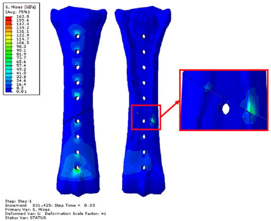
Figure 17.
Obtained H–M–H stress distributions for frontal stabilization during Abaqus/Explicit simulations for 2400 N. Simulation time 5 × 10⁻². Front and rear view.
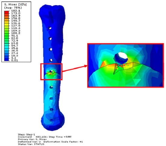
Figure 18.
Obtained H–M–H stress distributions for frontal stabilization during Abaqus/Explicit simulations for 2400 N. Simulation time 5 × 10⁻³. Side view—opposite side of the implant.
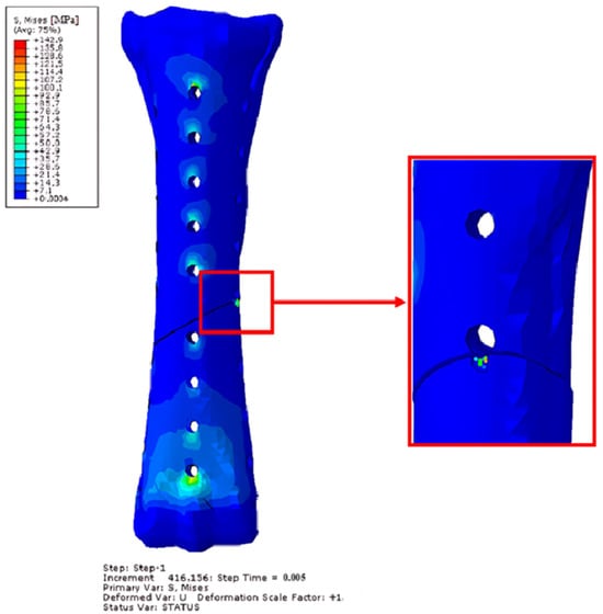
Figure 19.
Obtained H–M–H stress distributions for anterolateral stabilization during Abaqus/Explicit simulations for 2400 N. Simulation time 5 × 10⁻³. Front view.
In each case, the reason for the destabilization of the implant–bone system was the contact between bone fragments. The contact between these fragments caused damage to the bone elements in the case of lateral and anterolateral stabilization. Despite the simulation time being ten times longer for anterior stabilization, unlike the other two methods, no destruction of bone fragments was achieved. The effect of introducing a lateral stabilizer is particularly visible—the weakening of the bone in this place causes significant stresses of up to 190 MPa, which not only significantly exceeds the proportionality limit, but also exceeds the maximum strength limit and causes destruction. After damage to bone fragments, significant stress values were also observed in the implants. The table below (Table 3) shows the maximum stresses read for the stabilizers during the simulation.

Table 3.
Obtained H–M–H stress values for individual elements of the implant–bone system for 2400 N. Simulation time 5 × 10⁻² for front stabilization and 5 × 10⁻³ for lateral and anterolateral stabilization.
An example of the effect of the destruction of finite elements as a result of screw–stabilizer contact is visible below (Figure 20).
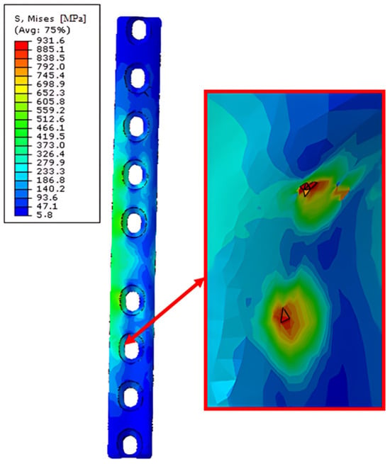
Figure 20.
Obtained H–M–H stress distributions for lateral stabilization during Abaqus/Explicit simulations for 2400 N. Simulation time 5 × 10⁻³. Point of the finite element destruction in screw–stabilization contact point.
The places where the material’s yield strength was significantly exceeded were the places where the screws contacted the implant, and these places may also be potential places of loss of stability between the implant–bone system.
4.3. Results of Bone Remodelling Process Simulations
The bone remodelling process is shown below (Figure 21). Each figure shows subsequent stages of the process of reconstruction (remodelling) of bone tissue. In addition, there are also markings for individual types of stabilization and load. F—frontal, L—lateral, F-L—anterolateral, 353–353 N and 483–483 N.
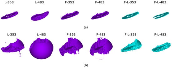
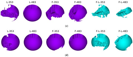
Figure 21.
The process of bone remodelling with various methods of stabilization and various loads: (a) first time step; (b) second time step; (c) third time step; and (d) last time step.
The best reconstruction conditions were obtained in the variant with lateral stabilization—this is also the most frequently used stabilization variant [51,52,53]. In the case of both standing and walking at slower speeds, bone tissue is obtained on at least three-quarters of the bone circumference. The bone scar undergoes complete mineralization during the period of complete ossification. In the case of anterior stabilization, the resulting mineralization of the bone scar is not complete, although it covers three-quarters of the circumference of the cortical bone. The weakest conditions for the mineralization of the bone scar are provided by two-plate stabilization. The obtained bone regenerated is much poorer and, after removing the stabilizers, may not provide an adequate connection of the fragments, or the time needed to achieve the full consolidation of the fragments may be extended. This is probably related to the too-stiff connection of the fragments within the achieved stabilization and the lack of appropriate micro-movements in the fracture gap.
5. Conclusions
Based on the conducted numerical research, several basic conclusions can be presented:
The algorithm for bone density changes was developed based on Carter’s model, which describes the adaptation of bone tissue to the loads it carries during activities. In the bone scarring model, the strain energy was calculated and, relative to the tissue density, also the strain energy density and effective stress, which allowed for the calculation of the mechanical stimulus value determining the process of adaptive changes.
Static analysis has shown that lateral stabilization is sufficient for providing appropriate conditions for an animal with a given weight of 120 kg. We are required to monitor the animal’s activity, as dynamic movement could destabilize the implant. At the same time, plastic deformations may occur at the edges of the implant holes, but these will not affect the possibility of the further stabilization of the fracture.
As shown by static analysis, the most promising results were obtained during lateral stabilization. At the same time, bone tissue remodelling simulations confirm that the results obtained using Carter’s algorithm also indicate that lateral stabilization offers the best chance for achieving a stable bone union, assuming moderate activity of the animal.
Research using dynamic solvers allowed for the determination of the potential area of destabilization and damage to the implant–bone system. The analyses carried out indicate that the main reason for the impossibility of using the stabilization system above a speed of 2.5 km/h is the damage to bone fragments that will undergo violent contact. This causes damage to the bone surface before the limits for the stabilization system are exceeded. In addition, single places of significant stress on the implant–screw system were also observed.
Author Contributions
Conceptualization: J.S. and R.H.; methodology: J.S.; software: J.S. and M.R.; validation: M.R. and K.K.; formal analysis: K.K.; investigation: J.S. and M.R.; resources: R.H.; data curation: J.S. and M.R.; writing—original draft preparation: M.R., J.S. and K.K.; writing—review and editing; R.H. and K.J.; visualization, J.S. and K.K.; supervision: K.J. and R.H.; project administration: K.J.; funding acquisition: J.S. and R.H. All authors have read and agreed to the published version of the manuscript.
Funding
This research received no external funding.
Institutional Review Board Statement
Not applicable.
Informed Consent Statement
Not applicable.
Data Availability Statement
The raw data supporting the conclusions of this article will be made available by the authors on request.
Acknowledgments
Calculations were carried out at the Wrocław Centre for Networking and Super-computing (http://www.wcss.pl, accessed 25 April 2024–15 May 2024), under grant No. 452 (accessed 25 April 2024–15 May 2024) and grant No. 397 (accessed 25 April 2024–15 May 2024). The authors wish to express their gratitude to Professor Maciej Janeczek, Head of the Department of Biostructure and Animal Physiology at the Faculty of Veterinary Medicine of the Wrocław University of Environmental and Life Sciences, for providing the specimen from teaching materials of the third metacarpal bone of a horse.
Conflicts of Interest
The authors declare no conflicts of interest.
References
- Auer, J.A.; Stick, J.A.; Kümmerle, J.M.; Prange, T. Equine Surgery, 5th ed.; Elsevier: Amsterdam, The Netherlands, 2018; pp. 1–1882. [Google Scholar] [CrossRef]
- Markel, M.D. Fracture Biomechanics; John Wiley & Sons Ltd.: Hoboken, NJ, USA, 2019; pp. 12–23. [Google Scholar] [CrossRef]
- Nixon, A.J. Equine Fracture Repair, 2nd ed.; Wiley-Blackwell: Hoboken, NJ, USA, 2019; ISBN 978-1-119-10875-7. [Google Scholar]
- McClure, S.R.; Watkins, J.P.; Glickman, N.W.; Hawkins, J.F.; Glickman, L.T. Complete Fractures of the Third Metacarpal or Metatarsal Bone in Horses: 25 Cases (1980–1996). J. Am. Vet. Med. Assoc. 1998, 213, 847–850. [Google Scholar] [CrossRef]
- Nixon, A.J.; Fortier, L.A. Fractures of the Small Metacarpal and Metatarsal (Splint) Bones. In Equine Fracture Repair; John Wiley & Sons Ltd.: Hoboken, NJ, USA, 2019; pp. 465–479. [Google Scholar] [CrossRef]
- Lescun, T.B.; McClure, S.R.; Ward, M.P.; Downs, C.; Wilson, D.A.; Adams, S.B.; Hawkins, J.F.; Reinertson, E.L. Evaluation of Transfixation Casting for Treatment of Third Metacarpal, Third Metatarsal, and Phalangeal Fractures in Horses: 37 Cases (1994–2004). J. Am. Vet. Med. Assoc. 2007, 230, 1340–1349. [Google Scholar] [CrossRef] [PubMed]
- Brianza, S.; Brighenti, V.; Lansdowne, J.L.; Schwieger, K.; Bouré, L. Finite Element Analysis of a Novel Pin-Sleeve System for External Fixation of Distal Limb Fractures in Horses. Vet. J. 2011, 190, 260–267. [Google Scholar] [CrossRef]
- Galuppo, L.D.; Stover, S.M.; Aldridge, A.; Hewes, C.; Taylor, K.T. An In Vitro Biomechanical Investigation of an MP35N Intramedullary Interlocking Nail System for Repair of Third Metacarpal Fractures in Adult Horses. Vet. Surg. 2002, 31, 211–225. [Google Scholar] [CrossRef] [PubMed]
- Berg, E.L.; Causey, A. The Life-Changing Power of the Horse: Equine-Assisted Activities and Therapies in the U.S. Anim. Front. 2014, 4, 72–75. [Google Scholar] [CrossRef]
- Borioni, N.; Marinaro, P.; Celestini, S.; Del Sole, F.; Magro, R.; Zoppi, D.; Mattei, F.; Dall’ Armi, V.; Mazzarella, F.; Cesario, A.; et al. Effect of Equestrian Therapy and Onotherapy in Physical and Psycho-Social Performances of Adults with Intellectual Disability: A Preliminary Study of Evaluation Tools Based on the ICF Classification. Disabil. Rehabil. 2012, 34, 279–287. [Google Scholar] [CrossRef]
- Diab, S.S.; Stover, S.M.; Carvallo, F.; Nyaoke, A.C.; Moore, J.; Hill, A.; Arthur, R.; Uzal, F.A. Diagnostic Approach to Catastrophic Musculoskeletal Injuries in Racehorses. J. Vet. Diagn. Investig. 2017, 29, 405–413. [Google Scholar] [CrossRef] [PubMed]
- Wright, I.M. Fractures of the Distal Condyles of the Third Metacarpal and Third Metatarsal Bones; John Wiley & Sons Ltd.: Hoboken, NJ, USA, 2022; pp. 445–484. [Google Scholar] [CrossRef]
- Choi, J.; Seo, H.J.; Shin, J.; Byun, J.H.; Jung, S.N. The Effect of Steroid and Mannitol Combination Treatment on Postoperative Rehabilitation of Multiple Metacarpal Bone Fractures. Medicina 2023, 59, 783. [Google Scholar] [CrossRef]
- Stewart, S.; Richardson, D.; Boston, R.; Schaer, T.P. Risk Factors Associated with Survival to Hospital Discharge of 54 Horses with Fractures of the Radius. Vet. Surg. 2015, 44, 1036–1041. [Google Scholar] [CrossRef]
- Bischofberger, A.S.; Fürst, A.; Auer, J.; Lischer, C. Surgical Management of Complete Diaphyseal Third Metacarpal and Metatarsal Bone Fractures: Clinical Outcome in 10 Mature Horses and 11 Foals. Equine Vet. J. 2009, 41, 465–473. [Google Scholar] [CrossRef]
- Kawcak, C.E. Bone Healing. In Fractures in the Horse; John Wiley & Sons Ltd.: Hoboken, NJ, USA, 2022; pp. 97–115. ISBN 9781119431749. [Google Scholar]
- Ercin, E.; Hurmeydan, O.M.; Karahan, M. Bone Anatomy and the Biologic Healing Process of a Fracture. In Bio-Orthopaedics: A New Approach; Springer: Berlin/Heidelberg, Germany, 2017; pp. 437–447. [Google Scholar] [CrossRef]
- Allen, M.; Burr, D. Chapter 4. Bone Modeling and Remodeling. In Basic and Applied Bone Biology; Academic Press: Cambridge, MA, USA, 2014; pp. 75–90. ISBN 9780124160156. [Google Scholar]
- Chamay, A.; Tschantz, P. Mechanical Influences in Bone Remodeling. Experimental Research on Wolff’s Law. J. Biomech. 1972, 5, 173–180. [Google Scholar] [CrossRef]
- Hadjiargyrou, M.; O’Keefe, R.J. The Convergence of Fracture Repair and Stem Cells: Interplay of Genes, Aging, Environmental Factors and Disease. J. Bone Miner. Res. 2014, 29, 2307–2322. [Google Scholar] [CrossRef]
- Firth, E.C.; Goodship, A.E.; Delahunt, J.; Smith, T. Osteoinductive Response in the Dorsal Aspect of the Carpus of Young Thoroughbreds in Training Occurs within Months. Equine Vet. J. Suppl. 1999, 30, 552–554. [Google Scholar] [CrossRef]
- Oryan, A.; Monazzah, S.; Bigham-Sadegh, A. Bone Injury and Fracture Healing Biology. Biomed. Environ. Sci. 2015, 28, 57–71. [Google Scholar] [CrossRef]
- Ortved, K.F.; Richardson, D.W. Complications of Equine Orthopedic Surgery. In Complications in Equine Surgery; John Wiley & Sons Ltd.: Hoboken, NJ, USA, 2021; pp. 629–666. ISBN 9781119190332. [Google Scholar]
- Lescun, T.B. Complications of Splint Bone Fractures. In Complications in Equine Surgery; John Wiley & Sons Ltd.: Hoboken, NJ, USA, 2021; pp. 718–729. ISBN 9781119190332. [Google Scholar]
- Levine, D.G.; Richardson, D.W. Clinical Use of the Locking Compression Plate (LCP) in Horses: A Retrospective Study of 31 Cases (2004–2006). Equine Vet. J. 2007, 39, 401–406. [Google Scholar] [CrossRef] [PubMed]
- Pilliner, S.; Elmhurst, S.; Davies, Z. The Horse in Motion; Willey-Blackweell: Hoboken, NJ, USA, 2002; pp. 197–202. ISBN 063205137X. [Google Scholar]
- Clayton, H.M.; Hobbs, S.J. Reference to Collected Trot, Passage and Piaffe in Dressage Horses. Animals 2019, 9, 763–782. [Google Scholar] [CrossRef] [PubMed]
- Merritt, J.S.; Pandy, M.G.; Brown, N.A.T.; Burvill, C.R.; Kawcak, C.E.; McIlwraith, C.W.; Davies, H.M.S. Mechanical Loading of the Distal End of the Third Metacarpal Bone in Horses during Walking and Trotting. J. Am. Vet. Med. Assoc. 2010, 71, 508–514. [Google Scholar] [CrossRef]
- Voutat, C.; Nohava, J.; Wandel, J.; Zysset, P. The Dynamic Friction Coefficient of the Wet Bone-Implant Interface: Influence of Load, Speed, Material and Surface Finish. Biotribology 2019, 17, 64–74. [Google Scholar] [CrossRef]
- Beaupré, G.S.; Orr, T.E.; Carter, D.R. An Approach for Time-Dependent Bone Modeling and Remodeling—Theoretical Development. J. Orthop. Res. 1990, 8, 651–661. [Google Scholar] [CrossRef]
- Toma, M.; Singh-Gryzbon, S.; Frankini, E.; Wei, Z.; Yoganathan, A.P. Clinical Impact of Computational Heart Valve Models. Materials 2022, 15, 3302. [Google Scholar] [CrossRef]
- Klekiel, T.; Arkusz, K.; Sławiński, G.; Malesa, P.; Będziński, R. Numerical Analyses of Fracture Mechanism of the Pelvic Ring during Side-Impact Load. Materials 2022, 15, 5734. [Google Scholar] [CrossRef]
- Sybilski, K.; Fernandes, F.A.O.; Ptak, M.; Alves de Sousa, R.J. Injury Biomechanics Evaluation of a Driver with Disabilities during a Road Accident—A Numerical Approach. Materials 2022, 15, 7956. [Google Scholar] [CrossRef] [PubMed]
- Barbosa, A.; Fernandes, F.A.O.; de Sousa, R.J.A.; Ptak, M.; Wilhelm, J. Computational Modeling of Skull Bone Structures and Simulation of Skull Fractures Using the YEAHM Head Model. Biology 2020, 9, 267. [Google Scholar] [CrossRef] [PubMed]
- Kuc, A.E.; Sybilski, K.; Kotuła, J.; Piątkowski, G.; Kowala, B.; Lis, J.; Saternus, S.; Sarul, M. The Hydrostatic Pressure Distribution in the Periodontal Ligament and the Risk of Root Resorption—A Finite Element Method (FEM) Study on the Nonlinear Innovative Model. Materials 2024, 17, 1661. [Google Scholar] [CrossRef]
- ABAQUS. Version 6.6. Analysis User’s Manual Documentation; Washington University in St. Louis: St. Louis, MO, USA, 2009. [Google Scholar]
- Nowicki, A.; Osypko, K.; Kurzawa, A.; Roszak, M.; Krawiec, K.; Pyka, D. Mechanical and Material Analysis of 3D-Printed Temporary Materials for Implant Reconstructions—A Pilot Study. Biomedicines 2024, 12, 870. [Google Scholar] [CrossRef]
- Zhang, D.-N.; Shangguan, Q.-Q.; Xie, C.-J.; Liu, F. A Modified Johnson–Cook Model of Dynamic Tensile Behaviors for 7075-T6 Aluminum Alloy. J. Alloys Compd. 2015, 619, 186–194. [Google Scholar] [CrossRef]
- Murugesan, M.; Jung, D.W. Johnson Cook Material and Failure Model Parameters Estimation of AISI-1045 Medium Carbon Steel for Metal Forming Applications. Materials 2019, 12, 609. [Google Scholar] [CrossRef] [PubMed]
- Zochowski, P.; Bajkowski, M.; Grygoruk, R.; Magier, M.; Burian, W.; Pyka, D.; Bocian, M.; Jamroziak, K. Comparison of Numerical Simulation Techniques of Ballistic Ceramics under Projectile Impact Conditions. Materials 2022, 15, 18. [Google Scholar] [CrossRef]
- Atkins, A.; Dean, M.N.; Habegger, M.L.; Motta, P.J.; Ofer, L.; Repp, F.; Shipov, A.; Weiner, S.; Currey, J.D.; Shahar, R. Remodeling in Bone without Osteocytes: Billfish Challenge Bone Structure-Function Paradigms. Proc. Natl. Acad. Sci. USA 2014, 111, 16047–16052. [Google Scholar] [CrossRef]
- Bigley, R.F.; Gibeling, J.C.; Stover, S.M.; Hazelwood, S.J.; Fyhrie, D.P.; Martin, R.B. Volume Effects on Yield Strength of Equine Cortical Bone. J. Mech. Behav. Biomed. Mater. 2008, 1, 295–302. [Google Scholar] [CrossRef][Green Version]
- Lescun, T.B.; Adams, S.B.; Main, R.P.; Nauman, E.A.; Breur, G.J. Finite Element Analysis of Six Transcortical Pin Parameters and Their Effect on Bone-Pin Interface Stresses in the Equine Third Metacarpal Bone. Vet. Comp. Orthop. Traumatol. 2020, 33, 121–129. [Google Scholar] [CrossRef] [PubMed]
- Elkaseer, A.; Abdelaziz, A.; Saber, M.; Nassef, A. FEM-Based Study of Precision Hard Turning of Stainless Steel 316L. Materials 2019, 12, 2522. [Google Scholar] [CrossRef] [PubMed]
- Harbin, Z.; Sohutskay, D.; Vanderlaan, E.; Fontaine, M.; Mendenhall, C.; Fisher, C.; Voytik-Harbin, S.; Tepole, A.B. Computational Mechanobiology Model Evaluating Healing of Postoperative Cavities Following Breast-Conserving Surgery. Comput. Biol. Med. 2023, 165, 107342. [Google Scholar] [CrossRef] [PubMed]
- Gharahi, H.; Garimella, H.T.; Chen, Z.J.; Gupta, R.K.; Przekwas, A. Mathematical Model of Mechanobiology of Acute and Repeated Synaptic Injury and Systemic Biomarker Kinetics. Front. Cell. Neurosci. 2023, 17, 1007062. [Google Scholar] [CrossRef]
- Mao, W.; Huai, Y.; Wang, X.; Hu, L.; Qian, A.; Chen, Z. Chapter 2—Methods and Models of Bone Cell Mechanobiology. In Bone Cell Biomechanics, Mechanobiology and Bone Diseases; Qian, A., Hu, L., Mechanobiology and Bone Diseases, L.B.T.-B.C.B., Eds.; Academic Press: Cambridge, MA, USA, 2024; pp. 31–52. ISBN 978-0-323-96123-3. [Google Scholar]
- Martin, R.B. Toward a Unifying Theory of Bone Remodeling. Bone 2000, 26, 1–6. [Google Scholar] [CrossRef]
- Hernandez, C.J.; Beaupré, G.S.; Carter, D.R. A Model of Mechanobiologic and Metabolic Influences on Bone Adaptation. J. Rehabil. Res. Dev. 2000, 37, 235–244. [Google Scholar]
- Słowiński, J. Analysis of the Stress State in the Design of an Individual Bone Implant. Doctoral Thesis, Wrocław University of Science and Technology Publishing House, Wrocław, Poland, 2011. [Google Scholar]
- Carol, M.; Granella, S.; Souza, F. De External Skeletal Fixation in Large Animals: A Review. Appl. Vet. Res. 2024, 3, 2024004. [Google Scholar]
- Brabon, A.; Hughes, K.J.; Jensen, K.; Xie, G.; Labens, R. Influence of Screw Configuration on Reduction and Stabilization of Simulated Complete Lateral Condylar Fracture in Equine Limbs. Vet. Surg. 2024, 53, 447–459. [Google Scholar] [CrossRef]
- Fürst, A.E.; Jackson, M.A. Comminuted Fractures of the Proximal Third of the Fourth Metatarsal Bone: Treatment Strategies. Equine Vet. Educ. 2023, 35, 628–631. [Google Scholar] [CrossRef]
Disclaimer/Publisher’s Note: The statements, opinions and data contained in all publications are solely those of the individual author(s) and contributor(s) and not of MDPI and/or the editor(s). MDPI and/or the editor(s) disclaim responsibility for any injury to people or property resulting from any ideas, methods, instructions or products referred to in the content. |
© 2024 by the authors. Licensee MDPI, Basel, Switzerland. This article is an open access article distributed under the terms and conditions of the Creative Commons Attribution (CC BY) license (https://creativecommons.org/licenses/by/4.0/).