
Secure Beamforming Design for UAV-Empowered Integrated Sensing and Communication

Abstract
1. Introduction
- (1)
- Given the security concerns of the UAV-assisted ISAC system, we tackle the challenge of detecting eavesdroppers while facilitating communication with legitimate users. Under the constraints of transmit power, legitimate communication quality of service, and sensing beam pattern gain, the problem is formulated as a joint optimization of UAV positioning and communication and sensing beamforming, aiming to minimize the maximum eavesdropping SINR.
- (2)
- Owing to the coupling between UAV communication and sensing beamforming, coupled with the intricate relationship between UAV positioning and steering vectors, the problem is inherently non-convex. To address this, the problem is decomposed into two sub-problems: beamforming optimization and UAV positioning optimization. For the UAV positioning sub-problem, a SCA algorithm, leveraging the first-order Taylor expansion, is employed to transform the non-convex problem into a convex one. This problem is subsequently resolved using the CVX toolbox.
- (3)
- For the beamforming optimization sub-problem, the max-min problem is addressed by introducing slack variables, and the fractional optimization problem is solved using the Dinkelbach method. The optimal beamforming is then determined using the semidefinite relaxation algorithm by ignoring the rank-one constraint and solving through eigenvalue decomposition. Simulation results indicate that the proposed algorithm substantially improves the security performance of the ISAC system, concurrently maintaining robust communication and sensing capabilities.
2. System Model and Problem Formulation
2.1. Communication Model
2.2. Sensing Model
- (1)
- Several legitimate users will actively transmit signals to the UAV, providing their identity and location information. The UAV authenticates this information, and if it passes, the users are confirmed as legitimate. Otherwise, they are considered eavesdroppers.
- (2)
- The UAV then sends an authentication request to the remaining users. Some users will respond to the authentication request, and the UAV will authenticate this information; if it passes, they are identified as legitimate users. Otherwise, they are considered eavesdroppers.
- (3)
- If a user neither actively transmits identity information nor responds to the UAV authentication request, the UAV considers them an eavesdropper.
2.3. Problem Formulation
3. Joint Optimization Algorithm
3.1. Transmit Beamforming Optimization
| Algorithm 1: UAV transmit beamforming optimization |
| Input: , , , , , Output: and 1. Given the initial value , set the minimum increment . 2. Repeat: 3. Solve the optimization problem to obtain , . 4. Perform EVD decomposition on and to obtain and . 5. Update according to Equation (15). 6. Until: The objective function increment is less than . |
3.2. UAV Position Optimization
- The left and right sides of are taken as the base-2 logarithm, reformulated as:where
- 2.
- Convert the inequality constraint into a polynomial form:
- 3.
- The inequality constraint can be reformulated as:
| Algorithm 2: UAV position optimization |
| Input: , , , , , , , , Output: 1. Initialize iteration count and , setting the minimum trust region radius . 2. Repeat: 3. Solve the optimization problem to obtain . 4. If the objective function value decreases, then 5. , . 6. else 7. . 8. end if 9. Until |
3.3. Joint Beamforming and UAV Positioning Optimization
| Algorithm 3: Joint beamforming and UAV positioning optimization |
| Input: , , , , , , , Output: , and 1. Initialize iteration count , . 2. Repeat: 3. Given the initial UAV position , update and using Algorithm 1. 4. Given the transmitting beamforming and , update using Algorithm 2. 5. . 6. Until: the objective function value of converges or . |
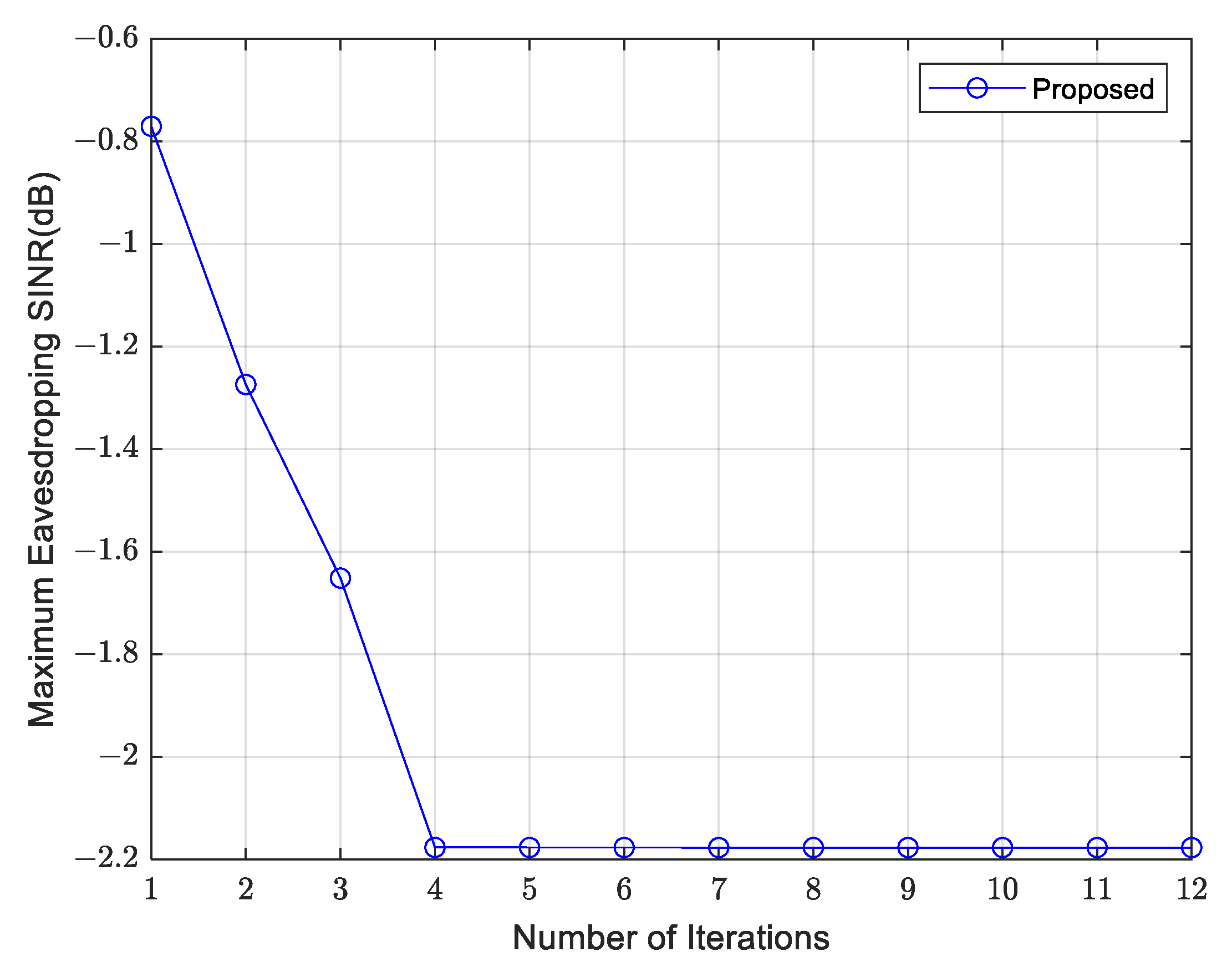
- Convergence: Define , , and as the -th iteration solutions of Algorithm 3, and let the objective function of problem be denoted as . In Step 3 of Algorithm 3, by fixing , we obtain and , thus:
- 2.
- Complexity: In Algorithm 3, we solve all subproblems using CVX. The first subproblem is a SDR problem, and the second subproblem is a SCA problem. The algorithmic complexities of the two subproblems are and , respectively [12], where denotes the number of iterations required for the algorithm to achieve convergence, and represents the convergence accuracy of the algorithm. Consequently, the worst-case computational complexity of Algorithm 3 is .
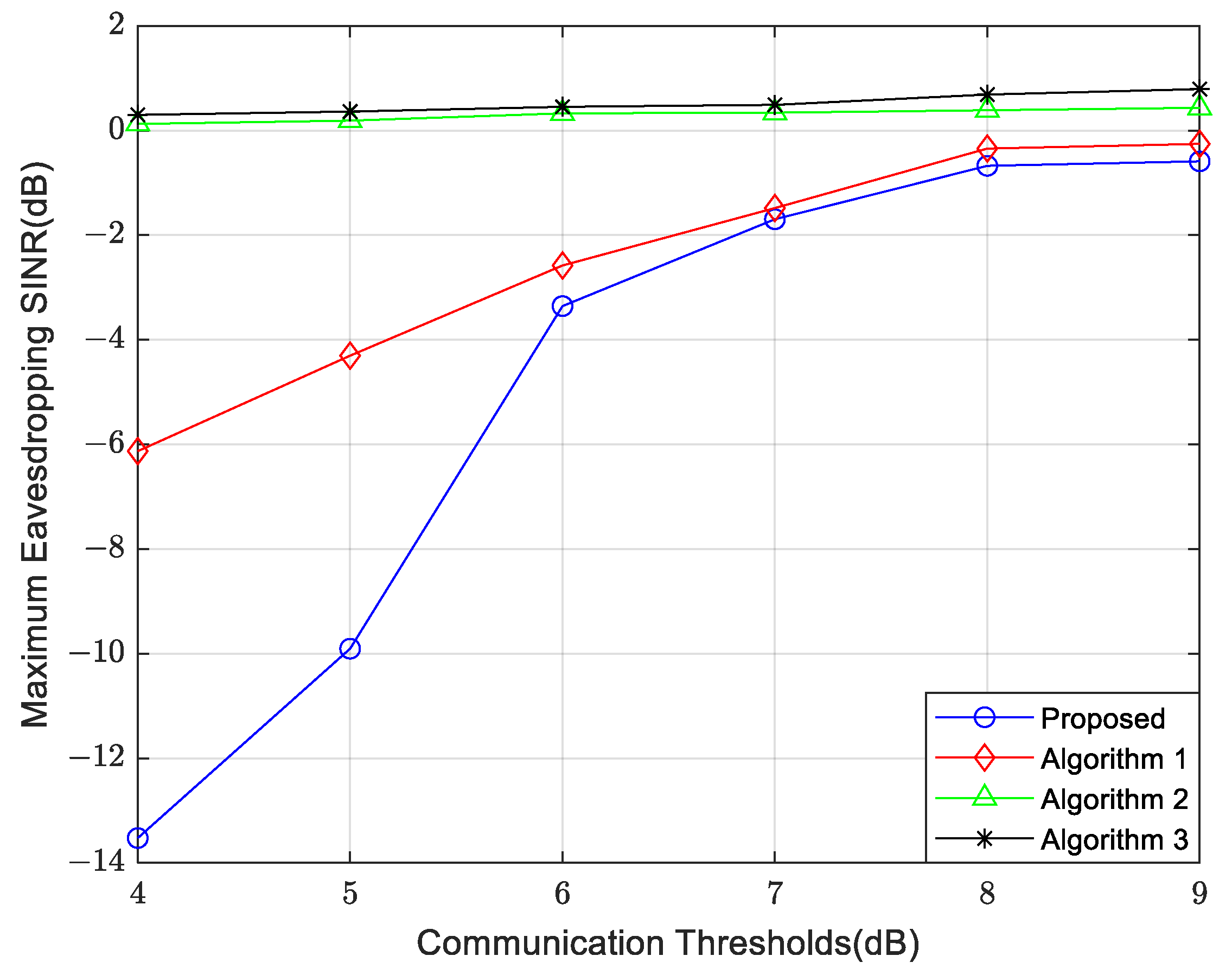
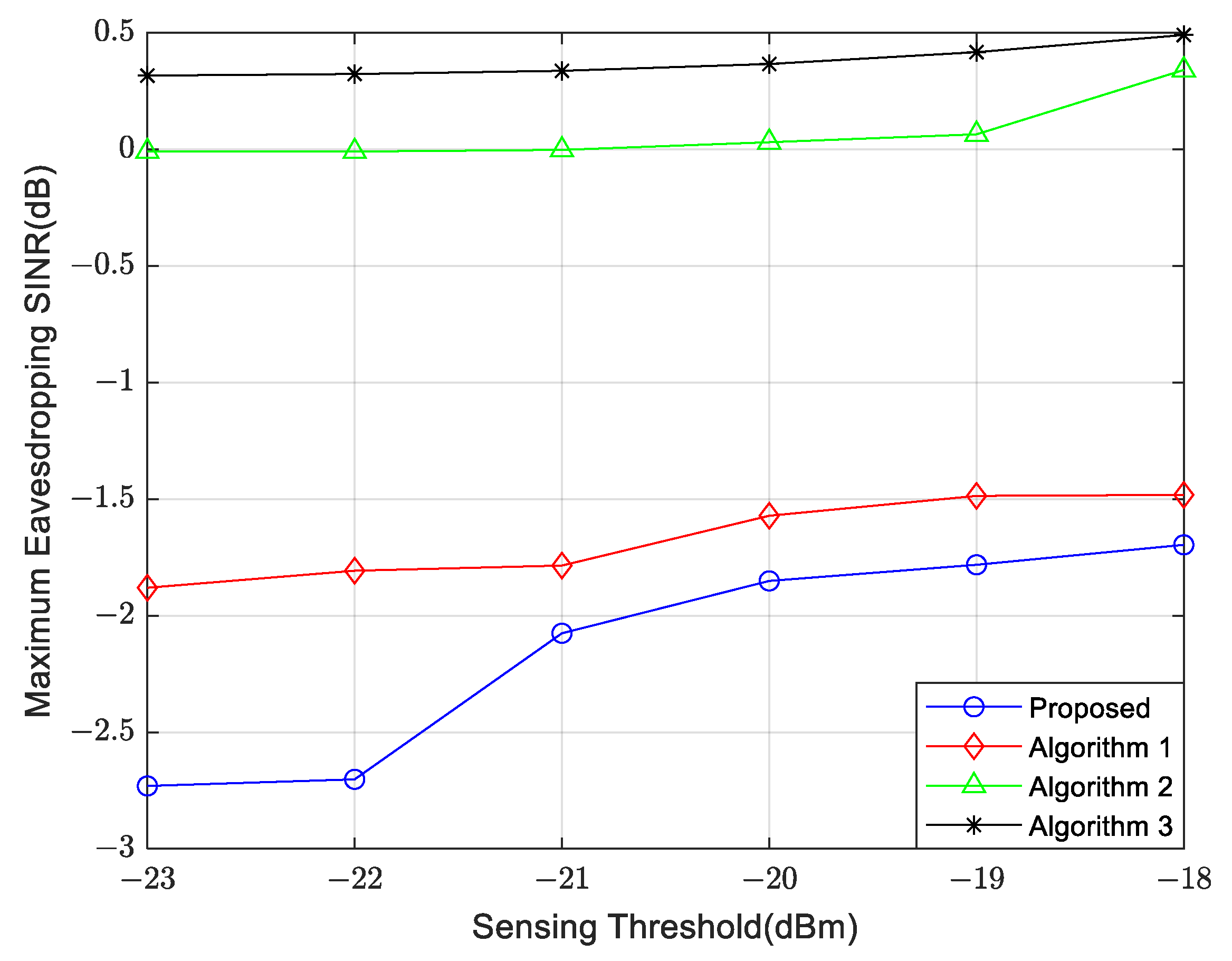
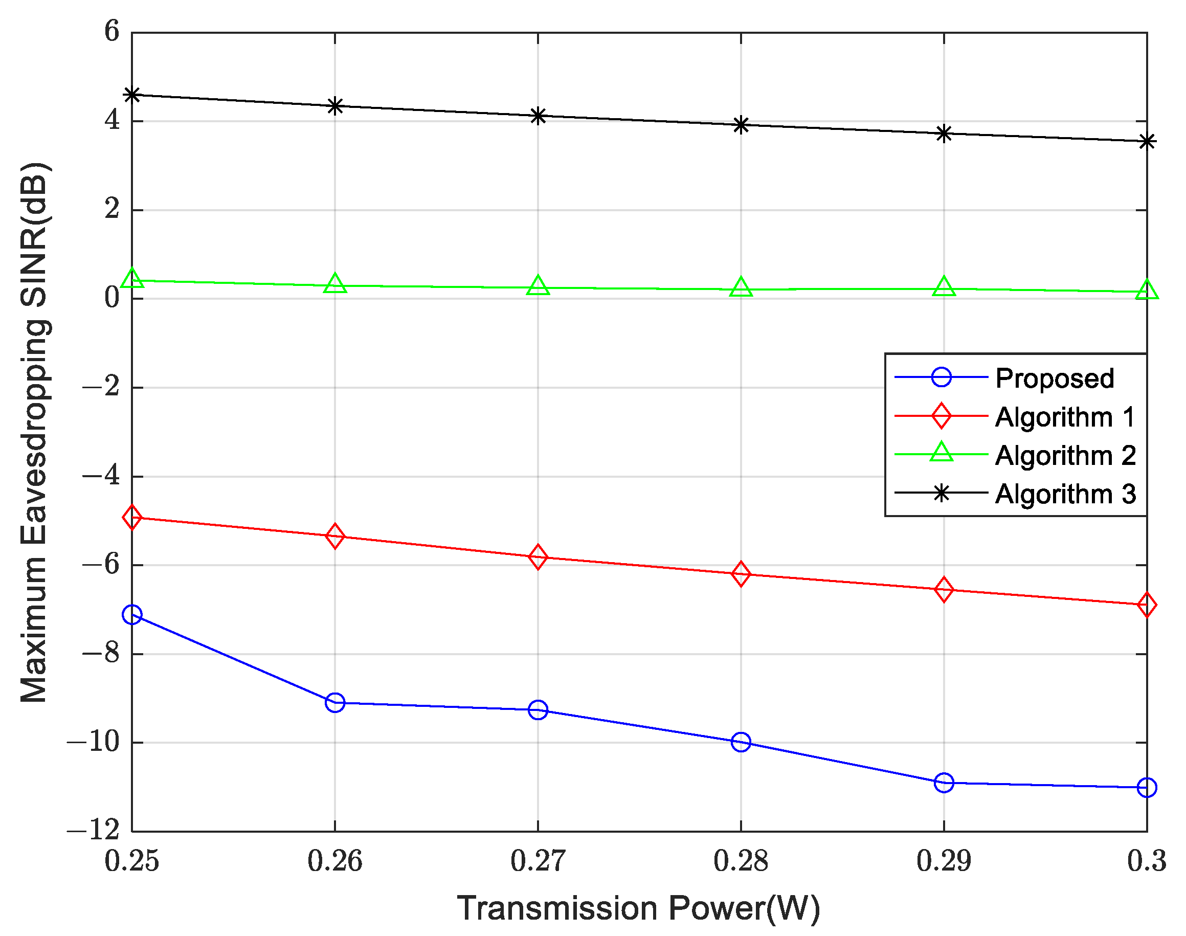
4. Simulation Results and Performance Analysis
- Comparison Algorithm 1: Only optimize the UAV transmit beamforming without optimizing the UAV position.
- Comparison Algorithm 2: In this algorithm, the UAV transmitted signal contains only communication signals without dedicated sensing signals. Similar to Algorithm 1, it optimizes both the UAV transmit beamforming and the UAV position.
- Comparison Algorithm 3: The UAV transmitted signal contains only communication signals without dedicated sensing signals. It optimizes the UAV transmit beamforming but not the UAV position.
5. Conclusions
Author Contributions
Funding
Institutional Review Board Statement
Informed Consent Statement
Data Availability Statement
Conflicts of Interest
References
- Fu, Y.; Shan, Y.; Zhu, Q.; Hung, K.; Wu, Y.; Quek, T.Q.S. A distributed microservice-aware paradigm for 6g: Challenges, principles, and research opportunities. IEEE Netw. 2023, 38, 163–170. [Google Scholar] [CrossRef]
- Wei, Z.; Qu, H.; Wang, Y.; Yuan, X.; Wu, H.; Du, Y.; Han, K.; Zhang, N.; Feng, Z. Integrated sensing and communication signals toward 5g-a and 6g: A survey. IEEE Internet Things J. 2023, 10, 11068–11092. [Google Scholar] [CrossRef]
- Liu, C.; Yuan, W.; Li, S.; Liu, X.; Li, H.; Ng, D.W.K.; Li, Y. Learning-based predictive beamforming for integrated sensing and communication in vehicular networks. IEEE J. Sel. Areas Commun. 2022, 40, 2317–2334. [Google Scholar] [CrossRef]
- Cheng, X.; Duan, D.; Gao, S.; Yang, L. Integrated sensing and communications (ISAC) for vehicular communication networks (VCN). IEEE Internet Things J. 2022, 9, 23441–23451. [Google Scholar] [CrossRef]
- Wu, Q.; Xu, J.; Zeng, Y.; Ng, D.W.K.; Al-Dhahir, N.; Schober, R.; Swindlehurst, A.L. A comprehensive overview on 5G-and-beyond networks with UAVs: From communications to sensing and intelligence. IEEE J. Sel. Areas Commun. 2021, 39, 2912–2945. [Google Scholar] [CrossRef]
- Li, J.; Liu, N. Integrated sensing and communication beamforming design based on mutual information. In Proceedings of the 2022 IEEE/CIC International Conference on Communications in China (ICCC Workshops), Foshan, China, 11–13 August 2022; pp. 383–388. [Google Scholar]
- Hua, H.; Xu, J.; Han, T.X. Optimal transmit beamforming for integrated sensing and communication. IEEE Trans. Veh. Technol. 2023, 72, 10588–10603. [Google Scholar] [CrossRef]
- Hua, H.; Han, T.X.; Xu, J. MIMO integrated sensing and communication: CRB-rate tradeoff. IEEE Trans. Wirel. Commun. 2023, 23, 2839–2854. [Google Scholar] [CrossRef]
- Sankar, R.S.P.; Chepuri, S.P.; Eldar, Y.C. Beamforming in integrated sensing and communication systems with reconfigurable intelligent surfaces. IEEE Trans. Wirel. Commun. 2023, 23, 4017–4031. [Google Scholar] [CrossRef]
- Luo, H.; Liu, R.; Li, M.; Liu, Y.; Liu, Q. Joint beamforming design for RIS-assisted integrated sensing and communication systems. IEEE Trans. Veh. Technol. 2022, 71, 13393–13397. [Google Scholar] [CrossRef]
- Lyu, Z.; Zhu, G.; Xu, J. Joint maneuver and beamforming design for UAV-enabled integrated sensing and communication. IEEE Trans. Wirel. Commun. 2022, 22, 2424–2440. [Google Scholar] [CrossRef]
- Deng, C.; Fang, X.; Wang, X. Beamforming design and trajectory optimization for UAV-empowered adaptable integrated sensing and communication. IEEE Trans. Wirel. Commun. 2023, 22, 8512–8526. [Google Scholar] [CrossRef]
- Jiang, W.; Shen, C.; Ai, B. UAV-assisted sensing and communication design for average peak age-of-information minimization. In Proceedings of the 2022 IEEE/CIC International Conference on Communications in China (ICCC Workshops), Foshan, China, 11–13 August 2022; pp. 1005–1010. [Google Scholar]
- Wu, J.; Yuan, W.; Bai, L. On the interplay between sensing and communications for UAV trajectory design. IEEE Internet Things J. 2023, 10, 20383–20395. [Google Scholar] [CrossRef]
- Wu, J.; Yuan, W.; Liu, F.; Cui, Y.; Meng, X.; Huang, H. UAV-based target tracking: Integrating sensing into communication signals. In Proceedings of the 2022 IEEE/CIC International Conference on Communications in China (ICCC Workshops), Foshan, China, 11–13 August 2022; pp. 309–313. [Google Scholar]
- Su, N. Physical Layer Security in Integrated Sensing and Communication Systems. Ph.D. Thesis, University College London, London, UK, 2023. [Google Scholar]
- Chu, J.; Liu, R.; Li, M.; Liu, Y.; Liu, Q. Joint secure transmit beamforming designs for integrated sensing and communication systems. IEEE Trans. Veh. Technol. 2022, 72, 4778–4791. [Google Scholar] [CrossRef]
- Su, N.; Liu, F.; Masouros, C. Sensing-assisted eavesdropper estimation: An ISAC breakthrough in physical layer security. IEEE Trans. Wirel. Commun. 2023, 23, 3162–3174. [Google Scholar] [CrossRef]
- Hua, M.; Wu, Q.; Chen, W.; Dobre, O.A.; Swindlehurst, A.L. Secure intelligent reflecting surface-aided integrated sensing and communication. IEEE Trans. Wirel. Commun. 2023, 23, 575–591. [Google Scholar] [CrossRef]
- Li, B.; Liao, J.; Gong, X.; Xiang, H.; Yang, Z.; Zhao, W. UAV-assisted ISAC network physical layer security based on Stackelberg game. Ad Hoc Netw. 2024, 152, 103304. [Google Scholar] [CrossRef]
- Wei, Z.; Liu, F.; Liu, C.; Yang, Z.; Ng, D.W.K.; Schober, R. Integrated sensing, navigation, and communication for secure UAV networks with a mobile eavesdropper. arXiv 2023, arXiv:2305.12842. [Google Scholar] [CrossRef]
- Meng, K.; Wu, Q.; Ma, S.; Chen, W.; Wang, K.; Li, J. Throughput maximization for UAV-enabled integrated periodic sensing and communication. IEEE Trans. Wirel. Commun. 2023, 22, 671–687. [Google Scholar] [CrossRef]


| Symbol | Definitions | Symbol | Definitions |
|---|---|---|---|
| Number of antennas | Transmitted signal of the UAV | ||
| , | Number of users and eavesdroppers | Maximum transmit power | |
| , | Communication signal and sensing signal | , , | Location of UAV, user k and eavesdropper |
| , | Beamforming vector | Communication channel from the UAV to the user | |
| Beamforming steering vector | Eavesdropping channel | ||
| , | Additive white Gaussian noise | , | Noise power spectral density |
| Beam pattern gain | , | Threshold of communication and sensing | |
| , , | Slack variables | Trust region radius |
Disclaimer/Publisher’s Note: The statements, opinions and data contained in all publications are solely those of the individual author(s) and contributor(s) and not of MDPI and/or the editor(s). MDPI and/or the editor(s) disclaim responsibility for any injury to people or property resulting from any ideas, methods, instructions or products referred to in the content. |
© 2024 by the authors. Licensee MDPI, Basel, Switzerland. This article is an open access article distributed under the terms and conditions of the Creative Commons Attribution (CC BY) license (https://creativecommons.org/licenses/by/4.0/).
Share and Cite
Chen, C.; Zhu, Q. Secure Beamforming Design for UAV-Empowered Integrated Sensing and Communication. Appl. Sci. 2024, 14, 7196. https://doi.org/10.3390/app14167196
Chen C, Zhu Q. Secure Beamforming Design for UAV-Empowered Integrated Sensing and Communication. Applied Sciences. 2024; 14(16):7196. https://doi.org/10.3390/app14167196
Chicago/Turabian StyleChen, Chuang, and Qi Zhu. 2024. "Secure Beamforming Design for UAV-Empowered Integrated Sensing and Communication" Applied Sciences 14, no. 16: 7196. https://doi.org/10.3390/app14167196
APA StyleChen, C., & Zhu, Q. (2024). Secure Beamforming Design for UAV-Empowered Integrated Sensing and Communication. Applied Sciences, 14(16), 7196. https://doi.org/10.3390/app14167196