1. Introduction
Presently, coal-fired power generation represents more than 40% of the world’s total energy generation. It is anticipated that coal will continue to be a significant component of the global energy mix for a considerable period of time. Encountering the context of achieving carbon peaking and carbon neutrality, it is imperative for the coal industry to continuously advance towards high productivity, efficiency, and safety, necessitating constant development [
1,
2,
3].
During coal mining operations, excavation and coal extraction represent the primary production stages. Initially, mining preparation tunnels are excavated using mechanical methods and blasting techniques. Subsequently, specialized coal mining machinery is deployed at the working face to facilitate longwall mechanized coal extraction.
Given the rapid technological advancements, the mining and tunneling processes and equipment in underground coal mines require immediate development to meet the high demand for coal energy in China and fulfill the expectations of unmanned and intelligent underground operations. However, despite the rapid progress in mining technology, the development of tunneling technology has significantly lagged behind fully mechanized mining methods. The speed of roadway excavation is considerably slower compared to mining, leading to a growing disparity between the two processes [
4]. Since 2001, the mining-to-tunneling ratio has consistently increased from 1:2.25 to approximately 1:3.2, resulting in the inefficiency of tunneling hampering the speed and effectiveness of coal extraction [
5]. Hence, it is imperative to elevate the level of tunneling technology and enhance the equipment used in underground coal mines to facilitate swift excavation and enhance both tunneling and mining efficiency.
Currently, the lack of effective temporary support is the primary obstacle to the development of roadway boring speed, preventing simultaneous excavation and support operations [
6,
7]. To address the issue of perimeter rock damage in deep roadways, the conventional operating method involves alternating between excavation and anchor support. However, this approach does not allow for a highly efficient parallel operation of the tunneling machine and support system, with support activities accounting for 70% of the overall cycle process [
8]. Consequently, the excavation efficiency is significantly hampered, leading to frequent start–stop of the boring machine and increased demand for personnel, thereby impeding the progress towards underground intelligence and automation while compromising equipment and worker safety.
The only way to solve the aforementioned issues is to introduce efficient and safe temporary support equipment at the tunneling face, thereby establishing a novel methodology that incorporates parallel operations of excavation, temporary support, and anchoring. Temporary support can be classified into two categories: non-repetitive temporary support and stepping repetitive temporary support. Non-repetitive temporary support involves a non-repetitive roof support approach, which mitigates any potential secondary damage. However, it often necessitates equipment relocation, resulting in operational complexity and spatial limitations. In light of these considerations, this study adopts the stepping temporary support technology approach, designs twin-link stepping temporary support equipment, and concurrently develops a comprehensive set of excavation, support, and anchoring equipment based on the twin-link stepping temporary support strategy. Consequently, a novel tunneling procedure is established, whereby excavation, temporary support, and anchoring operations are performed simultaneously, leading to significant improvements in both efficiency and safety.
However, during the process of implementing stepped temporary support, repetitive supporting actions are carried out on the roof. This may lead to additional damages and significant safety concerns, particularly when the roof is weak or subject to high original rock stress. As a result, the application of stepped temporary support is limited to a specific range of roof conditions. To address the applicability requirements of stepped temporary support for the roof, this research employs numerical simulation methodology based on the principles of stepped temporary support. It investigates the repetitiveness of support for various roadway roofs and establishes the applicable scope of stepped temporary support for roof conditions. The outcomes of this study effectively address the essential challenge faced during the practical implementation of stepped temporary support.
Currently, numerous researchers and institutions have conducted extensive studies on temporary support and numerical simulation of tunnels. Geological conditions in many coal-producing countries, including Europe and America, are generally favorable, displaying robust stability of tunnel roofs and floors. Consequently, the adoption of integrated cutting and anchoring units, which obviate the need for temporary support, has become commonplace, resulting in limited research regarding this aspect. Reverberating studies chiefly concentrate on China, which possesses tunnels characterized by distinctive features and intricate geological conditions. Zhao [
9] proposed a self-moving auxiliary support device in which two brackets mutually provided support, and self-movement was achieved through a displacement cylinder. Xie et al. [
10] introduced a temporary support device that follows the tunneling machine, establishing contact with the tunnel roof through a staggered bracket work structure. It successfully accomplished tasks such as installing mesh anchors for permanent support. Lu [
11] presented a temporary support device suitable for fully mechanized drivage. By utilizing alternating main and auxiliary support groups, it effectively supported the tunnel roof and achieved autonomous movement in a step-like manner. Ding et al. [
12] presented a temporary support scheme specifically designed to meet the mechanical requirements of the surrounding rock support system in the working face. They conducted an analysis of the mechanical characteristics of a self-moving temporary support and designed it accordingly. Xue et al. [
13] proposed a collection of robotized self-moving anchor support units. They established a mechanical coupling model of the surrounding rock of tunnels and advanced support brackets, using the Qishan Mine as an exemplar. By employing the finite element method, they analyzed the stress distribution and strength of the self-moving advance support unit. Kang et al. [
14] studied the stress distribution, deformation, and failure characteristics of the surrounding rock at the tunneling face through numerical simulation. Li et al. [
15] developed advanced non-repetitive mechanical movement support equipment and conducted an analysis on support timing and strength verification.
Through analysis of existing research, several scholars have proposed temporary support equipment for tunneling faces using a stepping support approach. However, the reliability and practicality of this equipment are limited. Furthermore, while some scholars have conducted numerical simulations on roadways, there is a lack of research on the repeatability of roadway roof support in tunneling faces. To address these gaps, this study focuses on temporary support in tunneling faces. Firstly, we designed and developed a twin-link stepping temporary support equipment to establish a new process that integrates excavation, temporary support, and anchor support operations. Secondly, to assess the suitability of stepping temporary support for the roadway roof, we constructed a numerical model of the stepping temporary support operation based on the principles of stepping temporary support and utilized 3DEC software. Through an analysis of underground conditions, we investigated the repeatability of support for various types of roadway roof rock, thicknesses, and depths, obtaining the range of sustainable roof support and the applicable conditions for the twin-link stepping temporary support.
2. Twin-Link Stepping Temporary Support Mechanism
2.1. Introduction to the Complete Set of Equipment for the Excavation and Support Anchor System Based on Twin-Link Stepping Temporary Support
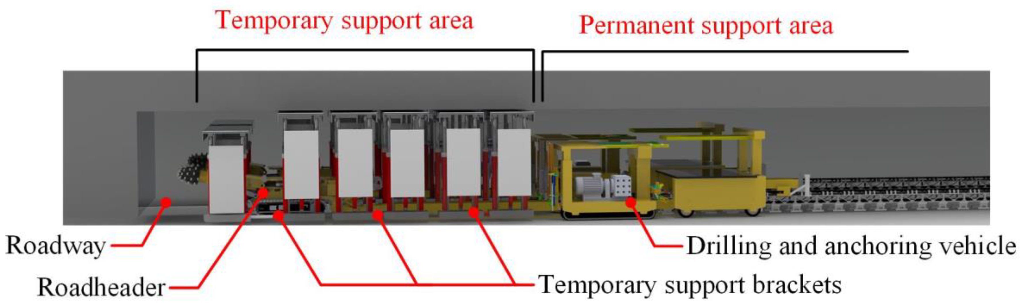
The comprehensive set of excavation, support, and anchoring equipment, which is based on the twin-link stepping temporary support system, comprises a roadheader, multiple sets of twin-link stepping temporary support units, drilling and anchoring vehicle, bridge-type loading machines, belt conveyors, emulsion pumping stations, and other necessary equipment. The multiple sets of twin-link stepping units serve as temporary support for the working face of the excavation roadway. This equipment set is utilized to carry out various processes, including roadway excavation, temporary support, permanent support, and coal transportation.
Figure 1 illustrates the layout arrangement of the complete equipment set, with the roadheader, temporary support brackets, drilling and anchoring vehicle, and loading machines arranged sequentially along the centerline.
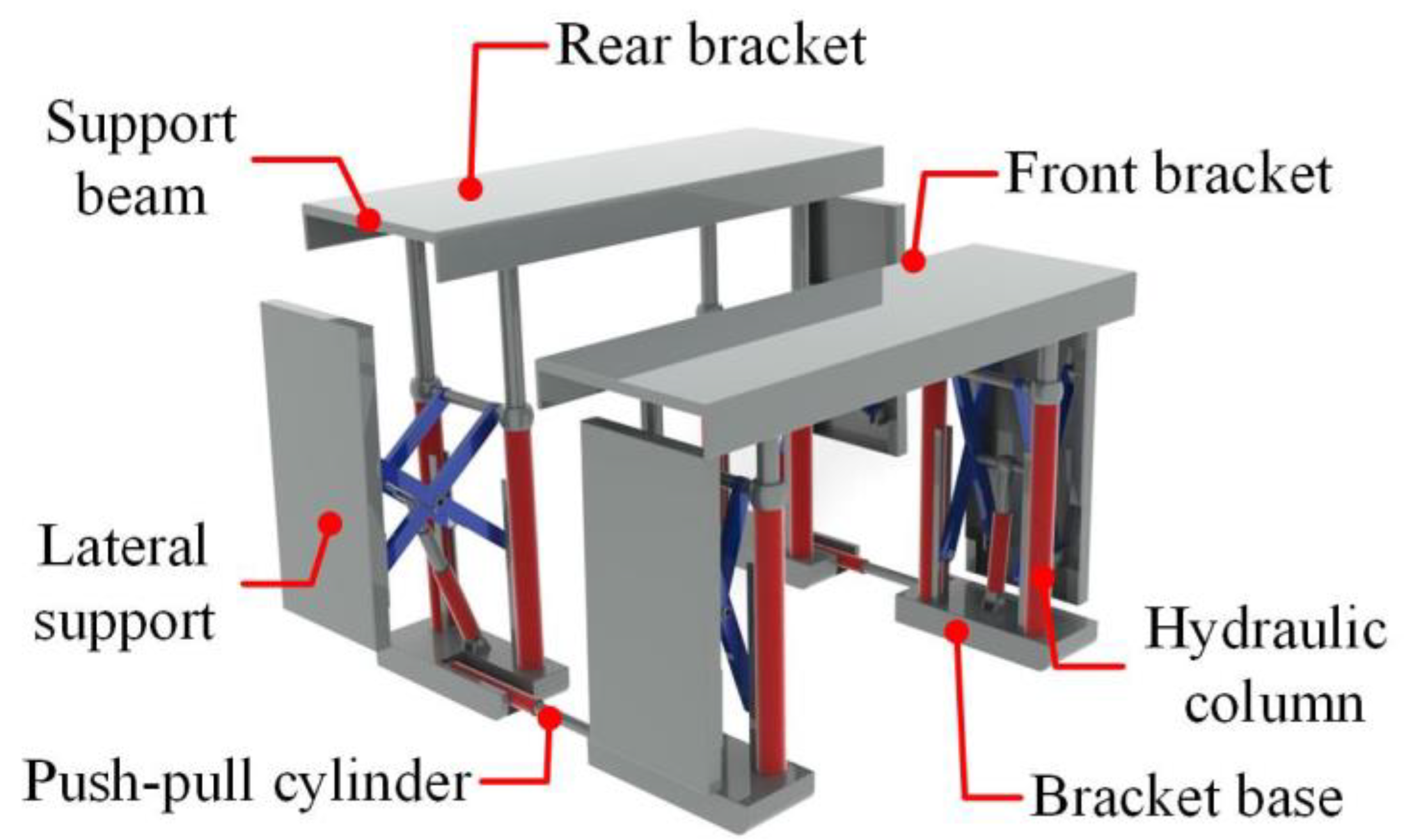
The twin-link multiple sets of stepping temporary support units consist of front and rear four-column hydraulic support units. These units include twin-link configurations, where two individual supports are connected as one group using shifting devices. The system also incorporates multiple sets of support units, allowing for the coverage of the temporary support area based on the required length of support. The stepping feature enables self-movement driven by hydraulic push–pull devices. Shifting cylinders connect the two hydraulic support units, enabling automatic shifting during the temporary support process. The twin-link multiple sets of stepping temporary support offer excellent stability and slip resistance, capable of fulfilling operational demands in roadways inclined up to 15 degrees. The design and structure of the twin-link stepping temporary support bracket are illustrated in
Figure 2.
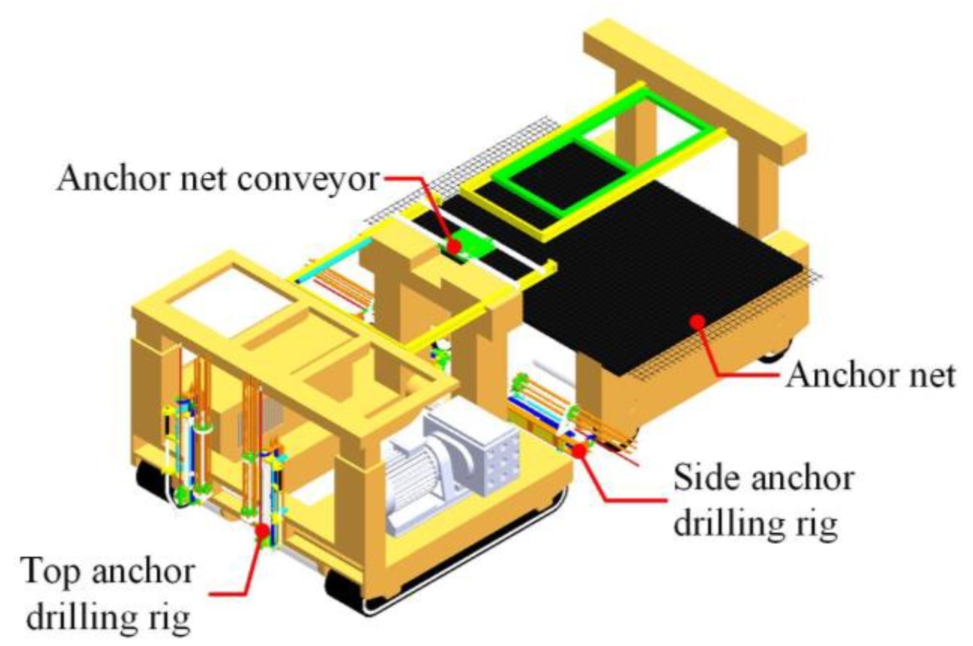
The drilling and anchoring vehicle is a tracked construction vehicle with a double-row four-arm drilling system, as shown in
Figure 3. The system consists of a mesh laying unit and a drilling and anchoring unit. The mesh laying unit is responsible for laying anchor nets on the exposed coal-rock surface in front of the temporary support units, forming a preliminary anchor support.
2.2. The Principle of the Parallel Process for Excavation and Support Anchoring Based on the Twin-Link Stepping Temporary Support
The construction unit establishes a temporary support zone at the face of the excavation roadway based on the twin-link stepping temporary support system. This innovation introduces a parallel operation process that encompasses excavation, temporary support, drilling, and anchoring. The primary objective of this process is to effectively utilize roadway space and streamline construction sequencing, resulting in reduced support sequence time and accelerated excavation progress. The parallel process operates as follows: the roadheader positioned at the forefront of the coal roadway performs slotting and section-cutting operations, while the twin-link stepping temporary support system advances with the roadway face to create a temporary support zone. The drilling and anchoring machine, located behind the temporary support zone, carries out permanent anchoring.
The steps for implementing the parallel process of excavation, support, and anchoring are as follows:
(1) Excavation and coal transportation by roadheader: Following the adjustment of the cantilever roadheader’s position, the roadheader integrates the rotation of the cutting arm with the height rotation of the cutting head to efficiently perform coal cutting.
(2) Forward movement of the twin-link temporary support system: After the roadheader advances, the hydraulic columns of the front bracket of the temporary support system retract, causing the roof beam to descend and detach from the roadway roof. The advance jacks extend, utilizing the friction generated by the rear bracket support to drive the front bracket forward. Upon reaching the support position, the hydraulic columns extend, allowing the roof beam to rise and reconnect with the roadway roof. The second stage is the movement of the rear bracket, a process similar to that of the front bracket.
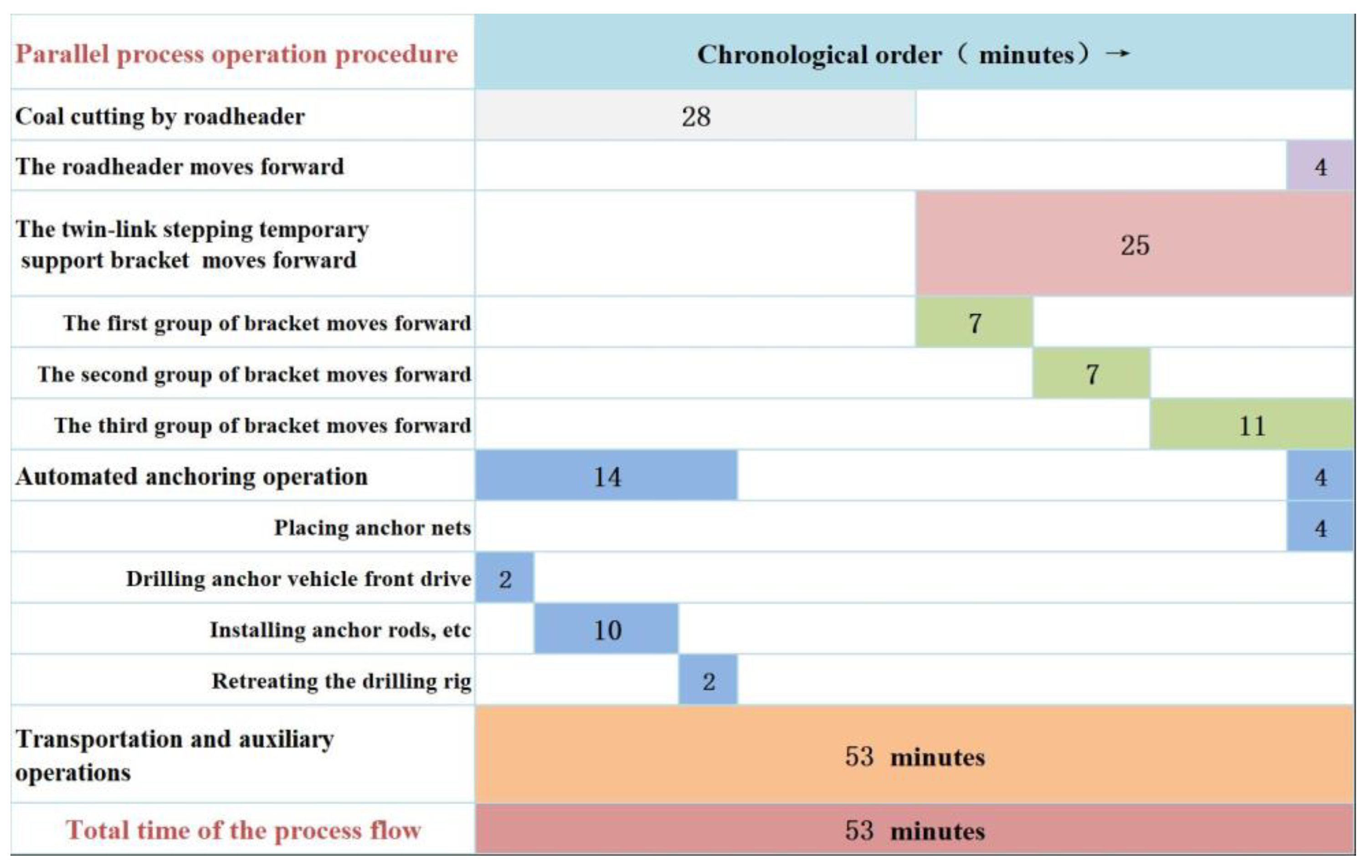
(3) Permanent anchoring: The drilling and anchoring vehicle performs the anchor protection process, involving automated drilling of anchor holes in the roof beam and side supports, filling them with anchor adhesive, installing anchor rods, and securing anchor cables. The chronological order of the steps within the operation process is presented in
Figure 4.
2.3. Comparison of Construction Techniques
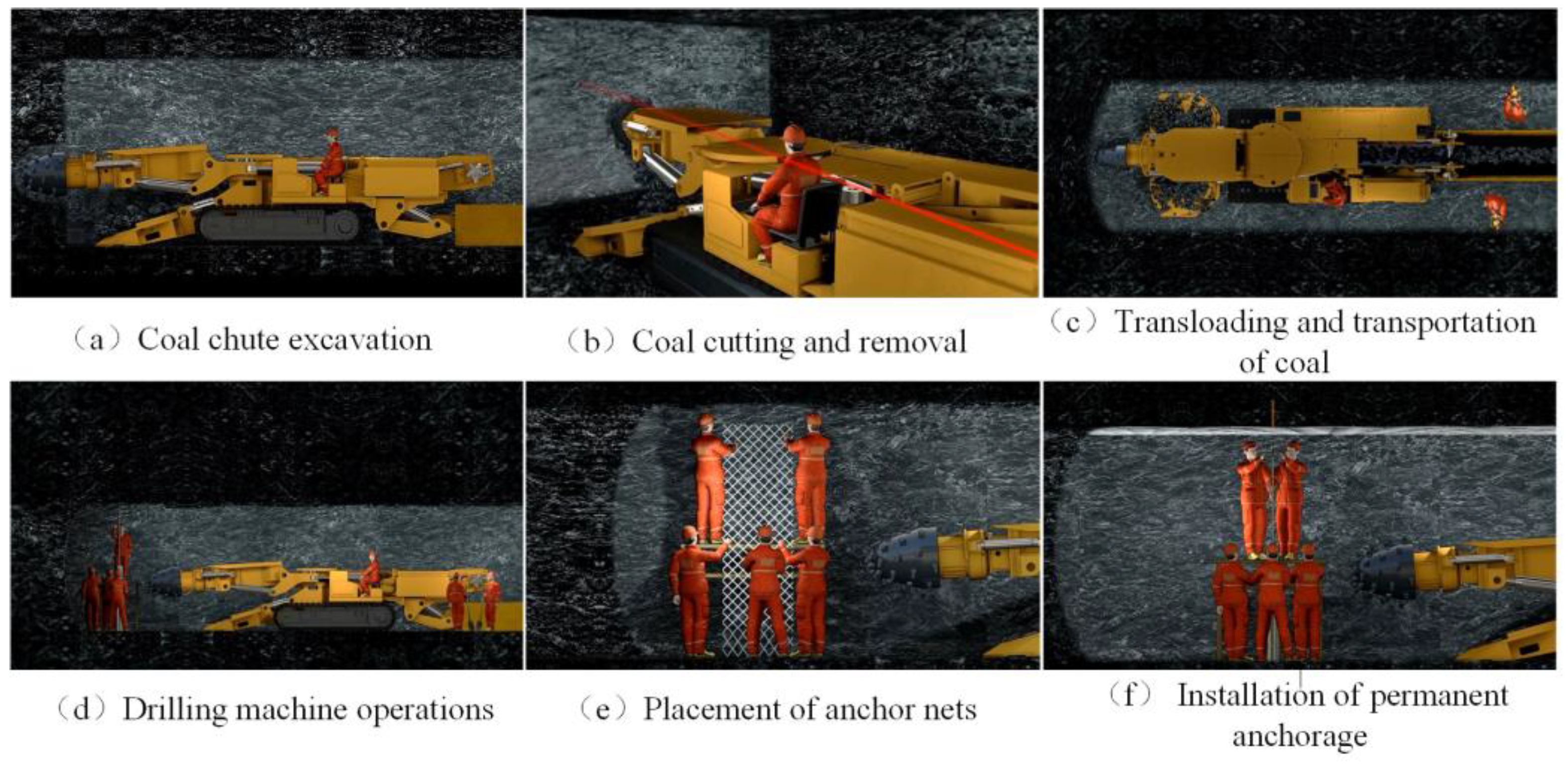
Due to the complex conditions in underground operations, a significant portion of comprehensive excavation tunnel construction currently depends heavily on manual labor for serial operations. The process primarily comprises six key steps: mobilization of excavation, cutting and removal of coal, loading and transportation of coal, installation of anchor nets, and pre-tensioning of anchor rods. The schematic diagram illustrating the traditional serial operations for comprehensive excavation roadways can be seen in
Figure 5.
In the conventional sequential operation process, the tunneling machine is required to retreat a specific distance after advancing to ensure roof control. Support workers utilize single anchor rod drilling machines to offer temporary or permanent anchor support in the face area. Tunnelling and anchor support activities must take turns and cannot be conducted simultaneously in the sequential operation mode. Due to the inaccessibility of the tunnel face by the drilling and anchoring vehicle, manual anchor support takes a considerable amount of time, resulting in low efficiency. Furthermore, during manual support operations, if the roof falls and there are currently no effective means to protect miners’ safety, it poses a significant threat to their lives.
In comparison to the traditional process, this paper presents a novel excavation-support-anchor technique named the twin-link stepping temporary support, which operates in parallel. The excavation area is partitioned into three zones: tunneling, temporary support, and permanent support. The temporary support function acts as a bridge, connecting the spatial aspects of excavation and permanent support activities. This enables the simultaneous and non-interfering progression of tunneling and permanent support work, ensuring a high level of operational coordination. Additionally, in the event of a roof fall, the duplex stepped temporary support can employ a safety relief valve to gradually release pressure, ensuring that the roadway does not experience abrupt collapse.
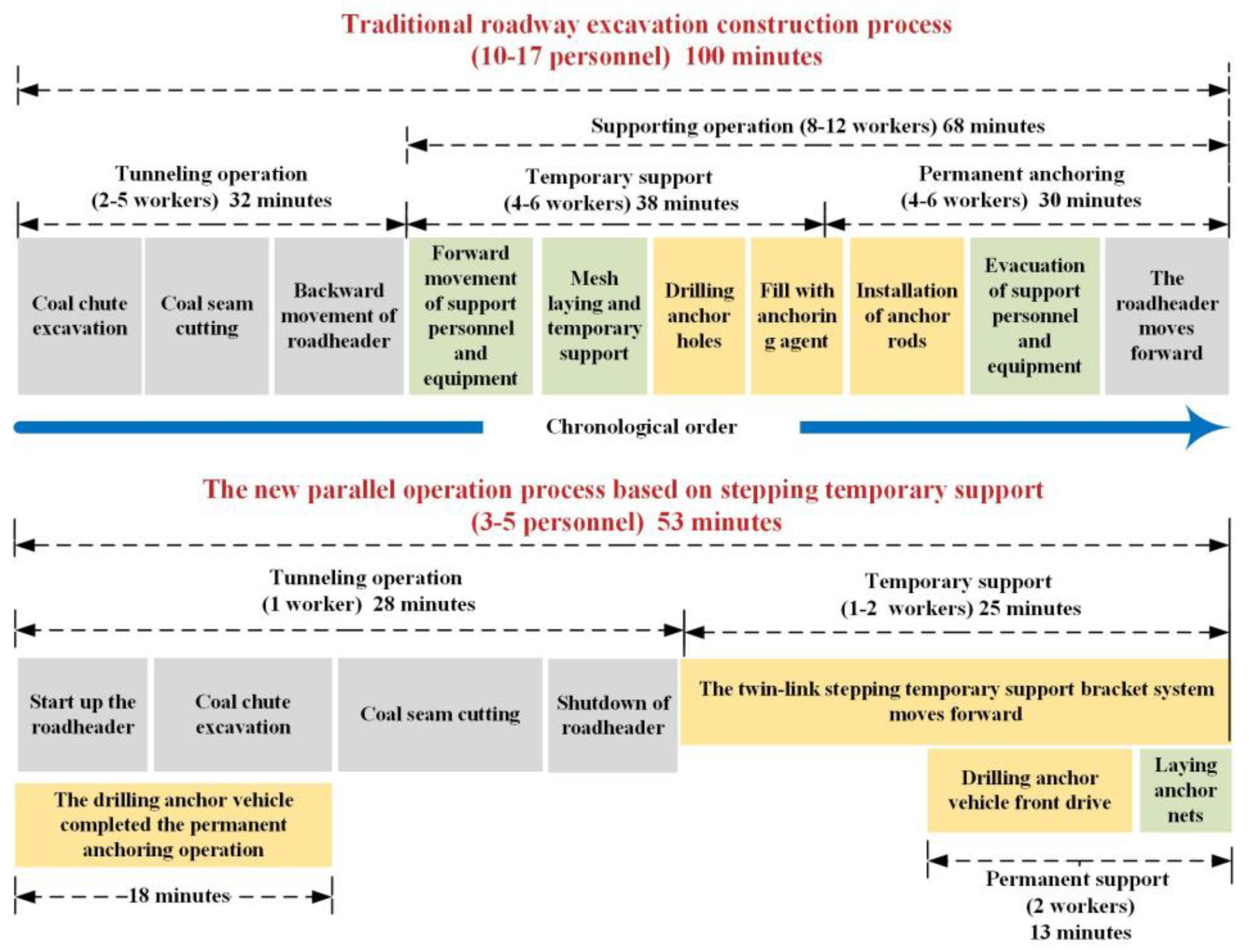
The new parallel excavation-support-anchor technique incorporates highly automated excavation, support, and anchoring equipment. Through parallel operations, it enables intelligent utilization of the six principal construction process equipment in comprehensive excavation roadways, resulting in increased excavation speed and reduced personnel involvement.
Figure 6 illustrates the comparison of time efficiency between the parallel excavation-support-anchor technique and conventional excavation construction methods. The ratio of time dedicated to excavation and support was reduced from the original 1:2.1 to 1:0.89, leading to an almost threefold improvement in support efficiency. The overall efficiency of excavation and support can be enhanced by approximately twofold. By following a collaborative parallel operation approach of “support ahead and anchor behind” during excavation, the parallel excavation-support-anchor construction technology significantly reduces the likelihood of roof cave-ins and rib accidents in coal mines, thereby enhancing mining efficiency.
The twin-link stepping temporary support system designed in this paper significantly enhances the safety and efficiency of the excavation work face. However, during the advancement of the roadheader and the movement of the twin-link stepping temporary support unit towards the excavation face, the support in the same roof area must be repeatedly removed and repositioned. This repetitive support activity during the movement process can potentially exacerbate hazards such as roof collapse, delamination, and roof fall, particularly if the roof stability is compromised. Therefore, ensuring a certain level of roof stability is crucial for the effectiveness of the stepping temporary support method. In order to address these concerns, this study employs a numerical simulation approach to establish a computational model for excavating and repeatedly supporting the tunnel roof using the stepping temporary support method. The aim is to investigate the conditions under which the repeatable roof support is feasible in different working scenarios. This research will provide critical insights into the suitable conditions for applying the stepping temporary support system in roadway roof management.
3. Establishment of Numerical Model for Surrounding Rock of Roadway Excavation
3.1. Composition of Surrounding Rock Structure in Roadway Excavation
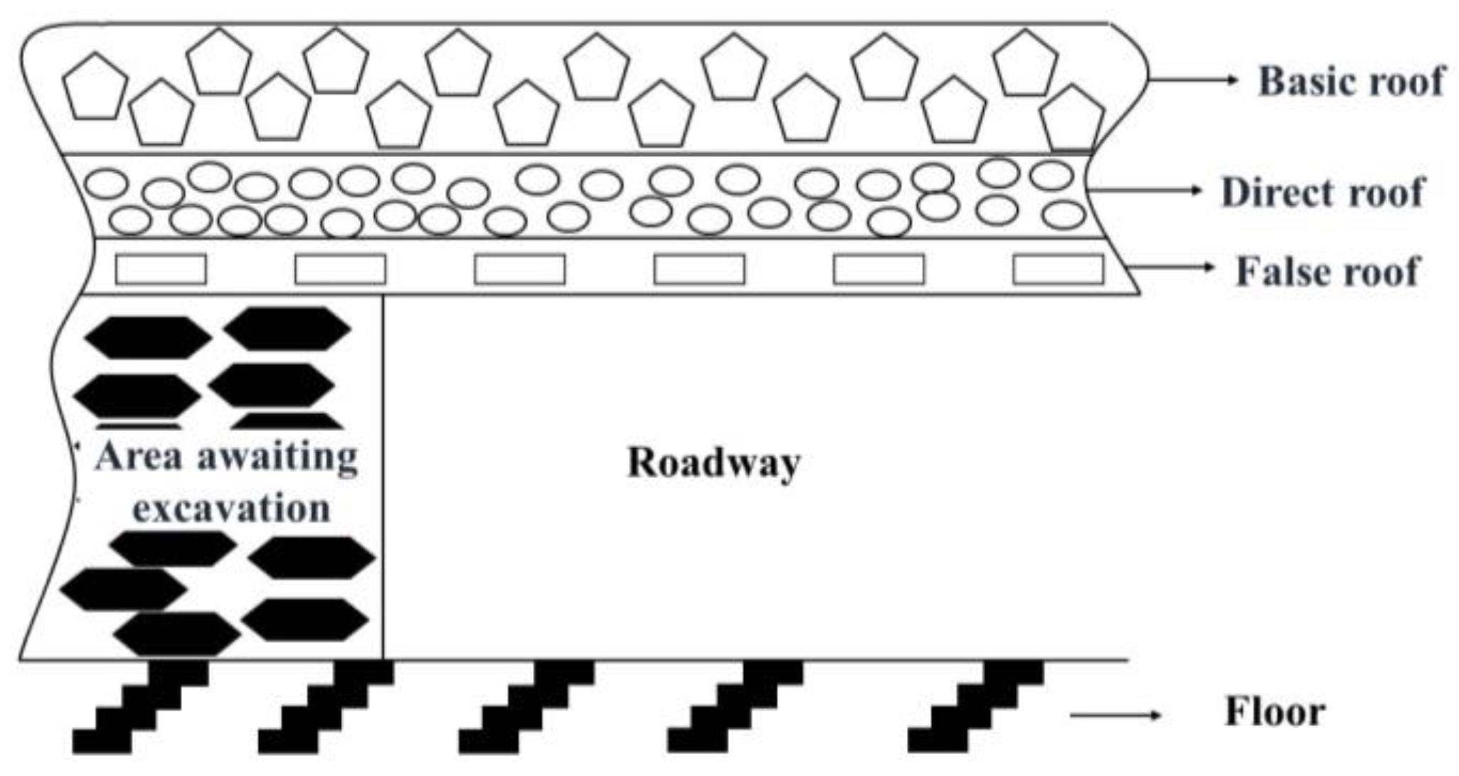
Generally, rock layers are present above the coal seam within the roadway. These rock layers possess different properties and thicknesses, which significantly impact the stability of the roof formed by these layers. The roadway roof is categorized into three sections: the basic roof, the direct roof, and the false roof [
16]. The composition of the surrounding rock structure in the roadway is illustrated in
Figure 7.
(1) The basic roof is generally located above the direct roof, but if there is no direct roof, it directly overlays the roadway and coal seam. This rock layer exhibits good stability due to its thickness and hardness.
(2) The direct roof is usually positioned above the false roof. In the absence of a false roof, it directly overlays the roadway and coal seam. The thickness of the direct roof is typically greater than 0.8 m and is mainly composed of sandstone, Sandy mudstone, or mudstone. Its stability is generally acceptable. If the thickness of the direct roof is less than 0.8 m, in order to ensure roadway safety, the use of stepped temporary support technology and equipment should be avoided.
(3) A false roof may exist in certain coal seams, typically constituted of relatively fragmented mudstone. The thickness of the false roof is usually between 0.3–0.8 m, rendering it unstable. In the presence of a false roof, the implementation of stepped temporary support technology and equipment should be avoided.
(4) The roadway floor can be classified as either a direct floor or basic floor. However, the impact of temporary support on the roadway floor is negligible. Consequently, when establishing a numerical model for the roadway, the roadway floor is simplified to a single lithology.
According to the stress formation mechanism in roadway excavation, the surrounding rock of the advancing roadway experiences gradual damage from shallow to deep. During the initial period after excavation, the direct roof of the roadway is primarily prone to destruction. Simultaneously, temporary support serves the purpose of preventing roof collapse and excessive settlement of the direct roof, with limited influence on the deeper surrounding rock. Hence, the direct roof plays a crucial role in controlling the stability of the fully mechanized roadway.
3.2. Construction of Numerical Models
The 3DEC software is a three-dimensional numerical modeling program that utilizes the discrete analysis method. It enables the simulation of the response of discrete blocks, such as jointed rock masses, under both static and dynamic loads. Consequently, 3DEC can effectively simulate processes including block separation, rotation, and collapse, and can establish contact with and perform mechanical calculations on new blocks after their collapse [
17,
18,
19]. The use of 3DEC (3 Dimension Distinct Element Code) software allows for a more intuitive study of the stability of the surrounding rock after roadway excavation and repeated support.
The numerical modeling of the advancing face was conducted using the Bonded Block Model (BBM) method with the 3DEC software. This approach involved simulating the surrounding rock through a collection of bonded tetrahedral elements, enabling the analysis of various processes, including fissure development, fragmentation, as well as stress and strain dynamics [
20,
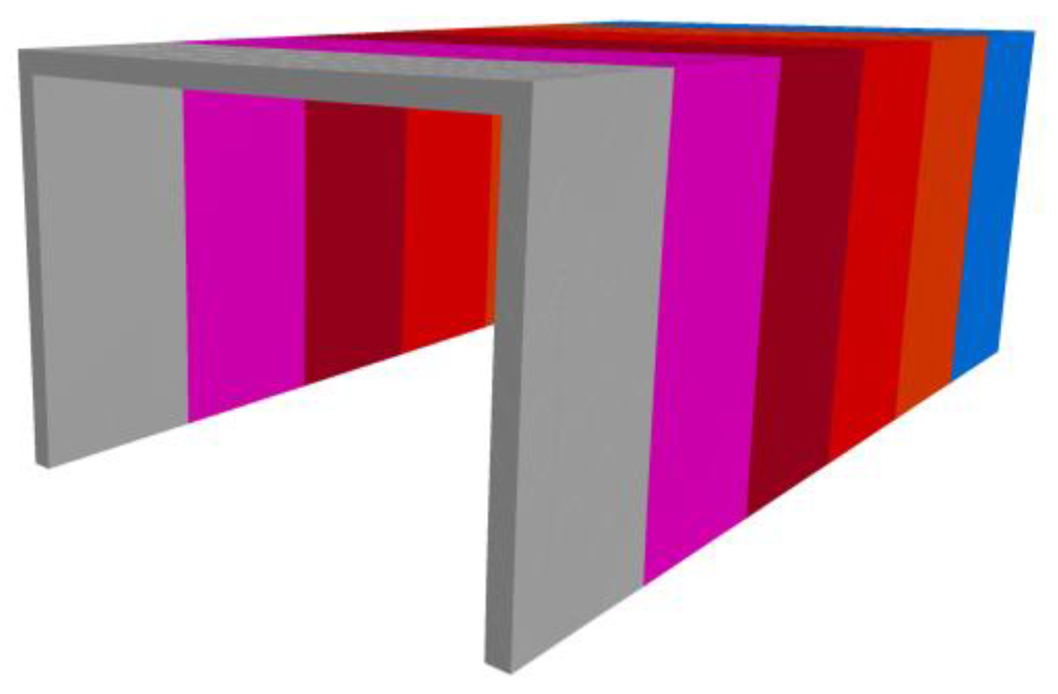
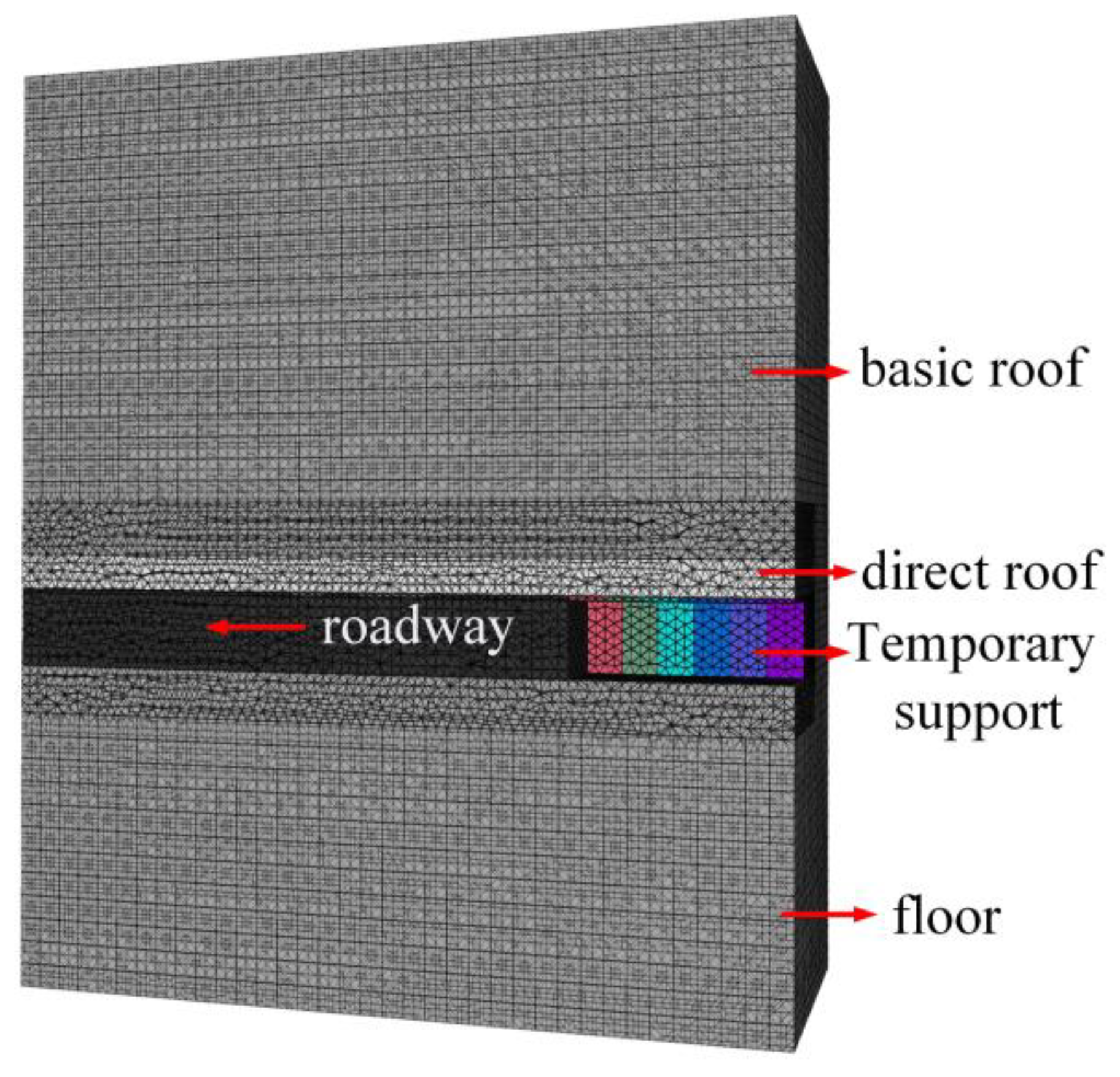
21]. The geological numerical model of the coalfield has dimensions of 36 m × 25 m × 46.6 m, with a rectangular tunnel section measuring 5.0 m in width and 3.6 m in height. Considering the stepping temporary support mechanism, the influence of the support system on the roadway bottom is minimal. Consequently, the established numerical model directly merges the floor with the basic floor to form the roadway bottom. The roadway roof comprises the direct roof and the basic roof, with a coal seam thickness of 5 m. The direct roof is positioned above the excavated coal seam, while the upper part of the direct roof represents the basic roof. Coulomb sliding is employed to model the contact types between internal constitutive blocks within rock formations and between distinct rock formations in numerical simulations. The numerical model is visually depicted in
Figure 8.
The direct roof plays a crucial role in controlling the surrounding rock of the comprehensive excavation roadway. This study aims to investigate the stability of the direct roof under stepped temporary support, and evaluate the applicability of this support method through numerical simulations. By varying the thickness and mechanical parameters of the direct roof, as well as the roadway depth, different roof conditions are considered. The repeated supporting process of the stepped temporary support has minimal impact on the basic roof, floor, and coal seam of the roadway. Consequently, the basic roof and bottom plate of the roadway are considered non-control variables. The geological conditions are set as relatively hard sandstone and sandy mudstone, which remain constant throughout the numerical simulation.
The model consists of individual blocks, each with a side length of 0.3 m, resulting in a total of approximately 1.55 million three-dimensional elements. To achieve a gradual mesh transition from the center to the outer side, a gradual mesh refinement approach is applied from the roof and bottom towards the center. Fixed boundary conditions are imposed on the left and right, front and back sides, as well as the bottom of the model to restrict horizontal and vertical displacements. A vertical downward load is applied to the roof of the model to simulate the self-weight stress generated by the overlying rock layer. Varying the roof loads allows for simulating the stability of the excavation roof at different depths of the roadway.
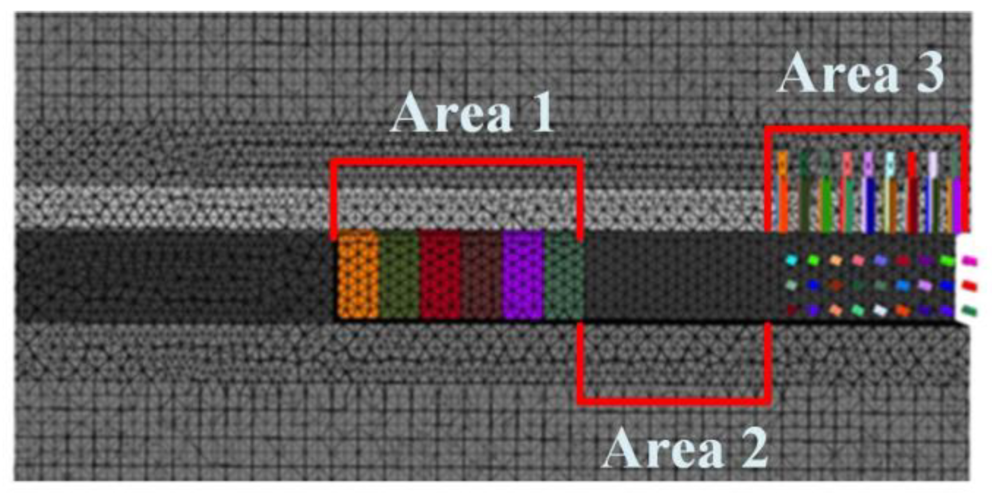
During the excavation, support, and anchoring equipment processes, the cantilever shearer has a length of approximately 8–10 m, and each set of twin-link temporary support units has a width of 3.2 m. Therefore, three sets of twin-link temporary support units are used to form a temporary support zone above the shearer, creating a tunnel temporary support area. A support model is established in the 3DEC software as depicted in
Figure 9. Due to constraints in the numerical modeling of the support system, only the framework structure of the supports is retained, and transitional devices that do not impact the roof are removed. Considering the absence of crushing or similar occurrences in the normal operating condition of the support, as well as the metal being in the elastic phase, the support is presumed to be rigid, while the surrounding rock is considered a deformable body that has not yet met the Mohr–Coulomb criterion. Consequently, elastic contact is established between the support and the surrounding rock.
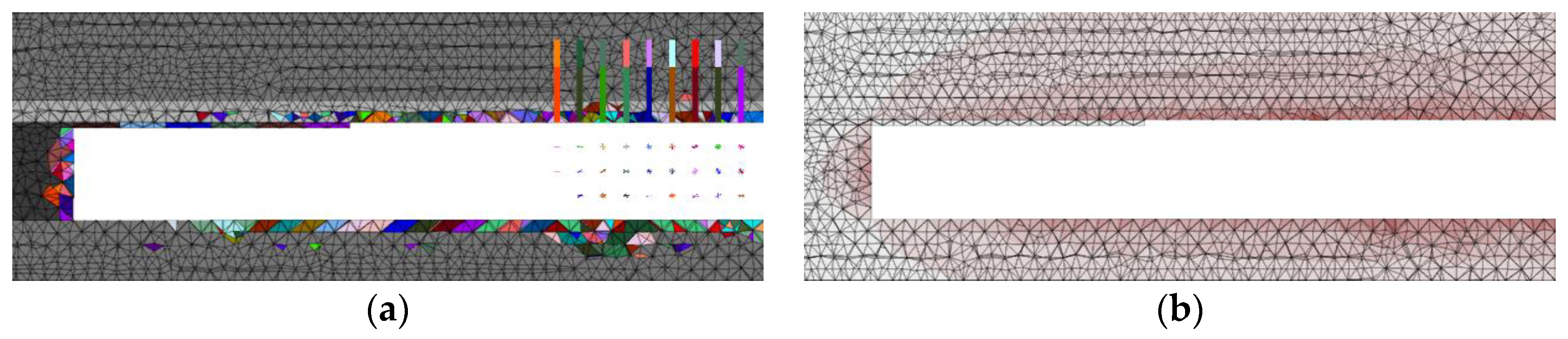
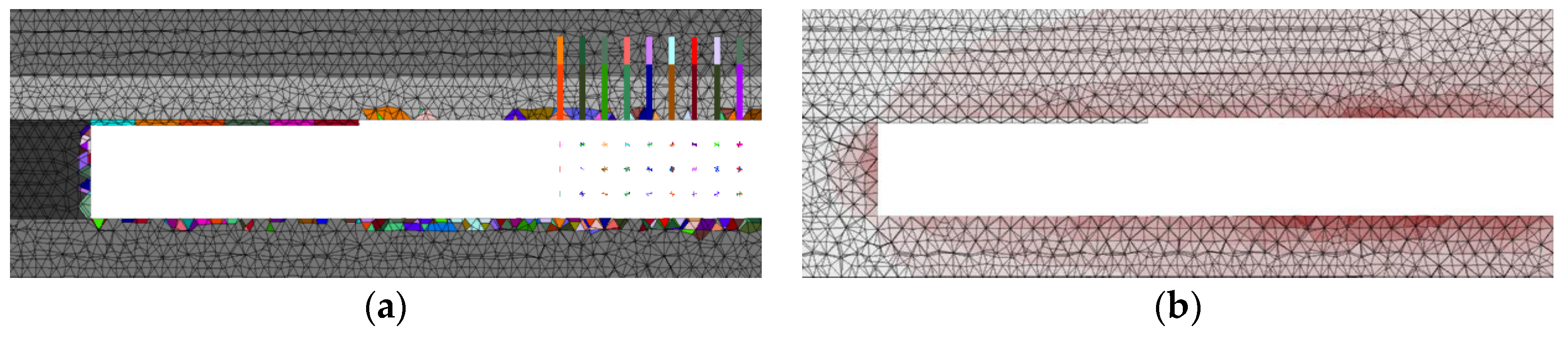
The excavation process in the numerical simulation involves stepwise excavation of the roadway and stepwise support, with each step being 1.6 m. Following each step of roadway excavation, the original rock stress is applied to the surrounding rock of the excavation face and gradually reduced to mimic the process of stress release in the field after excavation. The stress release is represented by a power exponential equation, with a rapid initial release followed by a slower release in later stages. Temporary bracing is implemented when the released stress reaches 70% of the original rock stress after each excavation step, to provide support to the surrounding rock. For the first six excavation steps, a monolithic brace is added at each step. Upon completion of these initial six steps, the numerical model forms a complete temporary support area for the roadway. The coupled model of the first six excavation steps and the temporary support is depicted in
Figure 10.
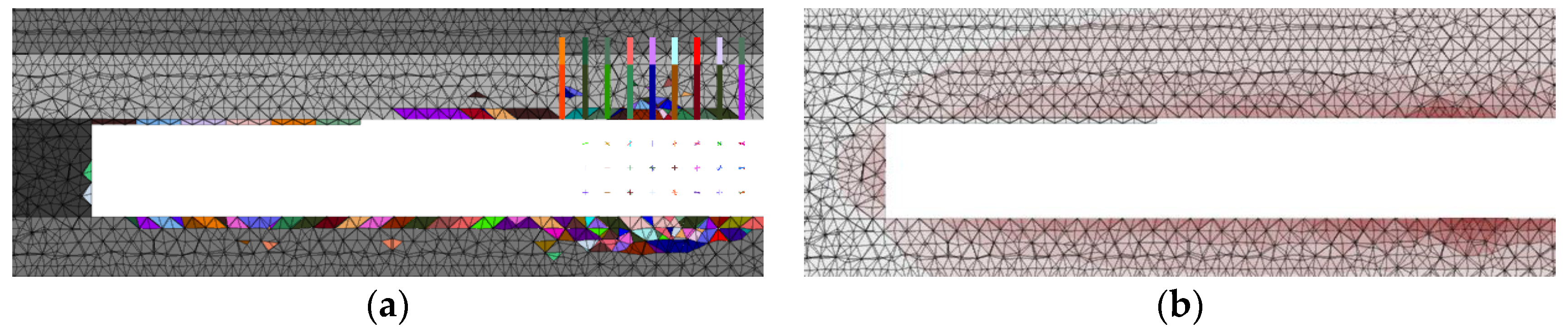
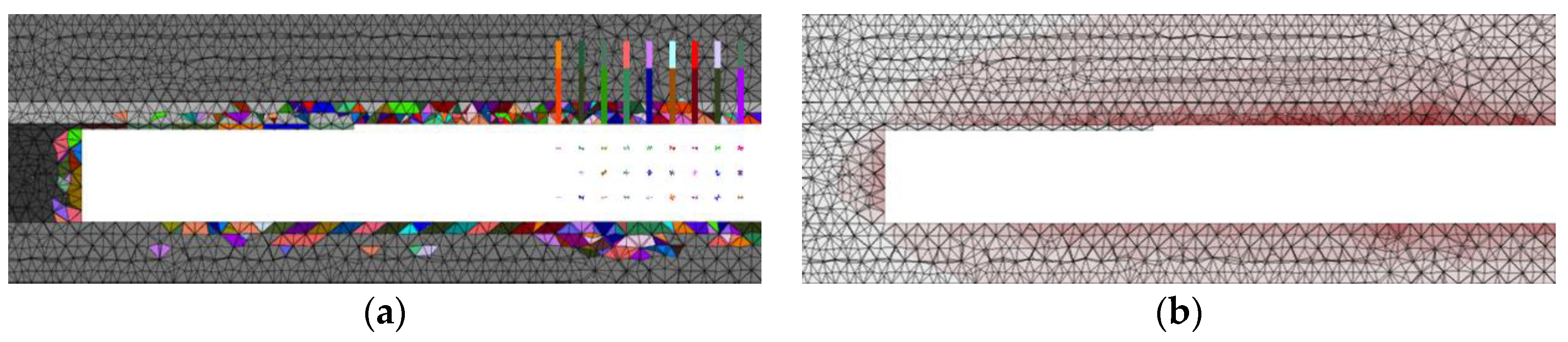
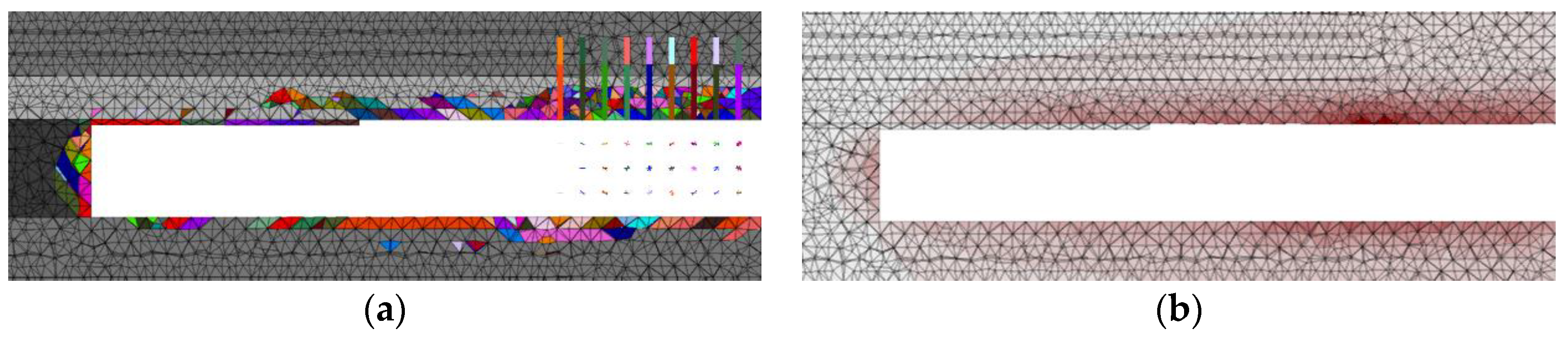
In the subsequent excavation sequence, a sequential movement of six monolithic braces in the excavation direction is employed for each excavation step, simulating a stepping repetitive support process for the roof slab. This results in the formation of an empty roof zone after the forward movement of the 6th brace. Once the stress in the hollow roof area is released to 30% of the original rock stress, the permanent support of anchor rods and anchor cables begins. The anchor rods and anchor cables were simulated using the Cable structural unit integrated in 3DEC software. The anchor rod has a diameter of 22 mm and a length of 2.4 m, while the anchor cable has a diameter of 17.8 mm and a length of 6 m. The spacing between the roof anchor rods is 1 m, with six rods per row and a spacing of 0.9 m. All anchor rods are arranged vertically against the roof. The spacing between the two wall anchor rods is 1 m, with four rods per row and a spacing of 1.1 m. They are all arranged vertically against the walls. The spacing between the roof anchor cables is 1.8 m, with a row spacing of 2 m. All of them are arranged vertically against the roof of the roadway.
The numerical simulation process involved digging a total of 12 excavation steps, resulting in a roadway length of 19.2 m. This created a temporary support area of 9.6 m, an anchored area of 6.4 m, and a permanent support area of 6.4 m. Several displacement and stress monitoring points were strategically placed on the roadway roof at 1 m intervals to observe the numerical variations in roof plate stresses and displacements. Once the excavation was completed, the coupled numerical model of temporary support and permanent support was illustrated in
Figure 11.
The 3DEC model constructed in this paper utilizes the Moore–Cullen tensile damage criterion. The principal stresses in the three directions are denoted as
σ1,
σ2, and
σ3, and they are interrelated according to the following equation [
21]:
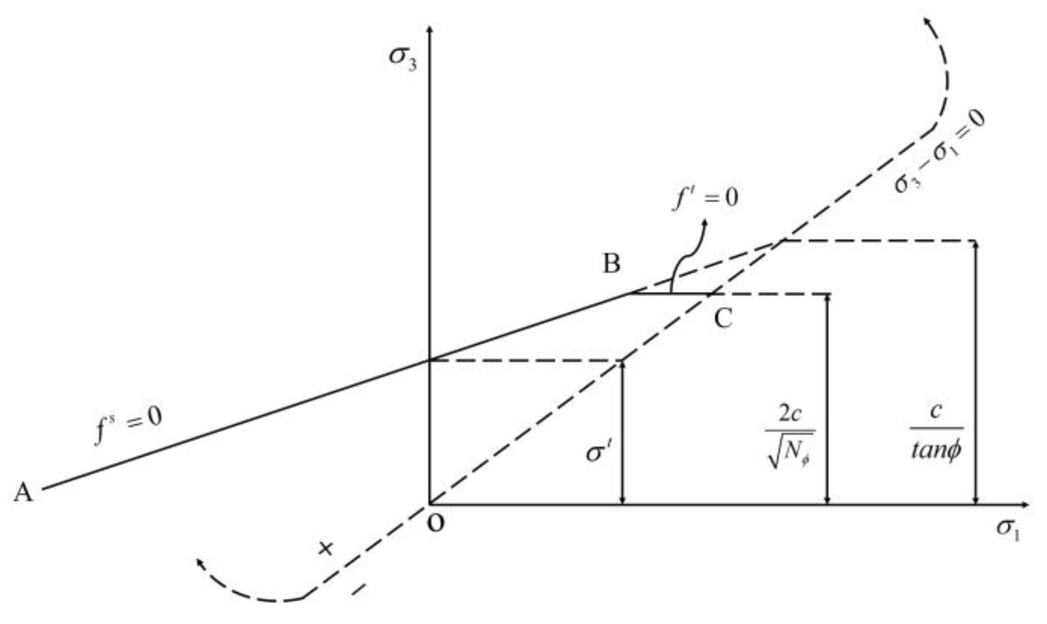
A schematic diagram illustrating the damage criterion represented by the stress values (
σ1,
σ3) is presented in
Figure 12. The damage envelope, denoted by
, is defined by the Mohr–Coulomb damage criterion
from point A to point B, and by the tensile damage criterion
from point B to point C. Where,
c-viscous cohesion;
σt-tensile strength;
∅-friction angle.
The parameters that play a significant role in determining the perimeter rock damage for numerical simulation are cohesion, friction angle, and tensile strength. These criteria are assigned to the numerical model. The displacements of the side and bottom surfaces of the model are fixed, while other initial, boundary, and operational conditions are defined. The model is then meshed and subjected to numerical calculations.
6. Conclusions
This paper presents a twin-link stepping temporary support process for underground coal mine excavation roadways and develops a comprehensive set of twin-link stepping temporary support equipment, enabling simultaneous operations of drivage, support, and anchoring in underground coal mines. A comparison was conducted to evaluate the temporal and spatial advantages of the new operation process in contrast to the traditional excavation process. The new process has demonstrated the potential to reduce the duration of a single excavation cycle by nearly 50%.
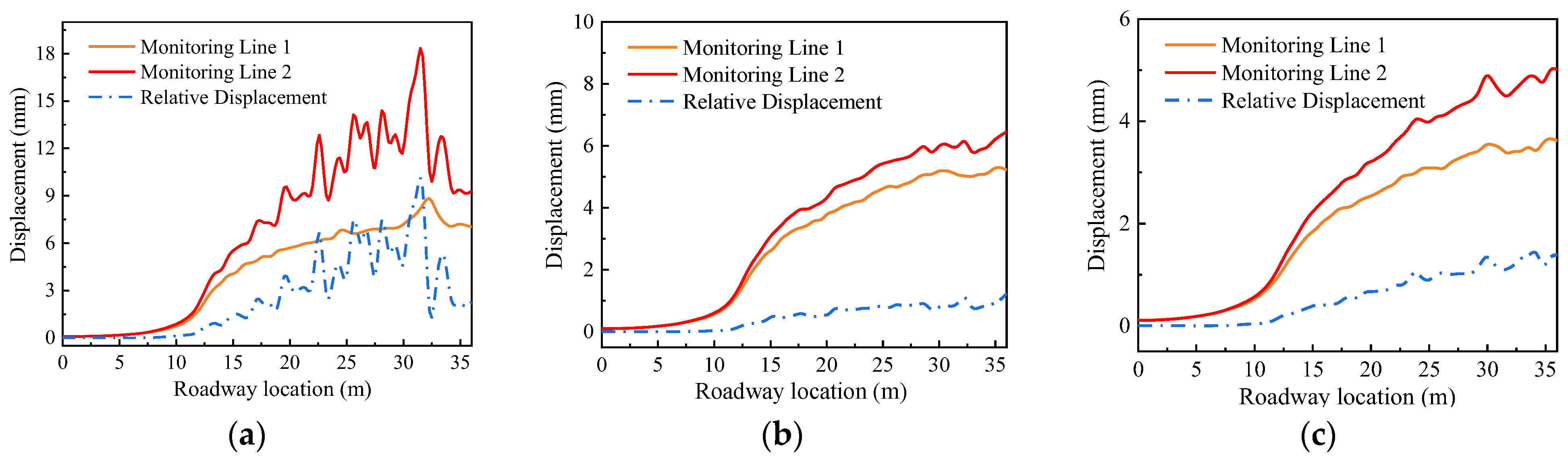
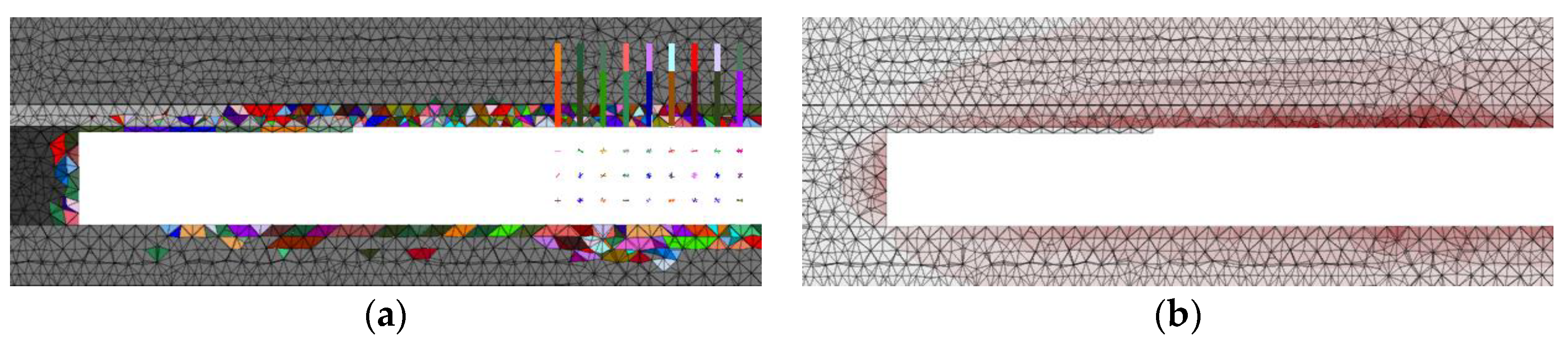
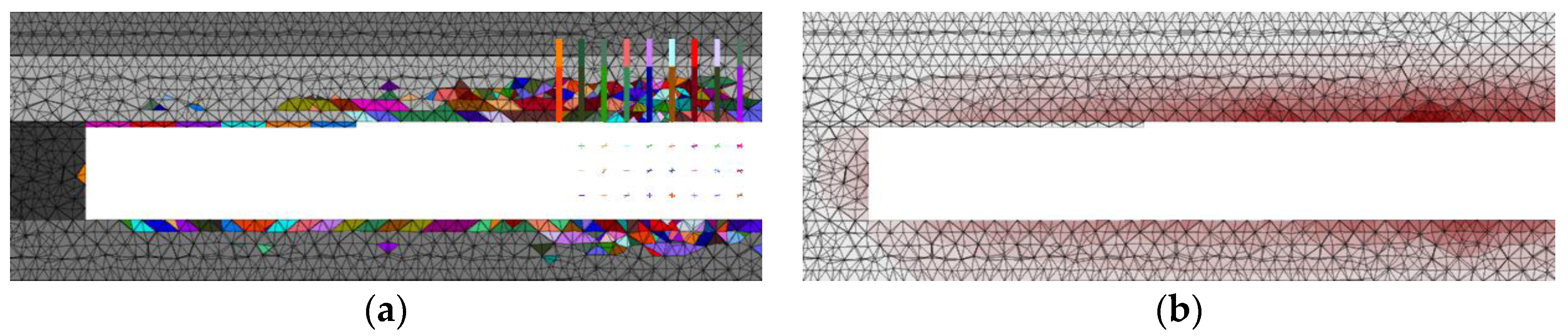
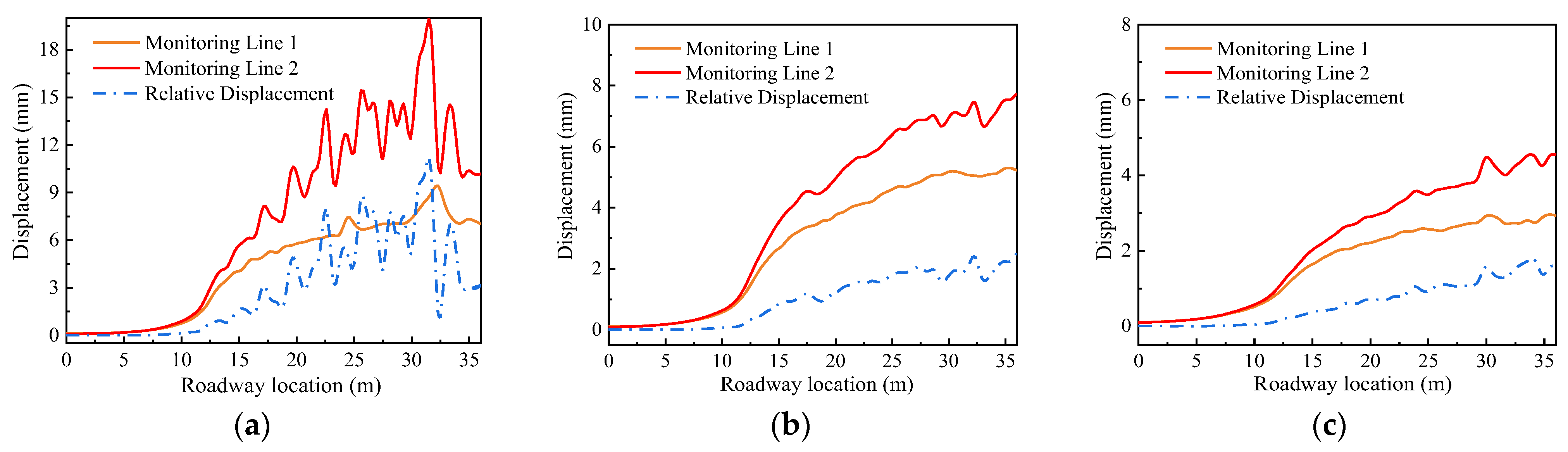
However, the repeated application of the twin-link stepping temporary support may potentially lead to roof damage in specific roadways, limiting its applicability. To address this, a numerical simulation approach using 3DEC was employed to establish a comprehensive numerical model for repeated support during roadway excavation. The numerical simulations were conducted considering various factors such as burial depths of roadways, lithologies of the direct roof, and thicknesses of the direct roof, based on the twin-link stepping temporary support process. By analyzing the fragmentation range, displacement, and relative displacement between the direct roof and the basic roof, the range of repeatable roof support for the roadways was determined. Consequently, this study provides the necessary conditions for the implementation of the complete equipment of the twin-link stepping temporary support system.
The proposed twin-link stepping temporary support process and the numerical simulation method for repeatable roof support in roadways address the significant deficiency of ineffective temporary support in underground excavation roadways, thereby greatly enhancing the safety and efficiency of underground coal mine excavation roadways. Furthermore, the new process, equipment, and research methods presented in this paper have the potential for application in similar operational roadways.


 ,
, 


