Featured Application
In the last two decades, there has been an upward trend in obtaining redundant strap-down inertial navigators of reduced size and weight, which can be used on small vehicles (miniaturized satellites, miniaturized space robots, space rovers, MAVs, UAVs) or on vehicles that require onboard equipment with such properties (satellites, launch vehicles, missiles, aircraft, robots used in various industrial applications). A special application of the here-proposed methodology is the estimation of small satellites’ attitude-based gyro measurements, providing, at the same time, a high degree of redundancy of the inertial detection unit.
Abstract
The significant technological changes related to the manufacturing of the miniaturized sensors produced a higher impact at the level of the detection units equipping the strap-down inertial navigation systems (INSs). Together with miniaturization, many more advantages are brought by these technologies, related to low costs, low necessary energy, high robustness and high potential for adapting the design solutions. However, reducing the dimensions and weight of the sensors is reflected by a decrease in their performance in terms of sensitivity, noise and the possibility of controlling sensitive elements. On the other hand, there is a permanent increase in the need to have in-space applications of miniaturized systems with a high degree of redundancy and to equip miniaturized satellites, miniaturized space robots or space rovers. The paper proposes a new methodology to increase the quality of the signals received from the miniaturized inertial measurement units (IMUs), but also to increase the degree of redundancy, by using low-cost sensors arranged in redundant linear configurations. The presentation is focused on the development of an attitude system based on strap-down inertial techniques which uses a redundant IMU equipped with three linear clusters of miniaturized gyros. For each of the three clusters, a data fusion mechanism based on the maximal ratio combining method is applied. This fusion mechanism reduces the noise power and bias of the signal delivered to the navigation processor. Shown are the theory, software modeling and experimentation results for the attitude algorithm, for the data fusion method, and for the integrated system.
1. Introduction
Available on the market for over three decades, modern navigation systems include inertial navigation systems (INSs) and satellite-based navigation systems such as global positioning systems (GPSs) as key positioning technologies in most of the developed applications. INS is a completely autonomous device for positioning and attitude estimation, which since the 1940s has established itself as an important component in navigation systems for military and civil applications, but it had a significant contribution that is also growing strongly in positioning and space navigation applications, especially due to this advantage offered by its autonomy. Actually, INSs are now found as standard components in the navigation systems that equip satellites, launch vehicles, space rovers, space robots, aircrafts, ships, and submarines, having the great quality to provide attitude, speed and position of the monitored vehicle with an adaptable higher rate and a very good short term performance [1,2,3]. A very interesting application of the INSs is the relative navigation of spacecraft vehicles, especially of small satellites, where these systems play a very important role in two configurations considered traditional for this kind of navigation: GNSS/INS and INS/vision-based synergic systems [4,5,6,7,8,9,10]. On the other hand, the literature, as well as the websites of the specialized companies producing equipment for navigation, reveals a lot of applications involving the use of INS in space applications [11,12,13,14,15,16,17,18]. For example, iXblue in partnership with Airbus Defence & Space designed and manufactured for over two decades the Astrix gyroscopes used in a lot of space applications, from low Earth orbit (LEO) to geostationary Earth orbit (GEO) and even Lagrange points [11]. Safran produces SPACENAUTE, an ultra-compact inertial measurement unit for space launchers, selected and qualified for the Ariane 6 European launcher [12]. Advanced Navigation in partnership with the Space Machines Company equipped Optimus (an orbital service vehicle (OSV) that will provide on-demand orbital services, such as repairing, refueling and upgrading space infrastructure) with a space-grade inertial navigation system (INS) called Boreas X90; Optimus is expected to be launched from Vandenberg Space Force Base aboard a SpaceX Falcon 9 rocket [13]. Also, the Australian Space Agency announced that, on the Moon to Mars initiative, Advanced Navigation in collaboration with Q+CTRL developed quantum-enhanced inertial navigation solutions for space launch vehicles, satellites, and landers. This new inertial navigation technology will be an important element in the Artemis Lunar Exploration Program of NASA [14,15,16].
Fully benefiting from the advantage of its total autonomy, but also from the complementary with the GPS system or with other navigation systems, INS was maintained as an indispensable component of the navigation systems and was strongly developed in trend with the new technologies in the fields of the inertial sensors and of the computing equipment with boarding capabilities on various aerospace systems. Therefore, the INS structure has changed over time, passing from the gimbaled INS to strap-down INS (SDINS), and currently aims more and more at low-cost and small-size structures, sometimes packaged with GPS receivers for everyday use such as phone/vehicle location, asset tracking and even new applications such as simultaneous location and mapping [19]. An important current application of these low-cost and small-size structures SDINS is the attitude evaluation of spacecraft, with a special impact on the small satellites’ attitude control. In this kind of application, an important role is played by the first calculation floor of a classic SDINS component, the floor that allows attitude determination, which uses IMUs based especially on the gyroscopic component. The provided attitude solution is then fused with the solutions provided by other complementary systems on board the satellite, astro-observers (sun sensors, horizon sensors, star sensors, Earth sensors), and magnetometers, each of these having their own advantages and limitations [20]. The literature reveals a lot of applications for the development of attitude determination and control system (ADCS) equipping pico-satellites [21], nano-satellites [22,23,24,25], and micro-satellites [26,27,28] by using inertial techniques. Another perspective for a complementary system for attitude evaluation was opened by the architecture of GOMX-4A and GOMX-4B nano-satellites launched in the GOMX-4 mission of GomSpace from Denmark [29]. Starting from this architecture, a new attitude estimation solution was proposed, integrating the Automatic Dependent Surveillance-Broadcast (ADS-B) receiver and MEMS gyro by using a multiplicative extended Kalman filter (MEKF) [30].
Related to the attitude detection and control system (ADCS) for small satellites, it supposes the presence of a detection system able to measure/estimate vehicle angular orientation, an actuation system able to generate torques to change the angular position of the vehicle, and a control system that includes some algorithms, which control the actuation system based on the current attitude data provided by the detection system and on the desired attitude data. The attitude sensors included by the detection system can be of two types: (1) relative attitude sensors, which need an initialization of the attitude information to be able to estimate the current attitude (gyroscopes and IMUs); (2) absolute attitude sensors, which use various objects or phenomena outside the satellite to determine the attitude (sun sensors, horizon sensors, star sensors, magnetometers, GPS, etc) [20,31,32,33,34,35]. The literature shows that there are some issues that need to be overcome at the level of the sensors in the small satellite attitude determination systems: (1) the impossibility of having the full attitude solution from all sensors; (2) the exchange of light and the eclipse, which produces intermittences in providing the attitude data by star and sun sensors; (3) the limited accuracy of some sensors (i.e., the magnetometers, based on the measurement of the Earth magnetic field, which has an accuracy no better than 1 deg); (4) the very low available space which limits the redundancy; and also (5) the accuracy in the use of performing architectures, which need special geometries (i.e., in certain situations, the use of a multi-antenna GPS receiver able to produce an accurate attitude solution) [20,26]. The horizon sensors are used to measure roll and pitch angles, as they are not able to provide the yaw angle, while the sun and star sensors offer directions. Because the star sensors and sun sensors are not able to offer continuous attitude data, many architectures have added an IMU to provide attitude data between the valid measurements of the other sensors. From a different perspective, the inertial sensors in IMU are affected by various errors and they need to be corrected starting from the valid data delivered in the system by the complementary attitude sensors [35]. All these shortcomings led to the conception of attitude determination methods, which combine the data from the sensors included in the detection unit. From the point of view of these methods, the literature reveals the existence of two categories: (1) static methods, which offer a deterministic approach in solving the attitude determination problem, being independent of time (it is considered that the measurements are made at the same time or at close time moments, between which the movement of the satellite can be neglected or can be easily compensated); and (2) dynamic methods, which are time-dependent, so they take into account the movement of the satellite, and offer a stochastic attitude estimation perspective, by accepting random noise as a disturbance to the measurement process, which implies the use of statistical filtering methods within the algorithms of data processing (for example, various variants of Kalman filtering) [34,36]. Among the static attitude methods, the following can be mentioned: the Triaxial Attitude Determination (TRIAD) method, Wahba’s problem, Devenport’s q-method, the Quaternion (QUEST) estimator method, and the Optimal Linear Attitude Estimator (OLAE) method [36,37]. Also, the studies exposed in the literature provide as dynamic attitude estimation methods the next ones: Kalman filter (KF), linearized Kalman filter (LKF), extended Kalman filter (EKF), minimal representation EKF, multiplicative EKF, additive EKF, backwards-smoothing EKF, deterministic EKF-like estimator, filter QUEST, extended QUEST, two-step attitude estimator, unscented filtering, particle filters, orthogonal attitude filter, predictive filtering, nonlinear observers, adaptive methods [36,38].
The current attitude solution determined/estimated by the detection system of the ADCS, based on the previously exposed methods, is further delivered to the control system of the ADCS, which, also based on the desired attitude information, controls the actuation system by using some control algorithms until the satellite will be oriented in the right angular position. The literature shows that this segment of the ADCS for small satellites is in continuous progress, and a lot of control algorithms are being developed, including ones based on linear control theory, but most of them are based on nonlinear control theory, such as sliding mode control [39,40,41], adaptive control [42,43,44], robust control [45,46], and other nonlinear control methods [47,48]. Also, fuzzy theory and neural network-based control algorithms are used and presented in the literature [42,49,50,51]. However, if we look at things from a practical side, all these control algorithms are designed based on the requirements imposed by particular attitude maneuvers of the satellites, which generated what was called attitude control modes: (1) detumbling control (after the separation from the launch vehicle); (2) gravity gradient control; (3) spin-stabilization control; and (4) pointing control (3-axis control: inertial, nadir, target, velocity direction, etc.) [34,35]. Therefore, all control algorithms come bundled with the type of actuation system used to control the attitude of the satellite: propulsive actuators (thrusters, solar sail), environment interacting actuators (gravity gradient actuators, magnetic torquers, moving mass control (MMC)) and angular momentum exchange actuators (reaction wheels, momentum wheels, control moment gyroscopes). Moreover, because of the various disadvantages of the used actuators, the single-actuator attitude control system configurations have their own limitations, and, as in the multi-sensor based attitude determination methods, have conceived and implemented multi-actuator attitude control systems for satellites, which use multi-actuators to ensure complementarity and redundancy [20].
The miniaturization technologies, like MEMS (micro-electro-mechanical systems) or NEMS (nano-electro-mechanical systems), are more and more applied in inertial sensors design and fabrication [52]. These manufacturing technologies have created inertial sensors that are smaller, low-cost and consume less power, but, at the same time, exhibit much larger errors than their higher-priced counterparts. As a consequence, the reduction in size of the detection units in INSs generates new challenges related to the improvement of their performance. Currently, the miniaturized IMUs performances are limited by the quality of gyro sensors related to the bias stability. Another major requirement for this kind of detection unit is low noise, the achievement of which is still an important issue [53,54].
Categorized as stochastic errors, the noises in inertial sensors comport two distinct components, known in the literature as long-term noise (low-frequency noise) and short-term noise (high-frequency noise) [1,55,56,57,58]. Additionally, some deterministic errors affect the miniaturized inertial sensors, but the research in the field provided various calibration methods that help to estimate and compensate for it [1,2,59,60,61,62,63]. For short-term noise filtering, the researchers tested various methods based on the wavelet transform [1,55,56,64,65,66,67]. A research team from the University of Putra in Malaysia used a Wavelet Multi-Resolution Algorithm (WMRA) to increase the performance of the low-cost inertial sensors in a MEMS IMU eliminating the short-term noise that parasitizes them. During the experimental tests, with an INS system including the MEMS IMU, different levels of decomposition and thresholding filters were evaluated; the final results provided a more accurate solution of navigation as a consequence of wavelet filtering [55]. In order to increase the accuracy of MEMS gyros, a de-noising mechanism using the second-generation wavelet transform was studied at Harbin Engineering University in China. Using the lifting scheme wavelet transform, the method proved an experimental reduction in the random drift error of a triaxial gyro MEMS [56].
A method to reduce the noise in MEMS gyros was proposed and experimentally demonstrated at the Chongqing University of Posts and Telecommunications, China. It was conceived as a combination between the FFT (fast Fourier transformation) noise reduction mechanism and the mechanism used in the simple wavelet noise reduction. The experimental tests proved an important noise reduction in the gyro data comparatively with the FFT noise reduction method [64].
Researchers from the University of California, Berkeley, proposed a multiple-model adaptive estimation to evaluate the magnitudes of noise variances in a gyro model, using the obtained values in an extended Kalman filter for a micro-satellite attitude estimation [27]. The numerical simulation and experimental data proved that the adaptive estimation of noise parameters improved the attitude estimation performance.
In a collaborative research, a Brazilian team from Instituto de Aeronáutica e Espaço and from Instituto Nacional de Pesquisa Espacial developed a calibration procedure for an IMU including four gyros in a tetrahedral configuration [65]. The wavelet analysis considered eight levels of decomposition, the filtering aiming at the removal of undesirable high-frequency noise components from the gyro signals; the procedure was experimentally tested and validated.
At the Key Laboratory of Micro-Inertial Instrument and Advanced Navigation Technology from Southeast University in Nanjing, a method using Kalman filtering was proposed for the online de-noising of the sensors data, while the results of the wavelet filtering were used as reference; the level of decomposition used for the Matlab wavelet function was 5 [66]. The conclusions underlined that the IMU measurement noise can be suppressed by the proposed Kalman filter and by the wavelet, while the filtering result obtained with the low-pass equiripple finite impulse response (FIR) filter was worse and there was a noticeable time delay when the tested IMU rotated [66].
Researchers from the School of Automation at the Beijing Institute of Technology developed a method to filter the MEMS gyro random drift. The experimental results obtained with a MEMS gyro showed that the method reduced the high-frequency noise, restrained the gyro random drift, decreased the mean square error and increased the signal-to-noise ratio [67].
Through these techniques, the short-term noise is substantially mitigated, limiting the band of the INS signals, which means optimal low-pass filtering. Unfortunately, they have several limitations in removing the long-term sensor noise, which still influences the performance characteristics of the INS for long-term signal processing; it may be mitigated or eliminated by using a complex navigator, obtained by integrating the INS with a navigation system based on another operating principle [68,69,70]. From another point of view, the long-term noise is situated in the band of 0 Hz to 100 Hz, together with the frequencies characterizing the vehicle’s dynamics, i.e., with the navigation useful signals measured by the sensors; as a consequence, direct filtering of this noise is not recommended and for its reduction, the data fusion algorithms from multiple sensors need to be applied. A first identified method estimates and removes the noise by fusing the INS data with another navigation system data (such as a GPS system) [2,71,72,73]. The procedure uses an INS error model, which takes into account the sensor’s noise; for example, the long-term noise component may be modeled by using random processes like random bias, random walk, Gauss–Markov, or periodic random processes [74]. Another method of reducing this noise is based on the data fusion between similar sensors in a redundant IMU, with sensors arranged in various configurations [69,73,75]. This redundant variant can be also improved with various algorithms for fault detection and isolation. Also, depending on the IMU redundant structure and the data fusion method used, this procedure may produce a reduction in both long-term and short-term components of the noise but also can bring some gains at the level of bias for the signal delivered to the navigation processor.
In terms of the IMU structures, the literature revealed several variants to use and to relatively arrange the sensors in order to detect all information necessary in obtaining the solution of navigation. Having in mind that the monitoring of a vehicle in 3D space requires information regarding the vehicle’s absolute acceleration and angular speed, it is necessary to have a minimum of six sensors in IMU, measuring the acceleration and angular speed components along three axes (six measurements).
The simplest and very well-known way to arrange the sensors in IMU is on two right rectangular trihedrals, one for gyros and another one for accelerometers; the two formed sensor triads need to have parallel axes one against the other [2].
Another possibility to arrange the sensors in IMU derived from the need to obtain a degree of redundancy in IMU, and generated a multitude of research studies related to the sensor’s optimal arrangement, also providing additional advantages represented by the possibility of detecting and isolating defects inside the IMU. The first study in this concern is attributed to Pejsa in 1974, but the theory was thorough in 1993 by Radix [75] and subsequently generated a lot of applications [76,77,78]; it stipulated that the sensor’s optimal arrangement can be obtained by orienting their axes of sensitivity in directions perpendicular to the lateral faces of some regular polyhedra (tetrahedron, cube, dodecahedron, icosahedron, etc.) or orienting their axes of sensitivity on several cones of revolution with a common axis of symmetry, at the intersection of these cones with half-planes delimited by this axis of symmetry, so that these axes of sensitivity form equal angles between them [75].
A third identified methodology to arrange the sensors in IMU starts from the classical arrangement but uses many detectors on the same axis, measuring the same quantity; it is called redundant linear configuration [69,73,79].
The work presented in the paper refers to a new method to increase the quality of the signals provided by the miniaturized IMUs by using low-cost sensors arranged in redundant linear configurations. The direct application of the here proposed methodology is the estimation of small satellites’ attitude-based gyro measurements. The main objective of the paper is to provide a method for the accuracy improvement of the three-axis attitude solution for small satellites, in terms of roll, pitch, and yaw angles, through the development of a small-size, low-cost gyro IMU, with a high degree of redundancy, equipping the detection unit of the ADCS, whose data are synergized on each detection axis by using a data fusion algorithm, which reduces the noise level, but also the bias values of the fused signals, which are finally used in a strap-down inertial attitude algorithm based on the quaternionic parameterization. Therefore, the exposure is focused on the development of the attitude system based on strap-down inertial techniques and quaternionic parameterization, which uses a redundant IMU with three linear clusters of miniaturized gyros (Figure 1), with the gyro data fused by using a mechanism based on the maximal ratio combining method. In the next sections are successively shown the mathematics in the back side of the attitude algorithm and of the data fusion algorithm, the software implementation and the results obtained through numerical simulation, but also the results achieved by testing the integrated redundant system with experimental data.
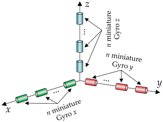
Figure 1.
Detection unit with three gyros clusters in redundant linear configurations.
2. The Attitude Algorithm
The proposed redundant attitude system aims to be used in the estimation of the attitude angles of the small satellites, monitoring in this way the attitude of the satellite towards an Earth frame. As general architecture, the attitude system can be organized as shown in Figure 2 and includes the following: (1) the redundant detection unit; (2) three data fusion blocks, which implement software with the same data fusion method; and (3) the attitude algorithm block which implements software the numerical processing procedures for the fused gyro data obtained from the three detection channels.
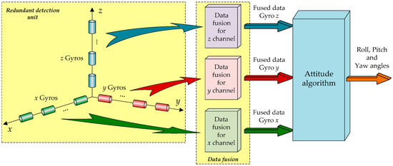
Figure 2.
General architecture of the redundant attitude system.
2.1. Theoretical Background of the Attitude Algorithm
A spacecraft flight attitude is represented by the Euler angles (roll, pitch, yaw), and, according to the strap-down INS theory, their estimation involves the use of data provided by a gyro triad. The literature provides many processing methods for the gyro data in order to estimate these angles, but most of them use one of the two well-known parameterizations, the quaternionic parameterization and the matrix parameterization. Actually, the target in both parameterizations is the attitude matrix associated with the relative rotation of the satellite and navigation frames, but the following numerical ways are different, being chosen by the navigator designer as a function of the navigation problem particularities. The numerical methods developed for both parameterizations aim at an accurate numerical integration of the differential Poisson attitude equations but also aim at the performing of a quick and precise ortho-normalization process in order to remove the errors due to the numerical truncations. In this regard, the ortho-normalization process in quaternionic parameterization shows several advantages involving just four parameters and a single constraint relationship, while the matrix parameterization involves the rotation matrix elements, i.e., nine parameters constrained by six relationships, three conditions for orthogonality and three for normality. Moreover, ortho-normalization procedure of the rotation (attitude) matrix requires the application of an iterative algorithm, proven to be an important time consumer [2,3,75,80,81,82].
For the here-presented attitude system, we chose the quaternionic parameterization. The Poisson quaternionic attitude equation, describing the dynamics of the angular relative position of the body frame (denoted with b) versus the navigation frame (denoted with n) (north–east–down (NED)—local horizontal frame), resulted in the form [2,3,75,80,81,82,83,84]:
(i = 0 ÷ 3)—the components of the attitude quaternion , —the derivative of the quaternion , —the angular speed components measured by the gyro triad. By choosing a Wilcox numerical integration method [75,82,83,84], the current values for the components of the quaternion (at time) are obtained from their previous values (at time) as follows:
where the coefficients and are given with the expressions in Table 1 [75,82,83,84] characterizing the m-order Wilcox algorithm; are the angular increments around the attitude axes (roll, pitch, yaw), is the norm associated with the total angular increment over a step time (). Under the assumption that is valid the commutation equation [75]:
i.e., are considered to be constant during a step time (), the angular increments around the attitude axes result in [75,82,83,84]:
denoted the matrix:

Table 1.
Coefficients of the numerical integration algorithm for various orders m.
The values of and coefficients depend on the algorithm order m but also by the norm [75,82,83,84],
Developing Equation (2), the current parameters of the attitude quaternion result by using the relations:
The numerical truncation during the integration step leads to a non-ortho-normal attitude quaternion, which generates wrong data conversion between the reference frames. A simplest numerical algorithm for the quaternion ortho-normalization recalculates its current parameters with the next equations [2,3,75,80,81,82,83,84]:
where the norm of the current attitude quaternion results from:
and are the components of the attitude quaternion after the ortho-normalization procedure.
Considering the equivalence of the attitude quaternion with the NED (north–east–down frame) to the body rotation matrix [2,3,75,80,81,82,83,84], the current values of the matrix elements are calculated with:
Correlating the numerical values provided by Equation (10) with the analytical formulas expressing the elements of the matrix according to the yaw (, pitch ( and roll () angles [2,3,75,80,81,82,83,84]:
the values of these attitude angles are easily obtained by using some inverse trigonometric functions, as follows [2,3,75,80,81,82,83,84]:
The numerical evaluations in Equation (12) consider the attitude angles trigonometric quadrants based the matrix elements calculated at past times and .
Having in mind that a numerical integration is performed to find the satellite attitude solution, an initialization phase is needed, providing to the algorithm the values of the attitude angles at time (( )). On the other hand, starting from these values, an initialization of the attitude quaternion is performed by using the next equations [83]:
2.2. Attitude Algorithm Software Implementation and Experimental Testing
The software implementation of the algorithm (Figure 3a) was made by using the Matlab/Simulink software package, which allowed us to test it through numerical simulation, but also by using experimentally acquired data. To develop the software associated with the mathematics of the previously exposed algorithm, an S-function was programmed, simultaneously implementing the ortho-normalization procedure but also the mechanism applied for the algorithm initialization.
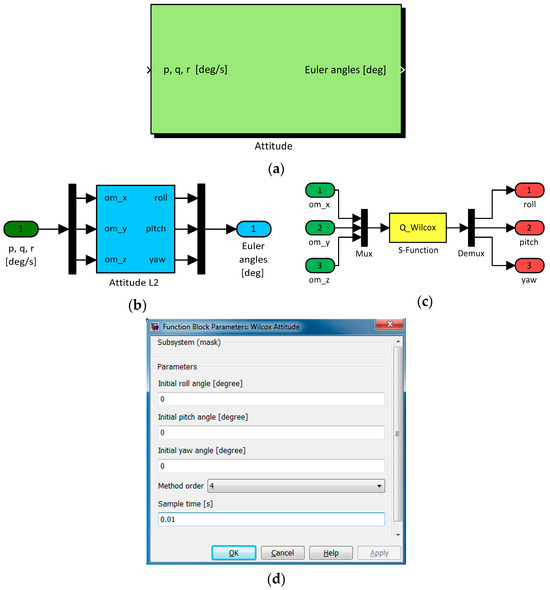
Figure 3.
Software implementation of the attitude algorithm: (a) Simulink block “Attitude”; (b) “Attitude L2” block; (c) layer accessing algorithm S-function; (d) graphical user interface (GUI).
A graphical user interface (GUI) (Figure 3d) masks the Simulink block “Attitude” in Figure 3a, which implements the attitude algorithm. The dynamic fields in the GUI facilitate the human user to initialize the algorithm by setting the initial values of the attitude angles and the integration step under the form of the sample time. At the same time, the selection of the method order is possible by using the interface, which means the changing of the and coefficients evaluation formulas (m = 1 to 6). The block in Figure 3a, called “Attitude”, is the first layer block in the software implementation, and it has as inputs the gyro readings ( ) expressed in degrees/s in this implementation. The block outputs are the attitude angles and are provided in degrees. In the implementation, the angular speeds were labeled with “p, q, r”, while the attitude angles were labeled with “Euler angles”. The second layer block (Figure 3b) in the backside of “Attitude” includes the block called “Attitude L2”, which implements in an S-function (Figure 3c) the algorithm for attitude determination.
In the evaluation phase, the software model was firstly numerical simulated, and subsequently experimentally tested on a bench in the lab and by using some experimentally acquired data [83]. The experimental model used for the testing at the lab level contained a strap-down inertial platform equipped with a gyro triad based on classical electro-mechanical gyro sensors, able to measure angular speeds of a maximum of 15°/s. The calibration of the gyro sensors has been performed by using a rotating platform, accurately controlled in angular speed. The numerical simulation analysis and the bench test results proved that the software model developed for the attitude algorithm works well, validating its operation in this way. The next tests were based on experimental data provided by a gyro triad with MEMS sensors, equipping the inertial measurement unit of the SDINS/GPS navigator. As a reference for the developed attitude algorithm evaluation, we used the attitude component (roll, pitch and yaw angles) of the solution of navigation offered by the SDINS/GPS integrated navigator. An example of such testing results is shown in Figure 4, where Figure 4a presents the measurements provided by the gyro triad ( ) and Figure 4b presents the graphical characteristics of the attitude angles provided by the algorithm and by the reference navigator. For the exposed example, the numerical integration method was used with the truncation order m = 6. The characteristics in Figure 4b show that the attitude solutions provided by the reference navigator and by the developed algorithm are very close. The biases of the MEMS gyros were estimated and corrected by using an offline method, involving the determination of the mean values of the gyro signals in static tests, while the SDINS/GPS reference navigator data processing algorithm, based on a Kalman filter, estimated and corrected the sensors biases in real time [83].
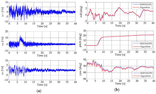
Figure 4.
Attitude algorithm evaluation with experimentally acquired data: (a) the angular speeds ( ) provided by the gyro sensors; (b) graphical characteristics of the attitude angles provided by the algorithm and by the reference navigator.
3. Data Fusion Algorithm
3.1. Mathematics of the Data Fusion Algorithm
Starting from the idea that it would be less expensive and safer to replace the classical arrangement of the IMU sensors (rectangular triads of gyros and accelerometers) with multiple miniaturized gyro and accelerometric sensors mounted on each of the three axes of the IMU (in linear detection clusters) to measure the same quantity and subsequently fuse their data, we conceived a data fusion method to combine the outputs of these multiple sensors to estimate better values for the components of the variables needed to calculate the satellite attitude, position and speed by using inertial methods.
The developed algorithm uses a mechanism based on the maximal ratio combining the data fusion method involved in the processing of the signals in the telecommunications field [79,85,86]. According to this data fusion mechanism, each sensor in a linear detection cluster is assigned a weight which is inversely proportional to the standard deviation calculated for a data package consisting of the last m samples that it supplies to the measurement system. The mechanism generates a parallel data fusion architecture for the algorithm in this way, as is presented in Figure 5 [79,84,87,88].
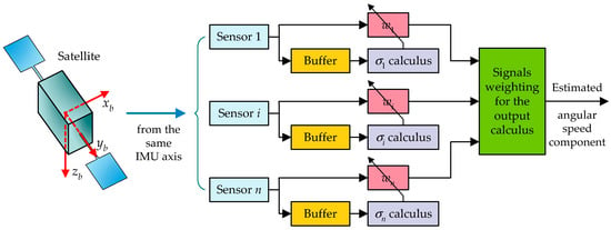
Figure 5.
Architecture of the data fusion algorithm.
Considering n sensors in the detection cluster of the same IMU axis, the evaluation of the standard deviation of the signal for the i-th sensor in the cluster, for a data frame of m consecutive samples, is realized by using the formula:
where denotes the j-th sample in the data frame measured by the i-th sensor and is the mean of the data frame,
Keeping in mind that the data fusion mechanism produces a weighted mean of the n sensors signals, the value of the sample (m + 1) in the fused signal is evaluated considering the quality of the n gyros signals for the previous m consecutive samples acquired from each of them. Therefore, the analysis of these n data frames (m consecutive samples for each sensor), obtained from the sensors in the cluster, provides n weights which are considered in the evaluation of the data fusion algorithm output for the next (m + 1) sample. The sensor weights for the (m + 1) sample are attributed in order to respect an inverse proportionality rule in relation to the standard deviation of its signal for a data package made up of the last m samples; a smaller standard deviation provides a larger weight to the sensor. If denotes the sample (m + 1) obtained from the i-th sensor, then the output of the data fusion algorithm at this (m + 1) sample is given by:
Applying the relations of inverse proportionality between weights and standard deviations, and bearing in mind that the sum of the weights equaling the unity [79,84,88],
it results in
Therefore, the data fusion algorithm output for the sample (m + 1) is obtained with:
A novelty element characterizing the data fusion algorithm may be regarded as its adaptive character due to the permanent change in the sensor weights in the calculus of the best values for the variable exciting the sensors depending on the statistical properties of the independent sensors measurements, given by their standard deviations.
3.2. Software Modelling and Experimental Testing of the Data Fusion Algorithm
As in the attitude algorithm situation, the software implementation involved the use of Matlab/Simulink facilities. Depending on the number of sensors considered in the detection cluster to be fused, various Simulink models allowed the testing and evaluation of the proposed algorithm performance through numerical simulation and experimental testing [88]. Taking into account the goal of the present research and the hardware possibilities to test experimentally such a redundant spacecraft attitude system, the team decided to use three detection clusters on the IMU axes, with four miniaturized gyros in linear configuration for each cluster. Therefore, in this section, we will give results obtained with the software model of the data fusion algorithm developed for detection clusters with four sensors.
The Matbal/Simulink model associated to the mathematics of the algorithm particularized for n = 4 sensors resulted as in Figure 6, and was called “Sensor data fusion” [79,84,88]. As the input, it has the data provided by the four sensors considered in the cluster (“Sensor 1”÷“Sensor 4”), and as the output, it has the fused signal (“fused signal”), the standard deviation of the fused signal (“fused signal std”), the standard deviations of the four sensors data (“std1”÷“std4”), and the weights (“w1”÷“w4”) assigned to each of the sensors in cluster. Looking under the mask of the “Sensor data fusion” block, we can see that the input data obtained from the sensors are multiplexed and then passed through a “Buffer” block, which generates data frames of m successive samples for each of the four sensors channels considered as inputs; actually, the data stored at a moment of time are distributed in a matrix n × m. In the “Buffer” settings, we opted for a structure with m = 100 samples (n × m = 4 × 100) in a FIFO (first in first out) configuration, which means that in each channel between two consecutive data frames, there will be 99 common samples. From this perspective, the implementation follows the mathematical flow, with the evaluation of the standard deviations (by using the “Standard deviation” block) for each data frame provided by the “Buffer”, with the determination of the sensor’s associated weights for each data frame of 100 samples, and with the calculation of the data fusion result for each set of four input samples provided by the four sensors in the cluster (Equations (18) and (19)). As a measure to detect and isolate defects, the user imposes a threshold above which the standard deviation is considered abnormal for the functioning of the type of sensor used in the cluster, and when this threshold is exceeded, the sensor receives a null weight and is excluded from the calculus which estimates the fused signal. The sensor receives also a null weight if it provides data for which the calculated standard deviation is zero. This protection mechanism is implemented in the simulation model by using the “Switch” block. Therefore, the “Switch” block is the one that decides the correct operation of each of the four sensors, having the ability to give zero weight, in the calculation of the output value, to those that have failed. The blocks between “Switch” and “Product” compete to implement Equation (18) for each of the four measurement channels. The completion of the implementation of Equation (19) is achieved with the “Product” block, to whose input the information read on the four channels at the sample m+1 is brought, and with the “Matrix Sum1” and “Frame Status Conversion” blocks, which perform the summation of the weighted inputs, respectively, and the conversion of the numeric format of the output .
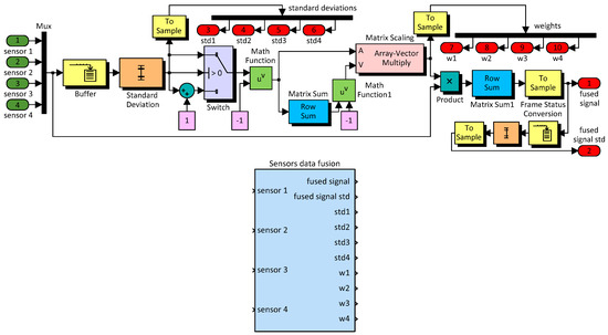
Figure 6.
Data fusion algorithm Matlab/Simulink model for n = 4.
As was already mentioned, the software model implementing the data fusion algorithm was simulated and evaluated in various situations. Since the data fusion algorithm must be valid regardless of the physical quantity measured by the sensors used in the clusters, one of the most practical options we had for testing at the laboratory level was the use of four accelerometers in the cluster measurement. This type of test was adopted considering the fact that accelerometers do not differentiate between gravitational and kinematic acceleration and static tests could be carried out based on the excitation of the sensors by the local gravitational acceleration, with the sensitivity axis of the cluster oriented in three directions very well controlled. Therefore, this easiest testing procedure was applied on the bench in the laboratory by using the signals from an accelerometric cluster with four sensors. The procedure was the simplest because it necessitated only an adjustable table with an air bubble to align horizontally the inertial detection unit, naturally excited by the local gravitational field in three situations, , and , where the sensitivity axis of the cluster was directed horizontally, and along the local vertical, up and down. An NI-DAQ USB 6210 data acquisition card was used to acquire the data from each sensor in the cluster, with a sampling rate of 100 samples/s per channel. Figure 7 shows the sensor outputs and the results of data fusion obtained during the tests, while Table 2 provides the mean values of the standard deviations for data measured by the sensors and for fused signal for all of the three tested situations (“r1” ÷ “r4” are the measurements provided by the each of the four sensors in the cluster, while “f” is the fused signal).
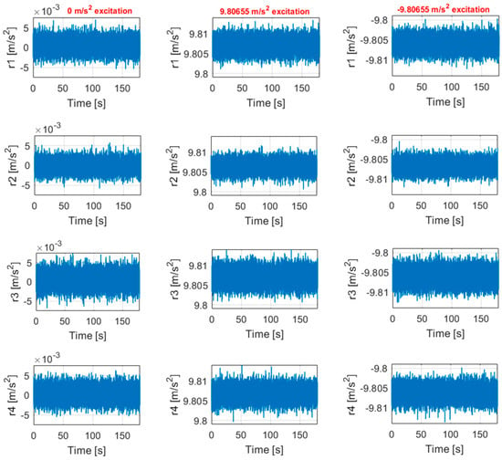

Figure 7.
The sensors outputs and the results of the data fusion obtained during the tests (n = 4).

Table 2.
The mean values of the standard deviations for sensor data and for fused signal.
Given the characteristics in Figure 7 and the values in Table 2, the second sensor may be categorized to be the best in the linear cluster, while the third sensor may be considered the worst. Figure 7 shows a decrease in the noise amplitude for the fused signal in comparison with the sensor signals. The same thing is revealed by the mean values for the standard deviation in Table 2. On the other hand, these values indicate that the standard deviation of the fused signal decreased by 1.7720 times comparatively with sensor no. 2 (the best in cluster), by 2.2661 times comparatively with sensor no. 3 (the worst in cluster), and by 2.0266 times comparatively with the average of the mean dispersions for all sensors in the cluster, when its sensitivity axis was on the horizontal plane. In the other two testing cases, the obtained reductions for the mean standard deviation were as follows: (1) at 9.80655 m/s2 excitation: 1.7694 times comparatively with sensor no. 2, 2.2565 times comparatively with sensor no. 3, and 2.0256 times comparatively with the average of the mean dispersions; (2) at −9.80655 m/s2 excitation: 1.7564 comparatively with sensor no. 2, 2.3803 times comparatively with sensor no. 3, and 2.0140 times comparatively with the average of the mean dispersions. All tested situations, as well as the numerical simulations, show that the data fusion algorithm produced a reduction in the signal noise power approximately proportional to the number of sensors equipping the cluster. Moreover, for the situations when the sensor biases were not compensated, it was noted that a fused signal with a reduced bias was obtained due to this statistical combination of the sensor signals.
4. Results Obtained during the Testing of the Redundant Attitude System with Experimental Data
Once verified all algorithms and software components were included in the proposed inertial redundant attitude system, a global validation software model was conceived in Matlab/Simulink (Figure 8). It puts together the data fusion mechanism for all three redundant clusters of gyros, used on the x, y and z axes of the IMU, with the attitude calculation mechanism starting from the fused data provided by each cluster. In the same model, the attitude calculation mechanism takes data from four groups by three gyros disposed on the IMU axes (in each group is one gyro from each redundant cluster), which generates inputs that are then fused.
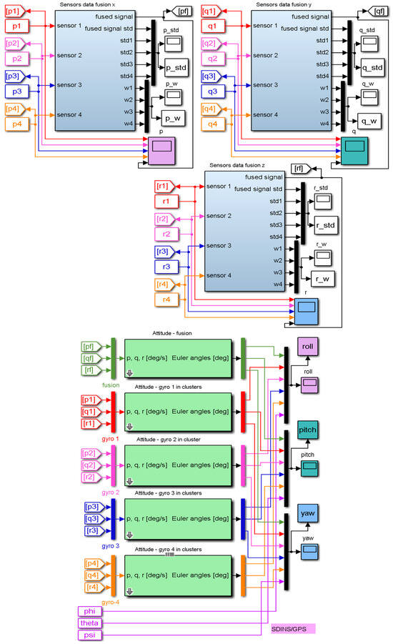
Figure 8.
Software model for redundant attitude system evaluation with experimental data.
The testing of the integrated system was performed based on a few sets of experimentally acquired inertial data. In this way, a 3D redundant gyro detection unit was manufactured and used together with an SDINS/GPS integrated navigation system on a testing car to record the needed data (Figure 9). The SDINS/GPS provided the reference solution for attitude angles, keeping in mind that it generates this solution by combining Kalman filter data for both GPS and SDINS navigators. Our 3D redundant gyro detection unit included twelve MEMS gyros, which were disposed in three clusters with four sensors in each of them, allowing the measurement of angular speeds.
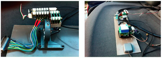
Figure 9.
Detection unit experimental platform used in the recording of the evaluation data.
The model in Figure 8 includes three “Sensors data fusion” blocks, one for each detection channel, and five “Attitude” blocks supplied with signals from the “Sensors data fusion” blocks outputs (“Attitude—fusion” block supplied with pf, qf and rf fused signals, which are the fused values obtained for the angular speed components in body frame ), and from the four gyro triads formed with the i-th sensor in each detection cluster, i = 1 to 4 (“Attitude—gyro 1 in clusters”—supplied with the measured components of the angular speed in body frame , “Attitude—gyro 2 in clusters”—supplied with the measured components of the angular speed in the body frame , “Attitude—gyro 3 in clusters”—supplied with the measured components of the angular speed in the body frame , and “Attitude—gyro 4 in clusters”—supplied with the measured components of the angular speed in the body frame ).
Thus, the model allows the evaluation of the attitude starting from the fused signals and from the four gyro triads with perturbed angular speed signals. In the model is also added the reference attitude angles provided by the SDINS/GPS integrated navigator (phi—roll, theta—pitch, psi—yaw). In addition to the six sets of attitude angles included in the output vectors “roll”, “pitch” and “yaw”, the model in Figure 8 allows the evaluation of the standard deviations for all sensors implied in the detection mechanism, but also for the fused signals obtained from the sensor clusters placed on all three axes of the IMU. For the x-axis of redundant IMU, the standard deviations of the sensors (“std1” ÷ “std4”) and of the fused signal (“fused signal std”) are stored in the output vector “p_std” of the “Sensors data fusion x” block; for the y-axis, the standard deviations of the sensors (“std1” ÷ “std4”) and of the fused signal (“fused signal std”) are stored in the output vector “q_std” of the “Sensors data fusion y” block, and for the z-axis, the standard deviations of the sensors (“std1” ÷ “std4”) and of the fused signal (“fused signal std”) are stored in the output vector “r_std” of the “Sensors data fusion z” block. Also, the model provides as outputs the weights (“w1” ÷ “w4”) assigned to each sensor in the clusters on the three axes of the IMU. For the x-axis, the weights are stored in the output vector “p_w” of the “Sensors data fusion x” block, for the y-axis are stored in the output vector “q_w” of the “Sensors data fusion y” block, and for the z-axis are stored in the output vector “r_w” of the “Sensors data fusion z” block.
A three-minute sequence from an experimentally acquired gyro data set and the fusion results obtained by applying its components on the inputs of the model in Figure 8 (p1 ÷ p4 for the x detection channel, representing the measurements for ; q1 ÷ q4 for the y detection channel, representing the measurements for , and r1 ÷ r4 for the z detection channel, representing the measurements for ) are presented in Figure 10.
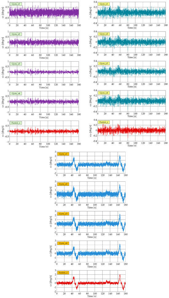
Figure 10.
A sequence from an experimentally acquired gyro data set and the fusion results.
The standard deviations of all this data (inputs and fused signals) are shown in Figure 11; in the upper part of the figure, the standard deviations afferent to gyro sensors data are shown, while the lower part depicts the resulting standard deviations for fused signals.
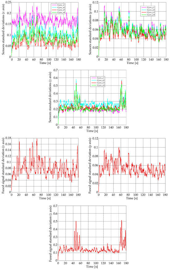
Figure 11.
Gyro sensors and fused signals standard deviations.
Figure 10 shows a reduced noise level in the fused signals comparatively with the experimentally measured data in all three detection channels, confirmed also by the numerical values related to the graphic characteristics of the standard deviations for fused signals presented in Figure 11.
Figure 8 the attitude solutions provided by the fused signals processing (“Attitude—fusion” block), by the reference SDINS/GPS integrated navigator and by the gyro triads formed with the first sensor in each detection cluster data processing (“Attitude—gyro 1 in clusters” block) the characteristics in Figure 12 were obtained. The initialization of the “Attitude” blocks was realized considering the first values of the attitude angles in the analyzed data sequence provided by the reference SDINS/GPS integrated navigator: initial roll angle = 0.027 degrees, initial pitch angle = 0.051 degrees, and initial pitch angle = 108.103 degrees.
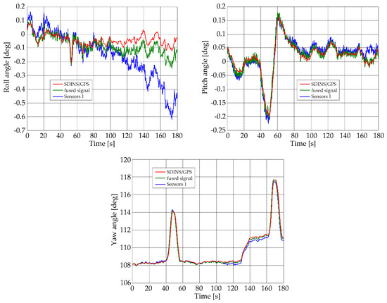
Figure 12.
Attitude solutions for reference navigator, fused signals (proposed redundant attitude system) and raw signals, obtained for 1st sensor in each detection cluster.
Figure 13 presents the graphic results obtained evaluating the roll, pitch and yaw angle deviations (attitude angle errors) between the attitude reference solution (SDINS/GPS navigator solution) and the attitude solutions provided by the proposed redundant attitude system, but also by the non-redundant architecture, which used the information provided by the first gyro in each redundant detection cluster on the IMU axes. The evaluation of the maximum absolute values of these deviations for the proposed system over the analyzed data sequence found a value of 0.1468 degrees for the roll angle, a value of 0.0487 degrees for the pitch angle, and 0.6558 degrees for the yaw angle. A similar analysis performed for the non-redundant configuration led to maximum absolute values of 0.5020 degrees for the deviation in the roll angle, 0.0674 degrees for the deviation in the pitch angle, and 1.1603 degrees for the deviation in the yaw angle. These maximum absolute values of the deviations, but also the characteristics in Figure 12 and Figure 13, proved an important increase in the level of accuracy of attitude angles calculation when the proposed redundant configuration is used compared to the situation where a non-redundant configuration is used.
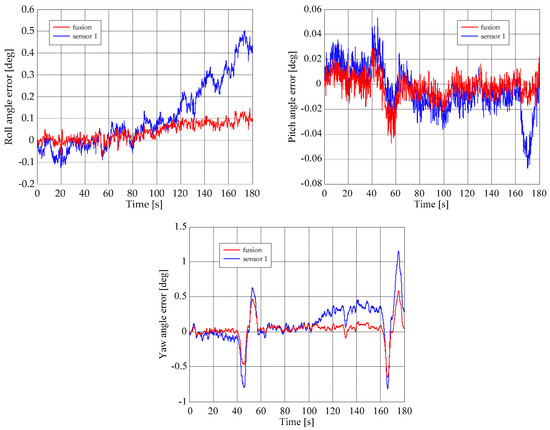
Figure 13.
Deviations of the attitude angles from the attitude reference solution.
5. Conclusions
The paper proposed a new redundant inertial attitude system, with a detection unit containing three gyro sensor clusters arranged in linear configurations. The direct application of the here proposed methodology is the estimation of small satellites’ attitude-based gyro measurements, providing at the same time a high degree of redundancy of the inertial detection unit equipped with miniaturized sensors. The concept started from the idea that it would be less expensive and safer to replace the classical arrangement of the IMU sensors (rectangular triads of gyros) with multiple miniaturized gyros mounted on each of the three axes of the IMU (in linear detection clusters) to measure the same quantity and subsequently fuse their data. The developed data fusion method combined the outputs of these multiple sensors to estimate improved values for the components of the variables needed to calculate the satellite attitude in terms of roll, pitch, and yaw attitude angles by using inertial methods. The developed algorithm used a mechanism based on the maximal ratio combining the data fusion method involved in the processing of the signals in the telecommunications field.
The integrated architecture of the redundant attitude-system-based inertial techniques included the following: (1) a 3D redundant gyro detection unit with twelve MEMS gyros, which were disposed in three clusters with four sensors in linear configuration in each of them, allowing the measurement of angular speeds along the body frame axes; (2) three data fusion blocks, one for each detection channel, implementing software the data fusion method; and (3) the attitude algorithm, implementing software the numerical signal processing flow used in the determination of attitude angles starting from the gyro data.
First tested was the attitude algorithm; its numerical simulation analysis and the bench test results proved that the software model developed for the algorithm worked well, validating in this way its operation. The next tests for the attitude algorithm were based on experimental data provided by a gyro triad with MEMS sensors, equipping the inertial measurement unit of the SDINS/GPS navigator. As a reference for the developed attitude algorithm evaluation, we used the attitude component (roll, pitch and yaw angles) of the solution of navigation offered by the SDINS/GPS integrated navigator. The obtained results showed that the attitude solutions provided by the reference navigator and by the developed algorithm were very close.
The next on the test list was the software model implementing the data fusion algorithm, which was also simulated and evaluated in various situations. A simple experimental test performed at the laboratory level was the use of four accelerometers in the cluster measurement, naturally excited by the local gravitational field in three situations, , and , where the sensitivity axis of the cluster was directed horizontally, and along the local vertical, up and down. The obtained results show that the standard deviation of the fused signal decreased by 1.7720 times comparatively with sensor no. 2 (the best in the cluster), by 2.2661 times comparatively with sensor no. 3 (the worst in the cluster), and by 2.0266 times comparatively with the average of the mean dispersions for all sensors in the cluster, when its sensitivity axis was on the horizontal plane. In the other two testing cases, the obtained reductions for the mean standard deviation were as follows: (1) at 9.80655 m/s2 excitation: 1.7694 times comparatively with sensor no. 2, 2.2565 times comparatively with sensor no. 3, and 2.0256 times comparatively with the average of the mean dispersions; (2) at −9.80655 m/s2 excitation: 1.7564 comparatively with sensor no. 2, 2.3803 times comparatively with sensor no. 3, and 2.0140 times comparatively with the average of the mean dispersions. All tested situations, as well as the numerical simulations, showed that the data fusion algorithm produced a reduction in the signal noise power approximately proportional to the number of sensors equipping the cluster. Moreover, for the situations when the sensor biases were not compensated, a fused signal was obtained with a reduced bias due to this statistical combination of the sensor signals.
The final tests were reserved for the integrated redundant inertial attitude system. Its testing was performed based on a few sets of experimentally acquired inertial data. In this way, a 3D redundant gyro detection unit was manufactured and used together with an SDINS/GPS integrated navigation system on a testing car to record the needed data. The SDINS/GPS provided the reference solution for attitude angles, keeping in mind that it generates this solution by combining Kalman filter data for both GPS and SDINS navigators. The developed 3D redundant gyro detection unit included twelve MEMS gyros, which were disposed in three clusters with four sensors in each of them, allowing the measurement of angular speeds. For a test sequence of 3 min, the evaluation of the maximum absolute values of the roll, pitch and yaw angle deviations between the attitude reference solution (SDINS/GPS navigator solution) and the attitude solution provided by the proposed redundant attitude system found a value of 0.1468 degrees for the roll angle, a value of 0.0487 degrees for the pitch angle, and 0.6558 degrees for the yaw angle. A similar analysis performed for the non-redundant configuration, which used the information provided by the first gyro in each redundant detection cluster on the IMU axes, led to maximum absolute values of 0.5020 degrees for the deviation in the roll angle, 0.0674 degrees for the deviation in the pitch angle, and 1.1603 degrees for the deviation in the yaw angle, showing a low accuracy compared with the redundant configuration.
Therefore, the analysis of each component of the proposed redundant attitude system shows promising benefits for their use in future satellite attitude systems or in the estimation of better values for different variables, measured by using sensor networks in redundant linear configurations. More important were the benefits shown by the redundant attitude system as a whole, which proved an important increase in the level of accuracy of attitude angles calculation when the proposed redundant configuration is used, compared to the situation where a non-redundant configuration is used, but also offer a high degree of redundancy in the evaluation of the three-axis attitude solution for small satellites, in terms of roll, pitch, and yaw angles, by using strap-down inertial techniques.
Author Contributions
T.L.G. proposed, conceived, modeled and tested the data fusion method variant for inertial navigators, and developed, modeled and simulated the attitude algorithm. T.L.G. and M.Ș.M. integrated software the redundant attitude system and analyzed its behavior with experimentally acquired data. T.L.G. and M.Ș.M. performed the bench testing of the attitude algorithm. T.L.G. recorded the experimental data needed for the analysis of each component of the proposed redundant attitude system, but also for analysis of the redundant attitude system as a whole. M.Ș.M. wrote the original draft and T.L.G. revised and edited the final form. All authors have read and agreed to the published version of the manuscript.
Funding
This work was supported by CNCSIS-UEFISCDI, project PN II-RU, No. 1/28.07.2010, “High-precision strap-down inertial navigators, based on the connection and adaptive integration of the nano and micro inertial sensors in low cost networks, with a high degree of redundance”, code TE_102/2010.
Institutional Review Board Statement
Not applicable.
Informed Consent Statement
Not applicable.
Data Availability Statement
The datasets presented in this article are not readily available because the work was supported by UEFISCDI—Executive Agency for Higher Education, Research, Development and Innovation Funding in Romania, project PN II-RU, No. 1/28.07.2010. Requests to access the datasets should be directed to UEFISCDI in Romania.
Conflicts of Interest
The authors declare no conflicts of interest.
References
- Quinchia, A.G.; Falco, G.; Falletti, E.; Dovis, F.; Ferrer, C. A comparison between different error modeling of MEMS applied to GPS/INS integrated systems. Sensors 2013, 13, 9549–9588. [Google Scholar] [CrossRef]
- Titterton, D.H.; Weston, J. Strapdown Inertial Navigation Technology, 2nd ed.; Institution of Engineering and Technology: Stevenage, UK, 2004. [Google Scholar]
- Farrell, J. Aided Navigation. GPS with High Rate Sensors; McGraw-Hill: New York, NY, USA, 2008. [Google Scholar]
- Gill, E.; Simone D’Amico, S.; Montenbruck, O. Autonomous Formation Flying for the PRISMA Mission. J. Spacecr. Rocket. 2007, 44, 671–681. [Google Scholar] [CrossRef]
- Capuano, V.; Botteron, C.; Wang, Y.; Tian, J.; Leclère, J.; Farine, P.A. GNSS/INS/Star Tracker Integrated Navigation System for Earth-Moon Transfer Orbit. In Proceedings of the 27th International Technical Meeting of the Satellite Division of The Institute of Navigation (ION GNSS + 2014), Tampa, FL, USA, 8–12 September 2014; pp. 1433–1447. [Google Scholar]
- Sazdovski, V.; Kitanov, A.; Petrovic, I. Implicit observation model for vision aided inertial navigation of aerial vehicles using single camera vector observations. Aerosp. Sci. Technol. 2015, 40, 33–46. [Google Scholar] [CrossRef]
- Li, X.; Li, C. Navigation and Guidance of Orbital Transfer Vehicle; Springer Nature Singapore Pte Ltd.: Singapore; National Defense Industry Press: Beijing, China, 2018. [Google Scholar]
- Erkec, T.Y.; Hajiyev, C. Review on Relative Navigation Methods of Space Vehicles. Curr. Chin. Sci. 2021, 1, 184–195. [Google Scholar] [CrossRef]
- Erkec, T.Y.; Hajiyev, C. The methods of relative navigation of satellites formation flight. Int. J. Sustain. Aviat. 2021, 6, 260–279. [Google Scholar] [CrossRef]
- Scharnagl, J. Distributed Guidance, Navigation and Control for Satellite Formation Flying Missions. Ph.D. Thesis, Universität Würzburg—Schweinfurt, Würzburg, Germany, 2022. [Google Scholar]
- iXblue. Available online: https://www.ixblue.com/photonics-space/inertial-navigation-for-space/ (accessed on 4 July 2024).
- Safran. Available online: https://safran-navigation-timing.com/product/spacenaute/ (accessed on 4 July 2024).
- Advanced Navigation. Available online: https://www.advancednavigation.com/space (accessed on 4 July 2024).
- Australian Space Agency. Available online: https://www.space.gov.au/news-and-media/navigating-distant-frontiers-ai-and-quantum-technology (accessed on 4 July 2024).
- Advanced Navigation—News. Available online: https://www.advancednavigation.com/news/advanced-navigation-helps-nasa-get-mars/ (accessed on 4 July 2024).
- Q-CTRL. Available online: https://q-ctrl.com/case-study/developing-a-quantum-assured-navigation-solution (accessed on 4 July 2024).
- Somov, Y.; Butyrin, S.; Somov, S. Inertial Navigation and Control of a Space Robot for Servicing a Geostationary Satellite. In Proceedings of the 28th Saint Petersburg International Conference on Integrated Navigation Systems (ICINS), Saint Petersburg, Russia, 31 May–2 June 2021; pp. 1–5. [Google Scholar]
- He, Z.; Fei, B.; Du, J. Inertial Navigation Method for Spacecraft Based on General Relativity. In Innovative Computing. Lecture Notes in Electrical Engineering; Hung, J.C., Chang, J.W., Pei, Y., Wu, W.C., Eds.; Springer: Singapore, 2022; Volume 791, pp. 79–86. [Google Scholar]
- Mannings, R. Ubiquitous Positioning; Artech House: London, UK, 2008. [Google Scholar]
- He, L.; Ma, W.; Guo, P.; Sheng, T. Developments of attitude determination and control system of microsats: A survey. Proc. Inst. Mech. Eng. Part I J. Syst. Control. Eng. 2021, 235, 1733–1750. [Google Scholar] [CrossRef]
- Reichel, F.; Bangert, P.; Busch, S.; Ravandoor, K.; Schilling, K. The Attitude Determination and Control System of the Picosatellite UWE-3*. In Proceedings of the 19th IFAC Symposium on Automatic Control in Aerospace, Würzburg, Germany, 2–6 September 2013; pp. 271–276. [Google Scholar]
- Ni, S.; Zhang, C. Attitude determination of nano satellite based on gyroscope, Sun sensor and magnetometer. Procedia Eng. 2011, 15, 959–963. [Google Scholar] [CrossRef][Green Version]
- Kumar, J.S.J.; Gunasekar, S.; Shekhar, H.; Gupta, S.D. Design of MEMS Based Attitude Determination and Control System for Nanosatellite. Int. J. Recent Trends Eng. 2009, 1, 316–319. [Google Scholar]
- Mok, S.H.; Byeon, S.Y.; Bang, H.; Choi, Y. Performance comparison of gyro-based and gyroless attitude estimation for cubesats. Int. J. Control. Autom. Syst. 2020, 18, 1150–1160. [Google Scholar] [CrossRef]
- Colagrossi, A.; Lavagna, M.; Bertacin, R. An Effective Sensor Architecture for Full-Attitude Determination in the HERMES Nano-Satellites. Sensors 2023, 23, 2393. [Google Scholar] [CrossRef]
- Mimasu, Y.; van der Ha, J.C.; Narumi, T. Attitude Determination by Magnetometer and Gyros during Eclipse. In Proceedings of the AIAA/AAS Astrodynamics Specialist Conference and Exhibit, Honolulu, HI, USA, 18–21 August 2008; pp. 1–14. [Google Scholar]
- Stearns, H.; Tomizuka, M. Multiple Model Adaptive Estimation of Satellite Attitude using MEMS Gyros. In Proceedings of the American Control Conference, San Francisco, CA, USA, 29 June–1 July 2011; pp. 3490–3495. [Google Scholar]
- Tissera, M.S.C.; Low, K.S.; Goh, S.T. On-orbit Gyroscope Bias Compensation to Improve Satellite Attitude Control Performance. In Proceedings of the IEEE Aerospace Conference (50100), Big Sky, MT, USA, 6–13 March 2021; pp. 1–10. [Google Scholar]
- Pérez, L.L.; Koch, P.; Smith, D.; Walker, R. GOMX-4, the most advance nanosatellite mission for IOD purposes. In Proceedings of the 4S Symposium, 125, Sorrento, Italy, 28 May–1 June 2018; pp. 12–30. [Google Scholar]
- Liu, Z.; Zhou, K.; Sun, X. Satellite Attitude Determination Using ADS-B Receiver and MEMS Gyro. Aerospace 2023, 10, 370. [Google Scholar] [CrossRef]
- Hauschild, A.; Montenbruck, O. GPS-based attitude determination for microsatellites. In Proceedings of the ION GPS 2007, Fort Worth, TX, USA, 25–28 September 2007; pp. 2424–2434. [Google Scholar]
- Scaccia, M. Numerical Algorithms for Attitude Determination Using GPS. Master’s Thesis, School of Computer Science, McGill University, Montreal, QC, Canada, 2011. [Google Scholar]
- Rakisheva, Z.; Sukhenko, A.; Kaliyeva, N. Optimization Issues in the Problem of Small Satellite Attitude Determination and Control. In Modeling and Optimization in Space Engineering. State of the Art and New Challenges; Fasano, G., Pintér, D.J., Eds.; Springer Optimization and Its Applications Bookseries; Springer: Cham, Switzerland, 2019; Volume 144, pp. 373–393. [Google Scholar]
- Kuwahara, T. Introduction to CubeSat Attitude Control System. Tohoku University. Department of Aerospace Engineering. KiboCUBE Academy. Available online: https://www.unoosa.org/documents/pdf/psa/access2space4all/KiboCUBE/AcademySeason2/On-demand_Pre-recorded_Lectures/KiboCUBE_Academy_2021_OPL14.pdf (accessed on 12 July 2024).
- Masi, S. Attitude Determination and Attitude Control. Sapienza Universita di Roma—Dipartimento di Fisica, Methods of Space Astrophysics. Available online: https://oberon.roma1.infn.it/metodiastrofisicaspaziale/lezione_7_2015.pdf (accessed on 12 July 2024).
- Enger, E. Spacecraft Attitude Determination Methods in an Educational Context; KTH Royal Institute of Technology, School of Engineering Sciences: Stockholm, Sweden, 2019. [Google Scholar]
- Markley, F.L.; Crassidis, J.L. Fundamentals of Spacecraft Attitude Determination and Control; Spinger: New York, NY, USA, 2014. [Google Scholar]
- Crassidis, J.L.; Markley, F.L.; Cheng, Y. Survey of nonlinear attitude estimation methods. J. Guid. Control. Dyn. 2007, 30, 12–28. [Google Scholar] [CrossRef]
- Ismail, Z.; Varatharajoo, R.; Chak, Y.C. A fractional-order sliding mode control for nominal and underactuated satellite attitude controls. Adv. Space Res. 2020, 66, 321–334. [Google Scholar] [CrossRef]
- Sofyalı, A.; Jafarov, E.M. Integral Sliding Mode Control of Small Satellite Attitude Motion by Purely Magnetic Actuation. In Proceedings of the 19th World Congress The International Federation of Automatic Control, Cape Town, South Africa, 24–29 August 2014; pp. 7947–7953. [Google Scholar]
- Cao, L.; Li, X.; Chen, X.; Zhao, Y. Minimum sliding mode error feedback control for fault tolerant small satellite attitude control. Adv. Space Res. 2014, 53, 309–324. [Google Scholar] [CrossRef]
- Navabi, M.; Hashkavaei, N.S.; Reyhanoglu, M. Satellite attitude control using optimal adaptive and fuzzy controllers. Acta Astronaut. 2023, 204, 434–442. [Google Scholar] [CrossRef]
- Meng, Z.; Liang, H. Adaptive attitude maneuver control for satellite with large scale antenna in space thermal environment. Adv. Space Res. 2022, 70, 2227–2239. [Google Scholar] [CrossRef]
- Sadigh, S.M.; Kashaninia, A.; Dehghan, S.M.M. Adaptive finite-time fault-tolerant control for nano-satellite attitude tracking under actuator constraints. Aerosp. Sci. Technol. 2023, 138, 108337. [Google Scholar] [CrossRef]
- Fan, L.; Huang, H.; Sun, L.; Zhou, K. Robust attitude control for a rigid-flexible-rigid microsatellite with multiple uncertainties and input saturations. Aerosp. Sci. Technol. 2019, 95, 105443. [Google Scholar] [CrossRef]
- Li, Y.; Ye, D.; Sun, Z. Robust finite time control algorithm for satellite attitude control. Aerosp. Sci. Technol. 2017, 68, 46–57. [Google Scholar] [CrossRef]
- Han, C.; Guo, J.; Pechev, A. Nonlinear H∞ based underactuated attitude control for small satellites with two reaction wheels. Acta Astronaut. 2014, 104, 159–172. [Google Scholar] [CrossRef]
- Zhang, B.; Liu, K.; Xiang, J. A stabilized optimal nonlinear feedback control for satellite attitude tracking. Aerosp. Sci. Technol. 2013, 27, 17–24. [Google Scholar] [CrossRef]
- MacKunis, W.; Leve, F.; Patre, P.M.; Fitz-Coy, N.; Dixon, W.E. Adaptive neural network-based satellite attitude control in the presence of CMG uncertainty. Aerosp. Sci. Technol. 2016, 54, 218–228. [Google Scholar] [CrossRef]
- Shehzad, M.F.; Asghar, A.B.; Jaffery, M.H.; Naveed, K.; Čonka, Z. Neuro-fuzzy system based proportional derivative gain optimized attitude control of CubeSat under LEO perturbations. Heliyon 2023, 9, e20434. [Google Scholar] [CrossRef]
- Bello, A.; del Castañedo, A.; Olfe, K.S.; Rodríguez, J.; Lapuerta, V. Parameterized fuzzy-logic controllers for the attitude control of nanosatellites in low earth orbits. A comparative studio with PID controllers. Expert Syst. Appl. 2021, 174, 114679. [Google Scholar] [CrossRef]
- Barbour, N.M.; Schmidt, G. Inertial Sensor Technology Trends. IEEE Sens. J. 2001, 1, 332–339. [Google Scholar] [CrossRef]
- Barbour, N.; Hopkins, R.; Kourepenis, A.; Ward, P. Inertial MEMS Systems and Applications. In Proceedings of the RTO-EN-SET-116, Low-Cost Navigation Sensors and Integration Technology, Bagneux, France, 28–29 March 2011. [Google Scholar]
- KVH Industries, Inc. Guide to Comparing Gyro and IMU Technologies—Micro-Electro-Mechanical Systems and Fiber Optic Gyros; KVH Industries, Inc.: Middletown, RI, USA, 2014. [Google Scholar]
- Hasan, A.M.; Samsudin, K.; Ramli, A.R.; Azmir, R.S. Wavelet-based pre-filtering for low cost inertial sensors. J. Appl. Sci. 2010, 10, 2217–2230. [Google Scholar] [CrossRef][Green Version]
- Mao, B.; Wu, J.W.; Wu, J.T.; Zhou, X.M. MEMS Gyro Denoising Based on Second Generation Wavelet Transform. In Proceedings of the First International Conference on Pervasive Computing, Signal Processing and Applications, Harbin, China, 17–19 September 2010; pp. 255–258. [Google Scholar]
- Skaloud, B.; Bruton, A.M.; Schwartz, K. Detection and filtering of short-term (1/f) noise in inertial sensors. J. ION 1999, 46, 97–107. [Google Scholar] [CrossRef]
- Soták, M. Application of wavelet analysis to inertial measurements. Sci. Mil. 2008, 3, 17–20. [Google Scholar]
- Ramalingam, R.; Anitha, G.; Shanmugam, J. Microelectromechnical systems inertial measurement unit error modelling and error analysis for low-cost strapdown inertial navigation system. Def. Sci. J. 2009, 59, 650–658. [Google Scholar] [CrossRef]
- Lee, T.G.; Sung, C.K. Estimation technique of fixed sensor errors for SDINS calibration. Int. J. Control. Autom. Syst. 2004, 2, 536–541. [Google Scholar]
- Shen, S.C.; Chen, C.J.; Huang, H.J. A new calibration method for low cost MEMS inertial sensor module. J. Mar. Sci. Technol. 2010, 18, 819–824. [Google Scholar] [CrossRef]
- Aydemira, G.A.; Saranli, A. Characterization and calibration of MEMS inertial sensors for state and parameter estimation applications. Measurement 2012, 45, 1210–1225. [Google Scholar] [CrossRef]
- Wang, L.; Wang, F. Intelligent Calibration Method of low cost MEMS Inertial Measurement Unit for an FPGA-based Navigation System. Int. J. Intell. Eng. Syst. 2011, 4, 32–41. [Google Scholar] [CrossRef]
- Yuan, J.; Yuan, Y.; Liu, F.; Pang, Y.; Lin, J. An improved noise reduction algorithm based on wavelet transformation for MEMS gyroscope. Front. Optoelectron. 2015, 8, 413–418. [Google Scholar] [CrossRef]
- Oliveira, O.J.; Filho, W.C.L.; Milagre da Fonseca, I. Inertial measurement unit calibration procedure for a redundant tetrahedral gyro configuration with wavelet denoising. J. Aerosp. Technol. Manag. 2012, 4, 163–168. [Google Scholar] [CrossRef]
- Liu, Y.; Xu, X.; Liu, X.; Yao, Y.; Wu, L.; Sun, J. A Self-Alignment Algorithm for SINS Based on Gravitational Apparent Motion and Sensor Data Denoising. Sensors 2015, 15, 9827–9853. [Google Scholar] [CrossRef]
- Shi, Y.S.; Gao, Z.F. Study on MEMS Gyro Signal De-Noising Based on Improved Wavelet Threshold Method. Appl. Mech. Mater. 2013, 433–435, 1558–1562. [Google Scholar]
- Noureldin, A.; Armstrong, J.; El-Shafie, A.; Karamat, T.; McGaughey, D.; Korenberg, M.; Hussain, A. Accuracy enhancement of inertial sensors utilizing high resolution spectral analysis. Sensors 2012, 12, 11638–11660. [Google Scholar] [CrossRef]
- Grigorie, T.L.; Botez, R.M. A new method to reduce the noise of the miniaturised inertial sensors disposed in redundant linear configurations. Aeronaut. J. 2013, 117, 111–132. [Google Scholar] [CrossRef]
- Grigorie, T.L.; Obreja, R.; Sandu, D.G.; Corcau, J.I. Allan variance analysis of the miniaturized sensors in a strap-down inertial 869 measurement unit. In Proceedings of the 12th International Multidisciplinary Scientific GeoConference—SGEM2012, Albena, Bulgaria, 17–23 June 2012; Volume 3, pp. 443–450. [Google Scholar]
- Kim, H.; Lee, J.G.; Park, C.G. Performance improvement of GPS/INS Integrated System Using Allan Variance Analysis. In Proceedings of the 2004 International Symposium on GNSS/GPS, Sydney, Australia, 6–8 December 2004. [Google Scholar]
- Grewal, M.S.; Weill, L.R.; Andrews, A.P. Global Positioning Systems, Inertial Navigation, and Integration; John Wiley & Sons: New York, NY, USA, 2001. [Google Scholar]
- Grigorie, T.L.; Edu, I.R.; Corcau, J.I. Fuzzy logic denoising of the miniaturized inertial sensors in redundant configurations. In Proceedings of the 33rd International Conference on Information Technology Interfaces ITI 2011, Cavtat, Croatia, 27–30 June 2011. [Google Scholar]
- Nassar, S. Accurate INS/DGPS positioning using INS data de-noising and autoregressive (AR) modeling of inertial sensor errors. Geomatica 2005, 59, 283–294. [Google Scholar]
- Radix, J.C. Systemes Inertiels a Composants Lies <<Strap-Down>>; SUP’AERO: Toulouse, France, 1993. [Google Scholar]
- Allerton, D.; Jia, H. An error compensation method for skewed redundant inertial configuration. In Proceedings of the ION 58th Annual Meeting and CIGTF 21st Guidance Test Symposium, Albuquerque, NM, USA, 24–26 June 2002; pp. 142–147. [Google Scholar]
- Seong, Y.C.; Chan, G.P. Calibration of a redundant IMU. In Proceedings of the AIAA Guidance, Navigation and Control Conference and Exhibit, Rhode Island, USA, 16–19 August 2004. [Google Scholar]
- Guerrier, S. Improving Accuracy with Multiple Sensors: Study of Redundant MEMS-IMU/GPS Configurations. In Proceedings of the 22nd International Technical Meeting of the Satellite Division of the Institute of Navigation (ION GNSS 2009), Savannah, GA, USA, 22–25 September 2009; pp. 3114–3121. [Google Scholar]
- Grigorie, T.L.; Botez, R.M. Modeling and numerical simulation of an algorithm for the inertial sensors errors reduction and for the increase of the strap-down navigator redundancy degree in a low cost architecture. Trans. Can. Soc. Mech. Eng. 2010, 34, 1–16. [Google Scholar] [CrossRef]
- Savage, P.G. Strapdown Inertial Navigation; Strapdown Associates, Inc.: Plymouth, MN, USA, 1990. [Google Scholar]
- Bekir, E. Introduction to Modern Navigation Systems; World Scientific Publishing: Singapore, 2007. [Google Scholar]
- Grigorie, T.L. Strap-Down Inertial Navigation Systems. Optimization Studies; SITECH: Craiova, Romania, 2007. [Google Scholar]
- Grigorie, T.L.; Botez, R.M.; Sandu, D.G. A numerical implemented method for the aircraft attitude determination. In Proceedings of the 20th IASTED International Conference on Applied Simulation and Modelling, Naples, Italy, 25–27 June 2012. [Google Scholar]
- Grigorie, T.L.; Botez, R.M. A redundant aircraft attitude system based on miniaturized gyro clusters data fusion. In Proceedings of the International Conference on Computer as a tool—EUROCON, Zagreb, Croatia, 1–4 July 2013. [Google Scholar]
- Chen, Z.; Yuan, J.; Vucetic, B. Analysis of Transit Antenna Selection/Maximal-Ratio Combining in Rayleigh Fading Channels. IEEE Trans. Veh. Technol. 2005, 54, 1312–1321. [Google Scholar] [CrossRef]
- Tomiuk, B.R.; Beaulieu, N.C. A new look at maximal ratio combining. In Proceedings of the IEEE Global Telecommunications Conference GLOBECOM’00, San Francisco, CA, USA, 27 November–1 December 2000; pp. 943–948. [Google Scholar]
- Varshney, P.K. Multisensor data fusion. Electron. Commun. Eng. J. 1997, 9, 245–253. [Google Scholar] [CrossRef]
- Grigorie, T.L.; Botez, R.M.; Sandu, D.G.; Grigorie, O. Experimental testing of a data fusion algorithm for miniaturized inertial sensors in redundant configurations. In Proceedings of the MMSSE’14, Interlaken, Switzerland, 22–24 February 2014; pp. 116–122. [Google Scholar]
Disclaimer/Publisher’s Note: The statements, opinions and data contained in all publications are solely those of the individual author(s) and contributor(s) and not of MDPI and/or the editor(s). MDPI and/or the editor(s) disclaim responsibility for any injury to people or property resulting from any ideas, methods, instructions or products referred to in the content. |
© 2024 by the authors. Licensee MDPI, Basel, Switzerland. This article is an open access article distributed under the terms and conditions of the Creative Commons Attribution (CC BY) license (https://creativecommons.org/licenses/by/4.0/).