Article

Prediction of Grazing Incidence Focusing Mirror Imaging Quality Based on Accurate Modelling of the Surface Shape Accuracy for the Whole Assembly Process

1
School of Mechanical Engineering, Beijing Institute of Technology, Beijing 100081, China
2
Beijing Institute of Control Engineering, Beijing 100190, China
*
Authors to whom correspondence should be addressed.
Appl. Sci. 2024, 14(14), 6242; https://doi.org/10.3390/app14146242
Submission received: 1 July 2024 / Revised: 15 July 2024 / Accepted: 16 July 2024 / Published: 18 July 2024

Abstract

:
The key indicator of a grazing incidence focusing mirror’s imaging quality is its angular resolution, which is significantly influenced by its surface shape distribution error. In this paper, we propose a method for the prediction of grazing incidence focusing mirror imaging quality based on accurate modelling of the surface shape accuracy for the whole assembly process. Firstly, the three-dimensional surface shape distribution error of the inner surface of the focusing mirror is reconstructed based on measured point cloud data, and the changes in the surface shape induced by suspension gravity and the adhesive curing shrinkage force are obtained through simulation, and then an accurate geometric digital twin model based on the characterisation of its surface shape accuracy is established. Finally, a study on the quantitative prediction of the angular resolution of its imaging quality is performed. The results show that the surface shape error before assembly has the greatest influence on the imaging quality; the difference in angular resolution between the two suspension methods under the influence of gravity is approximately 2.1″, and the angular resolution decreases by about 4.2″ due to adhesive curing. This method can provide effective support for the prediction of the imaging quality of grazing incidence focusing mirrors.

1. Introduction

X-ray detection technology is an important approach in space science research, and the scientific data obtained through this technology can be applied to dark matter detection, the exploration of available extraterrestrial resources, and astronomical navigation in space [1,2,3,4,5]. As the core component of the X-ray optical focusing system, a grazing incidence focusing mirror is mainly used to collect and converge X-rays, which plays a key role in increasing the detection area and improving the detection sensitivity [6]. The processed grazing incidence focusing mirror, and its own surface shape accuracy before assembly, will have a certain impact on its imaging quality [7,8]; during the assembly process, gravity-induced changes in the surface shape accuracy will also bring about changes in the imaging quality [9,10]. After assembly, due to the influence of the adhesive layer bonding, curing will also cause changes in the imaging quality of the focused spot [11]. Focused on the various tasks in the assembly process of grazing incidence focusing mirrors, researchers have carried out a large number of studies. Gubarev conducted a study on surface shape measurements and error sensitivity during the mounting and calibration of full-shell replica X-ray optics [12,13,14]. Li et al. proposed a method for analysing the assembly errors of spatial X-ray focusing optics in response to the problem of the impact of multi-source assembly errors on the optical performance of grazing incidence focusing X-ray telescopes [15]. Ramsey et al. and Bongiorno et al. introduced, in detail, the specific steps of mounting IXPE grazing incidence focusing mirrors on mounting equipment and the quality inspection of focusing images [16,17]. Roche et al. used a finite-element simulation to analyse the effect of deformation during the installation of a grazing incidence focusing mirror [18,19]. Li et al. derived the design parameter equations of a focusing mirror with a glass substrate by theoretically calculating the equations of the mirror surface and the reflecting rays through the establishment of a geometrical model [20]. Civitani et al. investigated the precise integration of segmented X-ray optics using a semi-robot, an interface ring, and the associated error budget [21]. Zhang et al. performed full-scale modelling and numerical calculations for Wolter-I mirrors and investigated the effects of the form of the temperature distribution, the support structure, and the range of the temperature difference on the surface shape error of focusing mirrors [22]. Liu et al. and Li et al., respectively, used the equivalent temperature difference method to simulate adhesive curing shrinkage using finite-element analysis and analysed the effect of curing time on the surface shape error of the lens [23,24]. Dong et al. used the equivalent thermal deformation method to simulate and analyse the effect of adhesive layer shrinkage on the mirror surface shape and found the main factors that generate a shrinkage force during the adhesive layer curing process [25]. Hao et al. established a three-dimensional adaptive integrated modelling and simulation algorithm process based on finite-element analysis for the assembly process of the conical nested Wolter-I X-ray focusing telescope [26]. Wang et al. established a finite-element model of a nested X-ray focusing telescope by using finite-element analysis, simulated the random vibration of an X-ray focusing telescope model by using the base excitation method, and obtained the stress distribution of the telescope structure [27]. Zhao et al. investigated the performance of a single-layer Wolter-I X-ray focusing mirror; carried out experimental tests on the defocusing, focusing, and off-axis working conditions of the single-layer focusing mirror; and analysed the parameters of its focal length, the distribution of its focused spot, and its angular resolution [28]. Liu et al. proposed a method for image quality evaluation, which not only takes into account the effects of aperture diffraction, geometric aberration, and mounting error on the image quality, but also adds the effects of telescope surface shape error and X-ray scattering [29]. Mu et al. optimised the geometric design of the nested conical Wolter-I X-ray telescope and analysed the effects of the initial parameters on its performance [30]. Suszyński et al. proposed a neural network model which takes into account selected DFA (Design for Assembly) rating factors in predicting the optimum assembly time for mechanical parts in the assembly process [31]. These previous studies have partly analysed mirrors with ideal surface shapes and partly analysed certain stages of the mirror assembly process, but no studies have been carried out to analyse the change in imaging quality during the full-cycle assembly process of a grazing incidence focusing mirror with surface shape error.
In this paper, a method for predicting the imaging quality of grazing incidence focusing mirrors based on the accurate modelling of their surface shape accuracy over the whole assembly process is proposed, which integrally considers the effects of gravity and the adhesive curing shrinkage force on the surface accuracy of the mirror during the whole assembly process to predict the effects of changes in the surface shape accuracy of the mirror on its optical imaging quality at different stages by optical simulation, and finally an experimental comparison is carried out to verify the result.

2. Assembly Process Modelling

2.1. Pre-Assembly

A grazing incidence focusing mirror processed by the electroforming nickel replication method inevitably has a certain surface shape error due to the influence of various factors such as mandrel errors, plating errors, and mould release errors during its processing, which will cause the imaging quality of the focused spot to decrease in the subsequent mounting process. Therefore, to better predict the imaging quality of the grazing incidence focusing mirror after processing, it is necessary to measure and reconstruct its surface shape error. However, since the inner surface of the grazing incidence mirror is gold-plated and cannot be touched, the commonly used contact measurement method is no longer suitable. For this reason, a grazing incidence focusing mirror profiler is used to measure the surface shape error of the mirror, with a resolution of 24 nm of the measuring probe, and the design parameters of the mirror are shown in Table 1. In order to more accurately characterise the surface shape error of the mirror, the measurements are taken at intervals of 0.5 mm along the axial busbar of the mirror, and at intervals of 10 degrees along the circumferential direction. The process of the measurements is shown in Figure 1.
After the completion of the mirror surface shape error measurement, the corresponding 36 busbar point cloud data are extracted, and the Non-Uniform Rational B-Splines (NURBS) surface [32], which is a method of reconstructing measured surface using measured point cloud data, reflecting the value of local deviation at any point on actual part surface to characterise the non-uniform distribution error on the surface, is used to fit the mirror surface shape to complete the reconstruction of the mirror surface shape, and the whole reconstruction process is shown in Figure 2. Eight typical busbars are selected, and the radial change values are shown in Figure 3. The inner surface with surface shape error obtained by NURBS surface fitting is attached to the original mirror model, and the mirror model with surface shape error on the inner surface can be obtained, as shown in Figure 4.
The effect of surface shape error before assembly on the imaging quality of the grazing incidence focusing mirror can be obtained using the optical simulation with the reconstructed mirror model containing the surface shape error. In this process, to verify the influence of the reconstructed surface shape accuracy on the imaging quality, the standard grazing incidence focusing mirror model and the focusing mirror model obtained by NURBS surface interpolation with 36 error-free standard busbars are selected for comparison and verification. The results of the comparisons are shown in Figure 5, with the angular resolution HPD (Half Power Diameter) values of 1.23″ and 1.51″, thus verifying the validity of the NURBS surface fitting. The mirror model with surface shape error is subjected to optical simulation, and the result is shown in Figure 6 with an HPD value of 48.64″.

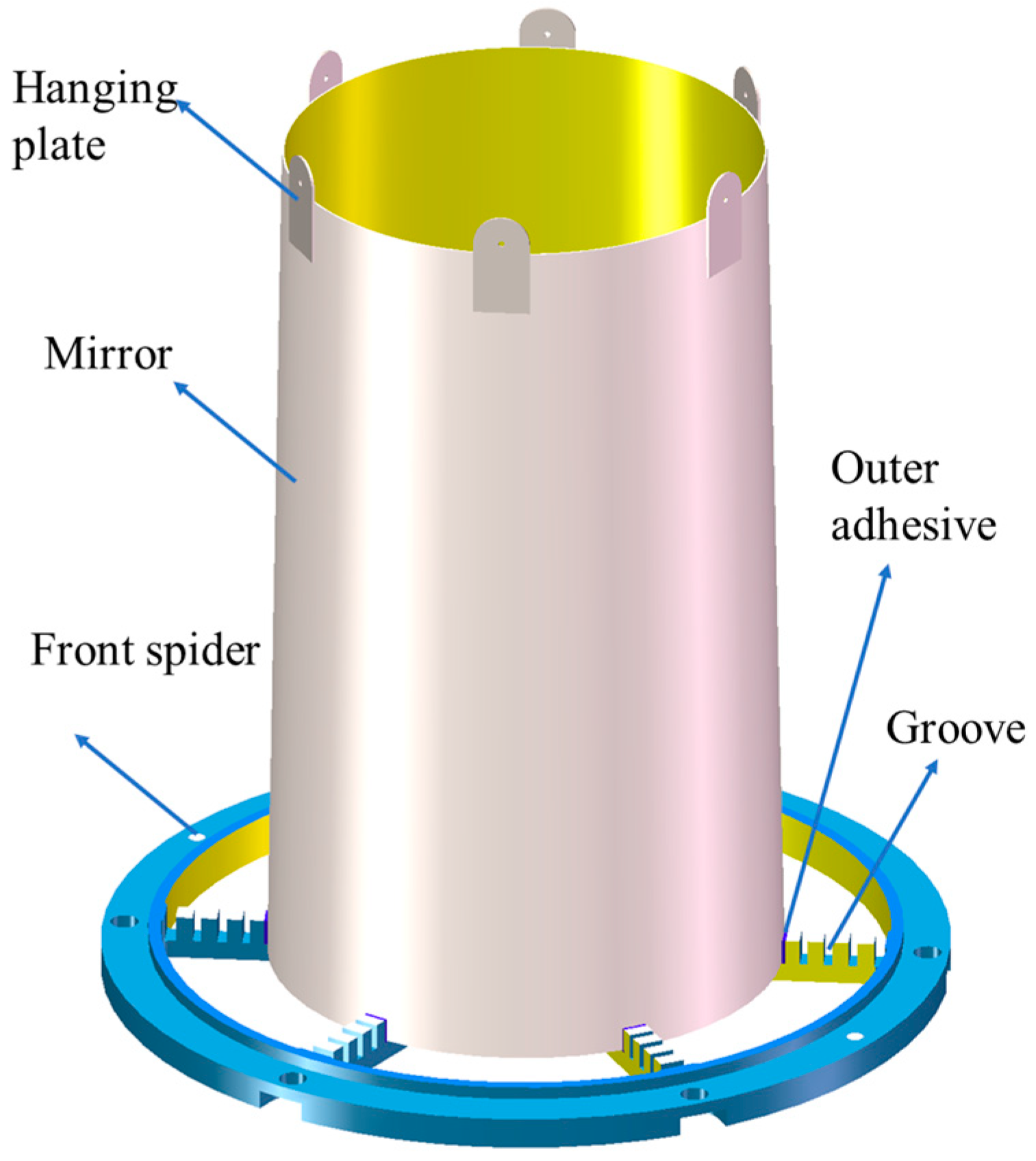
2.2. During Assembly

In the process of grazing incidence focusing mirror assembly, the upper hanging points are used to carry out the process. In this section, according to the diameter of the grazing incidence focusing mirror, two types of hanging points are used for comparison, one with three hanging points and one with six hanging points, of which three are used for adjusting the spatial position of the mirror and the other three are used for counterweight, as shown in Figure 7, which is a schematic diagram of the mirror to be assembled. In the actual assembly process, to ensure the mechanical properties, the three hanging points are used to lift the mirror at a certain vertical height, and then the spatial position is adjusted. At this time, the mirror is in suspension, and the bottom of the mirror is located in the groove corresponding to the position of the front spider. Simulation is carried out for the mirror with different numbers of hanging points in this state to analyse the influence of gravity on the accuracy of the mirror surface shape. To maintain consistency with the data of the measured point cloud in the previous section, in the process of finite-element meshing of the mirror, the form of a shell cell is used, the number of circumferential nodes is 36, and the node spacing of the busbar along the axial direction is 0.5 mm. The corresponding material parameters of the simulation are shown in Table 2, and the results of the simulation are shown in Figure 8. The nodes on the inner surface of the mirror are extracted and then reconstructed using the NURBS surface, and the imaging quality analysis of the surface shape accuracy affected by gravity is carried out and the results are shown in Figure 9. The results of the analysis of the surface shape accuracy of the mirror affected by gravity in the six-hanging-point and three-hanging-point modes are 49.50″ and 51.37″, which are decreased by about 0.86″ and 2.73″, respectively.

2.3. Post-Assembly

After the assembly is completed, the spatial position of the mirror needs to be bonded and fixed. Since the mirror is located in the corresponding groove at this time, the outer adhesive layer is located between the outer surface of the mirror and the surface of the outer groove, and the inner adhesive layer is located between the inner surface of the mirror and the surface of the inner groove, due to the difference in the curing shrinkage force of the inner and outer adhesive layers which will cause a change in the mirror’s surface shape accuracy and affect the imaging quality. Based on the accuracy of the mirror surface shape after the influence of gravity in the previous section, the comprehensive mechanical simulation model of the mirror considering the adhesive curing is established, and the simulation analysis of the adhesive layer curing shrinkage force is carried out by the equivalent linear expansion coefficient method. In order to ensure the quality of the mesh element of the adhesive layer, three layers of mesh elements along the direction of the adhesive layer thickness are set, and the circumferential nodes of the mirror are set to be 36, and the node interval in the direction of the axial busbar is 0.5 mm. We extract the nodes on the inner surface of the mirror, perform NURBS surface fitting reconstruction, build an accurate geometric digital twin model based on the characterisation of surface shape accuracy, and then analyse the focusing imaging results of the adhesive curing. The simulation results are shown in Figure 10. In order to better describe the optical simulation results of the grazing incidence focusing mirror for different conditions, the angular resolution results are shown in Table 3.

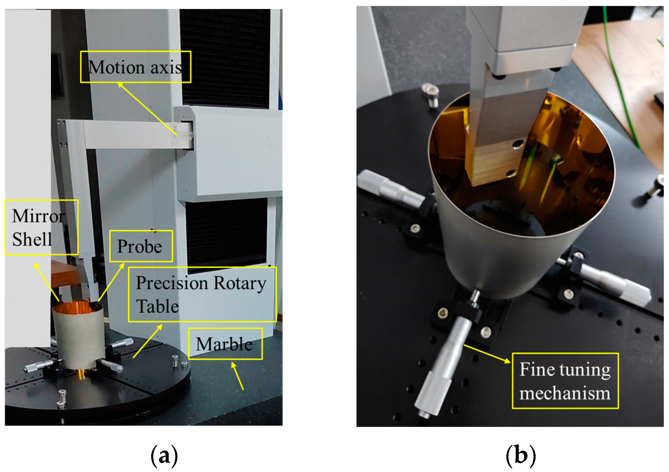
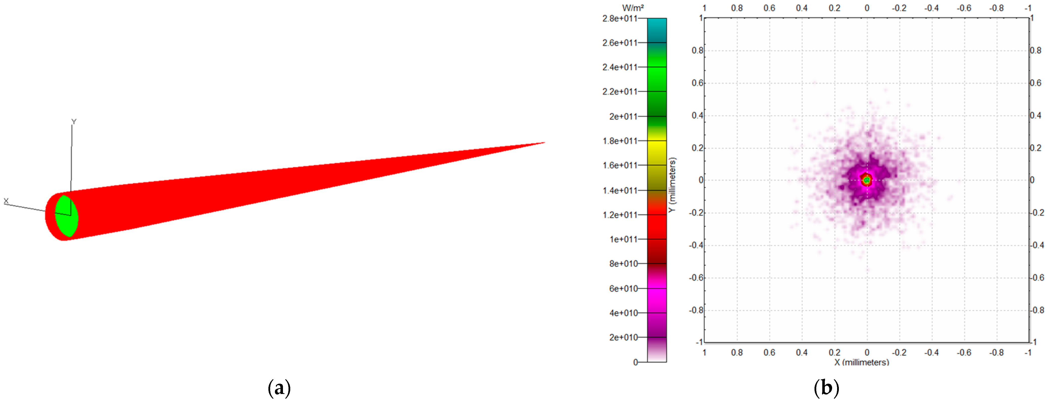
3. Experimental Verification

As shown in Figure 11, the experimental setup for verifying the assembly process of the grazing incidence focusing mirror is constructed. At the bottom is a 45-degree flat mirror, which is used to turn the parallel light emitted from the parallel light source from the horizontal direction to the vertical direction; the base of the platform is a fixed support subsystem, which mainly contains various mechanisms for adjusting and fixing the front spider to move horizontally and centrally; the upper part is a precision adjustment subsystem, which is the most crucial device for the assembly and adjustment device, and mainly consists of six circumferential uniformly arranged motion modules and a two-dimensional moving platform below, in which three of the six motion modules are connected to a piezoelectric actuator mechanism for precision adjustment of the spatial attitude of the mirror, and three of them are used as counterweights to reduce the influence of weight on the mirror’s surface shape accuracy; at the top is the spot monitoring subsystem, which mainly includes a large travelling module that can move along the vertical direction, a motorised five-degree-of-freedom adjustment stage, and a spot analyser, which is used to adapt to the precision adjustment of the focal length of the mirror, to ensure that the focused spot is accurately imaged in the image plane of the spot analyser; and on the left side is the transfer arm, which is used for the initial transfer and placement work of the mirror. The schematic diagram of the optical path of this experimental setup is shown in Figure 12.
The gravity effect experiments are carried out in the three-hanging-point and six-hanging-point modes, respectively, and the operation steps are slightly different; in the six-hanging-point suspension mode, the other three-hanging-point are counterweights, and each counterweight is 1/6 of the weight of the mirror itself. All the hanging points are evenly distributed, and the hanging plate is made of stainless steel of uniform size, which is connected to the motion module evenly distributed in the circumferential direction above through the hanging rope, and the hanging plate is connected to the mirror by double-sided adhesive. To ensure that the force of the hanging points is uniform in the assembly process, the hanging points are located at the same height relative to the mirror. The direction of the tension of the hanging rope is vertically upward, so in the process of bonding the hanging plate to the outer surface of the mirror, all the hanging points should be adjusted to a uniform corresponding position first, and then the upper motion module should be slowly moved to the outer surface of the mirror, so that the hanging points are just external to the outer side of the mirror, and then three of the hanging points should be slowly adjusted to adjust the spatial position of the mirror. The mirror under the two hanging-point methods is shown in Figure 13, the process of adjusting the experimental setup is shown in Figure 14, and the imaging quality of the focused spot is shown in Figure 15.
After the spatial position adjustment of the grazing incidence focusing mirror based on the six-hanging-point method, it is boned and cured. Considering the consistency of the adhesive layer, an automatic dispenser is used to control the amount of adhesive at each point. The six corresponding grooves on the front spider are dispensed symmetrically to reduce the effect of human dispensing on the surface shape accuracy of the mirror. We take the current glue point as the No. 1 adhesive point, clockwise in turn the points are recorded as the No. 2–No. 6 adhesive points, the order of dispensing is 1-4-2-5-3-6, and the amount of adhesive is controlled to just fill the inner and outer layer of adhesive as a principle, swabbing the excess adhesive flowing outside of the front spider’s grooves. The specific state before and after dispensing is shown in Figure 16. Then, according to the curing time of GHJ-01(Z), it will wait for its curing for 24 h at room temperature to observe the change in imaging quality due to the curing of the adhesive bonding. The imaging quality of the grazing incidence focusing mirror after 24 h when the adhesive layer is cured completely is shown in Figure 17.

4. Discussion

Observing the comparative results of simulation and experiment during the full-cycle assembly process, as shown in Table 4, the influence of the grazing incidence focusing mirror’s surface shape error on the imaging quality before assembly is a dominant factor, the influence of adhesive curing on the imaging quality is second, and gravity has the slightest impact on the imaging quality. There are some differences between the simulation results and the experimental results, and the main reasons are as follows:

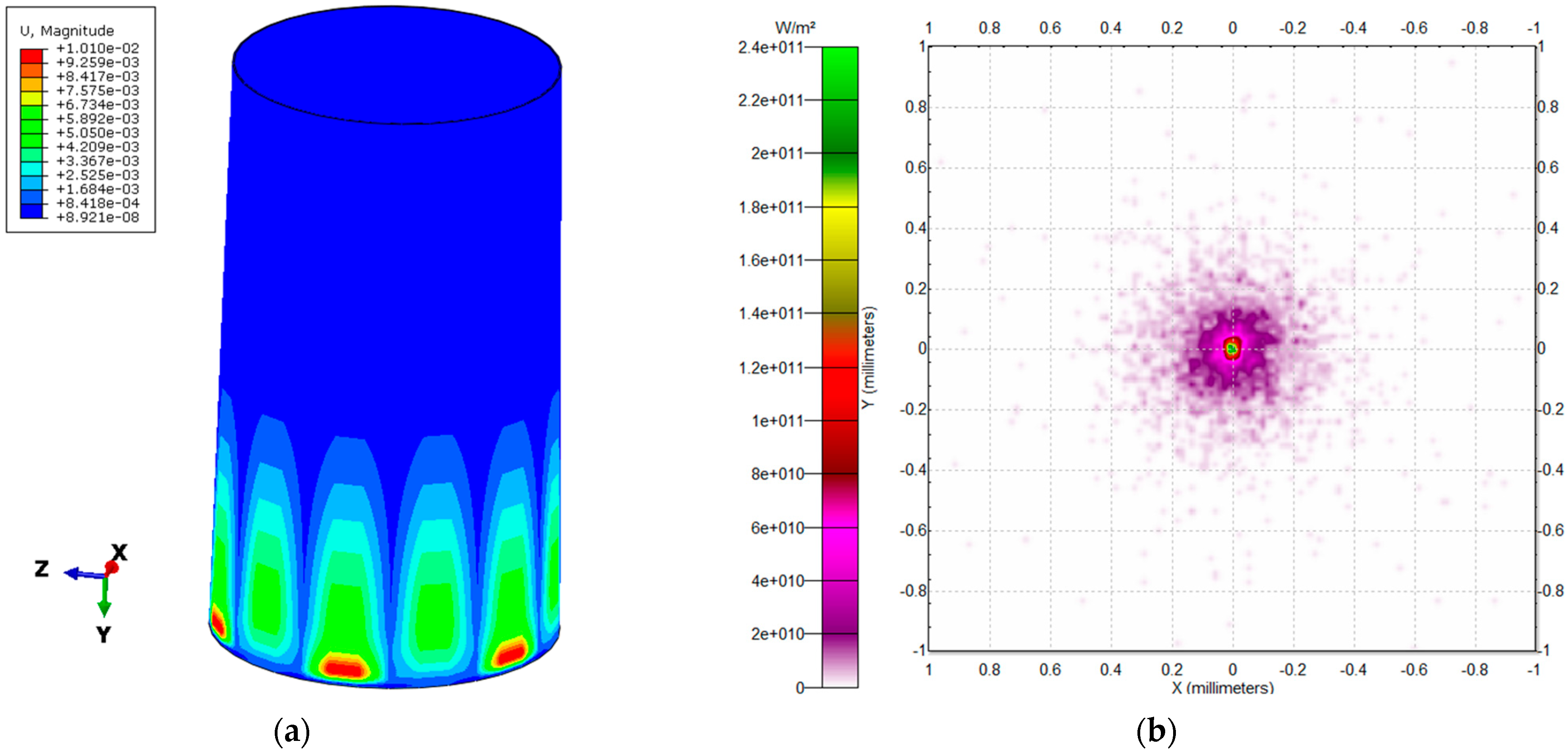
4.1. Results of the Effect of Gravity

For the effect of gravity on the imaging quality of mirror surface shape accuracy in assembly, both the experimental and simulation results show that the imaging quality is poorer in the three-hanging-point method than in the six-hanging-point method, which proves that the six-hanging-point method is more suitable for a grazing incidence focusing mirror suspension of this diameter than the three-hanging-point method that causes less change in the surface shape. However, the experimental results in both ways are more significant than the simulation results, mainly due to the following:
(1) The position of the hanging plates has an influence; although the upper motion module is arranged uniformly along the circumferential direction, the hanging plates underneath are bonded to the outer surface of the mirror due to the rotatability of the hanging plates. There are minor differences in the positions of the hanging plates bonded to the outer surface of the mirror, which influences the uniformity of the hanging points arranged on top.
(2) The spatial position of the mirror is precisely adjusted by the piezoelectric actuator so that the imaging quality of the focused spot reaches the most superior state. However, in this process, due to the slight difference between the optical axis of the mirror with surface shape error and the standard optical axis position of the ideal mirror, the spatial attitude of the mirror adjusted in the experiment is slightly different from the ideal position of the absolute perpendicularity, which leads to the changes in the imaging state of the focused spot.

4.2. Results of the Effects of Post-Assembly Adhesive Curing

The experimental results for the effect of post-assembly adhesive curing on the focusing imaging quality of mirror surface shape accuracy are more significant than the simulation results, mainly because of the following:
(1) There is a slight difference in the amount of adhesive at the six dispensing positions during the bonding and curing process; despite the strict control of the amount of adhesive discharged from the automatic dispensing machine, there is a slight difference in the actual amount of adhesive contacted by the inner adhesive, outer adhesive, and mirror at the dispensing position due to the spillage of some of the adhesive in the dispensing process, further leading to inconsistency in the amount of adhesive at the six dispensing positions, which leads to poor focusing imaging quality for the grazing incidence focusing mirror.
(2) The adhesive curing process is about 24 h at room temperature, but the constant temperature control does not guarantee absolute stability, so that the temperature difference brings about a change in the temperature-variable stress during adhesive curing, which in turn makes the imaging quality of the grazing incidence focusing mirror worse.
(3) Perturbation changes in the external environment have an effect; it has been found that during the experimental process, changes in the light intensity of the external ambient light, airflow perturbation, and environmental vibration will affect the imaging quality of the grazing incidence focusing mirror. However, it has been shown that even in the relatively dark environment, and surrounded by doors and windows which are closed tightly, the external influencing factors in the 24-hour adhesive curing process still exist, which results in the deterioration of imaging quality of the grazing incidence focusing mirror.

5. Conclusions

In this paper, we propose a method for predicting the grazing incidence focusing mirror imaging quality based on accurate modelling of the surface shape accuracy for the whole assembly process. Based on the measurement data obtained before assembly, with the suspension gravity during assembly, and adhesive curing shrinkage force after assembly, the surface shape distribution error of the inner surface of the focusing mirror is reconstructed by using the NURBS surface, then a prediction for the angular resolution of imaging quality is performed. The results show the following:
(1) The surface shape distribution error of the grazing incidence focusing mirror itself has the most significant impact on its imaging quality during the whole assembly process, and the angular resolution of the focused spot decreases by about 47″ compared with that of the ideal surface shape;
(2) The difference in the angular resolution of the focused spot between the three-hanging-point and the six-hanging-point method under the influence of gravity is about 2.11″, and the six-hanging-point mode is more suitable for the grazing incidence focusing mirror with this diameter;
(3) The adhesive curing causes a decrease in the angular resolution of the focused spot by about 4.2″.
In contrast to previous imaging quality analyses based on ideal grazing incidence focusing models, the prediction method comprehensively considers the effect of changes in the surface shape distribution error on the imaging quality caused by different influencing factors for the whole assembly process of the grazing incidence focusing mirror. It can predict the angular resolution of the mirror with different surface shape accuracy before assembly, which can effectively support the optimisation of the precision assembly process for grazing incidence focusing mirrors.

Author Contributions

Conceptualization, Z.Z. and Z.M.; methodology, E.L.; validation, T.S.; investigation, F.Z.; writing—original draft preparation, E.L.; writing—review and editing, C.L. All authors have read and agreed to the published version of the manuscript.

Funding

This research was funded by the National Natural Science Foundation of China (project No. 42327802).

Institutional Review Board Statement

Not applicable.

Informed Consent Statement

Not applicable.

Data Availability Statement

The raw data supporting the conclusions of this article will be made available by the corresponding authors on request.

Conflicts of Interest

The authors declare no conflicts of interest.

References

  1. Dong, L.Q.; Yang, L.X.; Su, Y.; Shan, R.Y. Development Trend of the Space X-Ray Detection Technology. Spacecr. Recover. Remote Sens. 2022, 43, 67–77. [Google Scholar]
  2. Civitani, M.M.; Parodi, G.; Vecchi, G.; Ghigo, M.; Basso, S.; Davis, J.M.; Elsner, R.F.; Kiranmayee, K.; Pareschi, G.; Swartz, D.; et al. Lynx x-ray optics based on thin monolithic shells: Design and development. J. Astron. Telesc. Instrum. Syst. 2019, 5, 021014. [Google Scholar] [CrossRef]
  3. Romaine, S.; Basso, S.; Bruni, R.J.; Burkert, W.; Citterio, O.; Conti, G.; Engelhaupt, D.; Freyberg, M.J.; Ghigo, M.; Gorenstein, P.; et al. Development of a Prototype Nickel Optic for the Constellation-X Hard x-Ray Telescope: IV. In Proceedings of the Space Telescopes and Instrumentation II: Ultraviolet to Gamma Ray, Orlando, FL, USA, 24–31 May 2006. [Google Scholar]
  4. Gubarev, M.; Ramsey, B.; O’Dell, S.L.; Elsner, R.; Kilaru, K.; McCracken, J.; Pavlinsky, M.; Tkachenko, A.; Lapshov, I.; Atkins, C.; et al. Development of Mirror Modules for the ART-XC Instrument Aboard the Spectrum-Roentgen-Gamma Mission. In Proceedings of the Optics for EUV, X-Ray, and Gamma-Ray Astronomy VI, San Diego, CA, USA, 26–29 August 2013. [Google Scholar]
  5. Friedrich, P.; Bräuninger, H.; Budau, B.; Burkert, W.; Eder, J.; Freyberg, M.J.; Hartner, G.; Mühlegger, M.; Predehl, P.; Erhard, M.; et al. Design and Development of the EROSITA X-Ray Mirrors. In Proceedings of the Space Telescopes and Instrumentation 2008: Ultraviolet to Gamma Ray, Marseille, France, 23–28 June 2008. [Google Scholar]
  6. Zuo, F.-C.; Mei, Z.-W.; Deng, L.-L.; Shi, Y.-Q.; He, Y.-B.; Li, L.-S.; Zhou, H.; Xie, J.; Zhang, H.-L.; Sun, Y. Development and in-orbit performance evaluation of multi-layered nested grazing incidence optics. Acta Phys. Sin. 2020, 69, 63–71. [Google Scholar] [CrossRef]
  7. Wang, B.; Yang, Y.-J.; Wang, D.-L.; Wang, L.-P.; Li, D.; Qiao, Z.; Ding, F.; Xue, J.-D.; Liao, Q.-Y. Ultra-precision manufacture of X-ray focusing mirror. Opt. Precis. Eng. 2021, 29, 1839–1846. [Google Scholar] [CrossRef]
  8. Sironi, G. Mandrels Manufacturing Processes for Ni Electroformed X-Ray Optics: Profile Errors Contribution to Imaging Degradation. In Proceedings of the Space Telescopes and Instrumentation 2008: Ultraviolet to Gamma Ray, Marseille, France, 23–28 June 2008. [Google Scholar]
  9. Wu, K.J.; Ding, F.; Wang, B.; Yang, Y.J.; Wang, Y.S.; Qiao, Z.; Li, D.; Jin, Y.; Qiang, P.F.; Zhao, Z.J.; et al. Simulation and an Experimental Study on the Optical Performance of a Wolter-I Focusing Mirror Based on a 3D Ray Tracing Algorithm. Opt. Express 2023, 31, 31533–31555. [Google Scholar] [CrossRef]
  10. Li, Y.M.; Deng, L.L.; Yang, J.; Tian, X.Y.; Zuo, F.C.; Shen, K.; Xie, J. Manufacturing Technology and Application Development of Electroformed Nickel Wolter-I Optical System. Aerosp. Control Appl. 2020, 46, 8–15. [Google Scholar]
  11. Zhang, J.W. CCD Data Processing for Dark Matter Experiments and Mounting of Domestically Produced X-Ray Focusing Mirrors. Master’s Thesis, Heilongjiang University, Harbin, China, 2020. [Google Scholar]
  12. Gubarev, M.V.; Ramsey, B.D.; Kester, T.; Speegle, C.O.; Engelhaupt, D.; Martin, G. Figure Measurements of High-Energy x-Ray Replicated Optics. In Proceedings of the Optics for EUV, X-Ray, and Gamma-Ray Astronomy, San Diego, CA, USA, 4–7 August 2004. [Google Scholar]
  13. Gubarev, M.; Ramsey, B.; Arnold, W. Alignment System for Full-Shell Replicated x-Ray Mirrors. In Proceedings of the EUV and X-Ray Optics: Synergy between Laboratory and Space, Prague, Czech Republic, 20–22 April 2009. [Google Scholar]
  14. Gubarev, M.; Arnold, W.; Benson, C.; Kester, T.; Lehner, D.; Ramsey, B.; Upton, R. Mounting and Alignment of Full-Shell Replicated x-Ray Optics. In Proceedings of the Optics for EUV, X-Ray, and Gamma-Ray Astronomy III, San Diego, CA, USA, 26–27 August 2007. [Google Scholar]
  15. Li, L.S.; Mei, Z.W.; Deng, L.L.; Lü, Z.X.; Liu, J.H.; Sun, J.B.; Sun, Y.; Zhou, H.; Zuo, F.C. Assembly Error Analysis and In-Orbit Verification of Grazing Incidence Focusing X-Ray Pulsar Telescope. J. Mech. Eng. 2018, 54, 49–60. [Google Scholar] [CrossRef]
  16. Ramsey, B.D.; Bongiorno, S.D.; Kolodziejczak, J.J.; Kilaru, K.; Alexander, C.; Baumgartner, W.H.; Breeding, S.; Elsner, R.F.; Le Roy, S.; McCracken, J.; et al. Optics for the imaging x-ray polarimetry explorer. J. Astron. Telesc. Instrum. Syst. 2022, 8, 024003. [Google Scholar] [CrossRef]
  17. Bongiorno, S.D.; Kolodziejczak, J.J.; Kilaru, K.; Eng, R.; Stahl, M.T.; Baumgartner, W.H.; Thomas, N.E.; Ranganathan, J.; Ramsey, B.D.; Tucker, J.M. Assembly of the IXPE Mirror Modules. In Proceedings of the Optics for EUV, X-Ray, and Gamma-Ray Astronomy X, San Diego, CA, USA, 1–5 August 2021. [Google Scholar]
  18. Roche, J.M.; Gubarev, M.V.; Smith, W.S.; O’Dell, S.L.; Kolodziejczak, J.J.; Weisskopf, M.C.; Ramsey, B.D.; Elsner, R.F. Mounting for Fabrication, Metrology, and Assembly of Full-Shell Grazing-Incidence Optics. In Proceedings of the Space Telescopes and Instrumentation 2014: Ultraviolet to Gamma Ray, Montréal, QC, Canada, 22–26 June 2014. [Google Scholar]
  19. Roche, J.M.; Kolodziejczak, J.J.; O’Dell, S.L.; Elsner, R.F.; Weisskopf, M.C.; Ramsey, B.; Gubarev, M.V. Opto-Mechanical Analyses for Performance Optimization of Lightweight Grazing-Incidence Mirrors. In Proceedings of the Optics for EUV, X-Ray, and Gamma-Ray Astronomy VI, San Diego, CA, USA, 26–29 August 2013. [Google Scholar]
  20. Li, L.S.; Qiang, P.F.; Sheng, L.Z.; Liu, Z.; Zhou, X.H.; Zhao, B.S.; Zhang, C.M. Development and Testing of Glass Substrate Wolter-1 X-Ray Focusing Mirror. Acta Phys. Sin. 2018, 67, 1–6. [Google Scholar]
  21. Civitani, M.M.; Basso, S.; Citterio, O.; Conconi, P.; Ghigo, M.; Pareschi, G.; Proserpio, L.; Salmaso, B.; Sironi, G.; Spiga, D.; et al. Accurate integration of segmented x-ray optics using interfacing ribs. Opt. Eng. 2013, 52, 091809. [Google Scholar] [CrossRef]
  22. Zhang, X.; Wang, J.; Zhang, Y.; Yang, Y.J.; Chen, Y.; Wen, J. Numerical Study on Thermal Deformation of Wolter-I Focusing. Acta Photonica Sin. 2020, 49, 0512002. [Google Scholar] [CrossRef]
  23. Liu, J.; Yang, H.B.; Gong, Y.; Yuan, W.Q. Analysis of Surface Figure Error at Different Curing Time on Bonding Structure of Optical-Mechanical System. Opto-Electron. Eng. 2011, 38, 140–145. [Google Scholar]
  24. Li, W.J.; Wang, S.X.; Mu, Q.Q.; Yang, C.L.; Xuan, L. Using the Equivalent Stress to Analyze the Effect of Temperature Change on Surface Accuracy of the Bonded Mirror. Acta Photonica Sin. 2015, 44, 1212001. [Google Scholar]
  25. Dong, D.Y.; Li, Z.L.; Li, R.G.; Fan, Y.C.; Zhang, X.J. Simulation and Experiment of Influence of Adhesive Curing on Reflective Mirror Surface. Opt. Precis. Eng. 2014, 22, 2698–2707. [Google Scholar] [CrossRef]
  26. Hao, C.Y.; Qiu, S.H.; Pan, W.T.; Li, F.; Yan, Y.; Guan, X.F. Integrated Modeling and Simulation of X-Ray Focusing Telescope in Mounting Process. J. TONGJI Univ. 2020, 48, 602–609. [Google Scholar]
  27. Wang, S.; Yi, S.Z.; Wang, X.; Mu, B.Z. Analysis of X-Ray Focusing Telescope Structure Based on Finite Element Method. Opt. Instrum. 2015, 37, 441–446. [Google Scholar]
  28. Zhao, Z.J.; Wang, Y.; Zhang, L.Y.; Chen, C.; Ma, J. Experiments and Simulation of X-Ray Optical Wolter-I Focusing Mirror. Opt. Precis. Eng. 2019, 27, 2330–2336. [Google Scholar] [CrossRef]
  29. Liu, P.; Chen, B.; Zhang, Y.C.; He, L.P.; Wang, X.D. Imaging Quality Evaluation of Soft X-Ray Grazing Incidence Telescope. Opt. Precis. Eng. 2019, 27, 2136–2143. [Google Scholar]
  30. Mu, B.Z.; Liu, H.Y.; Jin, H.J.; Yang, X.J.; Wang, F.F.; Li, W.B.; Chen, H.; Wang, Z.S. Optimization of geometrical design of nested conical Wolter-I X-ray telescope. Chin. Opt. Lett. 2012, 10, 103401–103404. [Google Scholar] [CrossRef]
  31. Suszyński, M.; Peta, K.; Černohlávek, V.; Svoboda, M. Mechanical Assembly Sequence Determination Using Artificial Neural Networks Based on Selected DFA Rating Factors. Symmetry 2022, 14, 1013. [Google Scholar] [CrossRef]
  32. Zhang, Z.; Zhang, Z.; Jin, X.; Zhang, Q. A Novel Modelling Method of Geometric Errors for Precision Assembly. Int. J. Adv. Manuf. Technol. 2018, 94, 1139–1160. [Google Scholar] [CrossRef]
Figure 1. (a) Measurement process; (b) Local zoomed in view.
Applsci 14 06242 g001
Figure 2. The whole reconstruction process: (a) Original measurement point cloud; (b) Original measurement point cloud mesh surface; (c) Interpolated mesh surface; (d) NURBS surface reconstruction surface.
Applsci 14 06242 g002
Figure 3. Busbar radial change values.
Applsci 14 06242 g003
Figure 4. Mirror with surface shape error on the inner surface.
Applsci 14 06242 g004
Figure 5. (a) Standard surface shape simulation; (b) Standard surface shape simulation with NURBS surface interpolation.
Applsci 14 06242 g005
Figure 6. (a) Simulation of mirror optical path with surface shape error; (b) Simulation results.
Applsci 14 06242 g006
Figure 7. Schematic of the model of the mirror.
Applsci 14 06242 g007
Figure 8. (a) Three-hanging-point simulation results; (b) Six-hanging-point simulation results.
Applsci 14 06242 g008
Figure 9. Results of the analysis of the accuracy of the mirror surface shape affected by gravity: (a) three-hanging-point; (b) six-hanging-point.
Applsci 14 06242 g009
Figure 10. (a) Effect of adhesive curing on the surface shape of the mirror; (b) Analysis of the accuracy of the surface shape of the mirror due to adhesive curing.
Applsci 14 06242 g010
Figure 11. Experimental setup for grazing incidence focusing mirror assembly.
Applsci 14 06242 g011
Figure 12. Schematic diagram of the optical path of the grazing incidence focusing mirror.
Applsci 14 06242 g012
Figure 13. Focusing mirror in two forms of hanging points: (a) three-hanging-point; (b) six-hanging-point.
Applsci 14 06242 g013
Figure 14. (a) Precision adjustment subsystem; (b) Experimental setup.
Applsci 14 06242 g014
Figure 15. (a) Focused spot in three-hanging-point form; (b) Angular resolution in three-hanging-point form; (c) Focused spot in six-hanging-point form; (d) Angular resolution in six-hanging-point form.
Applsci 14 06242 g015
Figure 16. (a) Before dispensing; (b) During dispensing; (c) Outside of mirror after dispensing; (d) Inside of mirror after dispensing.
Applsci 14 06242 g016
Figure 17. (a) Imaging quality after 24 h of adhesive layer curing; (b) Angular resolution.
Applsci 14 06242 g017
Table 1. Mirror design parameters.
ParameterRmaxRminR0MassThicknessLength
Value40.6683 mm38.1126 mm0.71909 mm0.12335 kg0.4 mm140 mm
Table 2. Material parameters.
MaterialYoung’s Modulus
(Mpa)
Poisson’s RatioDensity
(t/mm3)
Equivalent Linear Expansion
Coefficient (α/°C−1)
Hanging plate—
Stainless Steel
210,0000.37.85 × 10−90
Mirror—Ni207,0000.318.9 × 10−90
Adhesive—GHJ-01(Z)158.620.4951.22 × 10−90.0066
Front spider—
Stainless Steel
210,0000.37.85 × 10−90
Table 3. The angular resolution under different conditions.
Assembly ProcessAngular Resolution
Standard surface (error-free)1.23″
Standard surface with NURBS surface interpolation (error-free)1.51″
Pre-assembly (with surface shape error)48.64″
During assembly (three-hanging-point)51.37″
During assembly (six-hanging-point)49.50″
Post-assembly (after adhesive curing)52.23″
Table 4. Comparison of image quality of focusing mirror by angular resolution.
Assembly ProcessSimulation ResultsExperimental Results
During assembly
(three-hanging-point)
51.37″56.76″
During assembly
(six-hanging-point)
49.50″54.65″
Post-assembly52.23″58.86″
Disclaimer/Publisher’s Note: The statements, opinions and data contained in all publications are solely those of the individual author(s) and contributor(s) and not of MDPI and/or the editor(s). MDPI and/or the editor(s) disclaim responsibility for any injury to people or property resulting from any ideas, methods, instructions or products referred to in the content.

