Abstract
Quality assurance (QA) ensures the accurate and safe delivery of radiation treatment. However, there are several challenges for advanced radiotherapy techniques, such as stereotactic radiosurgery (SRS), where substantial doses of radiation with multi-directional beams and variable dose rates are delivered to specific areas. Current dosimeters lack high precision, exhibiting issues with dependency on the angle of measurement and the dose rate. This study investigates the characterization of a two-dimensional edgeless silicon diode array for QA in SRS. This detector underwent evaluation of its dose linearity, percentage depth dose (PDD), output factors (OFs), dose rate variability, and angular dependence with megavoltage linear accelerator beams. The edgeless array demonstrated a linear response in the direct detection of MV therapeutic X-rays with sensitivity of 6.95 × 10⁻³ ± 2.3 × 10⁻⁵ Gy/nC, and the percentage differences for PDD and OF measurements were found to be within 2% compared to the reference detector. A dose per pulse dependence of ±2% was demonstrated across the range of 0.12 to 0.39 mGy/pulse. The angular dependence was within 2% variation for irradiation angles greater than 80° and smaller than 120°; however, a maximum of 4% variation was observed with some diodes for angles between 80° and 120°. The improved performance of the edgeless array is likely to overcome limitations of the current dosimeters for SRS QA by operating without the need of any corrections.
1. Introduction
Stereotactic radiosurgery, often performed on linear accelerators, and GammaKnife® (Elekta AB, Stockholm, Sweden), CyberKnife® (Accuray Incorporated, Sunnyvale, CA, USA), and Tomotherapy® (Accuray Incorporated, Sunnyvale, CA, USA) machines, is used to treat both cancerous and functional brain conditions [1,2,3] by delivering high-dose radiation ranging from 20 to 100 Gy per treatment fraction. Because of the hypofractionation regime used in this modality, ensuring accurate delivery is crucial for achieving the desired clinical outcomes and preventing severe side effects, particularly when treating sensitive areas such as the trigeminal nerve and other ganglia, the thalamus, the hypothalamus, and the hippocampus [4,5].
Moreover, multiple brain metastases have been treated with single-isocenter stereotactic irradiation, employing a singular set of arcs to simultaneously target multiple lesions. This approach yields favorable outcomes in terms of local control rate while minimizing the risk of neurocognitive deterioration and leukoencephalopathy [6,7,8]. The implementation of single-isocenter stereotactic irradiation involves numerous complex factors that require comprehensive commissioning measurements, end-to-end testing, and patient-specific QA procedures [9]. Variations in skull positioning or collimator angle during rotation may result in large geometric discrepancies as the distance between the target and the isocenter increases. Robust QA procedures become increasingly crucial to avoid the errors related to this new delivery technique [10]. However, the effectiveness of QA procedures is hindered by the inadequacy of efficient and accurate equipment, in particular radiation dosimeter arrays.
Treatment with narrow radiation fields and doses ranging from 20 to 100 Gy per fraction with collimated beams from 0.5 to 3 cm in diameter, compared to 2 to 5 Gy per fraction in conventional radiotherapy, requires that the target position and delivered dose are accurately determined [1,5,11]. These extreme forms of radiotherapy require small-field dosimetry which is known for its intrinsic uncertainties due to the partial occlusion of the primary source, the lack of lateral charged particle equilibrium, and the volume averaging in the dosimeter’s sensitive volume [12,13,14,15]. The complexity of performing accurate small-field dosimetry also arises from the detectors available commercially. Standard fabrication technologies for solid-state detectors adopted for small-field dosimetry are still very limited due to their dimensions in relation to the radiation field and their large angular dependence [16,17].
The currently available detectors do not meet all the critical requirements of a dosimeter for SRS, such as minimal dose rate and angular dependence, requiring several different detectors to be utilized for different type of measurements or in combination by using the technique named daisy-chaining [12,18].
Gafchromic films such as EBT3 are recommended for patient-specific QA in CyberKnife® since it is directionally independent with a high spatial resolution and tissue equivalent response in MV photon irradiation [19,20,21]. However, it does not have a linear response and its reproducibility is limited for doses ranging from 0.01 Gy to 30 Gy, which is insufficient for measuring doses used in treating brain functional diseases as the detector is required to measure doses up to 100 Gy. Films also involve extensive time for development after exposure (approx. 24 h). In addition, the establishment of a consistent method for interpreting dose readings is critical [19,20].
Recent advancements in commercial solid-state dosimeters, such as SRS MapCHECK [22], Octavius 1600 SRS [23], and IBA myQA SRS [24], offer detector arrays which provide a consistent response in megavoltage photon beams regardless of energy, small sensitivity, and small sensitive volumes. Compared to Gafchromic films, they are more sensitive to ionizing radiation and have a wider dynamic range, as well as the ability to provide real-time measurements. However, for accurate dose measurements, several correction factors are needed. They exhibit angular dependence and are influenced by dose rates [25]. Since they are usually fabricated on silicon substrates, their responses are subject to depth and field-size dependencies, which stem from the perturbations introduced to electron and photon fluences by their sensitive volumes and extra-cameral materials used for packaging [26,27]. The angular dependency of commercial solid-state detectors can affect the response by up to 25% in a range of angles from 0 to 90 degrees [28], and correction factors are needed to compensate for the angular dependency of the sensor. However, this has proven ineffective in robotic SRS or for non-coplanar arc deliveries [29].
Accurate correction factors to mitigate energy, dose rate, and angular dependence of a detector rely on multiple factors such as detector design, LINAC head design, beam quality, field size, and type of collimation, which often can be evaluated only by Monte Carlo simulations. This task can be laborious and also involves the use of information from the machine manufacturers often not available to the public [12]. Therefore, developing a technology that is correction-free is desirable as this would simplify the QA procedures and improve reliability and accuracy of the measurements.
A new technology was subjected to experiments by CERN in 2015 for manufacturing detectors with 3D PIN junctions for high energy physics ionizing radiation. The methodology proposed has been investigated by the Centre of Medical Radiation Physics (CMRP) as a potential solution to overcome the intrinsic angular dependence of planar silicon diodes when used as dosimeters. The new technological platform is named “edgeless silicon diodes” and utilizes thin floating-zone silicon substrates to manufacture single diodes with three-dimensional junctions. Individual diodes are separated from the wafer through an ion-coupled plasma etching method, and the 3D junction is created by an innovative lateral ion implantation technique [30,31].
The effectiveness of the single edgeless diodes was confirmed for QA of CyberKnife® robotic stereotactic radiosurgery. The results demonstrated that they performed efficiently without requiring adjustments for angular dependence [28].
A clinical application for the single edgeless diodes in a study of dose escalation for patient-specific QA of functional brain diseases treated by CyberKnife [17] confirmed that the edgeless diodes performed well in verifying the dose specifically tailored for each patient on a set of 10 patients, especially in cases where very high doses are administered, but also highlighted the limitation of having single dose point measurements in assessing the quality of a treatment delivery.
This study aimed to assess the feasibility of using single edgeless diodes assembled in a 2D array using an advanced tissue-equivalent bonding technique and verifying that such an array of silicon diodes can perform 2D small-field dosimetry with acceptable accuracy on a plane without the need for correction factors.
2. Materials and Methods
The 2D array proposed in this study is composed of 5 × 5 edgeless diodes assembled using the “drop-in” tap-bonding technique patented by CMRP. Drop-in bonding allows connection of the individual diodes to a polyimide tail (Kapton) using only an aluminum flexible carrier [32]. A single edgeless diode consists of a p+ top implantation and p-type substrate with a 1 × 1 mm2 area and 100 μm substrate thickness. Its cross-section is shown in Figure 1. The center-to-center distance between pixels is 3 mm and 5 mm horizontally and vertically, respectively. A sketch and photo of the array are reported in Figure 2.
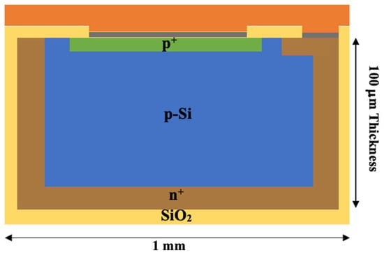
Figure 1.
A schematic representation of the edgeless diode cross-section. The diode consists of a p-Si substrate encased by phosphorous implantation (n+), while an ohmic contact at the top is created through boron implantation (p+). A 250 μm layer of SiO2 serves as passivation, with an additional 100 μm of aluminum (grey) contacts deposited on top. To protect the diode, a 500 μm layer of polyimide (orange) is applied. Not to scale.
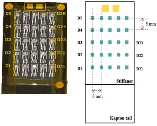
Figure 2.
The image on the left depicts the edgeless array, featuring 25 diodes, while the labels of the diodes are shown on the sides of the detector tail. On the right side, the dimensions of the array are illustrated, showing the horizontal pitch of 3 mm and a vertical pitch of 5 mm. Not to scale.
The channels are identified from D1 to D25 from the bottom left side to the top right side, as illustrated in Figure 2. Notably, the central diode is identified as D13. These diodes are securely integrated within a recess housed in a Kapton substrate. The use of Kapton offers mechanical protection, flexibility, and tissue equivalence of the extra-cameral material surrounding the sensitive volume.
A multichannel electrometer is used to read out and convert the accumulated charge of the edgeless diodes to a digital signal without dead-time or the need for external synchronization [33]. A graphical user interface visualizes the 25 channels in the appropriate 2D geometry, providing an instantaneous charge for each frame of acquisition, a total integral map, and an instantaneous current generated in each pixel. For further details about the multichannel electrometer and the graphical user interface, refer to the Supporting Information.
The data for this study were collected using linear accelerators (LINACs), specifically a Varian Clinac 21iX at the Shoalhaven Cancer Care Centre (SCCC) in Nowra (NSW, Australia) and a Varian TrueBeam at the St George Hospital Cancer Care Centre in Sydney (SGHCC). The experiments were all performed by delivering a total of 100 MU at a nominal rate of 600 MU/min using 6 MV photon beams unless otherwise indicated.
The central diode of the edgeless array was precisely aligned with the incoming beam on a 10 × 10 cm2 field collimated by open-field jaw Flattening Filtered (FF) beams.
2.1. Dose Linearity
Linearity measurements were conducted at both the SCCC and SGHCC facilities using a solid water phantom.
For the SCCC measurements, the evaluation was conducted under standard conditions, at 1.5 cm depth and source-to-surface distance (SSD) of 100 cm. Dose linearity was assessed over a range from 50 MU (50 cGy) to 500 MU (500 cGy).
On the contrary, at SGHCC, an isocentric setup was used. The array was positioned within a polymethyl methacrylate (PMMA) adapter, which has a thickness of 5 cm. Measurements were performed at a depth of 10 cm with an SSD of 90 cm, resulting in an isocentric setup with a source-to-axis distance (SAD) of 100 cm. Dose linearity was evaluated from 25 MU (19.3 cGy) to 500 MU (386.4 cGy).
The charge collected by the central diode was plotted against the received dose and the sensitivity in Gy/nC was determined by employing a least-squares fitting method. The measurements were determined based on three repetitions to assess the detector response’s uncertainty.
2.2. Dosimetry for Therapeutic X-ray Beams
2.2.1. Percentage Depth Dose (PDD)
PDD measurements in both the build-up and fall-off regions were conducted at the SCCC. The measurements were taken at varying depths, ranging from 0 cm to 25 cm in solid water, by placing the solid water slabs upstream of the array with 10 cm backscatter positioned downstream and an SSD of 100 cm.
The measurements were normalized to the response at dmax (1.5 cm depth, reference conditions). The diode’s response for depths greater than dmax was compared to relative dosimetry measurements obtained using a PTW 30013 Farmer Ionization Chamber (IC) (PTW Freiburg GmbH, Freiburg, Germany). However, measurements at depths smaller than dmax were compared to GEANT4 simulations as Farmer ICs are not well suited for accurately measuring PDD at shallow depths.
Effective Point of Measurement (EPOM)
The PDD measurement taken at a depth of 0 mm is not a real surface measurement. Approximately 500 μm of aluminum and polyimide overlayers (Kapton) covers the diode, so the effective water equivalent depth of the point of measurement of the array was calculated. The EPOM was determined for a 10 × 10 cm2 field in the build-up region with the edgeless array and was compared to Monte Carlo calculations obtained from GEANT4 simulations of the LINAC model. The data and details of the simulation have been published previously in another work from our research group and details of the simulation setup are available in [34]. The EPOM was calculated using the least-squares method, where the EPOM Δz was used as the fit parameter.
where Dg(zi) and Dw (zi) represent the relative doses at depth zi for the edgeless array and reference measurements, respectively [35]. is the uncertainty in the reference data, which was obtained according to the procedure in [34], and is the uncertainty in the edgeless array dose, which was derived from the standard deviation of 3 repetitions at each depth. The ki value was determined by multiplying the stopping power ratio and correction factors that account for perturbations of ideal cavity theory and N corresponds to the number of measurements in the PDD curve [36]. Values of Δz were evaluated between 0.06 cm and 0.09 cm in steps of 3 μm. Cubic spline interpolation was used to obtain the water depth dose (z) for any z. For each value of the depth shift Δz, χ2 was recalculated until a minimum was found using a least-squares quadratic fit. The uncertainty in the EPOM was calculated by setting confidence limits (95.5%) on the value of minimum [37].
2.2.2. Output Factor
The OF was determined by comparing the dose per MU received by the central pixel at a specific field size to the dose per MU received at a 10 × 10 cm field size. The measurement was conducted with a Varian CLINAC 21iX at the SCCC by positioning the edgeless array at a depth of 10 cm within a 30 × 30 cm2 solid water phantom and with 10 cm of solid water positioned downstream for backscattering, with an SSD of 90 cm (isocenter).
The alignment of the central pixel of the field was obtained using a dual-axis stepper motor stage. This stage utilizes Standa 8MT200 (Slovenia) series stepper motors (Standa Ltd., Vilnius, Lithuania), offering sub-micron 2D positioning accuracy within the field. The beam was aligned with the central diode by conducting a scan using a field size of 5 × 5 mm2. The detector was shifted in the x and y directions using a stepper motor, with steps of 100 µm, until the sensor’s response was maximized. The central diode was then centered in the position of the maximum measurement.
The integral charge measured by the central pixel was recorded for field sizes ranging from 0.5 × 0.5 cm2 up to 20 × 20 cm2. The measurements were determined based on three repetitions to assess the detector response’s uncertainty.
The performance of the detector was benchmarked against the response of the CC13 IC (IBA Dosimetry, Schwarzenbruck, Germany) with sensitive volume of 0.13 cm3, for field sizes larger than 3 × 3 cm2, and against the CC04 IC (IBA Dosimetry, Schwarzenbruck, Germany) with sensitivity volume of 0.04 cm3, for smaller fields to prevent the volume average effects of the CC13 IC. The edgeless array response was also compared to Gafchromic film (EBT3—ASHLAND, Wayne, NJ, USA), extracted from [31]. The measurement in this study was conducted using the same LINAC machine and with the same setup. The 20 × 20 cm2 EBT3 films were scanned with an A3 flatbed scanner (Epson Expression 10000XL (Epson, Suwa, Nagano, Japan)) in 48-bit RGB color mode. However, only the red channel was utilized for converting optical density to dosage.
2.2.3. Dose per Pulse
Dose per Pulse (DPP) was evaluated by delivering 100 MU at a constant depth but with varying SSD. By doing so, the DPP received by the array varies by the inverse square law. This technique allows for adjusting the instantaneous dose rate for each pulse of the LINAC without affecting the timing structure of the pulses [38]. The LINAC was set to a nominal dose rate of 600 MU/min and pulse rate of 360 Hz, corresponding to an instantaneous dose of 2.78 × 10⁻⁴ Gy/pulse under reference conditions.
The experimental measurements were conducted utilizing a Varian TrueBeam LINAC at the SGHCC facility. SSD was varied from 83.5 cm to 328.5 cm. The LINAC head was oriented at 90 degrees (horizontally) and the phantom surface was placed vertically with the detector facing the gantry head. The edgeless array was placed within a PMMA adapter at a 3.5 cm depth and 7 cm of solid water was added downstream to account for backscatter effects.
The PTW 0.6cc TM30013 IC was used to measure the dose rate at each SSD value, and the same conditions and depth were used for the edgeless array. These measurements encompassed a range of incident dose rates, spanning from 0.025 mGy per pulse to 0.39 mGy per pulse. A PTW Unidos electrometer was employed to read the IC’s output, providing the total charge accumulated while applying +300 V to the central electrode.
The responses of the edgeless array and ICs were normalized to reference conditions (100 cm SAD), corresponding to 2.78 × 10⁻⁴ Gy/pulse. These normalized responses were then graphed as the ratio of the normalized responses of the edgeless array to the IC, with the DPP serving as the independent variable. With the assumption that the DPP dependence of the IC falls within a range of ±1% [39], any deviation above this quantity between the edgeless array and the IC responses would suggest the presence of DPP dependencies in the edgeless array. The DPP measurement for the edgeless array was also compared to measurement acquired from edgeless detectors employing an n-type substrate (NN), where the bulk substrate is of the n-type, featuring a p+ lateral junction and an n+ junction positioned at the top [40]. This architecture is selected for comparative analysis due to its establishment of identical junctions with the dopant species merely being inverted.
2.2.4. Angular Dependence
The angular dependence of the edgeless array was assessed as a function of the angle between the beam and the array plane over a range spanning from 0° to 180°, achieved by rotating the LINAC gantry while keeping the detector in a fixed position. The setup of the experiment is illustrated in Figure 3. When the gantry was rotated 90° (aligned along the X-axis), the edgeless array was facing the beam. This setup allowed measurements for angles between the beam and the array plane to vary between 0° and 180°, avoiding the patient couch from generating any distortion of the beam.
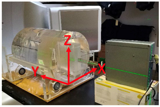
Figure 3.
The experimental setup for the angular dependence study. The edgeless array is enclosed within a PMMA adaptor facing the beam direction (X-axis) at 0° (gantry angle is 90°). The incident beam is striking the array’s edge at 90° (Z-axis) when the beam is directed towards the floor.
The edgeless array is placed at a 15 cm depth in a cylindrical phantom having a 30 cm diameter and 40 cm length, and made of PMMA, which is described in previous studies [30,31,41]. Precise positioning of the central diode was achieved at the isocenter of the LINAC using a computed tomography (CT) scan.
To facilitate accurate dose calculations, a computed tomography (CT) scan of the cylindrical phantom, which included a detector probe without mounting the diodes, was conducted. This CT scan served the dual purpose of providing relative electron density information for dose computations and aligning the central diode precisely with the isocenter of the LINAC. The CT scan was executed at a voltage of 120 kVp with an exposure setting of 450 (mAs). The field of view spanned 600 mm, and the CT slices were configured at a thickness of 1 mm.
The doses detected by each edgeless diode were then normalized by dividing them by the corresponding dose values provided by the Varian Eclipse Treatment Planning System (TPS), employing the Acuros XB algorithm (version 15.6) as the reference.
3. Results
3.1. Dose Linearity and Sensitivity to MV X-rays
Irradiations revealed a linear response within a dose range of 25 to 500 cGy for the central pixel of the edgeless diode array. This linearity was confirmed with a coefficient of determination R2 =1. Figure 4 shows the linearity measurement at SCCC. The result obtained at SGHCC is shown in Figure S2 in the Supporting Information.
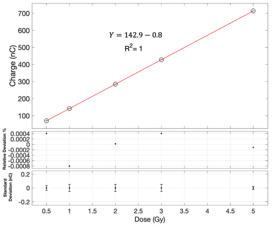
Figure 4.
Dose linearity assessment for the central diode as measured on the Clinac 21iX at SCCC. Error bars are contained within the symbols. The first subplot shows the relative deviation of each measurement from the linear fit as a function of the dose. The second subplot is the error bars which are based on the standard deviation of three measurements with the edgeless array at each dose.
The sensitivity measurements for diode D13 at the SCCC LINAC yielded a value of 7.0 × 10⁻³ ± 1.7 × 10⁻⁶ Gy/nC, while the sensitivity at SGHCC was found to be 6.728 × 10⁻³ Gy/nC. On average, across all diodes, the sensitivity for the SCCC LINAC was 6.95 × 10⁻³ ± 2.3 × 10⁻⁵ Gy/nC, whereas for SGHCC, it was 6.726 × 10⁻³ ± 1.4 × 10⁻⁵ Gy/nC.
Despite the measurements being taken in two different radiation facilities, from two different LINACs, the calibration factors registered by the sensor were found to be in close agreement, differing by only 3.6%.
3.2. Dosimetry for Therapeutic X-ray Beams
3.2.1. Percentage Depth Dose (PDD)
The measurements of the central pixel of the edgeless array are depicted in Figure 5. The obtained results are benchmarked with the measurement of the PTW 30013 Farmer IC in a solid water phantom for depths exceeding dmax = 1.5 cm and to GEANT4 simulations for the build-up region. Measurements were normalized based on measurement at dmax.
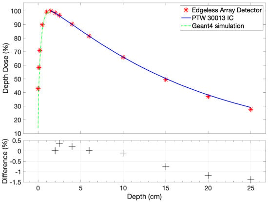
Figure 5.
The PDD measurement for the central pixel of the edgeless array, considering variations in thickness without accounting for the EPOM. The dependencies of PDD are systematically compared with the PTW 30013 Farmer IC measurement downstream of the dmax and the GEANT4 simulation [34] upstream of dmax.
The edgeless output exhibits consistency with the IC within 1.4% for depths larger than dmax. Notably, a marginal systematic under-response is discerned at greater depths, with the most pronounced discrepancy observed at 25 cm in solid water, amounting to −1.38%. In order for the detector to accurately estimate the PDD in the build-up region, an estimation of the EPOM is required.
Effective Point of Measurement
The examination of the build-up region of the PDD is shown in Figure 6 compared to the GEANT4 prediction. The EPOM that minimizes the χ2 variable in Equation (1) and calculated for the central pixel was determined to be Δz = 789 ± 46 μm. The measurement at dmax is excluded from this analysis, presuming the PDD to be 100% at this depth.
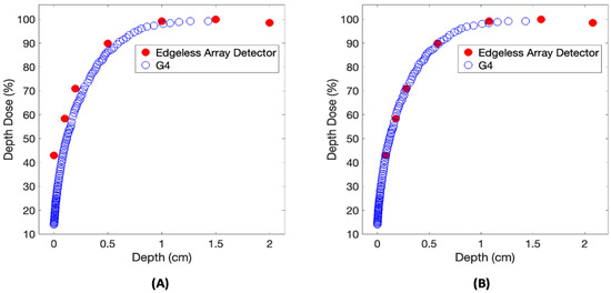
Figure 6.
A comparison of the build-up region of the PDD relative to the reference GEANT4 calculation. The PDD dataset is examined both before (A) and after (B) the implementation of a 789 μm shift.
3.2.2. Output Factor
The OF for the edgeless array is presented in Figure 7. A slight under-response is evident at smaller field sizes in comparison to both reference detectors, showing as a −2% discrepancy at 4 × 4 cm2. Conversely, an over-response of 3.6% is noted at 0.5 × 0.5 cm2 compared to EBT3. Notably, for field sizes exceeding 10 × 10 cm2, an identifiable over-response is observed in relation to IC measurements, reaching up to 3% when the jaws are expanded to 20 × 20 cm2.
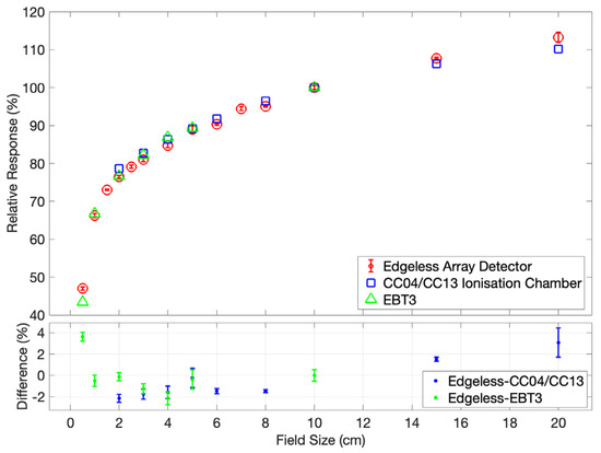
Figure 7.
The output factor for the edgeless array detector is determined at a depth of 10 cm and SSD of 100 cm, and is normalized to the response under a 10 × 10 cm2 field. The responses of the CC04/CC13 IC and EBT3 Gafchromic Film [31] serve as benchmarks for evaluating the performance of the edgeless array. Error bars are contained within the symbols.
3.2.3. Dose per Pulse
The DPP ratio between the central edgeless diode output and that of the PTW 30013 Farmer IC is shown in Figure 8. The relative response of the edgeless diode exhibits an increase with increasing DPP values. The DPP measurement remains within a range of ±2% over the interval spanning from 0.12 mGy/pulse to 0.39 mGy/pulse.
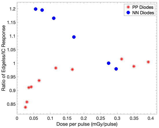
Figure 8.
The ratio of the responses of the central edgeless diode and IC is investigated with respect to DPP. The ratios are normalized to a DPP of 0.27 mGy/pulse, corresponding to SSD of 100 cm. The output of PP diodes was obtained using the edgeless array compared to the response of NN diodes.
The selection of the substrate doping, PP or NN, significantly influences the DPP dependence. The NN device exhibits a +20% increase in its response already at 0.08 mGy/pulse while, at the same dose rate, the PP diodes have a variation within 5%. Notably, for a DPP of 0.025 mGy/pulse, there is an approximate 15% reduction in the response of the edgeless array for PP diodes, which has little applicability in realistic clinical scenarios.
3.2.4. Angular Dependence
The normalized ratios for nine edgeless diodes to the TPS-predicted dose at 0° are presented in Figure 9. The selection of these diodes aims to emphasize the anticipated attenuation effects within the array structure with respect to the direction of the beam.
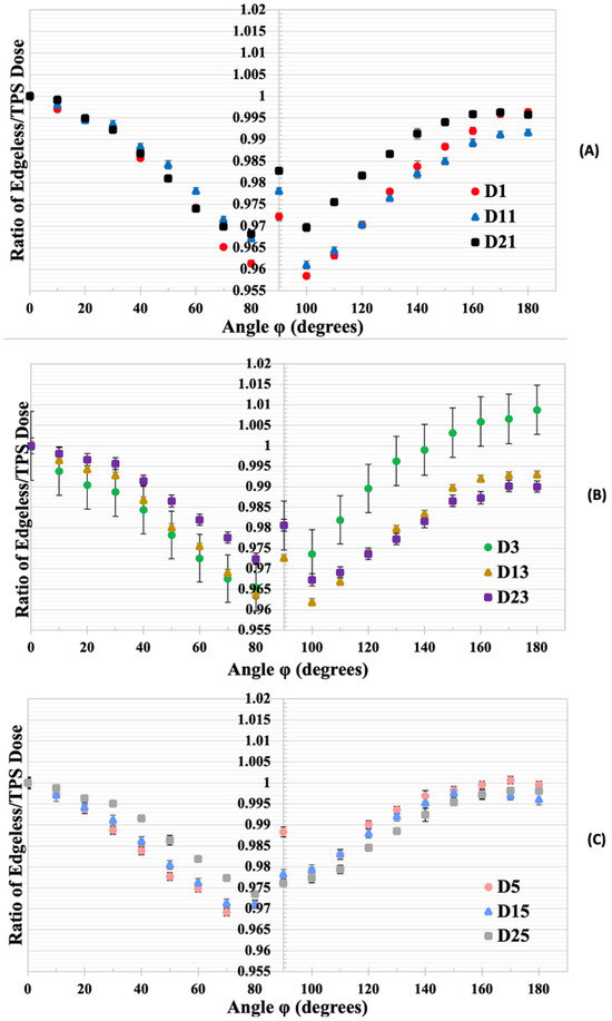
Figure 9.
(A) The normalized dose ratios for edgeless diodes D1, D11, and D21 to the TPS-predicted dose at 0°. (B) The normalized dose ratios for diodes D3, D13, and D23. (C) The normalized dose ratios for diodes D5, D15, and D25. Error bars represent the standard deviation based on three measurements with the edgeless array.
Diodes located at a greater depth (specifically, D1, D3, and D5) exhibit a more pronounced angular dependency when compared with diodes positioned closer to the surface in respect to the beam direction (diodes D21, D23, and D25). Diode D21 demonstrates a consistent response, varying by no more than 3% across all irradiation angles, while diode D1 experiences a reduction in normalized dose ratio, reaching 4% for angles close to lateral irradiation (90°). The measurements for irradiation at an angle of 0° and 180° exhibited discrepancies of less than 1% for all diodes.
The polar plots in Figure 10 illustrate the response of three diodes in comparison to the dose predicted by TPS at their respective positions, showcasing the normalized dose ratios with respect to the ratio obtained at a 0° irradiation angle.
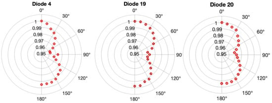
Figure 10.
The variation in angle sensitivity for three diodes within the edgeless array. Polar plots illustrate the ratio of edgeless dose to TPS dose, normalized to the value at 0°, for diode 4, diode 19, and diode 20. Error bars, derived from three measurements using the edgeless array, are contained within the symbols.
Diode 20 exhibits high symmetry around 90° with a smoothly changing response function. In contrast, diode 4 displays a larger reduction response from 0° to 90° compared to the range between 90° and 180°, accompanied by a discontinuous spike in the response at 90°. Most diodes, including D19 in Figure 10 and Figure 11, show a similar discontinuity, typically at or below 1%. Additionally, diode 19 demonstrates a slightly suppressed response between 90° and 180°. All three diodes indicate an under-response of less than 1% when comparing face-up irradiation (0°) to face-down irradiation (180°). Furthermore, asymmetries in the response around 90° are consistently less than 1% for all diodes.
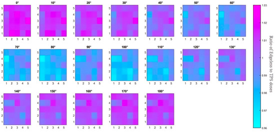
Figure 11.
An overview of the study on angular dependence. The 2D color map illustrates the ratio of dose from the edgeless diode to the simulated TPS dose for each angle. Diode 1 (D1) corresponds to the color square at the bottom left corner with coordinates (1, 1), while D25 at the top right has coordinates (5, 5). The displayed dose ratios in this representation are not normalized to the ratios at 0°.
In summary, although a maximum variation of 4% is observed with some pixels for angles between 80° and 120°, the angular dependence of all diodes remained within 2% for irradiation angles below 80° and above 120°. The array’s angular dependence is visually represented in Figure 11 through a color map. Notably, the diode to TPS dose ratios in this case are not normalized to 0° but simply calculated as the ratio of the dose recorded by the sensor (calculated using the calibration factor described in Section 3.1) and the dose simulated by the TPS in the detector location. As the irradiation angle increases, the effects of attenuation from each silicon pixel become more evident, with dose ratios decreasing from approximately 1.02 to 0.97. The color map also highlights an increase in the ratios at 90° due to the residual airgap between the sensor array and the surrounding plastic phantom (estimated to be 100 microns). The small airgap between the diode and its encapsulation allows for higher penetration of the photons, which is not taken into account by the TPS. Additionally, Table 1 provides a comparison of the angular dependence of the edgeless array with currently available commercial 2D arrays.

Table 1.
A comparison of the angular dependence of the edgeless array with directional responses measured in commercial 2D arrays. The methodology specifies whether the beam was coplanar (couch angle equals 0) or non-coplanar (couch angle not equal to zero), along with the measured angular range, beam energy, and field size utilized. Angular responses are presented as either the maximum deviation or upper/lower bounds within the angular range. For MapCHECK, values in brackets indicate results after corrections are applied.
4. Discussion
The edgeless array demonstrated excellent linearity in dose response across a dose range of 50 to 500 cGy at 6 MV, yielding R2 = 1. The average sensitivity throughout the array was 6.95 × 10⁻³ ± 2.3 × 10⁻⁵ Gy/nC, indicating a reproducibility of 0.33%. The reproducibility of the sensitivity between the two different LINACs and hospitals was measured to be 3.6%. The sensitivity recorded in this work is much smaller compared with that in previous works [31] using the same edgeless diode architecture but with a smaller sensitive area (0.5 × 0.5 mm2), which is reported to be approximately 15.29 ± 0.01 nC/Gy (6.5 × 10⁻² ± 4.78 × 10⁻⁵ Gy/nC). The edgeless array is also more sensitive to ionizing radiation compared to commercial grade devices such as SRS MapCHECK [45], being n-type diodes with a sensitivity of approximately 15 nC/Gy (6.67 × 10⁻² Gy/nC).
Percentage depth doses for a 10 × 10 cm2 field at 6 MV are closely matched with reference IC measurements within a 1.8% margin, spanning from dmax = 1.5 cm to a depth of 25 cm. This consistency is in line with earlier findings for PP edgeless diodes, which exhibited agreement with ionization chamber measurements within ±2% beyond the build-up region [31]. However, a slight systematic under-response is observed at greater depths in Figure 5. This discrepancy may be attributed to the uncorrected dose DPP dependence. As discussed in relation to Figure 8, the edgeless diode displays reduced relative sensitivity at lower DPP. Consequently, as the DPP gradually decreases at greater depths due to attenuation and the inverse square law, the PDD exhibits a large decrease compared to an IC, as the PDD is normalized to a reading at a higher DPP. This phenomenon is well-recognized for causing discrepancies in PDD curves on the order of a few percent [38].
The EPOM for the central diode was found to be 0.79 ± 0.05 mm downstream from the reference depth. The depth of the EPOM significantly relies on the construction of the detector and the measurement geometry. This result is in agreement with the estimation of the water equivalent thickness of the sensor physical overlayers composed of a protective polyimide (approx. 0.5 mm) and aluminum (approx. 0.1 mm) and the 0.1 mm thickness of the substrate. The aluminum used for the electrical connections possesses a density different from that of the solid water, contributing to the measured EPOM value. Additionally, it should be considered that the edgeless diode collects charge from the rear of the die as well, suggesting that the EPOM may be positioned at least halfway between the top ohmic contact and the rear pn-junction. In a previous investigation, the shift in the EPOM for the PTW 60012 diode was 0.6 ± 0.1 mm below its reference plane [46].
The output factor depicted in Figure 7 shows a close match with the CC04 IC, CC13 IC, and EBT3 readings. However, a slight under-response within smaller fields, not exceeding 2%, is present. which then gradually escalates to an over-response of 3% at a 20 × 20 cm2 field size. This good agreement is primarily attributed to the composition of packaging with low atomic number (Z) materials, such as Kapton, which minimizes the perturbation effects stemming from the packaging.
The over-response with larger fields is well known for silicon devices and can be related to the fact that silicon diode sensitivity increased with low-energy photons arising from Compton’s scattering, which increases with large fields [47,48]. Conversely, the under-response in smaller fields may be linked to the dose rate dependence. Discrepancies might also arise from the potential misalignment of the edgeless array central pixel. Airgaps also play a fundamental role in the output factor of extremely small field sizes, which are difficult to completely remove during the experimental setup. The construction of the array may also introduce parasitic airgaps due to the superposition of protection overlayers of Kapton. Studies employing Monte Carlo simulations on optically stimulated luminescent dosimeters indicate that the introduction of air gaps upstream to the sensitive volume leads to a reduction in dose compared to scenarios without air gaps. Even an air gap of a mere 0.5 mm can cause an under-response exceeding 5% [49]. This effect becomes prominent primarily for small fields measuring below 18 mm, where electrons scattered out of the sensitive volume due to the presence of air are not compensated for due to the absence of lateral charge particle equilibrium (LCPE).
The dose-rate dependence of the edgeless array for the DPP ranging from 0.03 mGy/pulse to 0.39 mGy/pulse is demonstrated in Figure 8. Normalizing the relative sensitivity of the edgeless array to an ionization chamber revealed a variation of ±2% of all the p-type edgeless diodes across the 0.12 to 0.39 mGy/pulse range, covering the dose rates typically used in SRS; however, lower dose rates will need to be corrected, since an underestimation of the dose up to 15% for the DPP was observed with dose rates lower than 0.1 mGy/pulse. Previous studies on different structures of p-type edgeless diodes have demonstrated similar results for DPP variation [28,31]. Notably, PP diodes exhibit a reduced and more consistent dependence on DPP compared to NN diodes. The established literature strongly favors pre-irradiated p-type diodes over n-type due to their flattened dose rates [50,51,52].
The dose rate dependence can be related to the correlation between the minority carrier lifetime and several other factors: irradiation history, resistivity, as well as the concentration and energy levels of recombination–generation (RG) centers within the band gap. According to the Shockley–Read–Hall theory, a super-linear response is anticipated at high dose rates of pulse LINAC beams, owing to the comparable excess concentration of minority charge carriers to the equilibrium majority concentration. This increased minority carrier lifetime at higher dose rates contributes to the observed super-linear response [50,52]. Equivalently, it can be reasoned that RG centers fill at a faster pace with larger DPPs, allowing a greater collection of electron–hole pairs without recombination. Conversely, lower DPPs result in a higher proportion of RG centers yet to be filled, thereby reducing the relative sensitivity [53].
Studies show that the DPP dependency observed with the Octavius 1000SRS (PTW Freiburg GmbH, Freiburg, Germany) decreases at a high dose rate [43,44]. A similar trend was observed with NN edgeless diodes and reported with the n-type EDGE diodes of the SRS MapCHECK [42]. These results from the literature, and this work, indicate that pre-irradiated lower-resistivity p-type substrates are the best option to achieve minimal DPP dependency.
The angular dependence of all 25 diodes in the edgeless array was conserved within 2% for angles smaller than 80° or larger than 120°; however, there is a measurable effect of attenuation of neighbor diodes. The most notable reduction in signal occurs at angles between 80° and 120°, displaying up to −4% variation comparing the edgeless-to-TPS dose ratio at 0°. The diodes exhibit less than 1% discrepancies to face-up and face-down irradiation, demonstrating the excellent performance of the 3D junction and negligible response variation due to attenuation by the substrate. This enables complete charge collection even when irradiation comes from the rear side, which may be unattainable with other planar semiconductor technologies.
Considering that single p-type edgeless diodes exhibited a consistent angular response within 4% across 180° of irradiation angles in the transverse plane [31], it is concluded that the array structure has not significantly altered the intrinsic angular independence of the diodes even though the measurements were compared to the TPS dose, which depends on its dose algorithm. This result is promising for the development of larger arrays or higher densities for improved spatial resolution.
To ensure precise absolute dosimetry during SRS treatment, QA correcting for the angular dependency of up to 4% is necessary. Yet, when compared with other 2D arrays, it is possible that correcting the edgeless array during QA might diminish its directional response for lateral irradiation, which has not yet been attained in commercial detectors. Additionally, the angular response of single edgeless diodes remains largely unaffected by the 2D 5 × 5 array structure, confirming the expected angular independence of the edgeless array compared to existing QA dosimeters.
5. Conclusions
The edgeless diode array displayed excellent linearity and exhibited sensitivities across the array with reproducibility of 0.33%. The 2D edgeless array’s measurements of PDDs closely match with the experimental output of the ion chambers for depths ranging from dmax to 20 cm, with a discrepancy of only 1.4%. A minor systematic under-response at increased depths was linked to a dependency on DPP. The 2D edgeless array’s output factor corresponds closely with the IC and EBT3 film responses, within 3.6% differences across field sizes from 0.5 to 20 cm. The DPP response only varied by ±2% within the 0.12 to 0.39 mGy/pulse range, indicating the nearly complete dose rate independence of the pre-irradiated silicon edgeless array. Notably, at dose rates below 0.1 mGy/pulse, a decrease of 15% was observed. The edgeless array dose angle dependence remains within 2% for most of the irradiated angles ranging from 0° to 180°; however, a maximum angular dependency of 4% (without post-processing or correction factors) was observed for angles close to 90°. While adjustments are necessary to meet the dose tolerances of SRS, these corrections could enable angular independence even for lateral irradiations, which is not currently achievable with commercial devices.
Overall, the edgeless array proved to be a promising choice for correction-free, angularly independent relative dosimetry under stereotactic radiosurgery conditions. To mitigate dose-per-pulse dependency, lower resistivity diodes could be employed with the minority carrier lifetime reduced with pre-irradiation.
Further studies are needed to validate the reliability of the array as a patient-specific quality assurance measurement tool for non-coplanar delivery systems such as the Gamma Knife® or CyberKnife®.
Supplementary Materials
The following supporting information can be downloaded at: https://www.mdpi.com/article/10.3390/app14135883/s1, S1: Data acquisition system; S2: The readout system; Figure S1: The GUI created for reading the edgeless array response; Figure S2: Dose Linearity Assessment for the central edgeless diode as measured on the Varian TrueBeam at SGHCC.
Author Contributions
Conceptualization, M.P., A.B. and A.B.R.; methodology, A.B., S.H., J.P. (Jessie Posar) and M.P.; software, A.B. and S.H.; formal analysis, A.B. and S.H.; investigation, A.B., S.H., J.P. (Jessie Posar) and M.P.; resources, J.M., Y.D. and J.P. (Joel Poder); writing—original draft preparation, A.B.; writing—review and editing, A.B., S.H., J.P. (Jessie Posar), M.P., J.M., Y.D., J.P. (Joel Poder), F.Z. and M.L.F.L.; visualization, A.B. and S.H.; supervision, M.P.; project administration, M.P. and M.L.F.L. All authors have read and agreed to the published version of the manuscript.
Funding
This research received no external funding.
Data Availability Statement
Data is contained within the article.
Acknowledgments
The authors would like to thank the St George Hospital Cancer Care Centre (SGHCC), and the Shoalhaven Cancer Care Centre (SCCC) staff for their valued time and assistance with measurements. A. Bashiri is sponsored by Najran University, Saudi Arabia.
Conflicts of Interest
The authors declare no conflicts of interest.
References
- Gruber, I.; Weidner, K.; Treutwein, M.; Koelbl, O. Stereotactic Radiosurgery of Brain Metastases: A Retrospective Study. Radiat. Oncol. 2023, 18, 202. [Google Scholar] [CrossRef] [PubMed]
- Vlachos, N.; Lampros, M.G.; Filis, P.; Voulgaris, S.; Alexiou, G.A. Stereotactic Radiosurgery versus Whole-Brain Radiotherapy after Resection of Solitary Brain Metastasis: A Systematic Review and Meta-Analysis. World Neurosurg. X 2023, 18, 100170. [Google Scholar] [CrossRef] [PubMed]
- Tuleasca, C.; Carey, G.; Barriol, R.; Touzet, G.; Dubus, F.; Luc, D.; Carriere, N.; Reyns, N. Impact of Biologically Effective Dose on Tremor Decrease after Stereotactic Radiosurgical Thalamotomy for Essential Tremor: A Retrospective Longitudinal Analysis. Neurosurg. Rev. 2024, 47, 73. [Google Scholar] [CrossRef] [PubMed]
- Kondziolka, D. Textbook of Stereotactic and Functional Neurosurgery; Springer: Berlin/Heidelberg, Germany, 2009. [Google Scholar]
- Larson, D.A.; Barani, I.J.; Roach, M., III; Sethi, R.A. Handbook of Evidence-Based Stereotactic Radiosurgery and Stereotactic Body Radiotherapy; Springer International Publishing: Cham, Switzerland, 2023. [Google Scholar]
- Raza, G.H.; Capone, L.; Tini, P.; Giraffa, M.; Gentile, P.; Minniti, G. Single-Isocenter Multiple-Target Stereotactic Radiosurgery for Multiple Brain Metastases: Dosimetric Evaluation of Two Automated Treatment Planning Systems. Radiat. Oncol. 2022, 17, 116. [Google Scholar] [CrossRef] [PubMed]
- Uto, M.; Torizuka, D.; Mizowaki, T. Single Isocenter Stereotactic Irradiation for Multiple Brain Metastases: Current Situation and Prospects. Jpn. J. Radiol. 2022, 40, 987–994. [Google Scholar] [CrossRef] [PubMed]
- Eder, M.M.; Reiner, M.; Heinz, C.; Garny, S.; Freislederer, P.; Landry, G.; Niyazi, M.; Belka, C.; Riboldi, M. Single-Isocenter Stereotactic Radiosurgery for Multiple Brain Metastases: Impact of Patient Misalignments on Target Coverage in Non-Coplanar Treatments. Z. Med. Phys. 2022, 32, 296–311. [Google Scholar] [CrossRef] [PubMed]
- Poder, J.; Brown, R.; Porter, H.; Gupta, R.; Ralston, A. Development of a Dedicated Phantom for Multi-Target Single-Isocentre Stereotactic Radiosurgery End to End Testing. J. Appl. Clin. Med. Phys. 2018, 19, 99–108. [Google Scholar] [CrossRef]
- Pudsey, L.M.M.; Biasi, G.; Ralston, A.; Rosenfeld, A.; Poder, J. Detection of Rotational Errors in Single-Isocenter Multiple-Target Radiosurgery: Is a Routine Off-Axis Winston–Lutz Test Necessary? J. Appl. Clin. Med. Phys. 2022, 23, e13665. [Google Scholar] [CrossRef]
- Simmons, G.; Gallitto, M.; Lee, A.; Baltuch, G.; Youngerman, B.E.; Wang, T.J.C. The Use of Stereotactic Radiosurgery to Treat Functional Disorders: A Topic Discussion. Am. Soc. Radiat. Oncol. 2023, 13, 395–399. [Google Scholar] [CrossRef]
- IAEA. Dosimetry of Small Static Fields Used in External Beam Radiotherapy: An IAEA-AAPM International Code of Practice for Reference and Relative Dose Determination (No. 483); Technical Report Series; IAEA: Vienna, Austria, 2017. [Google Scholar]
- Taylor, M.L.; Kron, T.; Franich, R.D. A Contemporary Review of Stereotactic Radiotherapy: Inherent Dosimetric Complexities and the Potential for Detriment. Acta Oncol. 2011, 50, 483–508. [Google Scholar] [CrossRef]
- Kairn, T.; Charles, P.; Crowe, S.B.; Trapp, J.V. Effects of Inaccurate Small Field Dose Measurements on Calculated Treatment Doses. Australas. Phys. Eng. Sci. Med. 2016, 39, 747–753. [Google Scholar] [CrossRef]
- International Commission on Radiation Units and Measurements. ICRU REPORT 91: Prescribing, Recording, and Reporting of Stereotactic Treatments with Small Photon Beams. J. ICRU 2014, 14, 1–160. [Google Scholar]
- Ade, N.; Nam, T.L. The Influence of Detector Size Relative to Field Size in Small-Field Photon-Beam Dosimetry Using Synthetic Diamond Crystals as Sensors. Radiat. Phys. Chem. 2015, 113, 6–13. [Google Scholar] [CrossRef]
- De Martin, E.; Alhujaili, S.; Fumagalli, M.L.; Ghielmetti, F.; Marchetti, M.; Gallo, P.; Aquino, D.; Padelli, F.; Davis, J.; Alnaghy, S.; et al. On the Evaluation of Edgeless Diode Detectors for Patient-Specific QA in High-Dose Stereotactic Radiosurgery. Phys. Medica 2021, 89, 20–28. [Google Scholar] [CrossRef] [PubMed]
- Tyler, M.; Liu, P.Z.Y.; Chan, K.W.; Ralston, A.; McKenzie, D.R.; Downes, S.; Suchowerska, N. Characterization of Small-Field Stereotactic Radiosurgery Beams with Modern Detectors. Phys. Med. Biol. 2013, 58, 7595–7608. [Google Scholar] [CrossRef] [PubMed]
- Blanck, O.; Masi, L.; Damme, M.C.; Hildebrandt, G.; Dunst, J.; Siebert, F.A.; Poppinga, D.; Poppe, B. Film-Based Delivery Quality Assurance for Robotic Radiosurgery: Commissioning and Validation. Phys. Medica 2015, 31, 476–483. [Google Scholar] [CrossRef] [PubMed]
- Devic, S.; Tomic, N.; Lewis, D. Reference Radiochromic Film Dosimetry: Review of Technical Aspects. Phys. Medica 2016, 32, 541–556. [Google Scholar] [CrossRef] [PubMed]
- Dieterich, S.; Cavedon, C.; Chuang, C.F.; Cohen, A.B.; Garrett, J.A.; Lee, C.L.; Lowenstein, J.R.; D’Souza, M.F.; Taylor, D.D.; Wu, X.; et al. Report of AAPM TG 135: Quality Assurance for Robotic Radiosurgery. Med. Phys. 2011, 38, 2914–2936. [Google Scholar] [CrossRef] [PubMed]
- Ahmed, S.; Zhang, G.; Moros, E.G.; Feygelman, V. Comprehensive Evaluation of the High-Resolution Diode Array for SRS Dosimetry. J. Appl. Clin. Med. Phys. 2019, 20, 13–23. [Google Scholar] [CrossRef]
- Decabooter, E.; Swinnen, A.C.; Öllers, M.C.; Göpfert, F.; Verhaegen, F. Operation and Calibration of the Novel PTW 1600SRS Detector for the Verification of Single Isocenter Stereotactic Radiosurgery Treatments of Multiple Small Brain Metastases. Br. J. Radiol. 2021, 94, 20210473. [Google Scholar] [CrossRef]
- Junis, I.; Yousif, Y.; Stensmyr, R.; Barber, J. Comprehensive Characterisation of the IBA MyQA SRS for SRS and SBRT Patient Specific Quality Assurance. Phys. Eng. Sci. Med. 2024, 47, 327–337. [Google Scholar] [CrossRef]
- Shi, J.; Simon, W.E.; Zhu, T.C. Modeling the Instantaneous Dose Rate Dependence of Radiation Diode Detectors. Med. Phys. 2003, 30, 2509–2519. [Google Scholar] [CrossRef]
- Benmakhlouf, H.; Andreo, P. Spectral Distribution of Particle Fluence in Small Field Detectors and Its Implication on Small Field Dosimetry. Med. Phys. 2017, 44, 713–724. [Google Scholar] [CrossRef]
- Andreo, P. The Physics of Small Megavoltage Photon Beam Dosimetry. Radiother. Oncol. 2018, 126, 205–213. [Google Scholar] [CrossRef] [PubMed]
- Alhujaili, S.F.; Biasi, G.; Alzorkany, F.; Grogan, G.; Al Kafi, M.A.; Lane, J.; Hug, B.; Aldosari, A.H.; Alshaikh, S.; Farzad, P.R.; et al. Quality Assurance of Cyberknife Robotic Stereotactic Radiosurgery Using an Angularly Independent Silicon Detector. J. Appl. Clin. Med. Phys. 2019, 20, 76–88. [Google Scholar] [CrossRef]
- Padelli, F.; Aquino, D.; Fariselli, L.; De Martin, E. IBA MyQA SRS Detector for CyberKnife Robotic Radiosurgery Quality Assurance. Appl. Sci. 2022, 12, 7791. [Google Scholar] [CrossRef]
- Alhujaili, S.F.; Davis, J.A.; Davies, J.; Lerch, M.L.F.; Rosenfeld, A.B.; Petasecca, M. Characterization of an “Edgeless” Dosimeter for Angular Independent Measurements in Advanced Radiotherapy Treatments. IEEE Trans. Radiat. Plasma Med. Sci. 2019, 3, 579–587. [Google Scholar] [CrossRef]
- Petasecca, M.; Alhujaili, S.; Aldosari, A.H.; Fuduli, I.; Newall, M.; Porumb, C.S.; Carolan, M.; Nitschke, K.; Lerch, M.L.F.; Kalliopuska, J.; et al. Angular Independent Silicon Detector for Dosimetry in External Beam Radiotherapy. Med. Phys. 2015, 42, 4708–4718. [Google Scholar] [CrossRef] [PubMed]
- Rozenfeld, A.B. Radiation Sensor and Dosimeter (MOSkin). Australian Patent. PCT/AU2008/000788. China Patent ZL 200880023328.8. US Patent N 8,742,357 B2, 3 June 2014. [Google Scholar]
- Fuduli, I.; Newall, M.K.; Espinoza, A.A.; Porumb, C.S.; Carolan, M.; Lerch, M.L.F.; Metcalfe, P.; Rosenfeld, A.B.; Petasecca, M. Multichannel Data Acquisition System Comparison for Quality Assurance in External Beam Radiation Therapy. Radiat. Meas. 2014, 71, 338–341. [Google Scholar] [CrossRef]
- Vicoroski, N.; Espinoza, A.; Duncan, M.; Oborn, B.M.; Carolan, M.; Metcalfe, P.; Menichelli, D.; Perevertaylo, V.L.; Lerch, M.L.F.; Rosenfeld, A.B.; et al. Development of a Silicon Diode Detector for Skin Dosimetry in Radiotherapy. Med. Phys. 2017, 44, 5402–5412. [Google Scholar] [CrossRef]
- Kawrakow, I. On the Effective Point of Measurement in Megavoltage Photon Beams. Med. Phys. 2006, 33, 1829–1839. [Google Scholar] [CrossRef] [PubMed]
- IAEA. Absorbed Dose Determination in External Beam Radiotherapy an International Code of Practice for Dosimetry Based on Standards of Absorbed Dose to Water; IAEA Safety Standards and Related Publications: Vienna, Austria, 2024. [Google Scholar]
- Rogers, D.W.O. Analytic and Graphical Methods for Assigning Errors to Parameters in Non-Linear Least Squares Fitting. Nucl. Instrum. Methods 1975, 127, 253–260. [Google Scholar] [CrossRef]
- Wilkins, D.; Li, X.A.; Cygler, J.; Gerig, L. The Effect of Dose Rate Dependence of P-Type Silicon Detectors on Linac Relative Dosimetry. Med. Phys. 1997, 24, 879–882. [Google Scholar] [CrossRef] [PubMed]
- Wong, J.H.D.; Knittel, T.; Downes, S.; Carolan, M.; Lerch, M.L.F.; Petasecca, M.; Perevertaylo, V.L.; Metcalfe, P.; Jackson, M.; Rosenfeld, A.B. The Use of a Silicon Strip Detector Dose Magnifying Glass in Stereotactic Radiotherapy QA and Dosimetry. Med. Phys. 2011, 38, 1226–1238. [Google Scholar] [CrossRef] [PubMed]
- Alhujaili, S. Development and Characterization of Solid-State Detectors for Medical Dosimetry in Intensity Modulated Radiation Therapy and Stereotactic Radiosurgery. Ph.D. Thesis, University of Wollongong, Wollongong, Australia, 2019. [Google Scholar]
- Petasecca, M.; Newall, M.K.; Booth, J.T.; Duncan, M.; Aldosari, A.H.; Fuduli, I.; Espinoza, A.A.; Porumb, C.S.; Guatelli, S.; Metcalfe, P.; et al. MagicPlate-512: A 2D Silicon Detector Array for Quality Assurance of Stereotactic Motion Adaptive Radiotherapy. Med. Phys. 2015, 42, 2992–3004. [Google Scholar] [CrossRef] [PubMed]
- Bai, L.; Xiao, Q.; Wang, Q.; Zhao, J.; Li, G.; Bai, S. Dosimetric Characteristics of a 2D Silicon Diode Array for Stereotactic Radiotherapy End-to-End Patient-Specific QA. Radiat. Phys. Chem. 2020, 173, 108885. [Google Scholar] [CrossRef]
- Markovic, M.; Stathakis, S.; Mavroidis, P.; Jurkovic, I.A.; Papanikolaou, N. Characterization of a Two-Dimensional Liquid-Filled Ion Chamber Detector Array Used for Verification of the Treatments in Radiotherapy. Med. Phys. 2014, 41, 51704. [Google Scholar] [CrossRef] [PubMed]
- Blanck, O.; Masi, L.; Chan, M.K.H.; Adamczyk, S.; Albrecht, C.; Damme, M.C.; Loutfi-Krauss, B.; Alraun, M.; Fehr, R.; Ramm, U.; et al. High Resolution Ion Chamber Array Delivery Quality Assurance for Robotic Radiosurgery: Commissioning and Validation. Phys. Medica 2016, 32, 838–846. [Google Scholar] [CrossRef] [PubMed]
- Rose, M.S.; Tirpak, L.; Van Casteren, K.; Zack, J.; Simon, T.; Schoenfeld, A.; Simon, W. Multi-Institution Validation of a New High Spatial Resolution Diode Array for SRS and SBRT Plan Pretreatment Quality Assurance. Med. Phys. 2020, 47, 3153–3164. [Google Scholar] [CrossRef]
- Looe, H.K.; Harder, D.; Poppe, B. Experimental Determination of the Effective Point of Measurement for Various Detectors Used in Photon and Electron Beam Dosimetry. Phys. Med. Biol. 2011, 56, 4267. [Google Scholar] [CrossRef]
- Weber, C.; Kranzer, R.; Weidner, J.; Kröninger, K.; Poppe, B.; Looe, H.K.; Poppinga, D. Small Field Output Correction Factors of the MicroSilicon Detector and a Deeper Understanding of Their Origin by Quantifying Perturbation Factors. Med. Phys. 2020, 47, 3165–3173. [Google Scholar] [CrossRef] [PubMed]
- Papaconstadopoulos, P.; Tessier, F.; Seuntjens, J. On the Correction, Perturbation and Modification of Small Field Detectors in Relative Dosimetry. Phys. Med. Biol. 2014, 59, 5937–5952. [Google Scholar] [CrossRef] [PubMed]
- Charles, P.H.; Crowe, S.B.; Kairn, T.; Kenny, J.; Lehmann, J.; Lye, J.; Dunn, L.; Hill, B.; Knight, R.T.; Langton, C.M.; et al. The Effect of Very Small Air Gaps on Small Field Dosimetry. Phys. Med. Biol. 2012, 57, 6947. [Google Scholar] [CrossRef] [PubMed][Green Version]
- Grusell, E.; Rikner, G. Radiation Damage Induced Dose Rate Non-Linearity in an n-Type Silicon Detector. Acta. Oncol. 1984, 23, 465–469. [Google Scholar] [CrossRef] [PubMed]
- Rikner, G.; Grusell, E. Effects of Radiation Damage on P-Type Silicon Detectors. Phys. Med. Biol. 1983, 28, 1261. [Google Scholar] [CrossRef]
- Saini, A.S.; Zhu, T.C. Dose Rate and SDD Dependence of Commercially Available Diode Detectors. Med. Phys. 2004, 31, 914–924. [Google Scholar] [CrossRef]
- Rosenfeld, A.B.; Biasi, G.; Petasecca, M.; Lerch, M.L.F.; Villani, G.; Feygelman, V. Semiconductor Dosimetry in Modern External-Beam Radiation Therapy. Phys. Med. Biol. 2020, 65, 16TR01. [Google Scholar] [CrossRef]
Disclaimer/Publisher’s Note: The statements, opinions and data contained in all publications are solely those of the individual author(s) and contributor(s) and not of MDPI and/or the editor(s). MDPI and/or the editor(s) disclaim responsibility for any injury to people or property resulting from any ideas, methods, instructions or products referred to in the content. |
© 2024 by the authors. Licensee MDPI, Basel, Switzerland. This article is an open access article distributed under the terms and conditions of the Creative Commons Attribution (CC BY) license (https://creativecommons.org/licenses/by/4.0/).