Article

Bond Properties of Glass-Fiber-Reinforced Polymer Hybrid Rebar in Reinforced Concrete with Respect to Bond Length

Department of Civil Engineering, Kangwon National University, 346 Jungang-ro, Samcheok-si 25913, Republic of Korea
*
Authors to whom correspondence should be addressed.
Appl. Sci. 2024, 14(11), 4576; https://doi.org/10.3390/app14114576
Submission received: 25 April 2024 / Revised: 20 May 2024 / Accepted: 23 May 2024 / Published: 27 May 2024
(This article belongs to the Special Issue High-Reliability Structures and Materials in Civil Engineering)

Abstract

:
Preventing rebar corrosion in reinforced concrete (RC) structures has been actively researched worldwide. One of the most powerful solutions is the use of fiber-reinforced polymer (FRP) rebars. However, there are limitations in the mechanical design and construction of FRP rebars because their tensile characteristics are extremely different from those of conventional rebars and they have a different modulus of elasticity. FRP rebars are relatively cost-efficient when fabricated with glass fibers, but they are still costly compared to conventional rebars. Therefore, hybrid rebars fabricated by covering conventional rebars with glass FRP (GFRP) materials were developed in this study. GFRP hybrid rebars have increased durability in marine environments while maintaining the same mechanical properties as conventional rebars. As the difference in rebar diameter of the bonded area decreased, the tensile strength of the concrete increased. As a result, pull-out failure or tensile failure caused by the yielding of the rebars occurred in small-diameter rebars. The experimental results showed that the maximum load for the D13 deformed steel bar was 52.2 kN at a bond length of 50 mm and 76.1 kN at 100 mm, while for the D19 deformed steel bar, it was 65.3 kN at 50 mm and 103.7 kN at 100 mm. The bond properties of hybrid GFRB rebars were found to be lower than those of deformed steel bars. These properties were improved greatly by increasing the thickness of the GFRP materials on the surface of the deformed steel bars, highlighting a path toward high-performance, corrosion-resistant concrete.

1. Introduction

Reinforced concrete (RC) has long been recognized as a construction material with excellent constructability, economic efficiency, fire resistance, and durability, but it naturally ages over time [1,2]. In addition, the performance and usability of the material slowly deteriorate due to changes in the surrounding environment [1,2,3,4].
The service life of RC is generally determined by the degradation of the mechanical function due to concrete damage and the corrosion of rebars [5,6]. While RC is particularly well suited for marine and harbor structures, the rebar in RC structures can be corroded due to the infiltration of the chlorides contained in seawater. Therefore, instead of conventional rebars, epoxy-coated steel bars have been used in RC structures exposed to such corrosive environments [7]. In addition, technologies to prevent the corrosion of rebars using fiber-reinforced polymer (FRP) composites have been developed and applied. Epoxy-coated steel bars allow easy structural design and construction because their mechanical behavior is the same as that of conventional rebar, but they are also susceptible to corrosion in bent sections of the bars [8,9]. The corrosion that occurs in these vulnerable sections reduces the durability and mechanical functions of RC structures [10]. FRP rebars, on the other hand, have excellent durability because they are free from corrosion [11,12]. However, there are limitations in the mechanical design and construction of FRP rebars because their tensile characteristics and elastic modulus are very different from those of conventional rebars. FRP rebars are relatively economical when fabricated with glass fibers, but they are still expensive compared to conventional rebars [13,14]. The bond characteristic of GFRP bars in concrete is the most critical parameter for using the material in corrosion-free concrete structures. Unlike steel reinforcement, GFRP materials have anisotropic, non-homogeneous, and linear elastic properties, resulting in different force transfer mechanisms between reinforcement and concrete [15].
In this study, hybrid rebars fabricated by covering conventional rebar with FRP materials are considered. FRP rebar can have increased durability under chloride-induced corrosion conditions, such as marine exposure, while maintaining the same mechanical properties as conventional rebars. Due to concerns about the degradation of the bonding properties with concrete materials, as in the case of epoxy-coated steel rebars, an experimental study on the bond properties of glass FRP (GFRP) hybrid rebars is reported.

2. Experimental Materials and Methods

2.1. Materials Used

2.1.1. GFRP Hybrid Rebars

GFRP hybrid rebars were fabricated using the pultrusion method, a method generally used for automatic mass production, as shown in Figure 1. The basic structure of a GFRP hybrid rebar is shown in Figure 2. A deformed steel bar is located in the center, and the outer surface is covered with GFRP material through braiding. This new type of rebar can significantly improve the modulus of elasticity for tensile and shear stresses compared to previous FRP rebars [1,2,9]. In addition, the external GFRP reinforcement can prevent the corrosion of the rebar in the center [1,2,9].
GFRP materials use E-glass fiber (SE1200-2200TEX; Owens Corning, Toledo, OH, USA), vinyl ester (VE), and unsaturated polyester (PE) as resins. VE and unsaturated PE are known to be effective porosity-forming resins. Table 1 shows the properties of the materials used.

2.1.2. Materials Used and Mix Proportions

Ordinary type 1 Portland cement (OPC) was used in this study. The physical and chemical properties of the OPC used are shown in Table 2 and Table 3 [16]. The physical properties of the coarse and fine aggregates used are shown in Table 4 [17] and Table 5 [18]. The maximum dimension of coarse aggregate was 25 mm.
To analyze the bond properties of GFRP hybrid rebars, concrete that exhibited 27 MPa at 28 days of age was used in this study. Table 6 shows the mix proportions.

2.2. Experimental Variables

Seven different rebar structures, including three conventional, one epoxy-coated steel, and three GFRP hybrid rebars, were tested to investigate the bond properties of GFRP hybrid rebars. Analysis of bond performance properties was performed using 50- and 100-mm bond lengths. For the GFRP hybrid rebar, two conventional rebars with diameters of 10 mm and 13 mm were used, and the final diameter of the 10 mm GFRP hybrid was 16 mm. For the 13 mm diameter, the final diameters were 15 mm and 16 mm. The experimental variables for analyzing the bond properties of the GFRP hybrid rebars are shown in Table 7.

2.3. Experimental Methods and Contents

Using the seven rebar structures, forms of size 150 × 150 × 150 (mm3) were fabricated in accordance with KS F 2441 [19] to compare and analyze the bond properties of the specimens of each variable, as shown in Figure 3. Lengths of 50 and 100 mm were considered as the bond lengths of the rebars. As for the unbonded sections excluding the 50- and 100-mm bond lengths, rubber hoses were inserted into the rebars, as shown in Figure 4. Loading was performed at a rate of 23 kN/min as suggested by KS F 2441 [19], and 3 linear variable differential transformers were installed to measure the displacement (slip) and strain by load step. The GFRP hybrid rebar specimens are shown in Figure 5.
In the case of the KS F 2441 experimental method [19], the load line must be accurately aligned with the rebar during experimental preparation for the pull-out of the rebar. The surface that is in contact with concrete must also be accurately placed perpendicular to the load line in the device to fix the concrete structure so that the applied pull-out force can induce uniform stress on the contact surface. Owing to errors in specimen fabrication and experimental setup, however, it is highly likely that eccentricity will be applied to the pull-out force acting on the concrete. In this case, errors that interfere with the experimental purpose of investigating bond properties may occur.
The preparation of the experimental setup and the fabrication of specimens were performed through careful planning to verify the bond properties of the GFRP hybrid rebars by minimizing these errors. During the preparation of each specimen, a camping material (rubber plate) was used between the experimental setup and the specimen to transfer uniform load and remove eccentricity. The specimens for bond properties and the jig used are depicted in Figure 5.

3. Results and Discussion

3.1. Experimental Results of Deformed Steel Bars

The experimental results of the D13 deformed steel bar test showed that the maximum load was 52.2 kN when the bond length was 50 mm and 76.1 kN when it was 100 mm. In addition, the average bond strength was found to be approximately 25.4 MPa when the bond length was 50 mm. When the 50 mm bond length was tested, all three specimens exhibited pull-out failure due to cracking in the rebar and bonded surface. In contrast, the two specimens with a bond length of 100 mm exhibited tensile failure, in which the rebar yielded first, instead of pull-out failure. The experimental results of the D13 deformed steel bar are shown in Table 8.
The experimental results of the D16 deformed steel bar tests show that the maximum load was 64.5 kN when the bond length was 50 mm and 95.0 kN when it was 100 mm. The average bond strengths were approximately 23.7 and 18.4 MPa when the bond lengths were 50 and 100 mm, respectively. Two specimens with a 50 mm bond length exhibited splitting failure of concrete, and one specimen showed pull-out failure. All three specimens with a 100 mm bond length exhibited concrete splitting failure, not pull-out failure. The experimental results of the D16 deformed steel bar test are shown in Table 9.
The experimental results of the D19 deformed steel bar tests showed that the maximum load was 65.3 kN when the bond length was 50 mm and 103.7 kN when it was 100 mm. In addition, the average bond strengths were approximately 25.0 and 15.8 MPa when the bond lengths were 50 and 100 mm, respectively. In the case of a 50 mm bond length, two specimens exhibited concrete splitting failure, while one specimen showed rebar pull-out failure and splitting failure simultaneously. Similarly, for the 100 mm bond length steel bars, two specimens exhibited splitting failure and one specimen showed both pull-out and splitting failure. The experimental results of the D19 deformed steel bar are shown in Table 10.

3.2. Experimental Results of the D13 Epoxy-Coated Steel Bar

The experimental results of the D13 epoxy-coated steel bar showed that the maximum load ranged from 51.4 to 53.1 kN when the bond length was 50 mm and from 72.3 to 67.9 kN when it was 100 mm. The average bond strengths were approximately 25.8 and 17.0 MPa when the bond lengths were 50 and 100 mm, respectively. All three specimens with a 50 mm bond length exhibited rebar pull-out failure. Two 100 mm bond length specimens showed pull-out failure, while one specimen exhibited splitting failure. The experimental results of the epoxy-coated steel bar are shown in Table 11.

3.3. Experimental Results of the GFRP Hybrid Rebars

The experimental results of the deformed D10/GFRP/D16/Braid rebar showed that the maximum load ranged from 33.9 to 44.5 kN when the bond length was 50 mm and from 70.0 to 63.2 kN when it was 100 mm. In addition, the average bond strengths were approximately 16.1 and 13.2 MPa when the bond lengths were 50 and 100 mm, respectively. All three 50 mm bond length specimens exhibited pull-out failure. Two 100 mm bond length specimens showed splitting failure, and one specimen exhibited pull-out failure. The experimental results of the deformed D10/GFRP/D16/Braid rebar are shown in Table 12.
The experimental results of the deformed D13/GFRP/D16/Braid rebar showed that the maximum load ranged from 42.7 to 25.1 kN when the bond length was 50 mm and from 69.5 to 50.8 kN when it was 100 mm. In addition, the average bond strengths were approximately 14.4 and 11.4 MPa when the bond lengths were 50 and 100 mm, respectively. In the case of a 50 mm bond length, two specimens exhibited splitting failure and one specimen showed pull-out failure. In the case of a 100 mm bond length, two specimens showed pull-out failure and one specimen exhibited splitting failure. The experimental results of the deformed D13/GFRP/D16/Braid rebar are shown in Table 13.
Results of the deformed D13/GFRP/D15/Braid rebar experiments show that the maximum load ranged from 33.4 to 18.7 kN when the bond length was 50 mm and from 57.4 to 39.9 kN when it was 100 mm. The average bond strengths were approximately 11.1 and 10.3 MPa when the bond lengths were 50 and 100 mm, respectively. All three 50 mm bond length specimens experienced pull-out failure. Two 100 mm bond length specimens showed pull-out failure and one specimen exhibited splitting failure. Table 14 shows the experimental results of the deformed D13/GFRP/D15/Braid rebar. Typical modes of failure are shown in Figure 6.

3.4. Analysis of the Bond Properties of Each Variable

When the bond length was 50 mm, the effect of the epoxy coating on bond strength was not significant for a rebar diameter of D13. In addition, the bond strength decreased slightly as the diameter increased. When the bond length was 100 mm, however, splitting failure occurred in every specimen with a deformed steel bar. In contrast, the epoxy-coated steel bar exhibited a bond strength of approximately 17.15 MPa through pull-out failure at D13. This indicates that the epoxy-coated steel bar has lower bond performance with concrete than with conventional deformed steel bars, which failed due to the rupture of the rebar, even though the bond length increased with the epoxy coating. In the case of D13, the epoxy coating interfered with the adhesion between the concrete and rebar at the bonding interface. Moreover, most of the bond strength was generated by the deformed pattern; the reduction in bond strength due to epoxy was not significant because the magnitude of the load that was actually applied was similar (70 kN).
In addition, the maximum load showed a tendency to increase with the diameter of the rebar. When the bond length was increased from 50 to 100 mm, the load of the D13 deformed steel bar increased by approximately 40%, but that of the D19 deformed steel bar increased by only approximately 25%. The epoxy-coated steel bar also exhibited a similar tendency. For a rebar diameter of D13, when the bond length was 50 mm, the deformed steel bar and the epoxy-coated steel bar exhibited pull-out failure. The deformed steel rebar ruptured when the bond length was increased to 100 mm, suggesting that there was sufficient bonding force on the concrete, while the epoxy-coated steel bar specimen showed splitting failure. This indicates that the deformed steel bar will secure sufficient bond strength as the bond length increases, but the epoxy-coated steel bar bonds insufficiently to the concrete.
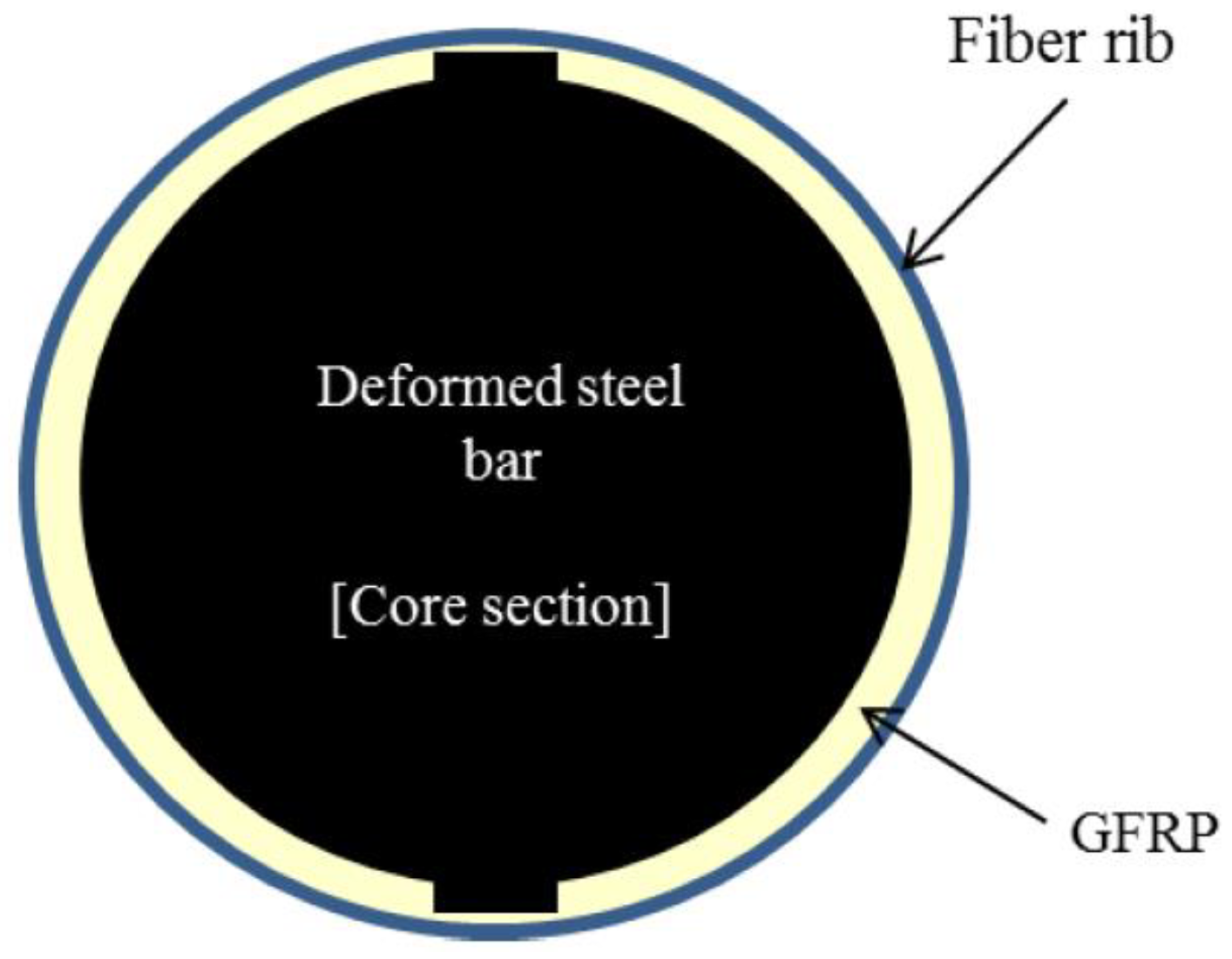
Considering the same rebar outer diameter, D16, the bond strength of the GFRP hybrid rebar decreased to a level causing great concern. The bond strength slightly decreased as the bond length increased, but remained very low compared to the deformed steel bar. When the diameter of the internal rebar decreased, e.g., in the case of the deformed D10/GFRP/D16/Braid rebar, the bond strength was slightly higher than the D13 internal rebar. This indicates that bond properties improve with increased GFRP thickness, which corresponds to the outer surface. This was also confirmed by comparing specimens with different GFRP thicknesses on the same D13 internal rebar.
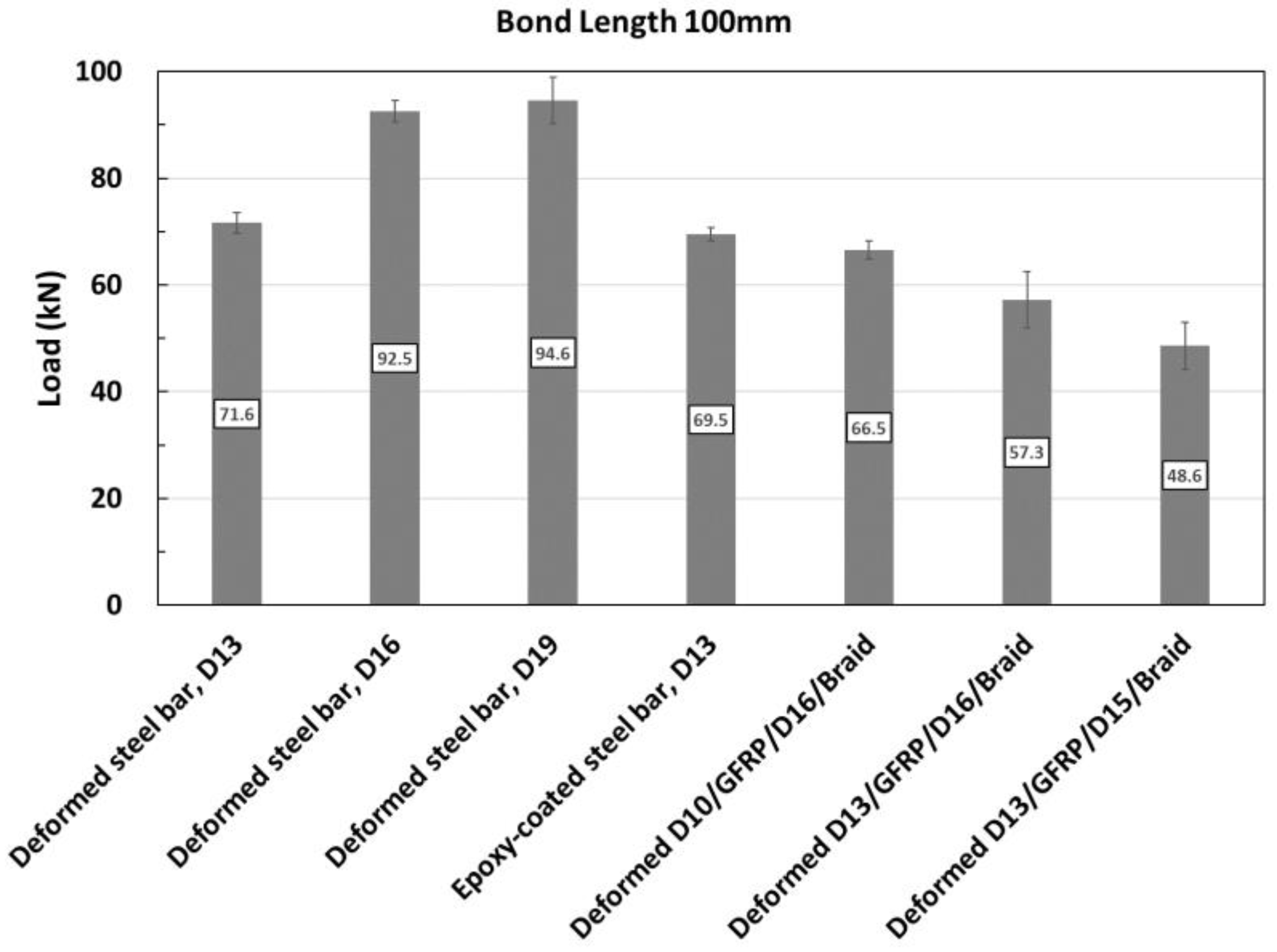
GFRP hybrid rebar bond testing results reveal that the shortcomings of the existing FRP rebars, such as degradation in modulus of elasticity, shear vulnerability, and brittle fracture, can be complemented because the main tension elements are rebars. In addition, the tensile performance can be improved by glass fibers on the surface. These current design standards can be easily applied. Due to the somewhat lower bond strength compared to conventional rebars, however, the mechanical properties, anchorage length, and connection characteristics required by the design standards require further study. The maximum loads of each variable based on bond length are shown in Figure 7 and Figure 8.
The epoxy-coated steel bar exhibited bond strengths similar to deformed steel bars with the same diameter. However, this result was obtained using a rebar diameter of D13, which is too small to be used in the field as flexural reinforcement. Therefore, it is necessary to compare and analyze cases with relatively larger rebar diameters.
In the case of the GFRP hybrid rebar with deformed steel bars inside, the bond properties were lower compared to deformed steel bars. The bond properties improved as the GFRP thickness on the outer surface of the rebar increased.

4. Conclusions

Pull-out experiments were performed to compare and analyze the bond properties of conventional deformed steel bars, epoxy-coated steel bars, and GFRP hybrid rebars in an effort to design RC structures capable of withstanding highly corrosive environments. The following conclusions were drawn:
(1)
Bond failure modes are generally determined by the radial stress distribution of the rebar. When the tensile strength of the matrix is smaller than the generated stress, splitting failure occurs. When it is larger, splitting failure or tensile failure caused by yielding of the rebar occurs.
(2)
The experiment on the bond performance of deformed steel bars revealed that there was no significant difference in bond strength based on the diameter of the deformed steel bar. Pull-out failure and tensile failure occurred in rebars with small diameters. In contrast, as the rebar diameter increased, the specimens exhibited splitting failure due to reduced structural tensile strength.
(3)
The bond properties of GFRP hybrid rebars with concrete were analyzed through experiments. The epoxy-coated steel bar exhibited bond strengths similar to a deformed steel bar with the same diameter. As this result was obtained using a rebar diameter of D13, which is too small to be used in the field as flexural reinforcement, future work is necessary to identify more accurate bond properties with concrete by comparing and analyzing cases with relatively larger rebar diameters.
(4)
The bond properties of GFRP hybrid rebars were lower compared to those of the deformed steel bars. However, the bond properties improved with increased GFRP thickness on the outer surface of the rebar.
(5)
Therefore, an external geometry that exhibits improved bond properties must be developed to apply these GFRP hybrid rebars to RC structures for high durability. Relative bond strength properties must also be further interrogated by calculating bond strengths based on the precise analysis of failure modes. These will be topics for further study by our group.

Author Contributions

Conceptualization, S.K., J.K. and C.P.; methodology, S.K., J.K. and C.P.; formal analysis, S.K., J.K. and C.P.; investigation, S.K., J.K. and C.P.; writing—original draft preparation, S.K., J.K. and C.P.; writing—review and editing, S.K., J.K. and C.P.; visualization, S.K., J.K. and C.P. All authors have read and agreed to the published version of the manuscript.

Funding

This work was supported by the Korea Institute of Energy Technology Evaluation and Planning (KETEP) and the Ministry of Trade, Industry & Energy (MOTIE) of the Republic of Korea (No. 20215810100020).

Institutional Review Board Statement

Not applicable.

Informed Consent Statement

Not applicable.

Data Availability Statement

The original contributions presented in the study are included in the article, further inquiries can be directed to the corresponding authors.

Conflicts of Interest

The authors declare no conflict of interest.

References

  1. KICT 2015-129-1; Structural Performance Improvement of Infrastructures Using FRP Composites. KICT: Goyang, Republic of Korea, 2015; pp. 1–4.
  2. Park, H. Evaluation of Bond Strength of Non-Corrosion of Hybrid FRP Rebars. Masters’ Thesis, Kangwon National University, Samcheok, Republic of Korea, 2015. [Google Scholar]
  3. Chung, L.; Kim, J.H.J.; Yi, S.T. Bond Strength Prediction for Reinforced Concrete Members with Highly Corroded Reinforcing Bars. Cem. Concr. Compos. 2018, 30, 603–611. [Google Scholar] [CrossRef]
  4. Soares, S.; Freitas, N.; Pereira, E.; Nepomuceno, E.; Pereira, E.; Sena-Cruz, H. Assessment of GFRP bond behaviour for the design of sustainable reinforced seawater concrete structures. Constr. Build. Mater. 2020, 231, 117277. [Google Scholar] [CrossRef]
  5. Kang, J.-E.; Kim, B.-I.; Park, J.-S.; Lee, J.-Y. Influence Evaluation of Fiber on the Bond Behavior of GFRP Bars Embedded in Fiber Reinforced Concrete. J. Korea Concr. Inst. 2012, 24, 79–86. [Google Scholar] [CrossRef]
  6. Moon, D.Y. A Study on the Basic Development Length of GFRP Rebar with Ribs. J. Korea Soc. Civ. Eng. 2012, 30, 485–493. [Google Scholar]
  7. Moon, D.-Y.; Oh, H. The Combined Effect of Concrete Environment and High Temperature on Interlaminar Shear Strength of FRP Reinforcement. J. Korea Concr. Inst. 2011, 23, 749–754. [Google Scholar] [CrossRef]
  8. Shi, Z.; Xie, N.; Fortune, K.; Gong, J. Durability of steel reinforced concrete in chloride environments: An overview. Constr. Build. Mater. 2012, 30, 125–138. [Google Scholar] [CrossRef]
  9. Park, C.; Park, Y.; Kim, S.; Ju, M. New emerging surface treatment of hybrid GFRP bar for strong durability of concrete structures. Smart Struct. Syst. 2016, 17, 593–610. [Google Scholar] [CrossRef]
  10. Islam, S.; Afefy, H.M.; Sennah, K.; Azimi, H. Bond characteristics of straight- and headed-end, ribbed-surface, GFRP bars embedded in high-strength concrete. Construct. Build. Mater. 2015, 83, 283–298. [Google Scholar] [CrossRef]
  11. Lau, D.; Pam, H.J. Experimental study of hybrid FRP-reinforced concrete beams. Eng. Struct. 2010, 32, 3857–3865. [Google Scholar] [CrossRef]
  12. Shi, J.; Sun, S.; Cao, X.; Wang, H. Pullout behaviors of basalt fiber-reinfroced polymer bars with mechanical anchorages for concrete structures exposed to seawater. Constr. Build. Mater. 2023, 373, 30866. [Google Scholar] [CrossRef]
  13. Mazaheripour, H.; Barros, J.A.; Sena-Cruz, J.M.; Pepe, M.; Martinelli, E. Experimental study on bond performance of GFRP bars in self-compacting steel fiber reinforced concrete. Compos. Struct. 2013, 95, 202–212. [Google Scholar] [CrossRef]
  14. Pecce, M.; Manfredi, G.; Realfonzo, R.; Cosenza, E. Experimental and analytical evaluation of bond properties of GFRP bars. J. Mater. Civ. Eng. 2001, 13, 282–290. [Google Scholar] [CrossRef]
  15. Yan, F.; Lin, Z.; Yang, M. Bond mechanism and bond strength of GFRP bars to concrete: A review. Compos. Part B Eng. 2016, 98, 56–69. [Google Scholar] [CrossRef]
  16. Jung, H.; Park, S.; Kim, S.; Park, C. Performance of SIFOCN based HPFRCC under Field Blast Load. Procedia Eng. 2017, 210, 401–408. [Google Scholar] [CrossRef]
  17. Kim, S.; Park, C. Durability and Mechanical Characteristics of Blast-Furnace Slag Based Activated Carbon-Capturing Concrete with respect to Cement Content. Appl. Sci. 2020, 10, 2083. [Google Scholar] [CrossRef]
  18. Kim, I.T.; Park, C.; Kim, S.; Cho, Y.-H. Evaluation of field applicability of pervious concrete materials for airport pavement cement treated drainage base course. Mater. Res. Innov. 2015, 19, 378–388. [Google Scholar] [CrossRef]
  19. KS F 2441; Standard Test Method for Comparing Concrete on the Basis the Bond Developed with Reinforcing Steel. Korean Standards Association: Seoul, Republic of Korea, 2010.
Figure 1. Fabrication of a GFRP hybrid rebar prototype using the pultrusion method.
Applsci 14 04576 g001
Figure 2. Structure of a GFRP hybrid rebar [9].
Applsci 14 04576 g002
Figure 3. Fabrication of GFRP hybrid rebar specimens for assessing bond properties. (a) Form fabrication; (b) Fabrication of specimens for assessing bond properties; (c) Concrete pouring.
Applsci 14 04576 g003
Figure 4. Fabrication of specimens for unbonded sections [2]. (a) Hose insertion for an unbonded section; (b) Specimen fabrication.
Applsci 14 04576 g004
Figure 5. GFRP hybrid rebar specimens and experiment setup [2]. (a) GFRP hybrid rebar specimens; (b) Experiment setup.
Applsci 14 04576 g005
Figure 6. Typical modes of failures observed experimentally.
Applsci 14 04576 g006
Figure 7. Maximum load of each variable for a 50 mm bond length.
Applsci 14 04576 g007
Figure 8. Maximum load of each variable for a 100 mm bond length.
Applsci 14 04576 g008
Table 1. Material properties.
MaterialTensile Strength (MPa)Elastic Modulus (GPa)
Deformed steel rebar400200
E-glass fiber241079
Vinyl ester resin93.7
Unsaturated polyester resin623.1
GFRP rebar1307.661.3
Table 2. Physical properties of OPC [16].
Specific GravityFineness (cm2/g)Stability (%)Setting Time (min.)Compressive Strength (MPa)
Initial SetFinal Set3 Days7 Days28 Days
3.1534000.1230410233140
Table 3. Chemical compositions of OPC [17].
SiO2Fe2O3CaOMgOSO3Al2O3Ig-loss
21.952.8160.123.322.116.592.58
Table 4. Physical properties of fine aggregate [17].
Specific GravityWater Absorption (%)Fineness Modulus
2.521.452.62
Table 5. Physical properties of coarse aggregate [18].
Dmax (mm)Specific GravityWater Absorption (%)Fineness Modulus
252.760.456.72
Table 6. Mix proportions.
Dmax (mm)W/CS/a (%)Mass per Unit Volume (kg/m3)
WCF.A.C.A.
250.4246.5171406817942
Table 7. Experimental variables for the bond properties of FRP hybrid rebars.
PrototypePrototype NameBond Lenth (mm)Quantity (ea)
Conventional rebarsDeformed steel bar, D13503
1003
Deformed steel bar, D16503
1003
Deformed steel bar, D19503
1003
Epoxy-coated steel rebarEpoxy-coated steel bar, D13503
1003
GFRP hybrid rebarDeformed D10/GFRP/D16/Braid503
1003
Deformed D13/GFRP/D15/Braid503
1003
Deformed D13/GFRP/D16/Braid503
1003
Total42
Table 8. Experimental results of the D13 deformed steel bar.
Bond Length (mm)Specimen 1Specimen 2Specimen 3
Max. Load (kN)Bond Strength (MPa)Failure ModeMax. Load (kN)Bond Strength (MPa)Failure ModeMax. Load (kN)Bond Strength (MPa)Failure Mode
5052.225.5Pull-out failure51.725.3Pull-out failure51.625.3Pull-out failure
100---69.517.0Yielding69.317.0Yielding
Table 9. Experimental results of the D16 deformed steel bar.
Bond Length (mm)Specimen 1Specimen 2Specimen 3
Max. Load (kN)Bond Strength (MPa)Failure ModeMax. Load (kN)Bond Strength (MPa)Failure ModeMax. Load (kN)Bond Strength (MPa)Failure Mode
5064.525.6Splitting failure53.521.3Pull-out failure60.524.1Splitting failure
10087.917.5Splitting failure97.418.8Splitting failure95.018.9Splitting failure
Table 10. Experimental results of the D19 deformed steel bar.
Bond Length (mm)Specimen 1Specimen 2Specimen 3
Max. Load (kN)Bond Strength (MPa)Failure ModeMax. Load (kN)Bond Strength (MPa)Failure ModeMax. Load (kN)Bond Strength (MPa)Failure Mode
5074.324.9Splitting and pull-out failure84.128.2Splitting failure65.321.9Splitting failure
10086.014.4Splitting failure94.115.8Splitting failure103.717.4Splitting and pull-out failure
Table 11. Experimental results of the epoxy-coated steel bar.
Bond Length (mm)Specimen 1Specimen 2Specimen 3
Max. Load (kN)Bond Strength (MPa)Failure ModeMax. Load (kN)Bond Strength (MPa)Failure ModeMax. Load (kN)Bond Strength (MPa)Failure Mode
50---53.126.0Pull-out failure51.425.2Pull-out failure
10068.416.7Splitting failure67.916.6Pull-out failure72.317.7Pull-out failure
Table 12. Experimental results of the deformed D10/GFRP/D16/Braid rebar.
Bond Length (mm)Specimen 1Specimen 2Specimen 3
Max. Load (kN)Bond Strength (MPa)Failure ModeMax. Load (kN)Bond Strength (MPa)Failure ModeMax. Load (kN)Bond Strength (MPa)Failure Mode
5033.913.5Pull-out failure44.517.7Pull-out failure43.217.2Pull-out failure
10066.513.2Pull-out failure63.212.6Pull-out failure70.013.9Splitting failure
Table 13. Experimental results of the deformed D13/GFRP/D16/Braid rebar.
Bond Length (mm)Specimen 1Specimen 2Specimen 3
Max. Load (kN)Bond Strength (MPa)Failure ModeMax. Load (kN)Bond Strength (MPa)Failure ModeMax. Load (kN)Bond Strength (MPa)Failure Mode
5025.110.0Pull-out failure42.717.0Splitting failure41.116.3Splitting failure
10051.510.3Pull-out failure69.513.8Splitting failure50.810.1Pull-out failure
Table 14. Experimental results of the deformed D13/GFRP/D15/Braid rebar.
Bond Length (mm)Specimen 1Specimen 2Specimen 3
Max. Load (kN)Bond Strength (MPa)Failure ModeMax. Load (kN)Bond Strength (MPa)Failure ModeMax. Load (kN)Bond Strength (MPa)Failure Mode
5026.211.1Pull-out failure18.77.9Pull-out failure33.414.2Pull-out failure
10057.412.2Splitting failure48.210.3Pull-out failure39.98.5Pull-out failure
Disclaimer/Publisher’s Note: The statements, opinions and data contained in all publications are solely those of the individual author(s) and contributor(s) and not of MDPI and/or the editor(s). MDPI and/or the editor(s) disclaim responsibility for any injury to people or property resulting from any ideas, methods, instructions or products referred to in the content.

