Computational Fluid Dynamics Investigation of Hydrodynamic Forces and Moments Acting on Stern Rudder Plane Configurations of a Submarine


Abstract
1. Introduction
2. Methodology
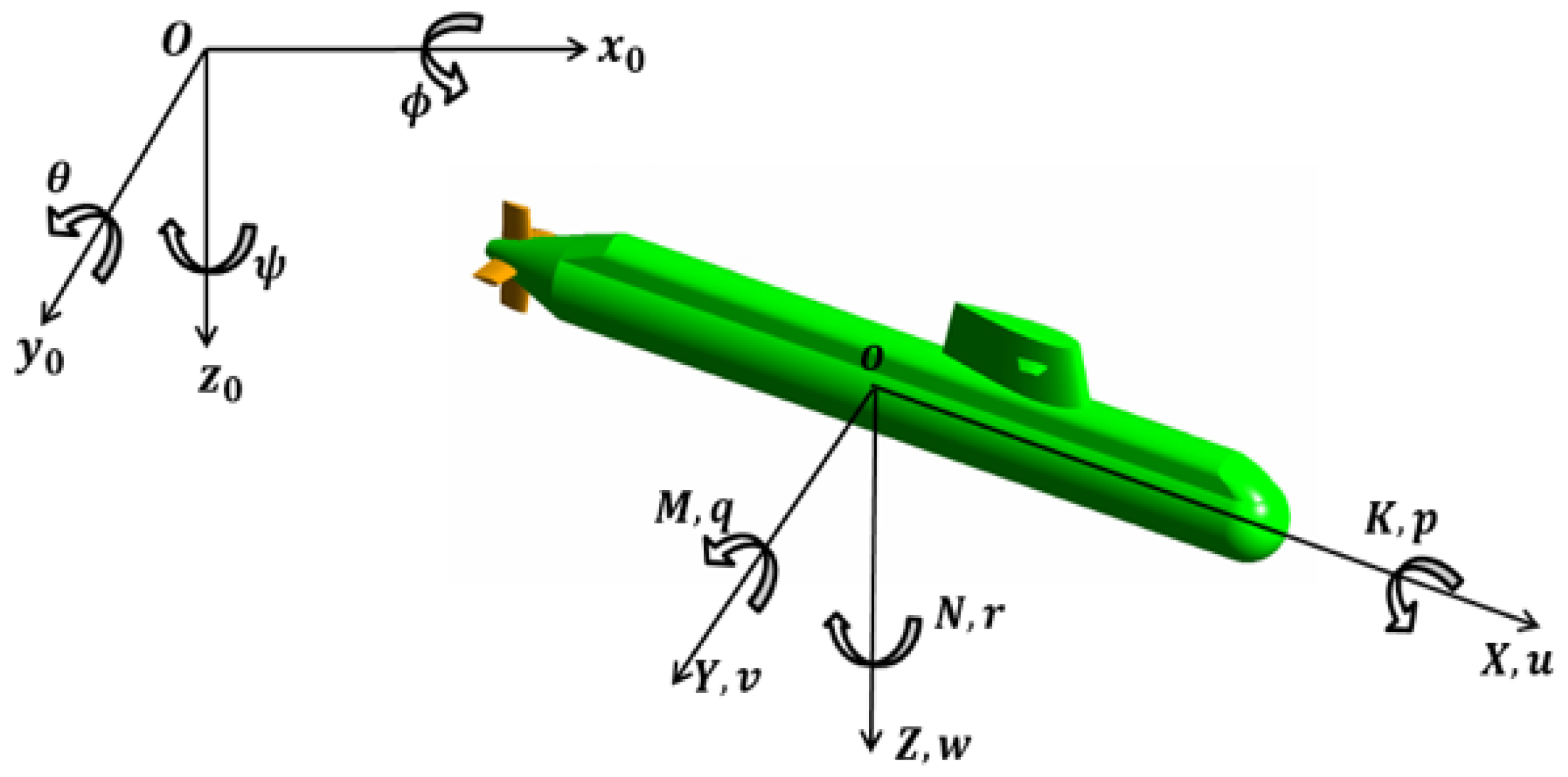
2.1. Coordinate Systems and Symbols
2.2. Equation of Motion of the Submarine
2.3. Simulation Method
3. Numerical Modeling
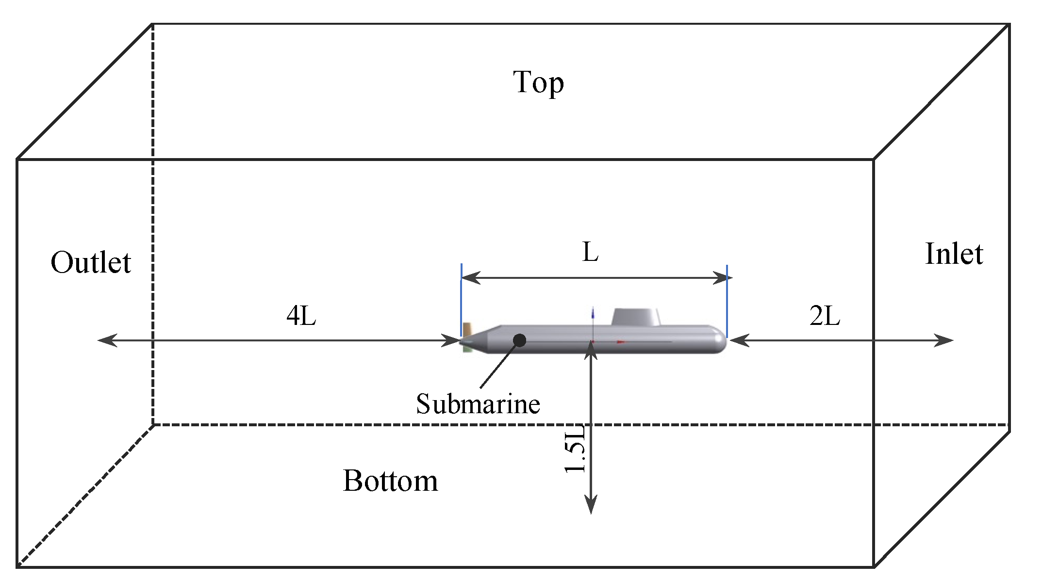
3.1. Case Study
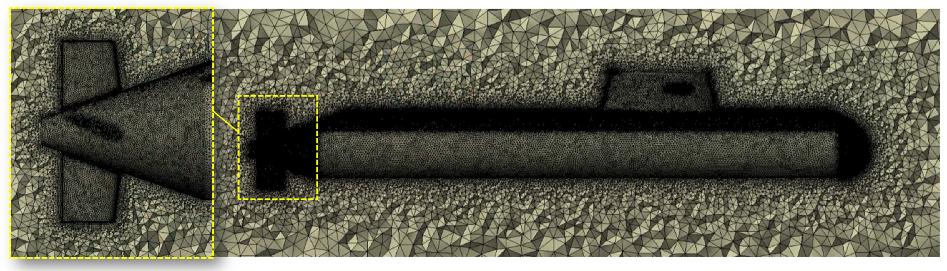
3.2. CFD-Based Modeling
4. Results
5. Conclusions
Author Contributions
Funding
Institutional Review Board Statement
Informed Consent Statement
Data Availability Statement
Conflicts of Interest
References
- Park, J.Y.; Kim, N.; Shin, Y.K. Experimental study on hydrodynamic coefficients for high-incidence-angle maneuver of a submarine. Int. J. Nav. Archit. Ocean Eng. 2016, 9, 100–113. [Google Scholar] [CrossRef]
- Ke, L.; Ye, J.; Liang, Q. Experimental Study on the Flow Field, Force, and Moment Measurements of Submarines with Different Stern Control Surfaces. J. Mar. Sci. Eng. 2023, 11, 2091. [Google Scholar] [CrossRef]
- Kim, H.; Hong, S.K. Numerical study on the hydrodynamic control derivatives of a high-speed underwater vehicle with X-stern configuration. J. Mech. Sci. Technol. 2012, 25, 3075–3082. [Google Scholar] [CrossRef]
- Fureby, C.; Anderson, B.; Clarke, D.; Erm, L.; Henbest, S.; Giacobello, M.; Jones, D.; Nguyen, M.; Johansson, M.; Jones, M.; et al. Experimental and numerical study of a generic conventional submarine at 10° yaw. Ocean Eng. 2016, 116, 1–20. [Google Scholar] [CrossRef]
- Khan, M.K.; Korulla, M.; Nagarajan, V.; Sha, O.P. Steady velocity measurements in the stern wake of submarine hull form at high angles of incidence. Ocean Eng. 2023, 277, 114281. [Google Scholar] [CrossRef]
- Nguyen, T.T.; Yoon, H.K.; Park, Y.; Park, C. Estimation of hydrodynamic derivatives of full-scale submarine using RANS solver. J. Ocean Eng. Technol. 2018, 20, 386–392. [Google Scholar] [CrossRef]
- Cho, Y.J.; Seok, W.; Cheon, H.H.; Rhee, S.H. Maneuvering simulation of an X-plane submarine using computation fluid dynamics. Int. J. Nav. Archit. Ocean Eng. 2020, 12, 843–855. [Google Scholar] [CrossRef]
- Wu, S.J.; Lin, C.C.; Liu, T.L.; Su, I.H. Robust design on the arrangement of a sail and control planes for improvement of underwater vehicle’s maneuverability. Int. J. Nav. Archit. Ocean Eng. 2020, 12, 617–635. [Google Scholar] [CrossRef]
- Jeon, M.J.; Yoon, H.K.; Hwang, J.; Cho, H.J. Analysis of the dynamic characteristics for the change of design parameters of an underwater vehicle using sensitivity analysis. Int. J. Nav. Archit. Ocean Eng. 2018, 10, 508–519. [Google Scholar] [CrossRef]
- Kim, H.; Ranmuthugala, D.; Leong, Z.Q.; Chin, C. Six-DOF simulation of an underwater vehicle undergoing straight line and steady turning maneuvers. Ocean Eng. 2018, 150, 102–112. [Google Scholar] [CrossRef]
- Zhang, Y.; Li, Y.; Sun, Y.; Zeng, J.; Wan, L. Design and simulation of X-rudder AUV’s motion control. Ocean Eng. 2017, 137, 204–214. [Google Scholar] [CrossRef]
- Zhang, Y.; Li, Y.; Zhang, G.; Zeng, J.; Wan, L. Design of X-rudder autonomous underwater vehicle’s quadruple-rudder allocation with Le’vy flight character. Int. J. Adv. Robot. Syst. 2017, 14, 1–15. [Google Scholar] [CrossRef]
- Broglia, R.; Cannarozzo, M.; Dubbioso, G.; Zaghi, S. Free Running Prediction of a Fully Appended Submarine: Effects of Stern Plane Configurations. In Proceedings of the VI International Conference on Computational Methods in Marine Engineering, Rome, Italy, 15–17 June 2015. [Google Scholar]
- Piaggio, B.; Vernengo, G.; Ferrando, M.; Mazzarello, G.; Viviani, M. Submarine Manoeuvrability Design: Traditional Cross-Plane vs. x-Plane Configurations in Intact and Degraded Conditions. J. Mar. Sci. Eng. 2022, 10, 2014. [Google Scholar]
- Park, J.H.; Shin, M.S.; Jeon, Y.H.; Kim, Y.G. Simulation-Based Prediction of Steady Turning Ability of a Symmetrical Underwater Vehicle Considering Interactions Between Yaw Rate and Drift/Rudder Angle. J. Ocean Eng. Technol. 2021, 35, 99–112. [Google Scholar] [CrossRef]
- Pan, Y.; Zhang, H.; Zhou, Q. Numerical simulation of unsteady propeller force for a submarine in straight ahead sailing and steady diving maneuver. Int. J. Nav. Archit. Ocean Eng. 2019, 11, 899–913. [Google Scholar] [CrossRef]
- Han, K.; Cheng, X.; Liu, Z.; Huang, C.; Chang, H.; Yao, J.; Tan, K. Six-DOF CFD Simulations of Underwater Vehicle Operating Underwater Turning Maneuvers. J. Mar. Sci. Eng. 2021, 9, 1451. [Google Scholar] [CrossRef]
- Guo, H.; Li, G.; Du, L. Investigation on the flow around a submarine under the rudder deflection condition by using URANS and DDES methods. Appl. Ocean Res. 2023, 131, 103448. [Google Scholar] [CrossRef]
- Vali, A.; Saranjam, B.; Kamali, R. Experimental and Numerical Study of a Submarine and Propeller Behaviors in Submergence and Surface Conditions. J. Appl. Fluid Mech. 2018, 11, 1297–1308. [Google Scholar] [CrossRef]
- Fossen, T.I. Guidance and Control of Ocean Vehicles, 3rd ed.; John Wiley and Son: Baffins Lane, UK, 1999; pp. 168–180. [Google Scholar]
- Menter, F. Two-Equation Eddy-Viscosity Turbulence Models for Engineering Applications. AIAA 1994, 32, 1598–1605. [Google Scholar] [CrossRef]
- Wilcox, C.D. Turbulence Modeling for CFD, 3rd ed.; DCW Industries Inc.: La Cafiada, CA, USA, 2006. [Google Scholar]
- Ansys Inc. Ansys Fluent Theory Guide 12.0; Ansys Inc.: Canonsburg, PA, USA, 2012; pp. 64–65. [Google Scholar]
- ITTC. Practical Guidelines for Ship CFD Application. In Proceedings of the 26th International Towing Tanks Conference, Rio de Janeiro, Brazil, 28 August–3 September 2011; Number 7.5-03-02-03; ITTC: Beijing, China, 2011; Available online: https://ittc.info/media/1357/75-03-02-03.pdf (accessed on 1 April 2024).
- Oh, K.J.; Kang, S.H. Full scale Reynold number effects for the viscous flow around the ship stern. Comput. Mech. 1992, 9, 85–94. [Google Scholar] [CrossRef]


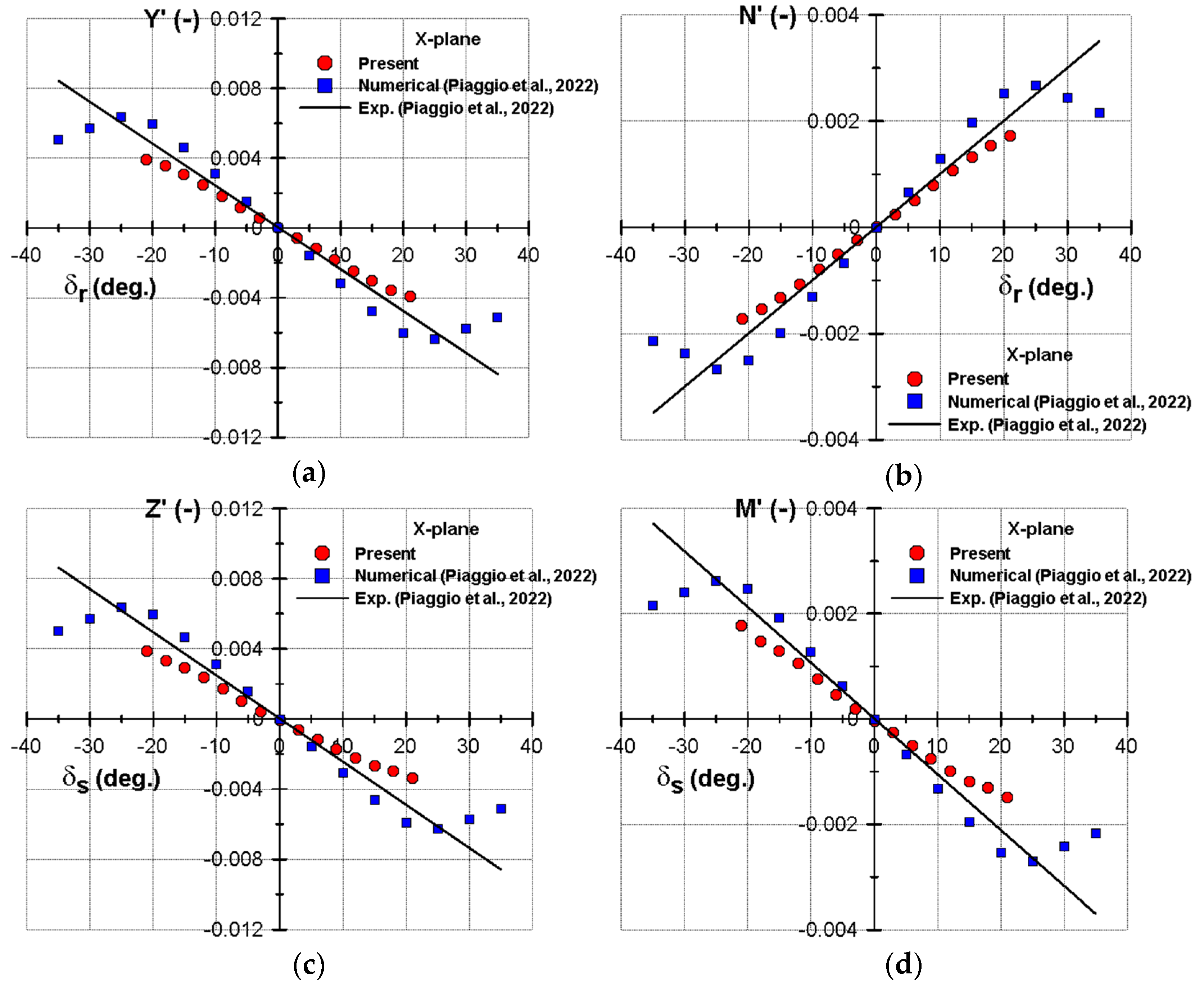
| Symbol | Current Study | Experiment (Piaggio et al. [14]) | Difference (%) |
|---|---|---|---|
| 1.17 × 10⁻² | 1.38 × 10⁻² | 15.22 | |
| 1.12 × 10⁻² | 1.41 × 10⁻² | 20.57 | |
| 4.84 × 10⁻³ | 6.10 × 10⁻³ | 20.66 | |
| −5.05 × 10⁻³ | −5.70 × 10⁻³ | 11.4 |
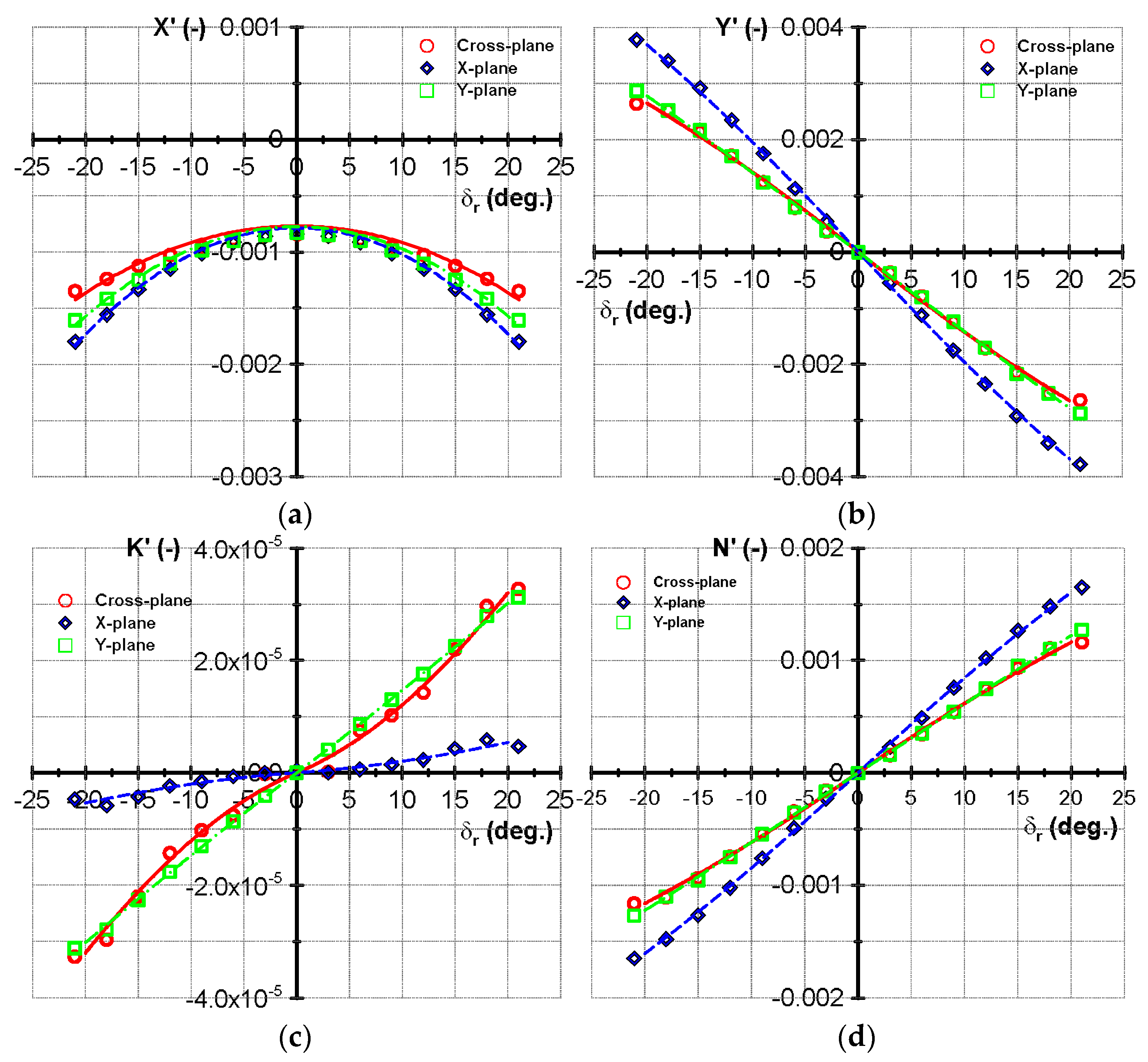
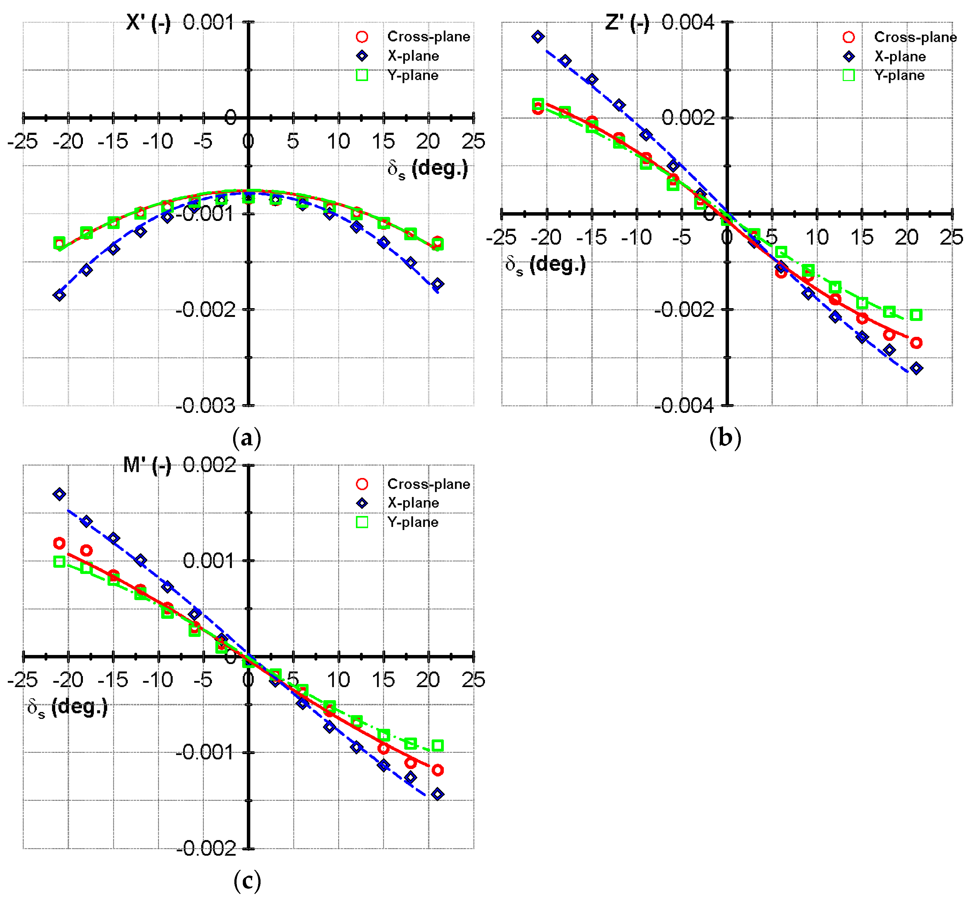
| Symbol | Cross-Rudder Plane | X-Rudder Plane | Y-Rudder Plane |
|---|---|---|---|
| −5.27 × 10⁻³ | −8.81 × 10⁻³ | −9.06 × 10⁻³ | |
| −4.91 × 10⁻³ | −9.66 × 10⁻³ | −7.40 × 10⁻³ | |
| 8.62 × 10⁻³ | 1.17 × 10⁻² | 8.07 × 10⁻³ | |
| −2.57 × 10⁻³ | −2.74 × 10⁻³ | −1.60 × 10⁻⁴ | |
| 9.48 × 10⁻³ | 1.12 × 10⁻² | 7.95 × 10⁻³ | |
| −6.97 × 10⁻³ | −4.28 × 10⁻³ | −4.47 × 10⁻³ | |
| −4.48 × 10⁻⁵ | −7.61 × 10⁻⁶ | −8.11 × 10⁻⁵ | |
| −1.43 × 10⁻⁴ | −2.38 × 10⁻⁵ | −2.11 × 10⁻⁵ | |
| 3.76 × 10⁻³ | 4.84 × 10⁻³ | 3.54 × 10⁻³ | |
| −1.54 × 10⁻³ | −1.35 × 10⁻³ | −2.11 × 10⁻³ | |
| −3.73 × 10⁻³ | −5.05 × 10⁻³ | −3.52 × 10⁻³ | |
| 9.67 × 10⁻⁴ | 1.03 × 10⁻³ | −1.71 × 10⁻⁴ |
Disclaimer/Publisher’s Note: The statements, opinions and data contained in all publications are solely those of the individual author(s) and contributor(s) and not of MDPI and/or the editor(s). MDPI and/or the editor(s) disclaim responsibility for any injury to people or property resulting from any ideas, methods, instructions or products referred to in the content. |
© 2024 by the authors. Licensee MDPI, Basel, Switzerland. This article is an open access article distributed under the terms and conditions of the Creative Commons Attribution (CC BY) license (https://creativecommons.org/licenses/by/4.0/).
Share and Cite
Phan, T.L.; Mai, T.L.; Nguyen, T.T. Computational Fluid Dynamics Investigation of Hydrodynamic Forces and Moments Acting on Stern Rudder Plane Configurations of a Submarine. Appl. Sci. 2024, 14, 4292. https://doi.org/10.3390/app14104292
Phan TL, Mai TL, Nguyen TT. Computational Fluid Dynamics Investigation of Hydrodynamic Forces and Moments Acting on Stern Rudder Plane Configurations of a Submarine. Applied Sciences. 2024; 14(10):4292. https://doi.org/10.3390/app14104292
Chicago/Turabian StylePhan, Thanh Long, Thi Loan Mai, and Tien Thua Nguyen. 2024. "Computational Fluid Dynamics Investigation of Hydrodynamic Forces and Moments Acting on Stern Rudder Plane Configurations of a Submarine" Applied Sciences 14, no. 10: 4292. https://doi.org/10.3390/app14104292
APA StylePhan, T. L., Mai, T. L., & Nguyen, T. T. (2024). Computational Fluid Dynamics Investigation of Hydrodynamic Forces and Moments Acting on Stern Rudder Plane Configurations of a Submarine. Applied Sciences, 14(10), 4292. https://doi.org/10.3390/app14104292