Article

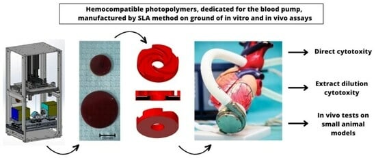
In Vitro and In Vivo Testing of Stereolithography (SLA)-Manufactured Haemocompatible Photopolymers for Blood Pump

1
Institute of Metallurgy and Materials Science, Polish Academy of Sciences, 25 Reymonta St., 30-059 Cracow, Poland
2
Foundation of Cardiac Surgery Development, Institute of Heart Prostheses, 345A Wolności St., 41-800 Zabrze, Poland
3
Faculty of Biomedical Engineering, Silesian University of Technology, Roosevelt St. 40, 41-800 Zabrze, Poland
4
Department of Internal Medicine, Jagiellonian University Medical College, 8 Skawińska St., 31-066 Cracow, Poland
5
Lithoz GmbH, Mollardgasse 85a/2/64-69, 1060 Vienna, Austria
6
Department of Histology, Faculty of Medicine, Jagiellonian University Medical College, 7 Kopernika St., 31-034 Cracow, Poland
7
AGH University of Krakow, 30 Mickiewicza St., 30-059 Cracow, Poland
8
Institute for Sensors, Photonics and Manufacturing Technologies, Laser and Plasma Processing, Joanneum Research Forschungsgesellschaft m.b.H., Leobner Straße 94a, 8712 Niklasdorf, Austria
*
Author to whom correspondence should be addressed.
Appl. Sci. 2024, 14(1), 383; https://doi.org/10.3390/app14010383
Submission received: 21 November 2023 / Revised: 28 December 2023 / Accepted: 28 December 2023 / Published: 31 December 2023
(This article belongs to the Special Issue Advances in Mechanics of Biomaterials)

Abstract

:
A major medical problem of state-of-the-art heart ventricular assist devices (LVADs) is device-induced thrombus formation due to inadequate blood-flow dynamics generated by the blood pump rotor. The latter is a highly complex device, with difficulties during conventional manufacturing through milling or casting. Therefore, the additive manufacturing technology relying on stereo-lithography (SLA) capable of producing parts of significantly increased freedom for a blood-flow-compatible, thrombus-risk-free design was chosen as novel and flexible technology for that type of application. However, as yet state-of-the-art SLA is not suitable to produce fully safe blood-contacting devices. Therefore, the present experiment covered chemical, mechanical, rheological, tribological, and complex biocompatibility characterization in accordance with i.a. ISO 10993 standards, including hemolysis and an acute thrombogenicity blood test on fresh animal blood (both as innovative laboratory tests to avoid animal usage in preclinical studies) with a special focus on testing demonstrators of miniaturized blood pump rotors. The conducted tests indicated acceptable biocompatibility of the material and a slight improvement in biocompatibility with surface modification. Additionally, a high biocompatibility of the tested materials was confirmed. Based on studies and simulations, stereolithography (SLA) as an additive manufacturing technology with significantly increased freedom for a blood-flow-compatible, thrombus-risk-free design was chosen as a novel and flexible technology basis in the 4DbloodROT project to enable future manufacturing of rotors with exceptional biomimetic complexity.

Graphical Abstract

1. Introduction

Myocardial failure is a complex clinical syndrome resulting from a structural or functional impairment in the filling or expulsion of blood from the heart. It can result from multiple cardiac or large-vessel abnormalities and certain metabolic disorders. The majority of patients with heart failure have these symptoms due to impaired left ventricular myocardial function [1]. Heart failure is an epidemic of the 21st century and occurs in 33% of the population over 55 and 22% over 40 years of age [2]. It is estimated that there are more than 5.8 million heart failure patients in the USA with a 30-day mortality rate of 11%, a hospitalization rate of ~25%, and a 5-year survival time worse than most cancers [3]. Aside from that, there are 15 million patients in Europe who account for 45% of deaths [4]. Heart transplantation is the gold standard for end-stage heart failure but is limited by the small number of donor hearts (covering <0.5% of the need). An alternative is the use of mechanical heart support systems (for example, left ventricular assist devices, LVADs) to reduce tissue stress during the drug-assisted recovery phase [5]. LVADs are effective in treating reduced ejection volume from primarily acute decompensated, haemodynamically unstable myocardial dysfunction on a short-term (hours to days) as well as chronic, long-term (months to years) basis. Particularly for medium and long-term treatment, implantable continuous flow vortex pumps have become the absolute technological leader (61% in 2016), with 459 implants registered worldwide in 2008, followed by 3004 implants in 2015 (98.3% of all registered applications). Vortex LVADs generally consist of a rotor equipped with embedded strong permanent magnets to suspend the rotor and pulses through coils in the housing. The low power consumption will allow the replacement of the currently used battery placed outside the patient’s body by an implanted small, rechargeable battery [5,6,7,8]. The low number of implanted LVADs points to their main two problems: they are too expensive and can cause so-called adverse events—mainly strokes (thrombus formation in the pump and blockage of vessels in the distance), bleeding, and infections [9]. In particular, the problem of pump-induced thrombosis is complex and undoubtedly multifactorial [10]. The entry-level medical solution is to adapt the right treatment protocol to the right device and improve the device by overcoming current manufacturing limitations [11].
The engineering process, along with improved material understanding and design acceptable for haemocompatibility, is key to reducing the thrombus problem in the blood pump. It will enable an extension of LVADs to broader patient populations [12], including future strategies related to minimally invasive implantable devices inserted through the femoral artery. Taking into account the existing data [13,14,15,16,17,18,19,20,21,22], it is evident that the problem of thrombus formation could be avoided through the use of novel hybrid materials and engineering methods based on so-called additive manufacturing technology [23,24,25,26,27]. It allows almost complete freedom of the geometric design of the rotor shape providing proper long-term contact with the blood [28].

2. Materials and Methods

2.1. Material Development

The development of materials dedicated to the construction of a new generation of heart-support pump rotors was conducted in several stages. The first group of materials was prepared by the Polymer Competence Center Leoben GMBH (PCCL). The differences between these materials mainly lie in their compositions, post-processing temperatures, and surface modifications. The variations in these parameters allow for different material properties and functionalities. The composition of the resin was based on the M10 mix (composition developed by Montanuniversität Leoben). The composition of the material includes additives of such substances as the following:
  • Omnirad 784 and Irgacure 784—photo-initiators for radical polymerization of unsaturated resins.
  • CNT—carbon nanotubes.
  • Dicumyl peroxide (DCP)—a radical initiator that can be thermally activated leading to an increase in conversion (hereinafter polymerization) in the post-treatment process at elevated temperatures.
  • Quinoline Yellow—a component responsible for absorbing light, required for the SLA printing process.
Material 1 was based on the M10 mix and includes 0.8% Omnirad 784. Post-processing was completed at 80 °C. No coating was applied as a surface modification. Material 2 included 1% carbon nanotubes (CNT) and 0.8% Omnirad 784. Post-processing was conducted at 80 °C. No coating was applied as a surface modification. Materials from 3 to 9 had the same composition, which included 2% Dicumyl peroxide (DCP), 2.4% Irgacure 784, and 0.06% Quinoline Yellow. The difference was in post-processing which was completed at 70 °C for materials number 3, 5, and 7; 100 °C for materials number 4, 6, and 8; and 80 °C for material number 9. No coating was applied as a surface modification for samples 3, 4, and 9. For materials 5 and 6, the sample was modified with plasma-enhanced chemical vapor deposition (PECVD) a-CSiO:H, and for materials 7 and 8 the sample was modified with atomic layer deposition (ALD) of titanium nitride (TiN).

2.2. Production of Printouts of Basic Test Materials and Cardiac Assist Pump Rotors

In this work, a new, original system dedicated to the printing of photopolymers intended for production of parts of the rotor components was designed and fabricated. The S230-4D base was derived from the new Lithoz S230 commercial printing systems. However, the S230-4D needs to be significantly adapted so that the main printer parts can be integrated into the new 3D printer, as it must allow full optical adjustment of the 4DbloodROT projection system. It was essential that the distances between the light engines and the construction field could have been adjusted within wide brackets. Only in this case can In-Vision’s calculated light engines realize their full potential and meet the specifications. The design was based on a robust construction, which should guarantee the necessary mounting stability and easy adjustment (as it concerns its optical adjustment) of the projection system inside the printer. The system enabled additional exposure at an elevated temperature leading to a significant increase in the glass transition temperature (51 °C before and 66 °C after curing). This can be explained by the higher network density obtained using more extensive polymerization of uncured monomers. It should be mentioned that this post-cure treatment must be performed above the glass transition temperature of the printed photopolymer to facilitate the mobility of the monomers in the polymer network, allowing the subsequent polymerization reaction.

2.3. Optimisation of Biological Properties of Methacrylate-Based Materials

2.3.1. Cell Viability and Cytotoxicity Assessed Using Direct Tests

Cell viability was assessed after 48 h incubation of human fibroblasts with tested materials using confocal microscopy (Carl Zeiss Exciter 5 scanning confocal microscope (Carl Zeiss, Jena, Germany)). In brief, human dermal fibroblasts (PromoCell C-12302 (PromoCell, Heidelberg, Germany)) have been seeded in a density of 0.05 × 10⁶ cells/well in full growth medium (Fibroblast Growth Medium 2, PromocCell) on tested materials in 24-well plates and cultured for 24 h. The cell culture supernatant was then collected, centrifuged (500g × 10 min) and stored (−80 °C) for evaluation of LDH levels and FDA (fluorescein tetraacetate MitoTracker™ Green FM, Invitrogen™, Waltham, MA, USA) and PI (propidium iodide) staining (Sigma Aldrich, St. Louis, MO, USA) for measurements of cells’ viability.

2.3.2. Cytotoxicity Evaluation Using Indirect Method

In the first step, tested materials were flooded with a supplemented culture medium for 24 h, respectively. After this time, the medium was collected and solutions were prepared with a pure, new supplemented medium in ratios of 10:0; 9:1; 8:2; 7:3; 6:4; 5:5; 4:6; 3:7; 2:8; 1:9; 0:10, respectively. Human dermal fibroblasts (0.05 × 10⁶ PromoCell) were cultured in full growth medium in 24-well plate for 24 h. In the next step, cell culture medium was replaced with previously prepared dilutions and cell culture was performed for 24 h or 48 h.
After this period, the medium was collected from the wells of the multi-well dish and centrifuged for analysis of lactate dehydrogenase levels. LDH levels for both direct and indirect cytotoxicity methods were completed using commercially available LDH assay and Cobas Integra analyzer (ROCHE).

2.4. In Vivo Tests on Small Animal Models

The experiments were designed to evaluate the systemic toxicity and local response after implantation of the material for the construction of rotors for cardiac support prostheses. In vivo tests were carried out based on one type of material, which was material number 9 post-processed at 80 °C. The choice of only one material for in vivo testing was dictated by the limited cost and compromised choice between the results obtained from cytotoxicity tests and the simplicity of making the material. The difference between material 7 and 9 is that material 9 does not have a layer and 7 does. Solid materials are now definitely better seen in medicine than layered materials, which was also pointed out in the opinion of the Bioethics Committee. The study was conducted in accordance with standards [29,30], and the experiments were carried out on New Zealand White rabbits. Fifteen animals were used in the study, ten in the test group and five in the control group. The animals were implanted subcutaneously on the left and right side of the back with disc-shaped implants with a diameter of 14 mm and a weight of approximately 0.245 g. The dose of test material per experimental animal was approximately 0.49 g. The average body weight of the animals in the test group was 3.659 ± 0.17 kg, and the dose of test material per kg of body weight was 0.13 g. Animals from the control group were implanted with the placement of the test material under the skin. After implantation, the animals were under observation for 4 weeks. Before implantation and before euthanasia, the animals had blood drawn for diagnostic analysis. After the animals were humanely terminated, a macroscopic post-mortem evaluation of the implantation site and the internal organs of the abdomen and thorax was performed. During the post-mortem evaluation, organs and tissue sections were taken for histopathological evaluation.

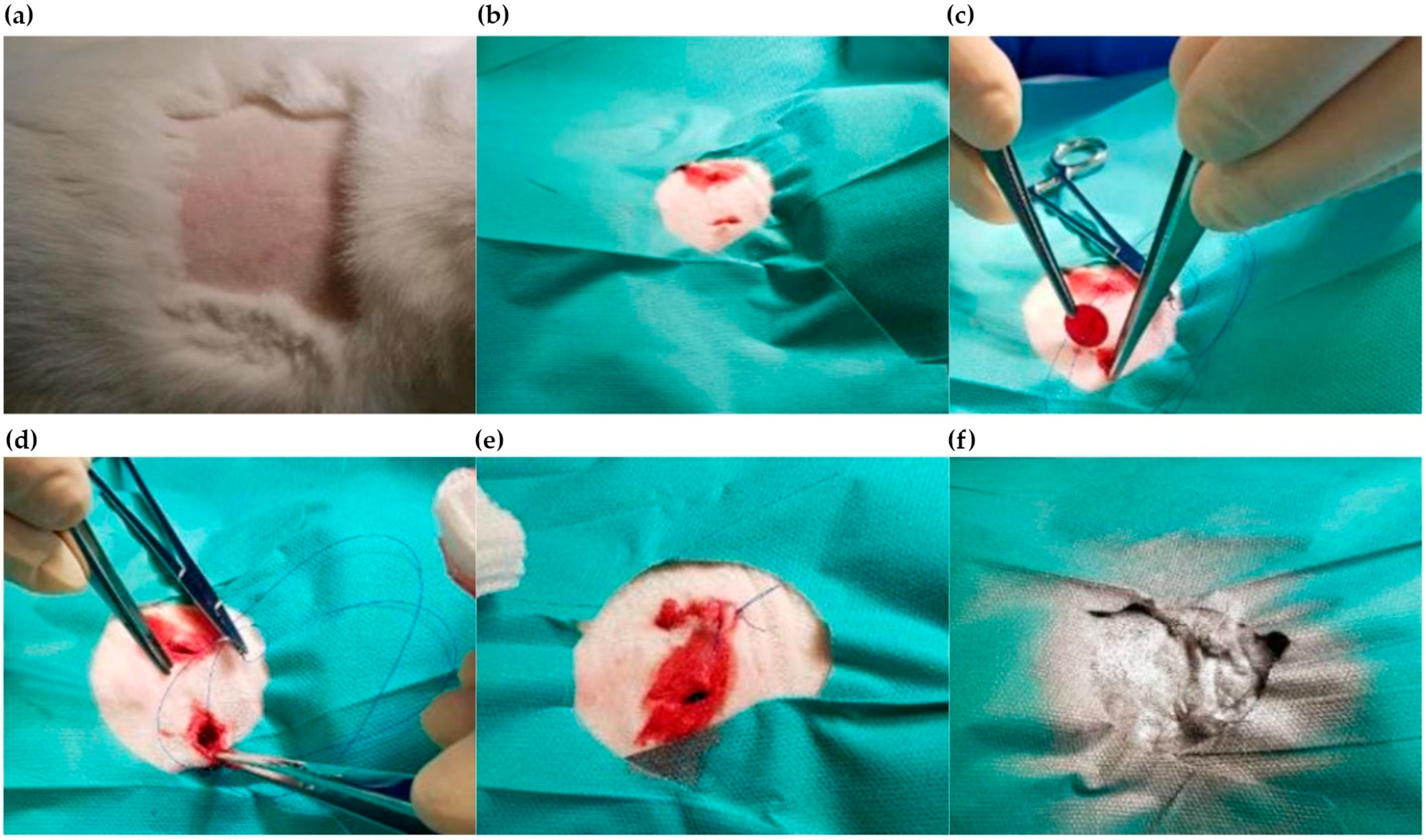
2.4.1. Implantation Process

Prior to surgery, the animals had blood drawn for diagnostic determinations. A mixture of xylazine and ketamine hydrochloride was then administered for premedication and anaesthesia. After premedication, the animals were prepared for surgery; the back was shaved, and the skin was washed with surgical field disinfectant (Figure 1a). Next, skin incisions were made over the longest dorsal muscle in an amount corresponding to the number of implants and a 15.0 × 15.0 mm pocket in the subcutaneous tissue was bluntly dissected (Figure 1b). A single sterile implant was inserted into the resulting single pocket in the group of test animals (14 mm diameter discs, 1.5 mm thick) (Figure 1c). The implant was secured against displacement in the subcutaneous tissue by suturing the specimen to the tissue with a non-absorbable suture (Figure 1d). The operation was repeated for both implants. The body shells were closed with a continuous suture (Figure 1e). In the control group, a skin incision was made, and the pocket was debrided, then the skin shells were closed as in the study group. The wound was protected with Aluspray (Figure 1f). To avoid dehydration and metabolic disturbances during the awakening period, the animals were given 20 mL of 0.9% NaCl and 10 mL of 5% glucose for each kg of body weight.

2.4.2. Clinical Observations

The observation of the animals lasted 4 weeks. The condition of the rabbits was monitored once a day for postoperative wound healing and animal behavior (stress evaluation, food and water intake). The animals were assessed based on the criteria, and for each subject of observation, the symptoms that could be observed were noted. These following criteria were based on the standards [29,30]
  • Breathing—dyspnoea (abdominal type, Kussmaul) apnoea, cyanosis, rapid breathing, nostril discharge.
  • Physical activity—decreased/increased somnolence, loss of upright posture, anaesthesia, catalepsy, ataxia, unusual way of moving, extreme exhaustion, tremor, muscle bunching tremor.
  • Convulsions—clonic, tonic, clonic–tonic, asphyxia, tetanic signs.
  • Reflexes—corneal, upright, muscle contractility, reaction to light, startle reflex.
  • Ocular symptoms—tearing, pupil constriction, pupil dilation, exophthalmos, opacity, iritis, conjunctivitis, red tears, drooping of the third eyelid.
  • Cardiovascular symptoms—bradycardia, tachycardia, impotence, vasodilation, vasoconstriction.
  • Salivation—salivation.
  • Hairstyling—scraggly hair.
  • Anaesthesia—decreased responsiveness.
  • Muscle tension—hypotonia, hypertonia.
  • Gastrointestinal symptoms—diarrhoea, vomiting.
  • Skin—swelling, erythema.

2.4.3. Termination of the Experiment

After 4 weeks of observation, humane euthanasia of the experimental animals was performed. Animals were blood drawn and then given premedication and Morbital to induce central cardiac and respiratory arrest. A macroscopic assessment of the surgical scar, the degree of wound healing, and the appearance of the tissue surrounding the implant was performed. Tissue sections surrounding the implant site were taken. In addition, the following were secured for histopathological analysis: the lymph node closest to the implant site and the organs heart, thymus, liver, spleen, kidney, and lung.

2.4.4. Diagnostic Tests

Determination performed on whole blood (CBC) was completed using a Mindray BC VET 2800 automated haematology analyzer (Mindray Animal Medical, The Hague, The Netherlands). Biochemical determinations: alanine aminotransferase (ALT), aspartate aminotransferase (AST), gammaglutamyltransferase (GGTP), lactate dehydrogenase (LDH), alkaline phosphatase (ALP), creatinine, and total protein were performed in serum obtained after whole blood clotting and subsequent centrifugation to separate the serum. Determinations were performed using an A25 automatic biochemical analyzer (from biosystems).

2.4.5. Sectional Assessment

After the animals were humanely terminated, a macroscopic assessment was carried out, including the appearance of the implantation site and the condition of the internal organs.

2.4.6. Histopathological Evaluation

During the post-mortem evaluation, organ and tissue sections were taken for histopathological evaluation. Tissues collected: skin from the implantation site, heart apex, lower lobe of the left lung, fragment of the left kidney, spleen, and liver. Tissues were fixed immediately after collection in 4% buffered formalin. Slides of the sections were prepared using the standard paraffin method and then stained using haematoxylin and eosin.

3. Results

3.1. Printing of Methacrylate Materials for Optimization Tests Prior to In Vivo Studies

The goal was to develop a 3D printing concept using two light engines to create a building field twice as big as usual with a total size of 128 mm × 160 mm (Figure 2a). The advantage is that the bigger field is combined with the high precision (same pixel size) as a small one. In the first step, the concept was finalized as one can see in Figure 2b. A prototype printer is shown in Figure 2c,d.
The whole construction is based on the usage of the “Firebird”—a light engine from IN-Vision. The main idea is to adapt the objective to fit to the construction shown in Figure 2. The optical path of the light engine is reflected as rectangular on the first surface mirror. The redirection of the optical path is necessary because the assembly of two firebirds right next to each other would result in a big gap (>1 cm) between the two projected building fields. Based on the optical requirements for 3D printing the rotors, the space constraints of the printer setup and the requirement to tile the images of the light engines, a specification for a new optical lens was defined. The optical design team at IN-VISION then developed a new lens according to that specification, i.e., a nominal optical design was developed. Then, to take into account manufacturing tolerances, comprehensive Monte Carlo analyses were performed in order to simulate the as-built performance of the optical system. The optical system was then iteratively optimized to become robust against manufacturing tolerances. After finishing the optical system design further, Monte Carlo simulations were performed to investigate the impact of different mirror surface properties on the optical quality of the system. Based on those simulations, the team concluded they were to use a λ/8 mirror. After finishing the lens design, the sourcing of the raw glass was started. In a next step, the mechanical design team at IN-VISION developed the mechanical layout of the lens. In Figure 2a, one can see light engine 1 and 2 (LE1 and LE2) and the mirror assembly. Further, the project team came to the conclusion that it is necessary that all of the movable parts (so light engine 1/2 and the two first surface mirrors) have adjustable degrees of freedom (DOFs) in the three Cartesian coordinates and three rotational ones around the axes. Beside this, the discussion about the necessary surface quality of the first surface mirrors was essential. If the quality is too poor the quality of the whole optical path becomes reduced. Based on the previously mentioned Monte Carlo simulations, the project team chose a λ/8 mirror—this means that the surface accuracy is higher than 632.8 nm/8 = 79.1 nm. The assembly should be measured in an automatic measurement system at In-Vision. Therefore, the design guarantees full access to all important reference plates on the light engines as well as to the focus-lock. With this system, it seems feasible to us to combine the two optical paths and create one big building field in the 3D printer. At IN-VISION, the next planned tasks are the sourcing and production of all parts and the assembly of the light engines with the newly developed lens. Specifications of the projection optics to fulfil the requirements within the project (Ra < 200 nm, Rz < 300 nm) have been defined below:
  • OO’—≥550 mm
  • Magnification—6.614 ± 1% (50 µm pixel size)
  • Aperture DMD—12° (F/2.4)
  • CTF at 10 Lp/mm—>75% as built
  • Wavelengths [nm] and weights—439 (0.1) 449 (0.5) 459 (1) 469 (0.5) 479 (0.1)
  • Distortion [%]—Need to have: <0.1, expected value < 0.05
  • Optics—Projection optics designed to include ~45 mm glass or similar
This treatment significantly increases methacrylate conversion to 91% using 1.6 wt% Irg784 as a photoinitiator. In addition, the effect of the choice and concentration of photoinitiator (PhI) in the resin system on methacrylate conversion was also studied. Aside from Irg784, the biocompatible germanium PhI Ivocerin was also studied. As shown in Table 1, a concentration of 2.4 wt.%. Irg784 leads to 86% methacrylate conversion immediately after printing, which increased to 95% after exposure (at 80 °C).

3.2. Optimisation of Biological Properties of Methacrylate-Based Materials

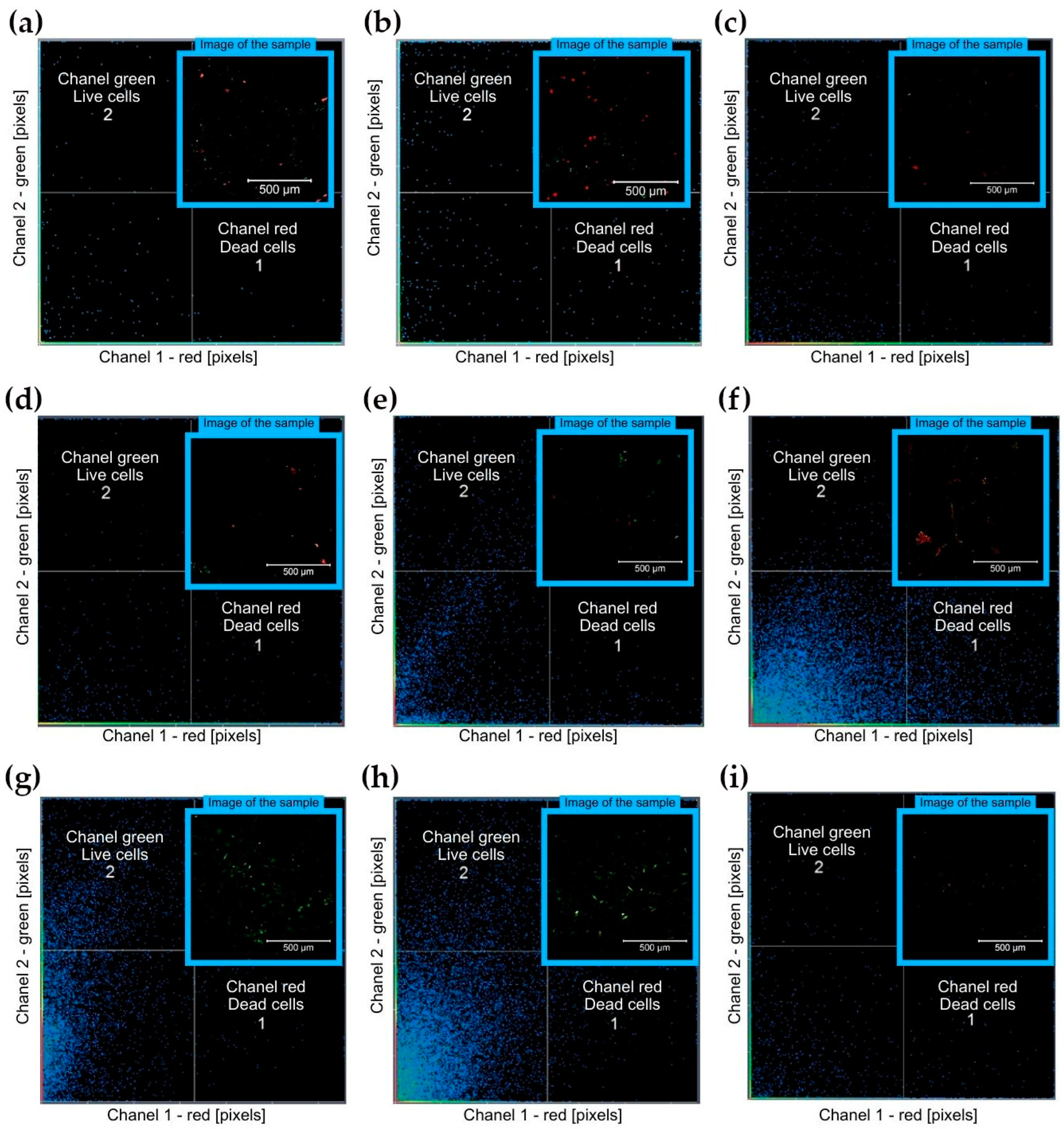
3.2.1. Direct Cytotoxity Analysis

The qualitative results of the direct cytotoxicity were shown in Figure 3, while the quantitative ones were given in Table 1. Following the colocalization function for samples 1–4, the higher pixel count corresponded first to dead cells, while later-on to the viable cells. It indicated the cytotoxic influence of the materials on the cells. The lowest cytotoxic effect was observed for sample no. 7. In the case of this sample, the surface has been modified with a titanium nitride layer. Comparing samples with the same phase composition and the same lighting temperature, one can see that the applied layers have improved material biocompatibility. A layer of titanium nitride significantly increased the number of living cells. The layer of a-CSiO:H reduced the number of dead cells.

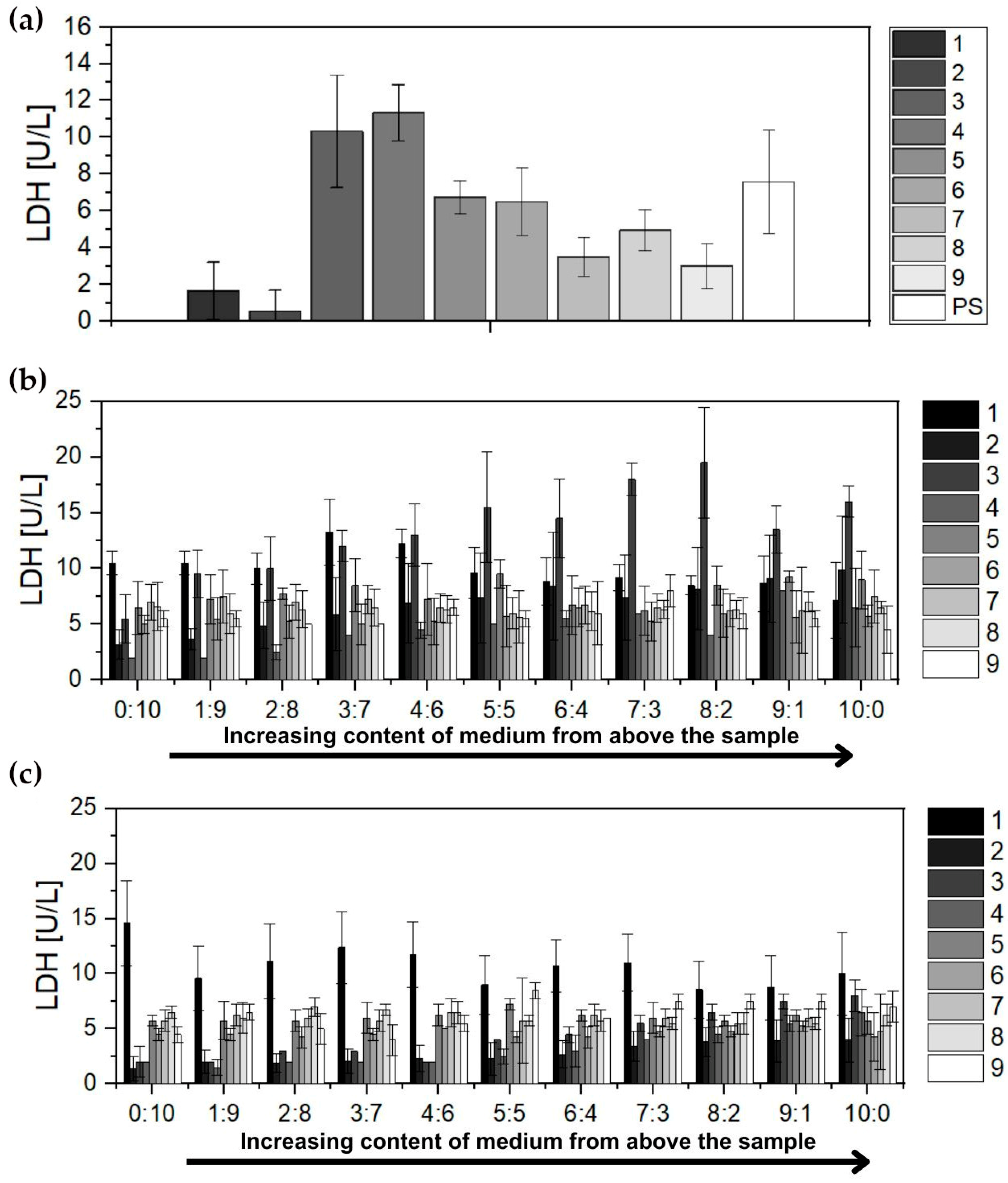
3.2.2. Lactate Dehydrogenase Analysis

Lactate dehydrogenase (LDH) levels were analyzed after direct contact with the sample and after an extract dilution tests.
Direct method. The results of the lactate dehydrogenase levels are shown in Figure 4a. In this study, polystyrene was used as a positive control, which has confirmed biocompatibility and is used in culture-dishes production.
From the test results obtained, a high level can be seen for materials M10 + 2 wt% DCP + 2.4 wt% Irgacure 784 + wt% 0.06 Quinoline Yellow post-processed in 70 °C and M10 + 2 wt% DCP + 2.4 wt% Irgacure 784 + wt% 0.06 Quinoline Yellow post-processed in 100 °C. The best properties for M10 + 1 wt% CNT + 0.8 wt% Omnirad 784, post-processed in 80 °C. Acceptable properties for M10 + 2 wt% DCP + 2.4 wt% Irgacure 784 + wt% 0.06 Quinoline Yellow, post-processed in 70 °C with TiN coating and M10 + 2 wt% DCP + 2.4 wt% Irgacure 784 + wt% 0.06 Quinoline Yellow, post-processed in 80 °C.
Extract dilution method. For extract dilution analyses, the cells were not in direct contact with the test material. The results of the analyses from the filtrate are shown in Figure 4b. Tests were performed for 24 h and 48 h, respectively. Based on the obtained results, it was concluded that the negative effect induced by contact with the test surface was small, irrespective of the duration of the experiment. Contact of the supplemented medium with the material did not adversely affect the quality of it, and it was mixed at different ratios with the pure medium and exposed into the cell culture.

3.3. In Vivo Tests on Small Animal Models

3.3.1. Clinical Observations

Observations of the animals were carried out based on the criteria given in Section 2.4.2. The results of the observations of the experimental animals are summarized in Figure 5.

3.3.2. Diagnostic Tests

Complete blood count (CBC). There were no significant changes in CBC results indicative of pathology. The results are presented in Table 2.
  • White blood cell count (WBC)—the mean leukocyte count determined for all groups was within the reference range throughout the observation period.
  • Erythrocyte count (RBC)—the mean erythrocyte count for all study groups determined throughout the observation period fluctuated in the lower reference range.
  • Total haemoglobin concentration (HGB)—the mean total concentration determined for all groups throughout the observation period was within the lower reference range.
  • Haematocrit (HCT)—the mean haematocrit value determined for all groups was within the lower reference range.
  • Platelet count (PLT)—the mean platelet count determined for all groups throughout the observation period was within the lower reference range.
Biochemical parameters. The biochemical parameters assessed can be divided into two categories: enzymes and metabolite concentrations. The following fluctuations in enzyme activity were found:
  • Alanine aminotransferase (ALT)—the mean activity of the enzyme determined for all groups during the observation period was above the reference range.
  • Aspartate aminotransferase (AST)—the mean activity of the enzyme in both groups fluctuated below the reference range.
  • Lactate dehydrogenase (LDH)—the mean activity of the enzyme determined for all groups during follow-up was within the normal range.
  • Gamma-glutamyltransferase (GGTP)—the mean activity of the enzyme in both groups before implantation of the test material was within the reference range. Before euthanasia, a slight increase in enzyme activity was observed in both groups above the reference range.
  • Alkaline phosphatase (ALP)—the mean enzyme activity for all groups determined during the observation period was below the reference range.
  • Other biochemical parameters were as follows:
  • Albumin—mean albumin concentrations for all throughout the observation period were above the reference range.
  • Creatinine—mean metabolite concentrations determined for both experimental groups before implantation and before euthanasia are within the reference range.
  • Urea—mean metabolite concentrations determined for all groups before euthanasia and before implantation were within the reference range.
  • Total protein—mean total protein concentrations fluctuated over the observation period for all groups within the lower limit of normal.

3.3.3. Post-Mortem Sectional Assessment

The experiment was completed as scheduled. Euthanasia of the animals was performed after 4 weeks of observation. Before premedication, blood was drawn from the animals for diagnostic tests from the marginal ear vein (approximately 4 mL). After premedication, Morbital was administered to induce central cardiac and respiratory arrest. A post-mortem examination included a macroscopic assessment of the surgical scar, the degree of wound healing, and the appearance of the tissue surrounding the implant, as well as an assessment of macroscopic changes in internal organs. Tissue sections surrounding the incision site were taken. Samples taken from lymph nodes, the nearest implant sites, and organs, such as the heart, thymus, liver, spleen, left kidney, and left lung, were secured for histopathological analyses. In the majority of animals, no significant changes were found in the area of the implantation site and in the abdominal and thoracic organs. Only in animal B7/8 an effusion was found within the implantation site.

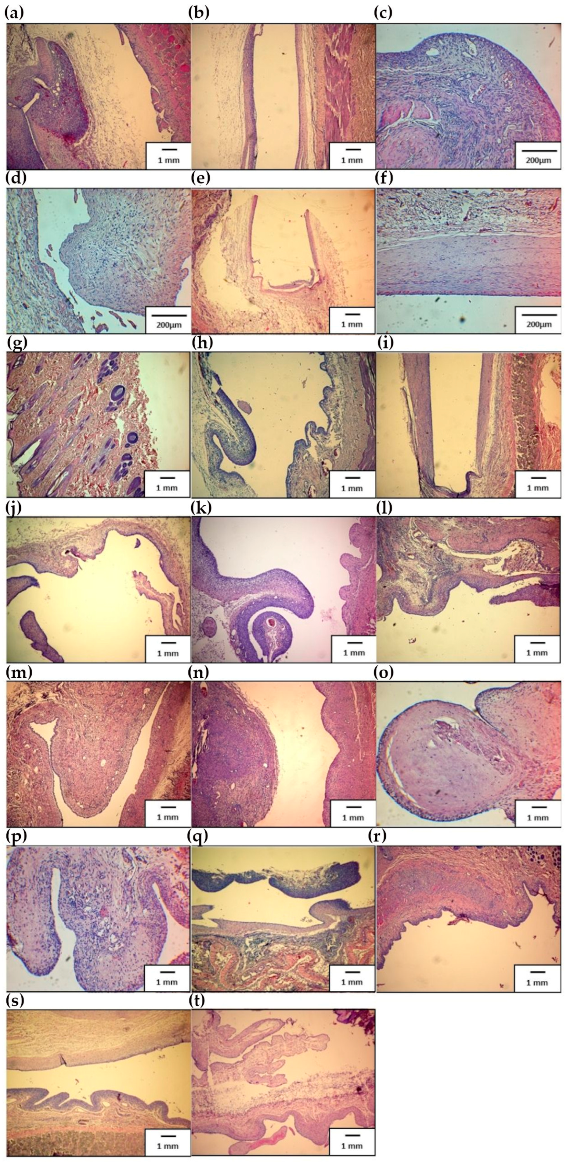
3.3.4. Histopathological Evaluation

Histopathological evaluation reveals no changes indicating a negative effect of the test material on experimental animals. No microscopic signs of toxicity in the form of sterile necrosis were observed at the implantation site. No unambiguous allergenicity in the form of an eosinophilic cellular response or granuloma formation was observed. It should be assumed that the inflammatory response, as well as the formation of polypoid proliferations, is an effect of an irritant, irrespective of the aetiology, whether mechanical or chemical.
The histological results of the longest dorsal muscle peri-implant tissues are shown in Figure 6. In the first specimen, labelled B1 (1) (Figure 6a), the topography of the lesion showed a centrally visible post-implantation fissure, with a bordered capsule on both sides. On the left side of the image, a polypoid granuloma with blood vessels and polypoid proliferation is visible, on the right—a thin layer of inflammatory granulation tissue adjacent to the muscle. In the second preparation, labelled B1 (2) (Figure 6b), the topography of the lesion showed a centrally visible post-implantation fissure, edged on both sides by a fibrous capsule. On the left was part of the capsule with a slight inflammatory infiltrate, and on the right, the capsule structure is poorly cellular.
Figure 6c,d show the results of B2 (1) and B2 (2) preparations, respectively. Figure 6c shows a granuloma with blood vessels and polypoid proliferation. Numerous blood vessels and a lymphocytic–histiocytic infiltrate are visible. The topography of the lesion shows a lack of a clearly defined post-implantation space. Fragments of a capsule of variable structure are visible. Figure 6d shows poorly collagenized connective tissue (loose connective tissue predominates) with an admixture of inflammatory infiltrate containing histiocytes, mast cells and lymphocytes, slightly swollen. The tissue is polyploidy proliferating. Faint capillaries are visible. Analysis of the topography of the lesion showed a lack of a clearly defined post-implantation space. Fragments of the capsule of the same structure are visible.
The results of specimen 3 are shown in Figure 6e. The topography of the lesion with a centrally visible U-shaped post-implantation fissure was edged with a thin connective tissue capsule. Connective tissue was visible all around. In Figure 6f, no typical implantation fissure is found. A linear connective tissue capsule is visible, without inflammatory infiltration, of varying thickness, containing fibroblasts and small capillary vessels with blood cells.
Figure 6g,h shows the histological analysis of preparation 4, labelled B4 (1) and B4 (2), respectively. Preparation B4 (1) (Figure 6g) does not contain an implantation fissure or pouch, but only a fragment of skin. In specimen B4 (2) (Figure 6h), the topography of the lesion showed a centrally visible post-implantation fissure, flanked by a pouch on both sides. On the left and right, polypoid proliferations of inflammatory granulation tissue with blood vessels are visible.
The results of specimen 5 are shown in Figure 6i,j. Topography of the lesion, in Figure 6i, showed a centrally visible U-shaped post-implantation fissure, edged by a thin connective tissue capsule, with connective tissue visible all around. The topography of the lesion, in Figure 6j, showed a post-implantation fissure, with the capsule with numerous polypoid connective tissue proliferations containing a diffuse inflammatory infiltrate. Analysis of specimen 6 was shown in Figure 6k,l for specimen 1 and Figure 6k for specimen no. 2. Figure 6k showed the topography of the lesion with a centrally visible post-implantation fissure with a bordered capsule on both sides. Polypoid proliferations can be seen on the left and right, with a prominent inflammatory infiltrate and granulation tissue on the left. The topography of the lesion in Figure 6l showed a richly cellular inflammatory granuloma forming a post-implantation capsule, with lymphocytic inflammatory infiltrates and an admixture of histiocytes forming polypoid proliferations.
Figure 6m,n shows the topography of the change of sample No. 7, labelled B7 (1), Figure 6m and B7 (2), respectively, and Figure 6n. A prominent fibrotic inflammatory granuloma forming a post-implantation capsule, sentinel with high cell numbers, lymphocytic inflammatory infiltrates and admixture of histiocytes is shown in Figure 6m. The granuloma forms polypoid proliferations. The topography of the lesion shown in Figure 6n shows a fibrotic inflammatory granuloma forming a post-implantation capsule, with lymphocytic infiltrates and admixture of histiocytes. The granuloma formed polypoid proliferations.
For the specimen labelled B8 (1) (Figure 6o), polypoid fibrous fragments of the implant capsule were present, focally with a lymphocytic inflammatory infiltrate. The lesion topography for specimen B8 (2) (Figure 6p) showed fibrotic polypoid inflammatory granular proliferations that form the wall of the implantation capsule, on top of the myxoid.
The lesion topography of slide B9 (1) (Figure 6q) shows a fibrous inflammatory granuloma forming a fibrous post-implantation capsule without inflammatory infiltration, slightly downwards, and fragments of polypoid inflammatory granuloma with a dense predominantly lymphocytic infiltration, slightly upwards. The lesion topography of slide B9 (2) shows a fibrotic inflammatory granuloma forming a post-implantation capsule with a slight inflammatory infiltrate, here and there forming polypoid proliferations—Figure 6r.
The topography of the lesion of the preparation labelled B10 (1) (Figure 6s) showed a centrally visible post-implantation fissure, rimmed with capsule on both sides. Above, the capsule was collagenized without inflammatory infiltration and downwards polypoid proliferations of inflammatory granules, and with marked inflammatory infiltration. In the case of specimen B10 (2), the implantation capsule was visible. It formed connective tissue polypoid proliferations as presented in Figure 6t.

4. Discussion

For the realization of the biocompatible resin system, a thiol-yne-methacrylate reactive system has been evaluated during the first step of the work. This reaction was based on a multiple-step radical mechanism leading to high monomer conversion and outstanding thermo-mechanical properties [31,32].
In the second step, the investigated and optimized resin system was evaluated in a 3D printing process in collaboration with Lithoz. It turned out that the functional group conversion of the monomers in the 3D printed parts (methacrylate conversion ~76% using 1.6 wt% Irgacure 784 (Irg784) as photoinitiator) is significantly lower as the conversion, which could be obtained in thin model films (conversion methacrylate >95%; see first evaluation report). This behavior could be explained by the lower intensity of the utilized light in the DLP-based printing process. Since methacrylates provide a significant cytotoxic potential, the amount of remaining methacrylate building blocks has to be decreased in the printed parts to the lowest possible level. Moreover, also the influence of the choice and concentration of the photoinitiator (PhI) in the resin system on the methacrylate conversion was investigated. Besides Irg784, the also-biocompatible Germanium-based PhI Ivocerin was tested. Based on the conducted experiments, it was finally observed that a 2.4 wt% Irg784 content leads to 86% methacrylate conversion directly after printing, which increased after a post-illumination (at 80 °C) to 95% [33,34,35].
In the following experiment, the effect of the post-curing on the thermo-mechanical properties using a dynamic mechanical analysis was investigated. It turned out that the additional illumination at elevated temperatures leads to a significant increase in the glass transition temperature. This can be explained by the higher network density obtained with progressive polymerization of uncured monomers. It needs to be mentioned that this post-treatment must be performed above the glass transition temperature of the printed photopolymer to facilitate monomer mobility in the polymeric network, enabling a subsequent polymerization reaction. Aside from the methacrylate conversion, the storage modulus at body temperature (~37 °C) also increased significantly from 252 to 1073 in the post-curing step.
The 3D printing technique used in present experiment needs to be improved in order to obtain a surface with greater smoothness, free of residual uncured polymer [36,37,38,39]. Non-contact quantitative evaluation of surface topography was completed in the present study. Using confocal microscopy, surface roughness parameters were measured. The images were taken at 20× and 50× magnification, and then the results were analyzed in ZEN 3.6 software, equipped with the Topography module that allows for obtaining the surface roughness parameters. Measurements were conducted both for samples before and after indentation tests. For each sample and each magnification, five measurements were made so that statistical analysis could be performed. The results of the quantitative surface topography analysis are shown in Figure 7a,b. The Ra parameter is the arithmetic mean deviation of the profile from the mean line. The highest value of this parameter was found for sample 1 (according to Table 1), for which the average value was 1.6 μm (Figure 7a). The other samples had at least twice the value of this parameter. It was noted that for the samples exposed at 70 °C, the value of the Ra parameter was twice less than the Ra values for the corresponding samples exposed at 100 °C. No effect of the applied layer on the surface roughness was noticed. The Rz parameter reports the height of roughness according to the ten points of the profile. The measure of this quantity is the average roughness. The highest value was obtained for samples 2 and 3 (according to Table 1) (Figure 7b). Sample 2 contained carbon nanotubes in its composition which may have affected the value of the Rz parameter. The lowest value of the analyzed Rz parameter can be seen for sample 5, illuminated at 70 °C, and for sample 8, illuminated at 100 °C.
High levels of roughness and surface defects promote platelet activation and adhesion, which has a negative impact on the use of the material in contact with blood. The applied surface modifications in the form of PVD- and ALD-applied layers yielded the expected results of increasing their mechanical properties, decreasing the roughness of the substrate and reducing cytotoxic effects [40,41,42,43]. The titanium nitride layer made using the ALD method presented much better properties (lower value of Ra parameter) than the layer of amorphous, hydrogenated, oxidized silicon carbide. Also, in cytotoxicity tests, the use of this layer achieved a cell survival rate of 98% for the sample illuminated at 70 °C and 87% for the sample illuminated at 100 °C. According to the provisions of standards [29,30] “A reduction in cell viability of more than 30% is considered a cytotoxic effect”; this means that samples coated with a layer of titanium nitride entail no cytotoxic effects. Analysis of cytotoxicity using LDH-lactate-dehydrogenase-level testing showed that all samples tested were within a standard deviation of the LDH level value for the control sample, which in this study was polystyrene. This result may indeed indicate the absence of a cytotoxic effect, but it is only when the results are matched with fluorescence analysis that the cytotoxic properties for the tested materials can be verified. Material biocompatibility is a complex mechanism, and no single test can fully determine the biocompatibility of a material, so additional testing, including in vivo testing, is necessary.
The clinical observations carried out up to date showed no significant changes during the experiments like the ones described presently [44,45]. The surgical wound healed without complications; the study material was not displaced. Diagnostic examinations showed no systemic inflammation (no leukocytosis), the morphological parameters remained normal, indicating that the biomaterial did not affect the bone marrow, and the haematopoietic process. The organs were characterized by normal performance. There were no significant changes in total protein, creatinine, urea, and total bilirubin. Elevated ALT and enzyme activities remained at similar levels for the control, study, and reference groups throughout the observation period. The activities of the other enzymes, i.e., AST, LDH, GGTP, and ALP, were characterized by a similar range of activity in all groups. Based on the collected data, no significant differences in the values of the assessed parameters were observed in the study group compared to the control group. Histopathological evaluation did not reveal changes indicative of a negative effect of the test material on experimental animals, as neither microscopic signs of toxicity in the form of sterile necrosis were observed at the implantation site. Additionally, no unambiguous allergenicity in the form of an eosinophilic cellular response or granuloma formation was observed. Therefore, the presently performed experiments allow the conclusion that the inflammatory response, as well as the formation of polypoid proliferations, is a response to an irritant, irrespective of the aetiology—whether mechanical or chemical.

Author Contributions

Conceptualization, R.M. and J.M.L.; methodology, M.G., E.J.-G. and M.S. (Marcin Surmiak); software, J.W. and K.J.; validation, M.S. (Martin Schwentenwein) and P.K.; formal analysis, R.M. and M.K.; investigation, E.J.-G., K.J., P.K., M.G. and M.S. (Marcin Surmiak); resources, J.W., J.M.L. and M.K.; data curation, E.J.-G. and J.W.; writing—original draft preparation, R.M., J.W., P.K. and M.S. (Martin Schwentenwein); writing—review and editing, R.M., J.W. and M.K.; visualization, J.W.; supervision, M.S. (Marcin Surmiak), M.S. (Martin Schwentenwein), R.M. and J.M.L.; project administration, J.W., R.M. and M.G.; funding acquisition, R.M. and M.G. All authors have read and agreed to the published version of the manuscript.

Funding

This research was funded by the Polish National Centre of Research and Development, grant no. 4DbloodROT M-ERA.NET 2017/4/2018 and the Austrian Research and Promotion Agency, grant no. FFG 865877. The study was carried out with the use of research infrastructure co-financed by the Polish Ministry of Infrastructure and Development, grant no. POIR.04.02.00-00-D023/20.

Institutional Review Board Statement

The study was conducted in accordance with the resolution code 25/2022 (date of approval 27 April 2022) of Medical University of Silesia (address: Medyków 4 St., 40-752 Katowice, Poland).

Informed Consent Statement

Not applicable.

Data Availability Statement

Data is contained within the article.

Conflicts of Interest

The authors declare no conflicts of interest. Martin Schwentenwein is an employee of the Lithoz GmbH company. The remaining authors declare that the research was conducted in the absence of any commercial or financial relationships that could be construed as a potential conflict of interest.

References

  1. Balcioglu, O.; Kahraman, Ü.; Ergi, D.G.; Karaca, S.; Engin, C.; Yagdi, T. Association of Age, Sex, and Heart Failure Etiology in Continuous Flow Left Ventricular Assist Device Patients. Transplant. Proc. 2022, 55, 1294–1296. [Google Scholar] [CrossRef] [PubMed]
  2. Eurotransplant International Foundation, Annual Report 2011. Available online: https://www.eurotransplant.org/wp-content/uploads/2019/12/ar_2011.pdf (accessed on 17 November 2023).
  3. Khatana, S.A.M.; Grandin, E.W.; Rame, J.E.; Shen, C.; Yeh, R.W.; Groeneveld, P.W. Medicaid Expansion and Ventricular Assist Device Implantation: An Analysis of the INTERMACS Registry. J. Am. Coll. Cardiol. 2020, 76, 1501–1502. [Google Scholar] [CrossRef] [PubMed]
  4. Zhang, M.; Tansley, G.D.; Dargusch, M.S.; Fraser, J.F.; Pauls, J.P. Surface Coatings for Rotary Ventricular Assist Devices: A Systematic Review. ASAIO J. 2022, 68, 623–632. [Google Scholar] [CrossRef] [PubMed]
  5. Miller, P.E.; Desai, N.R. Caution with Conclusions and Context of Mechanical Circulatory Devices-Reply. JAMA Intern. Med. 2023, 183, 277–278. [Google Scholar] [CrossRef] [PubMed]
  6. Consolo, F.; Pappalardo, F. Future Perspectives of Mechanical Circulatory Support with Left Ventricular Assist Devices: Lessons Learned from the HeartWare Ventricular Assist Device. ASAIO J. 2022, 68, 1–2. [Google Scholar] [CrossRef]
  7. Hullin, R.; Meyer, P.; Yerly, P.; Kirsch, M. Cardiac Surgery in Advanced Heart Failure. J. Clin. Med. 2022, 11, 773. [Google Scholar] [CrossRef]
  8. Milam, A.J.; Ramakrishna, H. Predicting Survival After HeartMate 3 Left Ventricular Assist Device Implantation-Progress Continues. J. Cardiothorac. Vasc. Anesth. 2023, 37, 1347–1348. [Google Scholar] [CrossRef] [PubMed]
  9. van der Heiden, C.W.; Zijderhand, C.F.; Veen, K.M.; Constantinescu, A.A.; Manintveld, O.C.; Brugts, J.J.; Bekkers, J.A.; Birim, O.; Bogers, A.J.J.C.; Caliskan, K. Mechanical Device Malfunction of the HeartMate II Versus the HeartMate 3 Left Ventricular Assist Device: The Rotterdam Experience. ASAIO J. 2023, 69, e80–e85. [Google Scholar] [CrossRef]
  10. Han, J.; Trumble, D.R. Cardiac Assist Devices: Early Concepts, Current Technologies, and Future Innovations. Bioengineering 2019, 6, 18. [Google Scholar] [CrossRef]
  11. Selzman, C.H.; Feller, E.D.; Walker, J.C.; Sheridan, B.C.; Silvestry, S.C.; Daly, R.C.; Anyanwu, A.C.; Madigan, D.; Liu, P.Y.; Frazier, O.H.; et al. The Jarvik 2000 Left Ventricular Assist Device: Results of the United States Bridge to Transplant Trial. ASAIO J. 2023, 69, 174–182. [Google Scholar] [CrossRef]
  12. Vieira, J.L.; Ventura, H.O.; Mehra, M.R. Mechanical circulatory support devices in advanced heart failure: 2020 and beyond. Prog. Cardiovasc. Dis. 2020, 63, 630–639. [Google Scholar] [CrossRef] [PubMed]
  13. Gawlikowski, M.; Major, R.; Mika, B.; Komorowski, D.; Janiczak, K.; Tkacz, E.; Tamulewicz, A.; Piaseczna, N. Semi-Quantitative Method of Assessing the Thrombogenicity of Biomaterials Intended for Long-Term Blood Contact. Materials 2023, 16, 38. [Google Scholar] [CrossRef] [PubMed]
  14. Major, R.; Wilczek, G.; Więcek, J.; Gawlikowski, M.; Plutecka, H.; Kasperkiewicz, K.; Kot, M.; Pomorska, M.; Ostrowski, R.; Kopernik, M. Hemocompatibile Thin Films Assessed under Blood Flow Shear Forces. Molecules 2022, 27, 5696. [Google Scholar] [CrossRef] [PubMed]
  15. Dyner, A.; Major, R.; Major, Ł.; Szewczenko, J.; Lukaszkowicz, K.; Barabaszová, K.; Krzywiecki, M.; Basiaga, M. Biological properties of surface modified 316 LVM steel. Arch. Civ. Mech. Eng. 2023, 23, 237. [Google Scholar] [CrossRef]
  16. Kurtyka, P.; Kopernik, M.; Kaczmarek, M.; Surmiak, M.; Major, Ł.; Kustosz, R.; Więcek, J.; Kurtyka, K.; Bartkowiak, A.; Major, R. Biofunctional impact of textured coatings in the application of heart assist therapy. Arch. Civ. Mech. Eng. 2023, 23, 31. [Google Scholar] [CrossRef]
  17. Major, R.; Surmiak, M.; Gawlikowski, M.; Schwarz, R.; Kot, M.; Wiecek, J.; Lackner, J.M. Novel Hemocompatible Thiol-yne Based Photopolymers Obtained by the Advanced Stereolithography (SLA) Processing with Strongly Improved Surface Smoothness by a Novel Exposition Approach for Anti-aliasing. In Innovations in Biomedical Engineering. Lecture Notes in Networks and Systems; Gzik, M., Paszenda, Z., Piętka, E., Tkacz, E., Milewski, K., Jurkojć, J., Eds.; Springer: Cham, Switzerland, 2023; Volume 409, pp. 199–215. [Google Scholar] [CrossRef]
  18. Rab, T.; O’Neill, W. Mechanical circulatory support for patients with cardiogenic shock. Trends Cardiovasc. Med. 2019, 29, 410–417. [Google Scholar] [CrossRef]
  19. Urbanowicz, T.; Olasińska-Wiśniewska, A.; Michalak, M.; Bociański, M.; Krawczyk, D.; Straburzyńska-Migaj, E.; Wachowiak-Baszyńska, H.; Jemielity, M. Risk of Thrombus Formation in Patients on Mechanical Circulatory Support with POLVAD-MEV. Ann. Transplant. 2021, 26, e926555–e926563. [Google Scholar] [CrossRef]
  20. Kounis, N.G.; Soufras, G.D.; Davlouros, P.; Tsigkas, G.; Hahalis, G. Thrombus Formation Patterns in HeartMate II Continuous-Flow Left Ventricular Assist Devices: A Multifactorial Phenomenon Involving Kounis Syndrome? ASAIO J. 2014, 60, 369–371. [Google Scholar] [CrossRef]
  21. Dignat-George, F.; Boulanger, C.M. The many faces of endothelial microparticles. Arterioscler. Thromb. Vasc. Biol. 2022, 31, 27–33. [Google Scholar] [CrossRef]
  22. Roka-Moiia, Y.; Miller-Gutierrez, S.; Palomares, D.E.; Italiano, J.E.; Sheriff, J.; Bluestein, D.; Slepian, M.J. Platelet Dysfunction during Mechanical Circulatory Support: Elevated Shear Stress Promotes Downregulation of αIIbβ3 and GPIb via Microparticle Shedding Decreasing Platelet Aggregability. Arterioscler. Thromb. Vasc. Biol. 2021, 41, 1319–1336. [Google Scholar] [CrossRef]
  23. Lantada, A.D.; de Blas Romero, A.; Schwentenwein, M.; Jellinek, C.; Homa, J. Lithographybased ceramic manufacture (LCM) of auxetic structures: Present capabilities and challenges. Smart Mater. Struct. 2016, 25, 054015. [Google Scholar] [CrossRef]
  24. Zanchetta, E.; Cattaldo, M.; Franchin, G.; Schwentenwein, M.; Homa, J.; Colombo, P. Stereolithography of SiOC Ceramic Microcomponents. Adv. Mater. 2016, 28, 370–376. [Google Scholar] [CrossRef] [PubMed]
  25. Schwentenwein, M.; Homa, J. Additive Manufacturing of Dense Alumina Ceramics. Int. J. Appl. Ceram. Technol. 2015, 12, 1–7. [Google Scholar] [CrossRef]
  26. Romero, A.B.; Pfaffinger, M.; Mitteramskogler, G.; Schwentenwein, M.; Jellinek, C.; Homa, J.; Stampfl, J. Lithography-based additive manufacture of ceramic biodevices with design controlled surface topographies. Int. J. Adv. Manuf. Technol. 2016, 88, 1547–1555. [Google Scholar] [CrossRef]
  27. Ligon-Auer, S.C.; Schwentenwein, M.; Gorsche, C.; Stampfl, J.; Liska, R. Toughening of photo-curable polymer networks: A review. Polym. Chem. 2016, 7, 257–286. [Google Scholar] [CrossRef]
  28. Slaughter, M.S.; Rogers, J.G.; Milano, C.A.; Russell, S.D.; Conte, J.V.; Feldman, D.; Sun, B.; Tatooles, A.J.; Delgado, R.M.; Long, J.W.; et al. Advanced Heart Failure Treated with Continuous-Flow Left Ventricular Assist Device. NEJM 2009, 361, 2241–2251. [Google Scholar] [CrossRef] [PubMed]
  29. ISO 10993-6:2016; Biological Evaluation of Medical Devices; Part 6: Tests for Local Effects after Implantation. ISO: Geneva, Switzerland, 2016.
  30. ISO 10993-11:2017; Biological Evaluation of Medical Devices; Part 11: Tests for Systemic Toxicity. ISO: Geneva, Switzerland, 2017.
  31. Oesterreicher, A.; Ayalur-Karunakaran, S.; Moser, A.; Mostegel, F.H.; Edler, M.; Kaschnitz, P.; Pinter, G.; Trimmel, G.; Schlögl, S.; Griesser, T. Exploring thiol-yne based monomers as low cytotoxic building blocks for radical photopolymerization. J. Polym. Sci. Part A Polym. Chem. 2016, 54, 3484–3494. [Google Scholar] [CrossRef]
  32. Oesterreicher, A.; Gorsche, C.; Ayalur-Karunakaran, S.; Moser, A.; Edler, M.; Pinter, G.; Schlögl, S.; Liska, R.; Griesser, T. Exploring Network Formation of Tough and Biocompatible Thiol-yne Based Photopolymers. Macromol. Rapid Commun. 2016, 37, 1701–1706. [Google Scholar] [CrossRef]
  33. Oesterreicher, A.; Moser, A.; Edler, M.; Griesser, H.; Schlögl, S.; Pichelmayer, M.; Griesser, T. Investigating Photocurable Thiol-Yne Resins for Biomedical Materials. Macromol. Mater. Eng. 2017, 19, 1600450. [Google Scholar] [CrossRef]
  34. Oesterreicher, A.; Wiener, J.; Roth, M.; Moser, A.; Gmeiner, R.; Edler, M.; Pinter, G.; Griesser, T. Tough and degradable photopolymers derived from alkyne monomers for 3D printing of biomedical materials. Polym. Chem. 2016, 7, 5169–5180. [Google Scholar] [CrossRef]
  35. Quick, A.S.; Pereira, A.S.; Bruns, M.; Bückmann, T.; Rodriguez-Emmenegger, C.; Wegener, M.; Barner-Kowollik, C. Rapid Thiol-Yne-Mediated Fabrication and Dual Postfunctionalization of Micro-Resolved 3D Mesostructures. Adv. Funct. Mater. 2015, 25, 3735–3744. [Google Scholar] [CrossRef]
  36. Norbert, M.; Wolfgang, W.; Christoph, A.; Volker, R.; Robert, L.; Juergen, S.; Johannes, P. Light Hardening Dross for Stereolithographic Production of Dental Ceramics. EP2151214 (A1), 10 February 2010. Also Published as: US2010029801 (A1), JP2010031279 (A). Available online: https://patents.google.com/patent/EP2404590A1/en (accessed on 24 November 2023).
  37. Gottfried, R.; Wolfgang, W.; Christoph, A.; Johannes, P.; Juergen, S. Device and Method for Processing Light-Polymerizable Material for the Layered Assembly of Molds. WO2010045950 (A1), 29 April 2010. M-ERA.NET Call 2017; p. 17. Available online: https://patents.google.com/patent/US9067359 (accessed on 24 November 2023).
  38. Robert, L.; Johannes, P.; Juergen, S.; Wolfgang, W.; Christoph, A. Device and Method for Processing Light-Polymerizable Material for Building up Object in Layers. WO2010045951 (A1), 29 April 2010. Available online: https://eureka.patsnap.com/patent-US8741203B2 (accessed on 24 November 2023).
  39. Gottfried, R.; Wolfgang, W.; Juergen, S.; Johannes, P.; Johannes, H. Method and Device for Generative Production of a Mould with Non-Planar Layers. EP2251185 (A1), 17 November 2010. Also published as: US2010283188 (A1), JP2010259804 (A). Available online: https://patents.google.com/patent/US20100283188 (accessed on 24 November 2023).
  40. Lutzer, M.; Hummer, S.; Simsek, S.; Zimmermann, C.; Amsuessb, A.; Hutter, H.; Detz, H.; Stoeger-Pollach, M.; Bethge, O.; Bertagnolli, E. Rhodium Germanide Schottky Barrier Contacts. ECS J. Solid State Sci. Technol. 2015, 4, 387–392. [Google Scholar] [CrossRef]
  41. Lutzer, M.; Simsek, S.; Zimmermann, C.; Stoeger-Pollach, M.; Bethge, O.; Bertagnolli, E. Linearity optimization of ALD-grown ZrO2 MIM capacitors by inserting interfacial Zr-doped chromia layers. J. Appl. Phys. 2016, 119, 125304. [Google Scholar] [CrossRef]
  42. Zimmermann, C.; Bethge, O.; Winkler, K.; Lutzer, B.; Bertagnolli, E. Improving the ALD-grown Y2O3/Ge interface quality by surface and annealing treatments. Appl. Surf. Sci. 2016, 369, 377–383. [Google Scholar] [CrossRef]
  43. Zimmermann, C.; Bethge, O.; Lutzer, B.; Bertagnolli, E. Platinum-assisted Post Deposition annealing of the n-Ge/Y2O3 Interface. Semicond. Sci. Technol. 2016, 31, 075009. [Google Scholar] [CrossRef]
  44. Gross, B.C.; Erkal, J.L.; Lockwood, S.Y.; Chengpeng, C.; Spence, D.M. Evaluation of 3D printing and its potential impact on biotechnology and the chemical sciences. Anal. Chem. 2014, 86, 3240–3253. [Google Scholar] [CrossRef]
  45. Schuster, M.; Turecek, C.; Kaiser, B.; Stampfl, J.; Liska, R.; Varga, F. Evaluation of Biocompatible Photopolymers I: Photoreactivity and Mechanical Properties of Reactive Diluents. J. Polym. Sci. Part A Polym. Chem. 2007, 44, 547–557. [Google Scholar] [CrossRef]
Figure 1. Preparation for in vivo experiment (a) shaving skin on animal’s back, (b) draping site with a sterile drape, (c) making an incision on right and left side of the back, (d) placing one subcutaneous pocket implant each and lining discs, (e) closing wound over test material, (f) protecting wound with AluSpray.
Applsci 14 00383 g001
Figure 2. Concept of printer dedicated to methacrylates: (a) system overview, (b) conceptual diagram, (c) printer prototype dedicated to printing a model of the rotor of a cardiac assist pump, overview drawing, and (d) projection system in measuring device with first integrated light engine.
Applsci 14 00383 g002
Figure 3. Dissected images, presented as colocalization, characterizing overlap of channels within given pixel space of the cell viability and cytotoxicity assessed using direct tests from confocal microscope. Human dermal fibroblast on tested materials in 24-well plates and cultured for 24 h. The green color indicates excitation at a wavelength around 490 nm with FDA (fluorescein tetraacetate) and red color around 560 with PI (propidium iodide). (a) Sample 1, (b) Sample 2, (c) Sample 3, (d) Sample 4, (e) Sample 5, (f) Sample 6, (g) Sample 7, (h) Sample 8, (i) Sample 9.
Applsci 14 00383 g003
Figure 4. (a) LDH levels of human fibroblasts’ supernatants assessed after 48 h direct incubation with tested materials in cell culture. Results were obtained during three independent experiments and are presented as mean ± SD. (b,c) LDH levels in cell culture supernatants of human dermal fibroblasts cultured in full growth medium supplemented with different dilutions of extracts of tested materials. Panel (b) after 24 h incubation; panel (c) after 48 h incubation. Results were obtained during three independent experiments and are presented as mean ± SD.
Applsci 14 00383 g004
Figure 5. View of wound changes observed at post-mortem examination in study group on day 11 observation. (a) Animal in good condition. Treatment wound healed. (b) Animal in good condition. Treatment wound healed. (c) Animal in good condition. Slight spreading of treatment wound. (d) Animal in good condition. Treatment wound healed. (e) Animal in good condition. Treatment wound healed. (f) Animal in good condition. Treatment wound healed. (g) Animal in good condition. Treatment wound healed. (h) Animal in good condition. Treatment wound healed. (i) Animal in good condition. Treatment wound healed. (j) Animal in good condition. Treatment wound healed. Summary of changes observed at autopsy in control group, observation of postoperative wound on day 11 of observation. (k) Animal in good condition. Treatment wound healed. (l) Animal in good condition. Treatment wound healed. (m) Animal in good condition. Surgical wound healed. (n) Animal in good condition. Surgical wound healed. (o) Animal in good condition. Slight spreading of treatment wound.
Applsci 14 00383 g005
Figure 6. Histological analysis of peri-implant tissues (longest dorsal muscle) for each animal of study group. Staining based on haematoxylin and eosin method. Hematoxylin-stained basophilic structures, purple (e.g., cell nucleus); eosin-stained eosinophilic structures, pink (e.g., cytoplasm). (a) First animal—specimen marked as B1 (1). (b) First animal—specimen marked as B1 (2). (c) Second animal—specimen marked as B2 (1). (d) Second animal—specimen marked as B2 (2). (e) Third animal—specimen marked as B3 (1). (f) Third animal—specimen marked as B3 (2). (g) Fourth animal—specimen marked as B4 (1). (h) Fourth animal—specimen marked as B4 (2). (i) Fifth animal—specimen marked as B5 (1). (j) Fifth animal—specimen marked as B5 (2). (k) Sixth animal—specimen marked as B6 (1). (l) Sixth animal—specimen marked as B6 (2). (m) Seventh animal—specimen marked as B7 (1). (n) Seventh animal—specimen marked as B7 (2). (o) Eight animal—specimen marked as B8 (1). (p) Eight animal—specimen marked as B8 (2). (q) Ninth animal—specimen marked as B9 (1). (r) Ninth animal—specimen marked as B9 (2). (s) Tenth animal—specimen marked as B10 (1). (t) Tenth animal—specimen marked as B10 (2).
Applsci 14 00383 g006
Figure 7. (a) Values of Ra parameters for the tested materials. (b) Values of Rz parameters for the tested materials.
Applsci 14 00383 g007
Table 1. Quantitative analysis of direct cytotoxicity, analyzed using confocal microscopy technique.
No.MaterialPost-ProcessingSurface ModificationRed Channel—Dead Cells [Pixels]Green Channel—Live Cells [Pixels]
1M10 + 0.8% Omnirad 78480 °Cno coating1895.82948.17
2M10 + 1 wt% CNT + 0.8 wt% Omnirad 78480 °Cno coating2435.41634.33
3M10 + 2 wt% DCP + 2.4 wt% Irgacure 784 + wt% 0.06 Quinoline Yellow70 °Cno coating1156.80109.90
4M10 + 2 wt% DCP + 2.4 wt% Irgacure 784 + wt% 0.06 Quinoline Yellow100 °Cno coating706.90117.10
5M10 + 2 wt% DCP + 2.4 wt% Irgacure 784 + wt% 0.06 Quinoline Yellow70 °CPECVD a-CSiO:H228.15351.76
6M10 + 2 wt% DCP + 2.4 wt% Irgacure 784 + wt% 0.06 Quinoline Yellow100 °CPECVD a-CSiO:H142.71139.00
7M10 + 2 wt% DCP + 2.4 wt% Irgacure 784 + wt% 0.06 Quinoline Yellow70 °CALD TiN57.214387.71
8M10 + 2 wt% DCP + 2.4 wt% Irgacure 784 + wt% 0.06 Quinoline Yellow100 °CALD TiN239.071665.33
9M10 + 2 wt% DCP + 2.4 wt% Irgacure 784 + wt% 0.06 Quinoline Yellow80 °Cno coating159.00170.00
Table 2. CBC and biochemical parameters summary.
Evaluated GroupParameterNormal Range for AnimalsControl Group—ImplantationStudy Group—ImplantationConrol Group—EuthanasiaStudy Group—Euthanasia
UnitMeanStd. Dev.MeanStd. Dev.MeanStd. Dev.MeanStd. Dev.
WBC(×109/L)5.2–13.56.081.465.931.376.461.367.862.25
RBC(×1012/L)5–7.65.350.345.440.325.020.315.330.42
HGB(g/L)105–170115.009.27112.905.20112.007.58115.606.62
HCT(%)31–46.033.622.8333.181.5832.262.4633.171.76
PLT(×109/L)100–512184.6033.76126.2052.65172.4079.58194.3032.32
ALT(U/L)31–53110.0238.7381.2937.11107.9250.4495.4959.78
AST(U/L)42–9834.6617.1542.1943.3640.1020.0541.4327.50
Cr(mg/dL)0.5–2.71.770.131.710.171.530.091.540.18
LDH(U/L)59–389114.2226.25120.6350.5299.7034.01150.0080.15
TP(g/L)60–8359.504.3756.694.0260.421.6759.152.91
Urea(mg/dL)26–8451.006.5844.693.9447.885.6543.935.61
Disclaimer/Publisher’s Note: The statements, opinions and data contained in all publications are solely those of the individual author(s) and contributor(s) and not of MDPI and/or the editor(s). MDPI and/or the editor(s) disclaim responsibility for any injury to people or property resulting from any ideas, methods, instructions or products referred to in the content.

