Abstract
Introduction: Cone Beam Computed Tomography (CBCT) scans should be digitally oriented using a reference plane before being evaluated for patient growth and treatment outcome. Current orientation planes are usually dependent on the Porion points. Using more reliable landmarks than the Porion, we introduce the Acta plane and investigate its reliability as an alternative reference plane for cases in which the Porion point is inaccessible. Methods: To test its reliability, a dental student and an orthodontist located sixteen skeletal and dental landmarks in sixteen CBCT scans before and after reorientation. Also, four measurements were calculated based on these landmarks’ coordinates. The reorientation of these CBCT scans with the Acta plane was performed by another dental student. The Intraclass Correlation Coefficient (ICC) was calculated before and after orientation, as well as the intra and inter-examiner. The data were tested for significance through the Shapiro–Wilk test with a threshold set at 0.05. Through the ICC variation of the points’ coordinates, this article also evaluated the reliability of this plane with the t-paired and exact-sign tests. Results: The identification of landmarks was more reliable in the reoriented CBCT images than in the original images, with a significant increase of 0.012 in the median of the ICC. Linear and angular measures showed no significant differences between groups. Conclusion: This plane is a reliable alternative for the orientation of CBCT images. The design of the Acta plane might allow the use of a smaller field of view and, consequently, a reduction in the radiation dose.
1. Introduction
In orthodontics, patient records are used for documentation, diagnosis, planning, and evaluation of the outcome of treatment [1,2,3,4]. Although 2D panoramic and cephalometric radiographs have been the standard procedure in orthodontics for a long time, they present limitations such as distortions, superimposition of bilateral structures, and variable enlargement ratios [3,5,6,7]. In more complex cases, such as surgical or asymmetry cases and cases involving impacted teeth, patients, and orthodontists benefit from a three-dimensional (3D) evaluation [8,9,10].
In the late 1990s, Cone Beam Computed Tomography (CBCT) technology made it possible to generate 3D skull images efficiently at reasonable cost and radiation levels [3]. It also provides high-resolution images, volumetric assessment of structures, options for 3D reconstruction, and easier access to bilateral structures than a two-dimensional (2D) image [3]. Application of CBCT is expected to increase [8], and although the radiation dose requires critical consideration [6], drastic reductions are possible by modulating CBCT parameters such as the field of view [11,12,13].
To analyze and quantify changes in the morphology of the dentofacial complex brought by growth or treatment results, radiographs are taken at different stages and are then evaluated and might even be superimposed [14]. CBCT scans are an adequate choice for this purpose because they are reproducible and consistent regarding landmark identification and measurements, with similar or even higher reliability than 2D cephalometrics [6,15,16]. Regarding image superimposition, CBCT scans are just as reliable as 2D cephalometrics [14]. However, reliability in determining landmarks is dependent on the chosen anatomic point or structure, on the examiner’s expertise, and on the scan orientation [17,18,19].
In a cephalometric radiograph, the physical position of the patient’s head during the acquisition permanently affects the final image [20,21]. During the acquisition of the CBCT image, the patient’s position (standing or lying) and the resultant physical orientation of the patient’s head are important, as they can affect the mandibular position and, consequently, the airways. However, slight variances in head position may have a limited effect on the final image and still influence the ability of the examiner to locate an anatomical structure efficiently. This problem is easily solved in the CBCT imaging technique because the final 3D image can always be virtually oriented after being taken. In order to measure changes as a result of treatment or growth, CBCT images should be similarly acquired and oriented. However, it is virtually impossible to deliver two CBCT images in which the skull is exactly and precisely positioned in the same direction. Different orientations of CBCT images might influence the operator’s ability to identify landmarks and perform measurements, affecting the vertical measurements [22]. The orientation of the scan also affects 3D model segmentation [23]. Therefore, it is essential to virtually orient the CBCT images in order to improve the reliability in landmark detection, measurements, and segmentation.
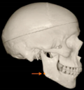
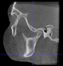
Traditionally, this orientation can be performed with the assistance of a reference plane, and the standard reference plane for 2D cephalometric tracings is the Frankfort Horizontal Plane (FHP) [24]. Therefore, the FHP was automatically applied as a reference for the orientation of 3D images. This plane is delimited by the right and left Porion points (the most superior-posterior margins of the most external point of the external acoustic meatus) and the most inferior points of the lower margins of both Orbitas. Although this plane has been considered a reliable orientation reference in multiplanar reconstructed magnetic resonance images [25,26], it is highly dependent on the Porion points. The right and left Porion points are challenging to locate, have poor reproducibility in CBCT scans, are positioned in curved areas, and are, frequently, asymmetric; for these reasons, they might not be shown due to a limited field of view or when the patient’s head is tilted [12,17,27,28,29].
Given the technical difficulties in identifying Porion for defining the FHP, a new reference plane is presented, the Acta plane, which stands for Academisch Centrum Tandheelkunde Amsterdam. Instead of Porions, this plane is defined by reference points more central to the skull. Therefore, the aim of this study was to determine whether the newly defined Acta plane affects the examiner’s reliability when locating anatomical landmarks and performing measurements.
Cone Beam Computed Tomography (CBCT) has transformed imaging with superior 3D skull images, offering enhanced resolution. It competently analyzes dentofacial changes, comparable to or surpassing 2D cephalometrics. However, the precision of landmarks depends on factors like anatomy, examiner expertise, and scan orientation. CBCT addresses challenges in 2D cephalometrics using virtual orientation, yet it struggles to reproduce identical skull positioning. The Acta plane, introduced due to difficulties with the traditional Frankfort Horizontal Plane (FHP) relying on hard-to-locate Porion points, aims to offer an alternative.
Given the flexibility of the new CBCT scans with adjustable software to quantify the desired field of view, opting for the Acta plane over the Frankfort Horizontal Plane or other reference planes relying on more external landmarks is expected to significantly decrease radiation exposure. These adjustments can be seamlessly integrated into routine clinical procedures.
2. Material and Methods
The sample consisted of 16 CBCT images of patients in permanent dentition, between 8 and 13 years old (mean 11.42 years, SD 1.31), in need of Rapid Maxillary Expansion (RME), with good quality CBCT, obtained with the same protocol, treated at the Orthodontics Clinic at the School of Health and Life Sciences of Pontificia Universidade Catolica do Rio Grande do Sul. All CBCT images were acquired with a volumetric scanner (model I-Cat Next-Generation Imaging Science International, Hatfield, PA, USA) using the following settings: 120 kV, 8 mA, exposure time 40 s, protocol FULL, and a voxel resolution varying from 0.25 to 0.30 mm3. The Institutional Research Ethics Committee approved this retrospective study under protocol number 10/05093.
In this study, the goal was to evaluate the Acta plane and not the growth or treatment outcome. Therefore, the same scan was compared with and without orientation. The scans before and after the RME were neither compared nor superimposed.
Three examiners participated in this study: two dental students and one orthodontist. The dental students underwent a calibration period under supervision, and the orthodontist had already worked extensively with CBCT images. Examiners 1 (dental student) and 2 (orthodontist) located the landmarks in the multiplanar axial, sagittal, and coronal slices during the same period of time. To determine intra-examiner reliability, the location of the landmarks was repeated at a 1-week interval. Subsequently, examiner 3 (dental student) reoriented the scans, identifying the landmarks of the plane himself. Examiners 1 and 2 then located the landmarks on the reoriented images. To assess intra-examiner reliability, the landmarks were randomly relocated two days later, and the examiners were not blinded for this landmark identification. Data involving landmark distances and measurements were later calculated by examiner 2. The examiners were not involved with CBCT scanning procedures or orthodontic treatment.
Landmarks and measurements were selected based on the previous study by Meijer et al. [30] that added to the landmarks that define the Acta plane. The following landmarks were chosen for this research: Nasion (Na), Sella (Se), Basion (Ba), Pogonion (Pog), Gonion (Go), Mandibular Fossa (MF), Orbita (Or), Lateral Orbita (OrbitaLat), Porion (Po), and Root Tip (TL.6). The definition of the landmarks and measurements are listed in Table 1.

Table 1.
Description of landmarks.
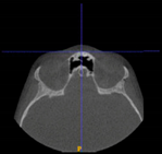
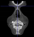
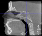
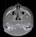
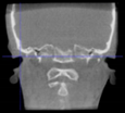
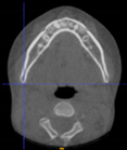
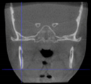
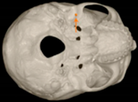
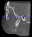
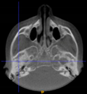
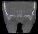
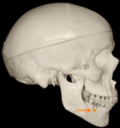
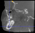
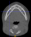
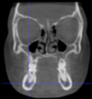
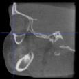
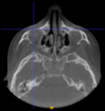
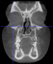
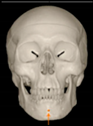
Three points determined the Acta plane: O, F right (FR), and F left (FL) (Table 2). Point O is the midpoint between the most craniodorsal point of the dorsum Sella and the most posterior dorsal point of the Basion in the midsagittal plane (Figure 1). Both points F are a result of the intersection between two lines: the line that connects the most inferior points of the lower orbital margins, right and left, and a line perpendicular to this line that runs through the most external points of the orbital margins, right and left (Figure 2). The new transverse reference plane, the Acta plane (Figure 2), is created by connecting the O-point (Figure 1) with FR and FL (Figure 2).
Table 2.
Description of the reference-plane points.
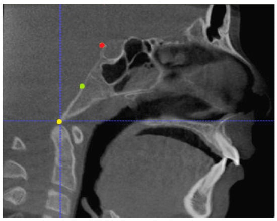
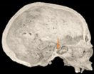
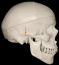
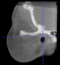
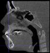
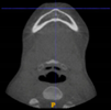
Figure 1.
Point O (green dot) is the midpoint between the dorsum Sella (Se) (red dot) and the Basion point (Ba) (yellow dot).
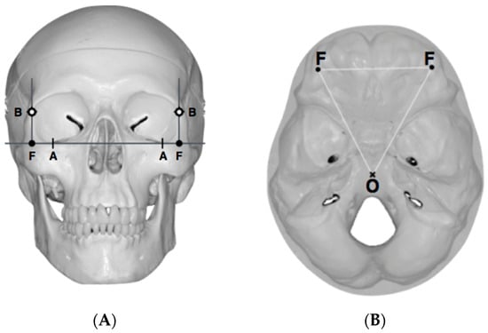
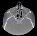
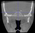
Figure 2.
(A) Construction of the F-points (right and left), frontal view. The F-points are originated from the intersection between the line connecting points A (the most inferior point of the lower orbit) and the perpendicular line to it that passes through points B (most external/lateral point of the Orbita). (B) Transverse view of the ACTA plane.
CBCT Reorientation and Coordinate Transformation Procedure
After determining the coordinates of the landmarks relevant to the Acta plane, the orientation of the skull with respect to the coordinate system of the DICOM could be determined. This orientation was defined by three angles: azimuth (the angle between the sagittal axis of the skull and the forward axis of the DICOM), elevation (the angle between the transversal axis of the skull and the mediolateral axis of the DICOM), and roll (the angle between the vertical axis of the skull and the vertical axis of the DICOM). These angles were transformed into a 4 × 4 rotation matrix [31], which served as an input for a custom-made computer script based upon algorithms provided by the Visualization Toolkit (VTK) (www.vtk.org) [32], accessed on 30 June 2017, a freely available software system for 3D computer graphics, image processing, and visualization.
The output of this script was a new DICOM in which the orientation of the skull was aligned with its coordinate system. The transformation matrix was computed from the coordinates of the relevant landmarks using a spreadsheet (Microsoft Excel 2007, Company, Microsoft Corporation, Redmond, WA, USA) (Table 3).
Table 3.
Transformation matrix.
The final DICOM images were further analyzed using the open-source software ITK-SNAP 3.6.0 (www.itksnap.org).
3. Statistical Analysis
For statistical analysis, SPSS (version 23.0, SPSS Inc., Chicago, IL, USA) was used. A two-way mixed Intraclass Correlation Coefficient (ICC) was used to evaluate measuring reliability (intra- and inter-examiner) with a significance threshold set at 0.05. Inter-examiner reliability was assessed with 37.5% of the sample, and intra-examiner reliability was evaluated for examiners 1 and 2 with the complete sample.
Intra-examiner Intraclass Correlation Coefficient (average measures) was calculated for every coordinate of every landmark, with and without orientation with the Acta plane (Table 4). Reliability was considered poor (ICC < 0.50), moderate (between 0.50 and 0.75), good (between 0.75 and 0.90), or excellent (ICC > 0.90) [33].
Table 4.
Intra-examiner Intraclass Correlation Coefficient per coordinate of landmark (average measures).
Distribution of the ICCs per landmark was tested using the Shapiro–Wilk normality test (p < 0.05) and the exact sign test to compare the differences in reliability with the two orientations.
Four measurements (linear and angular) were also evaluated for normality using the Shapiro–Wilk test. Either a paired t-test or a sign test was performed to assess the influence of orientation with the Acta plane in performing measurements (Table 5).
Table 5.
Statistical analysis of the measurements with and without orientation.
4. Results
Sixteen landmarks were used to assess the possible benefits of orientation with the Acta plane concerning reliability in oriented versus non-orientated scans. The inter-examiner Intraclass Correlation Coefficient (ICC) was 0.997 *. Intra-examiner reliability was also excellent for both examiners 1 and 2 (ICC of 0.992 * and 0.999 *, respectively).
For all the accessed landmarks in Table 4, reliability was mostly excellent in the non-oriented group (ICC > 0.90), except for the following coordinates (axis):
- -
- Basion (X, Y), right and left lateral Orbita (X), and left Porion (X) had good ICC scores (ICC between 0.75 and 0.90);
- -
- Left lateral Orbita (Y, Z) had moderate ICC scores (ICC between 0.50 and 0.75);
- -
- Right lateral Orbita (Y, Z) and Basion (Z) had poor scores (ICC of less than 0.50).
In the group that was oriented with the Acta plane, reliability was also mostly excellent (ICC > 0.90), with the following exceptions: left Gonion (Z’) and right Porion (Z’) had good ICC scores (ICC between 0.75 and 0.90).
The Shapiro–Wilk test showed a non-normal distribution of the ICCs (Table 4), and even though most of the scores were excellent, a significant difference was detected using the exact-sign test between the groups with and without orientation with the Acta plane. The Acta plane group elicited a statistically significant median increase in the ICC (0.012) compared to non-orientation (p = 0.000019).
For all the linear measurements evaluated, there was no significant difference between the oriented and non-oriented groups (Table 5).
5. Discussion
The present study described how the Acta plane was developed, and we investigated whether the reorientation of a CBCT scan with the Acta plane would affect the examiner’s reliability when performing measurements and locating anatomical landmarks.
Different from the majority of the existing planes, the Acta plane was idealized for 3D use. Therefore, our goal was to determine both external and internal references in the skull. External references were determined from the orbital rim. The first reference line originated from the connection between the most inferior points of the left and right lower orbital margins. In order to keep the head facing forward, a line was traced perpendicularly to the first line, running through most of the external points of the left and right orbital margins. The intersection of these two lines resulted in point F, which orients the CBCT scan in the X-axis and Y-axis.
When determining the internal reference of the skull, the aim was to determine an origin point in the midsagittal plane, as previous studies have confirmed the consistency of the landmarks in the midsagittal plane [17,34]. At first, the midpoint between the left and right anterior clinoid processes was considered as the origin point. However, the left and right anterior clinoid processes have been reported as a reference with low reliability [35], and they were asymmetric in dry skulls as well as in many CBCT images from this sample. The second option was to use the most anterior border of the dorsum Sella. However, the Sella landmarks (Sella, Sella inferior, Sella posterior) are highly dependent on the DICOM orientation [17,35,36]. On the other hand, the most superior-posterior point of the dorsum Sella seemed more accessible and less orientation-dependent on the CBCT images. However, after using this point to align the CBCT scans, the final head position rolled too far backward. This issue was probably caused by the excessively high position of the dorsum Sella relative to the F-points. To address this discrepancy, the origin point was set in a lower position. One of the options considered was the Basion point. However, its position was too low in regard to the F points, which resulted in a forward-rolled skull after reorientation. As a result, the midpoint between the Basion and the dorsum Sella was adopted as the origin point, named point O.
The main advantage of the Acta plane is that it allows the virtual orientation of already existing CBCT scans that, either by accident or insufficient field of view, do not include the image of both Porion points. Using the Porion points as references presents several disadvantages. First, locating the Porion points in CBCT images is challenging, especially in the sagittal plane [25,37]. Second, because the FHP was first used in 2D, the usual asymmetry between the right and left Porion landmarks was not entirely evident due to the superimposition of bilateral structures. However, the irregular anatomy of the Porion points often means that the discrepancy between the left and right Porion is high [29], and it might cause a tilt in the head when used to orient the 3D images.
Also, because the reference points of the Acta plane are more central to the skull, the new plane might allow CBCTs to be taken with a smaller field of view whilst still being able to be oriented afterward, subsequently resulting in a reduction in radiation dose [11,12,13]. This would allow orthodontists to obtain scans with lower radiation that would still be acceptable to use for diagnosis (ALADA principle—as low as diagnostically acceptable) [38]. For these reasons, the Acta plane is a reliable option to virtually orient an existing scan without the image of Porion.
The main disadvantage of the plane is the high dependency on orbital symmetry. Therefore, in cases in which there is a severe asymmetry, the Acta plane’s accuracy still has to be further tested. Also, the stability of point O through growth and time still has to be evaluated.
In addition to introducing the Acta plane, this study also aimed to verify whether the reorientation of a CBCT scan with the Acta plane would affect the examiner’s reliability in locating landmarks or performing measurements.
Without orientation, some of the landmarks chosen to test the plane, such as Porion, Basion, and lateral Orbitas, did not have excellent ICC scores. The point Basion (X-axis, Y-axis), lateral Orbitas (X-axis), and left Porion (X-axis) scored a “good” ICC, while the left lateral Orbita (Y-axis, Z-axis) a “moderate” ICC, and the right lateral Orbita (Y-axis, Z-axis) and the Basion (Z-axis) a “poor” ICC.
Porion and external orbital rims are reportedly less reliable landmarks [39,40,41]. Even though bilateral landmarks have been reported to be less reliable than midsagittal landmarks [17], the Basion ICC was also poorly detected without orientation.
Using the Acta plane for orientation, all scores improved, except for the left Gonion and right Porion. The Z-axis of the left Gonion and right Porion were affected after reorientation, but their ICC scores were still “good.” Difficulties in locating these landmarks are a result of a curved anatomical structure, which makes it more difficult for the examiner to identify these landmarks [28].
Performing the measurements was equally reliable in the groups with or without orientation, probably because the majority of the landmarks used to calculate linear and angular measurements had an excellent ICC, except for Gonion. Even then, differences in the coordinates of the landmarks did not affect the measurements significantly (Table 5).
As previously discussed, the anatomy of the landmark has a considerable influence on its identification (e.g., landmarks on curvatures are harder to locate correctly) [28]. In addition, the instrument used to locate these landmarks—multiplanar slices versus 3D reconstructions versus cephalometric radiographs—also influences its identification [42]. Some studies have shown that CBCT multiplanar slices provide high accuracy in determining landmarks [42,43]. Therefore, in this study, landmarks were located in multiplanar slices.
In agreement with this paper’s results, other studies showed a more reliable location of landmarks after the virtual orientation of the CBCT images. In these studies, researchers have tried different setups of the FHP [41], alternative planes to the FHP [27], or even the natural head position versus intracranial references. [18]. Still, most of the references used also relied on the Porion [18,44,45,46].
Dos Santos et al. varied the FHP setups in 3D and noticed that not only did different orientations result in differences in reliability but also that setups dependent on the Porion points and Orbitales were mostly affected [43]. Also, in agreement with the present study, Cevidanes et al. suggested that the use of intracranial references might increase reliability in measuring and detecting landmarks in CBCT scans [18]. However, this study relied on the transporionic plane, which is also dependent on the Porion.
The study by Pittayapat et al. used the internal acoustic meatus (IAM) instead of the Porion [27]. Even though the reliability and reproducibility of the IAM have been indicated [35], including it or the Porion in a CBCT scan demands a large field of view, and even then, if the physical orientation of the patient’s head is tilted, it might result in not including the Porion in the CBCT scan.
In contrast with the present findings, other studies showed no significant increase in the reliability of locating landmarks after the orientation of CBCT images [43,47]. El-Beialy et al. evaluated scans acquired with different head positions and no virtual orientation, and their results showed no significant difference between measurements [48]. This study was, however, performed with a dry skull and showed less concordance with a complex head position. In a similar study with a dry skull and variation of the position of the head, Sabban et al. suggested that the head position might significantly influence linear measurements in CBCT scans, especially vertical and horizontal measurements as a result of extension and flexion head movements [22]. Another study in dry skulls showed that different head positions and orientations affected 3D model segmentation, but these differences were not clinically relevant [23]. In studies with dry skulls, the images are, however, not similar to clinical images as soft tissue is absent; it might be that clinical images would have more significant differences. Gupta et al. also suggested no difference in reliability after the orientation of the CBCT scans [6]. However, this study only had highly skilled examiners, which might have influenced the results.
The main limitation of this study is the absence of a comparison plane. Also, the small sample size and the lack of a power analysis present limitations. However, this article intends first to introduce the Acta plane, and future publications may further evaluate it. The fact that two examiners were dental students might have been a problem as, by definition, they were not as experienced as trained dentists. On the other hand, they underwent calibration, and if dental students can perform this method efficiently enough, it is certainly a good indication of the general applicability of the technique. Also, the dental student who located the landmarks was actually compared to an orthodontist, whilst the other dental student reoriented the scans. In addition, there is still too little information on the stability of point O over growth and time.
Future studies should apply the Acta plane with different groups of examiners, such as dentists, orthodontists, oral maxillofacial surgeons, and radiologists. In addition, the Acta plane’s reliability and reproducibility should be tested on cases covering a longer time span or follow-up to investigate its reliability concerning growth and orthodontic treatment. It is also crucial to compare the Acta plane to other reference planes currently available in the literature.
6. Conclusions
Within the limitations of the study, the proposed Acta plane not only provides higher reliability than non-orientation when identifying landmarks in CBCT images.
The use of the Acta plane presents an opportunity to reduce the radiation dose to which the patient is exposed. The Acta plane provides a reliable alternative for already existing scans in which the Porion points cannot be located.
The incorporation of the Acta plane as a reference in dental practice presents a more convenient and reliable method for tracking patient progress, enabling both qualitative and quantitative analysis. This adoption allows clinicians to monitor developments in patients more easily and accurately, capturing not only qualitative changes but also numerical variations. Additionally, the integration of the Acta plane reduces radiation exposure by enabling focused imaging, enhancing efficiency in daily practice, and aligning with the principles of radiation safety for a more patient-friendly dental assessment.
Author Contributions
F.S.-M. contributed to the conception, design, data acquisition, analysis, interpretation, and critically revised the manuscript; L.M.d.M. and F.A. contributed to the conception, data acquisition, and revised the manuscript; T.C.A.G. and S.d.W. contributed to the design, data acquisition, analysis, and drafted the manuscript; U.T.P. contributed to the design, data acquisition, analysis, and interpretation, and critically revised the manuscript. F.R.R., C.L., R.E.G.J. and J.H.K. contributed to the conception and interpretation and critically revised the manuscript. All authors have read and agreed to the published version of the manuscript.
Funding
This research has received no external funding.
Institutional Review Board Statement
The study was conducted in accordance with the Declaration of Helsinki, and approved by the The Institutional Research Ethics Committee of the School of Health and Life Sciences of Pontificia Universidade Catolica do Rio Grande do Sul approved this retrospective study under protocol number 10/05093 and date of approval 11 April 2012.
Informed Consent Statement
Informed consent was obtained from all subjects involved in the study.
Data Availability Statement
The data presented in this study may be obtained upon request from the corresponding author, as they are not publicly accessible owing to privacy considerations.
Conflicts of Interest
The authors declare no conflict of interest.
References
- Rischen, R.J.; Breuning, K.H.; Bronkhorst, E.M.; Kuijpers-Jagtman, A.M. Records needed for orthodontic diagnosis and treatment planning: A systematic review. PLoS ONE 2013, 8, e74186. [Google Scholar] [CrossRef] [PubMed]
- Proffit, W.; Fields, H.; Sarver, D.; Ackerman, J. Orthodontic diagnosis: The problem-oriented approach. In Contemporary Orthodontics, 5th ed.; Elsevier/Mosby: St. Louis, MO, USA, 2013; pp. 150–219. [Google Scholar]
- Graber, L.; Vanarsdall, R.; Vig, K. Orthodontics: Current Principles and Techniques, 5th ed.; Elsevier/Mosby: Philadelphia, PA, USA, 2012. [Google Scholar]
- Wang, H.; Minnema, J.; Batenburg, K.J.; Forouzanfar, T.; Hu, F.J.; Wu, G. Multiclass CBCT Image Segmentation for Orthodontics with Deep Learning. J. Dent. Res. 2021, 100, 943–949. [Google Scholar] [CrossRef] [PubMed]
- Chung, E.-J.; Yang, B.-E.; Park, I.-Y.; Yi, S.; On, S.-W.; Kim, Y.-H.; Kang, S.-H.; Byun, S.-H. Effectiveness of cone-beam computed tomography-generated cephalograms using artificial intelligence cephalometric analysis. Sci. Rep. 2022, 12, 20585. [Google Scholar] [CrossRef] [PubMed]
- Cassetta, M.; Altieri, F.; Di Giorgio, R.; Silvestri, A. Two-Dimensional and Three-Dimensional Cephalometry Using Cone Beam Computed Tomography Scans. J. Craniofacial Surg. 2015, 26, e311–e315. [Google Scholar]
- Chien, P.C.; Parks, E.T.; Eraso, F.; Hartsfield, J.K.; Roberts, W.E.; Ofner, S. Comparison of reliability in anatomical landmark identification using two-dimensional digital cephalometrics and three-dimensional cone beam computed tomography in vivo. Dentomaxillofac Radiol. 2009, 38, 262–273. [Google Scholar] [CrossRef]
- Halazonetis, D.J. From 2-dimensional cephalograms to 3-dimensional computed tomography scans. Am. J. Orthod. Dentofac. Orthop. 2005, 127, 627–637. [Google Scholar] [CrossRef]
- Hasan, H.S.; Elkolaly, M.A.; Elmoazen, R.; Kolemen, A.; Al Azzawi, A.M. Factors That Guide the Diagnosis and Treatment Planning for Impacted Canines Using Three-Dimensional Cone-Beam Computed Tomography: A Cross-Sectional Study. Int. J. Dent. 2022, 2022, 7582449. [Google Scholar] [CrossRef]
- Hajeer, M.Y.; Al-Homsi, H.K.; Alfailany, D.T.; Murad, R.M.T. Evaluation of the diagnostic accuracy of CBCT-based interpretations of maxillary impacted canines compared to those of conventional radiography: An in vitro study. Int. Orthod. 2022, 20, 100639. [Google Scholar] [CrossRef]
- Stratis, A.; Zhang, G.; Jacobs, R.; Bogaerts, R.; Bosmans, H. The growing concern of radiation dose in paediatric dental and maxillofacial CBCT: An easy guide for daily practice. Eur. Radiol. 2019, 29, 7009–7018. [Google Scholar] [CrossRef]
- Feragalli, B.; Rampado, O.; Abate, C.; Festa, F.; Stromei, F.; Caputi, S.; Guglielmi, G.; Macrì, M. Cone beam computed tomography for dental and maxillofacial imaging: Technique improvement and low-dose protocols. Radiol. Medica 2017, 122, 581–588. [Google Scholar] [CrossRef]
- Ilo, A.-M.; Waltimo-Sirén, J.; Pakbaznejad Esmaeili, E.; Ekholm, M.; Kortesniemi, M. The effect of optimum, indication-specific imaging fields on the radiation exposure from CBCT examinations of impacted maxillary canines and mandibular third molars. Acta Odontol. Scand. 2023, 82, 66–73. [Google Scholar] [CrossRef] [PubMed]
- Heinz, J.; Stewart, K.; Ghoneima, A. Evaluation of two-dimensional lateral cephalogram and three-dimensional cone beam computed tomography superimpositions: A comparative study. Int. J. Oral Maxillofac. Surg. 2019, 48, 519–525. [Google Scholar] [CrossRef] [PubMed]
- Kamburoglu, K.; Kolsuz, E.; Kurt, H.; Kiliç, C.; Özen, T.; Paksoy, C.S. Accuracy of CBCT measurements of a human skull. J. Digit. Imaging 2011, 24, 787–793. [Google Scholar] [CrossRef] [PubMed]
- Romero-Tapiero, N.; Giraldo-Mejía, A.; Herrera-Rubio, A.; Aristizábal-Pérez, J.F. Concordance and reproducibility in the location of reference points for a volumetric craniofacial analysis: Cross-sectional study. J. Dent. Res. Dent. Clin. Dent. Prospect. 2023, 17, 87–95. [Google Scholar] [CrossRef] [PubMed]
- Gupta, A.; Kharbanda, O.P.; Balachandran, R.; Sardana, V.; Kalra, S.; Chaurasia, S.; Sardana, H.K. Precision of manual landmark identification between as-received and oriented volume-rendered cone-beam computed tomography images. Am. J. Orthod. Dentofac. Orthop. 2017, 151, 118–131. [Google Scholar] [CrossRef] [PubMed]
- Cevidanes, L.; Oliveira, A.E.; Motta, A.; Phillips, C.; Burke, B.; Tyndall, D. Head orientation in CBCT-generated cephalograms. Angle Orthod. 2009, 79, 971–977. [Google Scholar] [CrossRef] [PubMed]
- de Oliveira, A.E.F.; Cevidanes, L.; Phillips, C.; Motta, A.; Burke, B.; Tyndall, D. Observer Reliability of Three-Dimensional Cephalometric Landmark Identification on Cone-Beam CT. Oral Surg. Oral Med. Oral Pathol. Oral Radiol. Endod. 2009, 107, 256–265. [Google Scholar] [CrossRef] [PubMed]
- Tng, T.T.H.; Chan, T.C.K.; Cooke, M.S.; Hägg, U. Effect of head posture on cephalometric sagittal angular measures. Am. J. Orthod. Dentofac. Orthop. 1993, 104, 337–341. [Google Scholar] [CrossRef]
- Ahn, J.; Nguyen, T.P.; Kim, Y.-J.; Kim, T.; Yoon, J. Automated analysis of three-dimensional CBCT images taken in natural head position that combines facial profile processing and multiple deep-learning models. Comput. Methods Programs Biomed. 2022, 226, 107123. [Google Scholar] [CrossRef]
- Sabban, H.; Mahdian, M.; Dhingra, A.; Lurie, A.G.; Tadinada, A. Evaluation of linear measurements of implant sites based on head orientation during acquisition: An ex vivo study using cone-beam computed tomography. Imaging Sci. Dent. 2015, 45, 73–80. [Google Scholar] [CrossRef]
- Stamatakis, H.C.; Steegman, R.; Dusseldorp, J.; Ren, Y. Head positioning in a cone beam computed tomography unit and the effect on accuracy of the three-dimensional surface mode. Eur. J. Oral Sci. 2019, 127, 72–80. [Google Scholar] [CrossRef] [PubMed]
- Ricketts, R.; Schulhof, R.; Bagha, L. Orientation-Sella-nasion or Frankfort horizontal. Am. J. Orthod. 1976, 69, 648–654. [Google Scholar] [CrossRef] [PubMed]
- Daboul, A.; Schwahn, C.; Schaffner, G.; Soehnel, S.; Samietz, S.; Aljaghsi, A.; Habes, M.; Hegenscheid, K.; Puls, R.; Klinke, T.; et al. Reproducibility of Frankfort Horizontal Plane on 3D Multi-Planar Reconstructed MR Images. PLoS ONE 2012, 7, e48281. [Google Scholar] [CrossRef]
- Dot, G.; Rafflenbeul, F.; Kerbrat, A.; Rouch, P.; Gajny, L.; Schouman, T. Three-Dimensional Cephalometric Landmarking and Frankfort Horizontal Plane Construction: Reproducibility of Conventional and Novel Landmarks. J. Clin. Med. 2021, 10, 5303. [Google Scholar] [CrossRef] [PubMed]
- Pittayapat, P.; Jacobs, R.; Bornstein, M.M.; Odri, G.A.; Lambrichts, I.; Willems, G.; Politis, C.; Olszewski, R. Three-dimensional Frankfort horizontal plane for 3D cephalometry: A comparative assessment of conventional versus novel landmarks and horizontal planes. Eur. J. Orthod. 2018, 40, 239–248. [Google Scholar] [CrossRef] [PubMed]
- Lagravère, M.O.; Low, C.; Flores-Mir, C.; Chung, R.; Carey, J.P.; Heo, G.; Major, P.W. Intraexaminer and interexaminer reliabilities of landmark identification on digitized lateral cephalograms and formatted 3-dimensional cone-beam computerized tomography images. Am. J. Orthod. Dentofac. Orthop. 2010, 137, 598–604. [Google Scholar] [CrossRef] [PubMed]
- Sanders, D.A.; Chandhoke, T.K.; Uribe, F.A.; Rigali, P.H.; Nanda, R. Quantification of skeletal asymmetries in normal adolescents: Cone-beam computed tomography analysis. Prog. Orthod. 2014, 15, 26. [Google Scholar] [CrossRef]
- Meijer, F.; Spier, J.-L. The Effects of RME on the Zygomatic Bones, Joint Structures and the Dimensions and Position of the Mandible. Bachelor’s Thesis, Academic Centre for Dentistry Amsterdam, Amsterdam, The Netherlands, 2017. [Google Scholar]
- Weisstein, E.W. Rotation Matrix. MathWorld—A Wolfram Web Resource. Available online: https://mathworld.wolfram.com/ (accessed on 9 November 2023).
- Schroeder, W.; Martin, K.; Lorensen, B. The Visualization Toolkit, 4th ed.; Kitware: Clifton Park, NY, USA, 2006. [Google Scholar]
- Koo, T.K.; Li, M.Y. A Guideline of Selecting and Reporting Intraclass Correlation Coefficients for Reliability Research. J. Chiropr. Med. 2016, 15, 155–163. [Google Scholar] [CrossRef]
- Ye, H.; Cheng, Z.; Ungvijanpunya, N.; Chen, W.; Cao, L.; Gou, Y. Is automatic cephalometric software using artificial intelligence better than orthodontist experts in landmark identification? BMC Oral Health 2023, 23, 467. [Google Scholar] [CrossRef]
- Liberton, D.K.; Verma, P.; Contratto, A.; Lee, J.S. Development and Validation of Novel Three-Dimensional Craniofacial Landmarks on Cone-Beam Computed Tomography Scans. J. Craniofacial Surg. 2019, 30, E611–E615. [Google Scholar] [CrossRef]
- Acevedo, A.M.; Lagravere-Vich, M.; Al-Jewair, T. Diagnostic accuracy of lateral cephalograms and cone-beam computed tomography for the assessment of sella turcica bridging. Am. J. Orthod. Dentofac. Orthop. 2021, 160, 231–239. [Google Scholar] [CrossRef] [PubMed]
- Kim, J.-H.; An, S.; Hwang, D.-M. Reliability of cephalometric landmark identification on three-dimensional computed tomographic images. Br. J. Oral Maxillofac. Surg. 2022, 60, 320–325. [Google Scholar] [CrossRef] [PubMed]
- Jaju, P.P.; Jaju, S.P. Cone-beam computed tomography: Time to move from ALARA to ALADA. Imaging Sci. Dent. 2015, 45, 263–265. [Google Scholar] [CrossRef] [PubMed]
- de Oliveira Lisboa, C.; Masterson, D.; da Motta, A.F.J.; Motta, A.T. Reliability and reproducibility of three-dimensional cephalometric landmarks using CBCT: A systematic review. J. Appl. Oral Sci. 2015, 23, 112–119. [Google Scholar] [CrossRef] [PubMed]
- Olszewski, R.; Tanesy, O.; Cosnard, G.; Zech, F.; Reychler, H. Reproducibility of osseous landmarks used for computed tomography based three-dimensional cephalometric analyses. J. Cranio-Maxillofac. Surg. 2010, 38, 214–221. [Google Scholar] [CrossRef] [PubMed]
- dos Santos, R.M.G.; De Martino, J.M.; Haiter Neto, F.; Passeri, L.A. Influence of different setups of the Frankfort horizontal plane on 3-dimensional cephalometric measurements. Am. J. Orthod. Dentofac. Orthop. 2017, 152, 242–249. [Google Scholar] [CrossRef] [PubMed]
- Ludlow, J.B.; Gubler, M.; Cevidanes, L.; Mol, A. Precision of cephalometric landmark identification: Cone-beam computed tomography vs conventional cephalometric views. Am. J. Orthod. Dentofac. Orthop. 2009, 136, 312.e1–312.e10. [Google Scholar] [CrossRef]
- Berco, M.; Rigali, P.H.; Miner, R.M.; DeLuca, S.; Anderson, N.K.; Will, L.A. Accuracy and reliability of linear cephalometric measurements from cone-beam computed tomography scans of a dry human skull. Am. J. Orthod. Dentofac. Orthop. 2009, 136, 17.e1–17.e9. [Google Scholar] [CrossRef]
- Kim, J.H.; Jeong, H.G.; Hwang, J.J.; Lee, J.H.; Han, S.S. The impact of reorienting cone-beam computed tomographic images in varied head positions on the coordinates of anatomical landmarks. Imaging Sci. Dent. 2016, 46, 133–139. [Google Scholar] [CrossRef]
- Lagravère, M.O.; Hansen, L.; Harzer, W.; Major, P.W. Plane orientation for standardization in 3-dimensional cephalometric analysis with computerized tomography imaging. Am. J. Orthod. Dentofac. Orthop. 2006, 129, 601–604. [Google Scholar] [CrossRef]
- de Oliveira Ruellas, A.C.; Tonello, C.; Gomes, L.R.; Yatabe, M.S.; Macron, L.; Lopinto, J.; Goncalves, J.R.; Carreira, D.G.G.; Alonso, N.; Souki, B.Q.; et al. Common 3-dimensional coordinate system for assessment of directional changes. Am. J. Orthod. Dentofac. Orthop. 2016, 149, 645–656. [Google Scholar] [CrossRef] [PubMed]
- Hassan, B.; Van Der Stelt, P.; Sanderink, G. Accuracy of three-dimensional measurements obtained from cone beam computed tomography surface-rendered images for cephalometric analysis: Influence of patient scanning position. Eur. J. Orthod. 2009, 31, 129–134. [Google Scholar] [CrossRef] [PubMed]
- El-Beialy, A.R.; Fayed, M.S.; El-Bialy, A.M.; Mostafa, Y.A. Accuracy and reliability of cone-beam computed tomography measurements: Influence of head orientation. Am. J. Orthod. Dentofac. Orthop. 2011, 140, 157–165. [Google Scholar] [CrossRef] [PubMed]

Disclaimer/Publisher’s Note: The statements, opinions and data contained in all publications are solely those of the individual author(s) and contributor(s) and not of MDPI and/or the editor(s). MDPI and/or the editor(s) disclaim responsibility for any injury to people or property resulting from any ideas, methods, instructions or products referred to in the content. |
© 2023 by the authors. Licensee MDPI, Basel, Switzerland. This article is an open access article distributed under the terms and conditions of the Creative Commons Attribution (CC BY) license (https://creativecommons.org/licenses/by/4.0/).