Abstract
Continuous mining is one of the development goals for metal mines, and the application of coal mining equipment represented by shearers provides a reference for continuous mining. However, rock in metal mines is generally harder than coal, making cutting difficult. Improving the surrounding rock conditions is an important way to improve the applicability of the drum for hard rock cutting. Therefore, this article explores the correlation between drum-cutting performance and surrounding rock boundary conditions, aiming to obtain surrounding rock boundary conditions that can help improve drum-cutting performance. To achieve the goal, a model of a shearer drum and hard rock is established using finite element software. With the model, hard rock cutting was simulated and the stress distribution on rock mass, deformation of rock mass, and drum cutting force during the cutting process under different confining pressures were analyzed. Relations between drum cutting force and confining pressure on rock mass were obtained. Then, drum cutting force under different free surfaces of rock mass are studied and the positions of free surface on rock mass that help to reduce the drum cutting force were summarized. According to the research, when the rock mass is under uniaxial compression, drum cutting force increases with the confining pressure on the rock mass; In addition, the free surfaces on the rock mass are proved to be helpful to reduce the drum cutting force. The research content lays the foundation for the boundary conditions required to reduce drum-cutting force in metal mining.
1. Introduction
Mineral resources are the foundation for the development of human society. For metal mines, blasting is the main form of mining [1,2]. However, there are difficulties in controlling the stability of surrounding rocks in the blasting mining process. In addition, simultaneous blasting of ore and waste rock increases the workload of washing [3,4,5]. In recent years, the continuous mining of metal mines, which draws on the successful experience of mechanized mining in non-metallic mines, such as coal mines [6,7,8], has attracted the attention of scholars. However, the hardness of ores in metal mines is generally high, and the conical picks on shearer drum suffer great forces due to hard rock cutting. Improving the cutting ability of hard ores has become a current research hotspot. This article takes the shearer drum, which is widely used for coal cutting in fully mechanized mining equipment as the research object and conducts research on methods to improve the cutting ability of hard rocks.
At present, many factors influence the material properties of rock, and confining pressure is one of them [9]. Lee et al. [10] found that crack closure happens under the compression effect. Rock is considered a porous and fractured material, and under external pressure, cracks and voids will close. Therefore, the compactness of the rock increases with the compression effect, which has some influence on the mechanical properties of the rock. According to Kumari et al. [11], with the increase of confining pressure, the strength of granite increased. Shahverdiloo et al. [12] found that an increase in confining pressure on rock mass would reduce the elastic modulus of the rock mass. Therefore, confining pressure on rock mass is proved to be a factor that increases the compressive strength of rock mass. Then, the cutting performance of cutting tools behaves differently [13]. According to Qiao et al. [14,15], with the increase of confining pressure, the critical stress of the sample increases and the fragmentation of particles increases. Liu et al. [16] found that as the confining pressure increased, the cutting force on single cutters increased as well. From this, it can be seen that rock with loose and porous become denser under confining pressure. Then, denser rock could be resistant to higher cutting force, which increases the difficulty of rock fragmentation. Therefore, it is harder for rock cutting with the increase of confining pressure. However, those studies focused on single cutters rather than multiple cutters, such as shearer drums, which would be studied in the paper. Therefore, this article will consider it in subsequent research content.
Previous studies have shown that under the confining pressure, the compressive strength of rocks increases, and the cutting force increases as well. For the shearer drum cutting process, confining pressure not only increases the compactness of the rock but also increases the squeezing force between the shearer drum and the rock mass. According to Tiryaki et al. [17,18], the working environment of the cutters on the end plate of the shearer drum is harsher than the cutters on the other positions because the cutter’s shearer drum worked inside the coal body and extrusion from the coal body aggravated the working condition. Therefore, reducing the frictional resistance between the rock mass and the shearer drum is not only beneficial for reducing the wear of the cutter but also good for reducing the cutting force. One of the methods to reduce the squeezing force is to add free surfaces to the rock mass according to Xu et al. [19] and it is found that the number of free surfaces in the rock mass can effectively reduce the cutting force on the cutter. Till now, there are several methods for the creation of free surfaces on rock mass if necessary, such as water jet-assisted technology [20]. According to that research, the appearance of free surfaces in rock mass can effectively reduce cutting force. However, the excavation of free surfaces in rock mass also comes with energy consumption. Whether the cost of free surface excavation can cover the benefits of improving the cutting performance of the drum is a key issue to consider. Prior to this, it is necessary to consider the impact of the position and quantity of free surfaces in the rock mass on the improvement of drum-cutting performance. Finding reasonable amounts of free surface on rock mass, which is also the focus of this article, is of great significance for reducing the cost of free surface excavation and improving drum-cutting performance.
To find the suitable boundary conditions for improvement of the working performance of the cutting head, this article conducted research on the influence of factors, such as the confining pressure and the number of free surfaces on the rock mass, on the cutting performance of cutting head with the finite element method. Stress distribution and deformation of the rock mass under different boundary conditions were analyzed. In addition, the article compares and analyzes the differences in cutting forces between clockwise and counterclockwise cutting conditions of the cutting head, and determines the Impact of the rotation direction of the cutting head on the cutting performance. Finally, based on the mentioned above, methods for reducing the cutting force of the cutting head were determined from the perspective of boundary conditions of rock mass and rotating directions of the cutting head, which would be essential for improving the hard rock cutting condition.
2. Materials and Methods
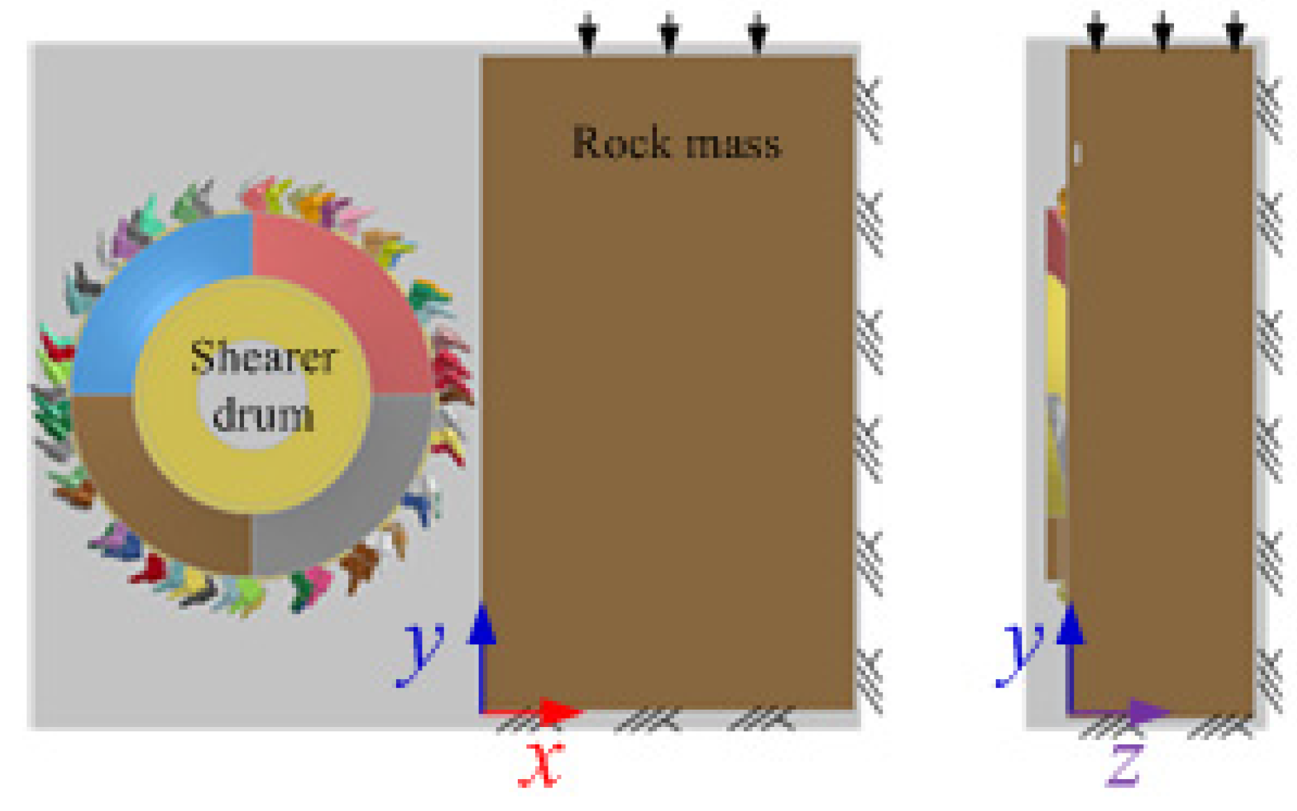
2.1. Boundary Conditions on Rock Mass
2.1.1. Boundary Condition in the Field
Figure 1 shows a common situation during the process of coal mining. Under the action of cutting the head, a goaf area as shown in Figure 1 appears in the complete rock mass. During the mining process, the original stress has been changed and rearranged, and the impact on the mining process cannot be ignored.
Figure 1.
Coal mining diagram.
2.1.2. Boundary Conditions to Be Studied
In order to study the influence of boundary conditions on cutting performance, it is necessary to define each plane of the rock mass. Figure 2 shows the representation of each plane of the rock mass, which is divided into Plane A~Plane F.
Figure 2.
Definition of planes on the rock mass.
The boundary conditions on the rock mass in the study are set as shown in Table 1. Meanwhile, in order to facilitate the observation of the boundary conditions of the rock mass to be studied, Figure 3 presents the boundary conditions to be studied in the paper.
Table 1.
Boundary conditions of the rock mass.
Figure 3.
Boundary conditions to be studied. (a) left and front sides of rock mass are free, and the other sides are constrained; (b) left, front and rear sides are free and the other sides are constrained; (c) left, front, and top sides are free and the other sides are constrained; (d) bottom and right sides of rock mass are constrained and the other sides are free.
When considering confining pressure, the boundary conditions of the rock mass are shown in Figure 4, and uniaxial confining pressure was applied on the top surface of the rock mass. As for the biaxial and triaxial confining pressure, this article will not consider it temporarily. In addition, the values of confining pressure in the text are 0.5 MPa, 1.0 MPa, 1.5 MPa, 2.0 MPa, 2.5 MPa, 3.0 MPa, 5.0 MPa, and 10.0 MPa, respectively.
Figure 4.
Confining pressure on the rock mass.
2.2. Establishment of Hard Rock Cutting Model
2.2.1. Hard Rock Cutting Model
In order to study the rock deformation and cutting force of the shearer drum under the boundary conditions shown in Figure 3 and Figure 4, a numerical model for cutting head cutting of the rock mass is established using finite element software, as shown in Figure 5. Among them, the diameter of the shearer drum is 2.2 m and the width in the z-direction is 0.8 m. The dimensions of the rockwall in the model are 2.0 m in the x-direction, 3.0 m in the y-direction, and 1.2 m in the z-direction. The compressive strength of the rock mass is 120 MPa, the rotational speed of the drum is 6 rad/s, and the traction speed is 150 mm/s. In addition, for the convenience of expression, the following coordinate system is defined, where the origin position of the coordinate system and the x-, y-, and z-axis directions of the coordinate system are shown in the figure.
Figure 5.
Finite element model of the shearer drum and the hard rock mass.
According to the rotary directions of the cutting head in the fields, the cutting process can be divided into two cutting conditions: clockwise cutting and counterclockwise cutting. According to existing literature, the definition of rotary directions is as follows: firstly, stand in the goaf and face the rock wall to be mined; Then, observe the rotary directions of the cutting head. If the cutting head rotates clockwise, then the working condition is named with a clockwise cutting condition; If the cutting head rotates anti-clockwise, the working condition is named with an anti-clockwise cutting condition. According to the definition, Figure 6 shows the schematic diagram of the clockwise and anti-clockwise rotation of the cutting head.
Figure 6.
Definition of rotating directions of cutting head. (a) clockwise cutting direction; (b) counterclockwise cutting direction.
2.2.2. Material Constitutive Model
For the rock materials, the constitutive model revealed the mechanical behavior of rock materials before and after crushing and it is related to the accuracy of numerical simulation results. In the recent literature, the constitutive models of rock material include Mohr Coulomb, Druker Prager, CSCM, etc. Among them, Druker Prager is characterized by fewer and easily identifiable parameters, and it is widely used in the simulation of rock material. The Druker Prager expression is as follows:
where y is the stress deviation, and its expression is shown in Equation (2). q is the equivalent compressive stress, MPa, and its expression is shown in Equation (3). p is the equivalent of Mises stress, MPa, and its expression is shown in Equation (4). N is the deviatoric stress, MPa, and its expression is shown in Equation (5). T3 is the third stress deviator invariant; K is the ratio of yield stress in tensile and compressive tests.
The equivalent plastic strain before and after rock fragmentation is used as the basis for rock fragmentation, and its expression is shown in Equation (6).
where εp is the equivalent plastic strain of rock before rock fragmentation; εf is the equivalent plastic strain of rock after rock fragmentation.
3. Results and Discussion
3.1. Stress Distribution on Rock Mass under Different Confining Pressure
To study the stress distribution in rock mass under different working conditions, a cross-section of the rock mass is selected which is named Section B as shown in Figure 7. The distance between the section and the free surface, Plane A, is 400 mm. Take several equally spaced points along the x- and y-directions on the cross-section, denoted as Ai and Bi, as shown in Figure 7b, to analyze the stress and strain at various positions under different boundary conditions and cutting conditions. The spacing between points in the x-direction is 470 mm, and the spacing between points in the y-direction is 300 mm. The distance from each point Ai in the x-direction to plane A is OAi, and the distance from each point Bi in the y-direction to plane D is PBi. The distances OAi and PBi can be found in Table 2.
Figure 7.
Positions of Section B for studying stress distribution in the rock mass. (a) positions of Section B; (b) sampling points on Section B.
Table 2.
The distance from the sampling point to planes A and D.
Stress distribution on rock mass under confining pressure can be found in Figure 8 and Figure 9. Figure 8 shows the equivalent stress distribution along the y-direction on the rock mass. According to the figure, it can be seen that the equivalent stress close to the region where confining pressure is applied is the highest. As the distance between the sampling point and the region for applying the confining pressure increases, the equivalent stress gradually decreases.
Figure 8.
Stress distributions on the rock mass along the y-direction.
Figure 9.
Stress distributions on the rock mass along the x-direction.
Figure 9 shows the equivalent stress distributions on the rock mass along the x-direction. Compared to the distribution along the y-direction, the differences of equivalent stress in the x-direction are relatively small. When the confining pressure is 5.0 MPa, the differences of equivalent stress in the x-direction were less than 5.0 MPa; When the confining pressure is 10.0 MPa, the differences of equivalent stress in the x-direction were also within 5.0 MPa; When the confining pressure is 15.0 MPa, the differences of equivalent stress increased, but they are still smaller than those differences along the y-direction. According to the comparisons of stress distribution in the x- and y-direction, it could be found that more obvious differences of stress occur in the y-direction.
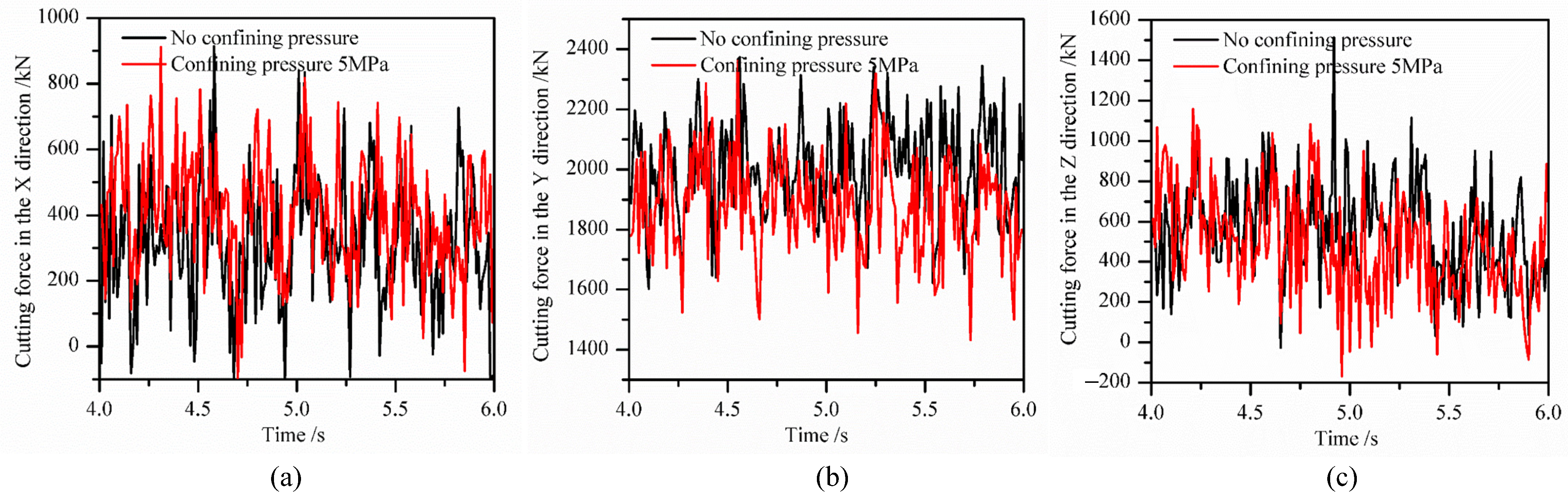
3.2. Influence of the Confining Pressure on the Cutting Performance of Cutting Head
Figure 10 shows the comparisons of cutting forces between no confining pressure and confining pressure of 5.0 MPa. From the respective cutting forces in the x-, y-, and z-directions, whether there is confining pressure or not, the cutting forces in the y-direction are the largest, followed by the cutting forces in the z-direction, and the forces in the x-direction are the smallest. In order to further explore the impact of confining pressure on the cutting force, the mean cutting forces under different confining pressures can be found in Figure 11.
Figure 10.
Rock cutting force on the cutting head in different directions. (a) cutting force in the x-direction; (b) cutting force in the y-direction; (c) cutting force in the z-direction.
Figure 11.
Cutting force in the y-direction under different confining pressures.
According to Figure 11, if there is not any confining pressure on the rock mass and the top side (Plane A) of the rock mass is totally constrained, the cutting force in the y-direction is about 2000 kN. Confining pressure is applied on the top side and if it is 0.5 MPa, the cutting force in the y-direction significantly increases to about 2100 kN. If the confining pressure continues to increase to 1.0 MPa, the cutting force in the y-direction drops a little in comparison with that under the confining pressure of 0.5 MPa. However, the force under the confining pressure is still larger than that without any confining pressure on plane A; When the confining pressure increases to 2.0 MPa, the cutting force in the y-direction is close to that without confining pressure. Afterward, as the confining pressure increases, the decreasing trend of cutting force can be found in the paper. According to Wang et al. [21], under high uniaxial-confining pressure, the high elastic energy stored in rock mass would convert into kinetic energy and rock mass would be broken easily by a smaller cutting force. According to the results, it is helpful to reduce the cutting force on the shearer drum under a certain confining pressure. However, the confining pressure is not always good for improvement of cutting performance. According to Zhu et al. [22], severe rock robustness would happen under higher uniaxial confining pressure, which might lead to disaster underground.
Figure 12 shows the deformation of rock mass in the y-direction under different confining pressures. According to the figure, when the confining pressure on plane A is 0 MPa, there is no deformation of rock mass in the y-direction until cutting happens. After rock cutting happens, deformation of rock mass in the y-direction occurs and increases from 0 mm to 4 mm; When the confining pressure on the plane A is 0.5 MPa, deformation of rock mass occurred in the y-direction even if rock cutting did not happen. Then rock cutting happens and under the influence of cutting force and confining pressure, the deformation of rock mass in the y-direction increased from −0.5 mm to 0 mm and then continued to increase to 5 mm. Therefore, it could be found that the deformation of rock mass in the y-direction firstly decreases under the confining pressure and cutting force, and then increases in reverse.
Figure 12.
Displacements of nodes on the rock mass.
When the confining pressure applied on plane A reached 5.0 MPa, the deformation of rock mass showed with different characteristics. Under the confining pressure, the deformation of rock mass before rock cutting happens (0~4 s in Figure 12) showed the same regularity as those shown under a confining pressure of 0.5 MPa. However, after the 4th second, the regularity of rock deformation in the y-direction seemed to be different, and the deformation in the y-direction began to decrease to 0 mm gradually. Afterward, it started to increase in the opposite direction along the y-direction. When the confining pressure applied on plane A increased to 10.0 MPa, the deformation of rock mass in the y-direction occurred along the opposite direction of the y-direction, whether or not rock cutting happened.
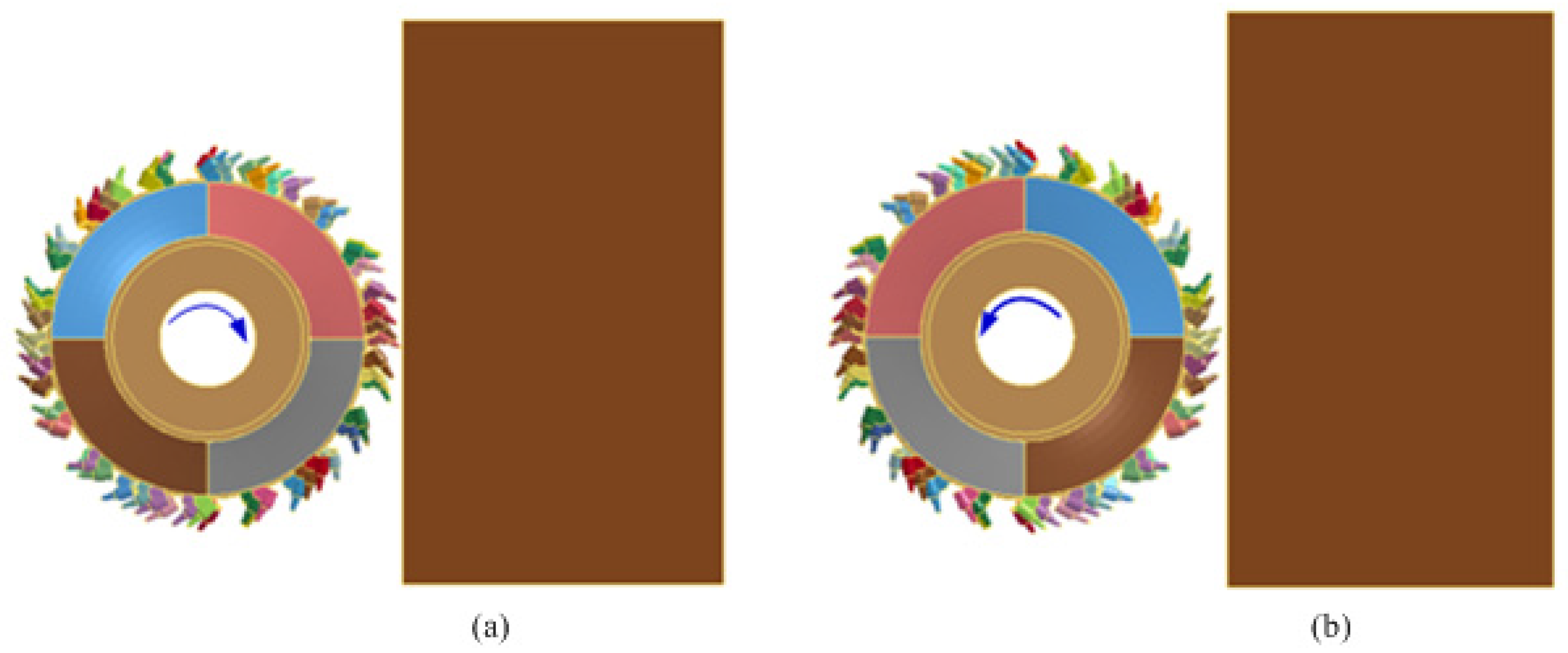
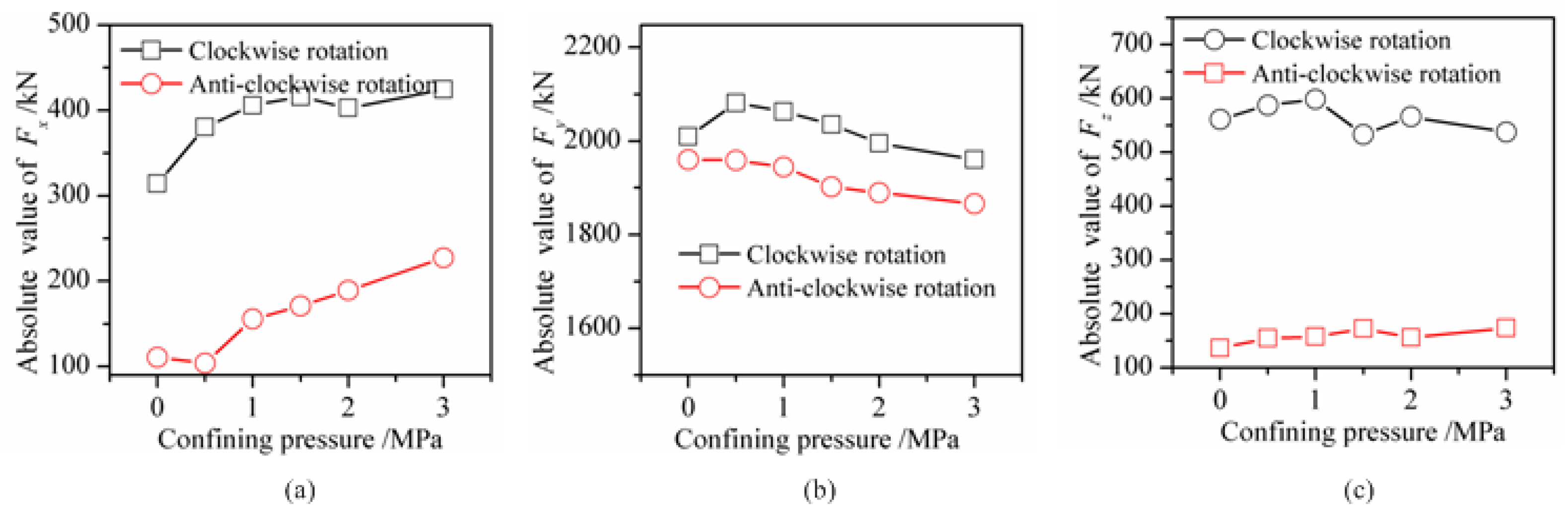
3.3. Influence of the Rotating Directions of Cutting Head on the Working Performance
3.3.1. Cutting Force of Shearer Drum
In order to find the rotation direction of the shearer drum which would be helpful to improve the cutting performance, the cutting force of the shearer drum under clockwise and counterclock rotation is obtained. Figure 13 shows the differences in cutting forces under different rotary directions of the cutting head without confining pressure. According to the figure, if the cutting head rotates anti-clockwise, the cutting forces in the x, y, and z-directions are significantly higher than that works by clockwise rotation. In addition, for the forces in the x-direction, little differences in cutting forces could be found between clockwise or anti-clockwise rotations. For the cutting force in the y-direction, a change in the rotation direction of the cutting head means that the direction of force on the cutting head changes to the opposite direction. As for the cutting forces in the z-direction, they are positive, which means that the direction of they are along the z-direction. This force causes the end plate of the cutting head to press against the rock wall, while during the clockwise cutting of the cutting head, the load in this direction shows a positive and negative alternating pattern, with the end plate sometimes pressing against the rock wall and sometimes far away from the rock wall.
Figure 13.
Cutting force on shearer drum under clockwise and anti-clockwise rock rotating conditions. (a) rock cutting force in the x-direction; (b) rock cutting force in the y-direction; (c) rock cutting force in the z-direction.
Figure 13 shows the comparisons of cutting forces under clockwise and anticlockwise rotary cutting conditions without confining pressure. When there is confining pressure applied on the rock mass like that shown in Figure 3c, the comparisons of cutting forces under clockwise and anti-clockwise rotary cutting conditions are shown in Figure 14. Figure 14 shows the mean cutting forces and the comparisons of them under different confining pressures. According to the figure, it is clear that under different confining pressures, the mean cutting forces in the x-, y-, and z-directions in the anti-clockwise cutting conditions are generally smaller than those in the clockwise cutting conditions. In addition, for the cutting force in the x-direction, with the increasing confining pressure on the rock mass, the mean cutting forces increased as well; For the cutting force in the y-direction, there are some differences in the cutting forces between the clockwise and anti-clockwise cutting conditions. More specifically, if the cutting head rotates clockwise, the variations of cutting forces could be divided into two stages: first increase and then decrease with the increasing confining pressure; if the cutting head rotates anti-clockwise, the cutting forces were always decreasing with increasing of confining pressure.
Figure 14.
Mean rock cutting force on shearer drum under different confining stress. (a) rock cutting force in the x-direction; (b) rock cutting force in the y-direction; (c) rock cutting force in the z-direction.
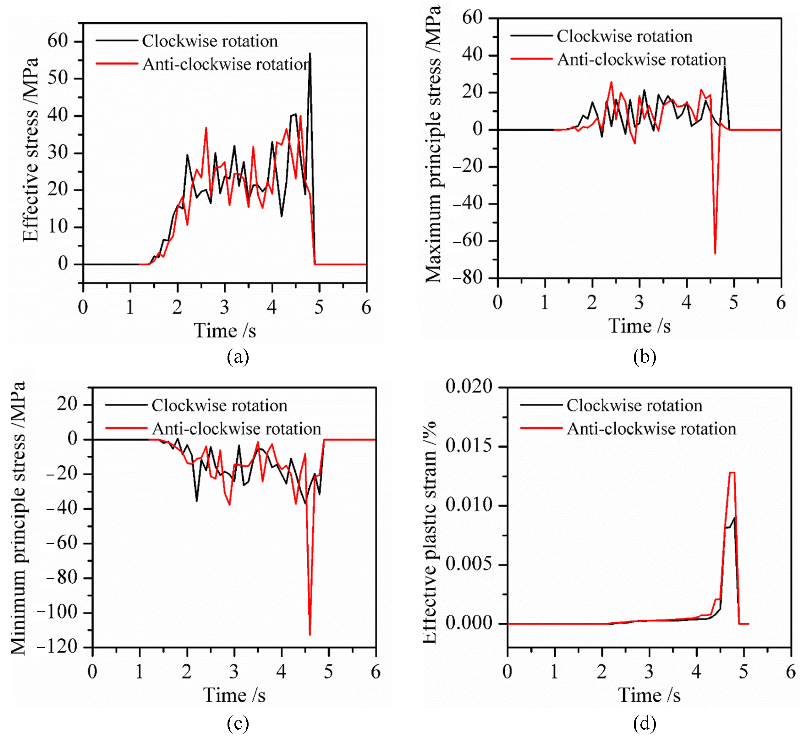
3.3.2. Stress in the Rock Mass
From the macro perspective, the rotating directions of the shearer drum would have an impact on the cutting forces during the cutting process. To explore the reason for the mentioned results, it is essential to conduct research on the stress distributions under different rotating directions of the cutting head.
Figure 15 shows the effective stress, effective plastic strain, maximum principal stress, and minimum principal stress of a rock element, which is named B2 shown in Figure 7b, in conditions of clockwise and counterclockwise cutting conditions. The stress in the rock mass is zero before 1.5 s because of the hollow travel stage of the cutting head and rock cutting didn’t happen before 1.5 s. After 1.5 s, the conical picks on the cutting head began to cut the rock mass, and then, stress occurred and varied in the rock mass. For effective stress, before rock fragmentation, the effective stress is the same under clockwise and counterclockwise conditions. When rock fragmentation occurs, the effective stress under clockwise cutting conditions is significantly higher than that under counterclockwise rotation conditions; For the maximum principal stress, under clockwise cutting conditions, the maximum principal stress at rock failure is positive, while under counterclockwise cutting conditions, the maximum principal stress at rock failure is negative; For the minimum principal stress, under both clockwise and counterclockwise operating conditions, the minimum principal stress is negative, and during counterclockwise cutting, the minimum principal stress during rock fragmentation is higher than that under clockwise conditions; For the effective plastic strain, during the counterclockwise rotation cutting process, the plasticity of the failed element change significantly.
Figure 15.
Stress and strain of rock under clockwise and anti-clockwise cutting directions. (a) effective stress; (b) maximum principal stress; (c) minimum principal stress; (d) effective plastic strain.
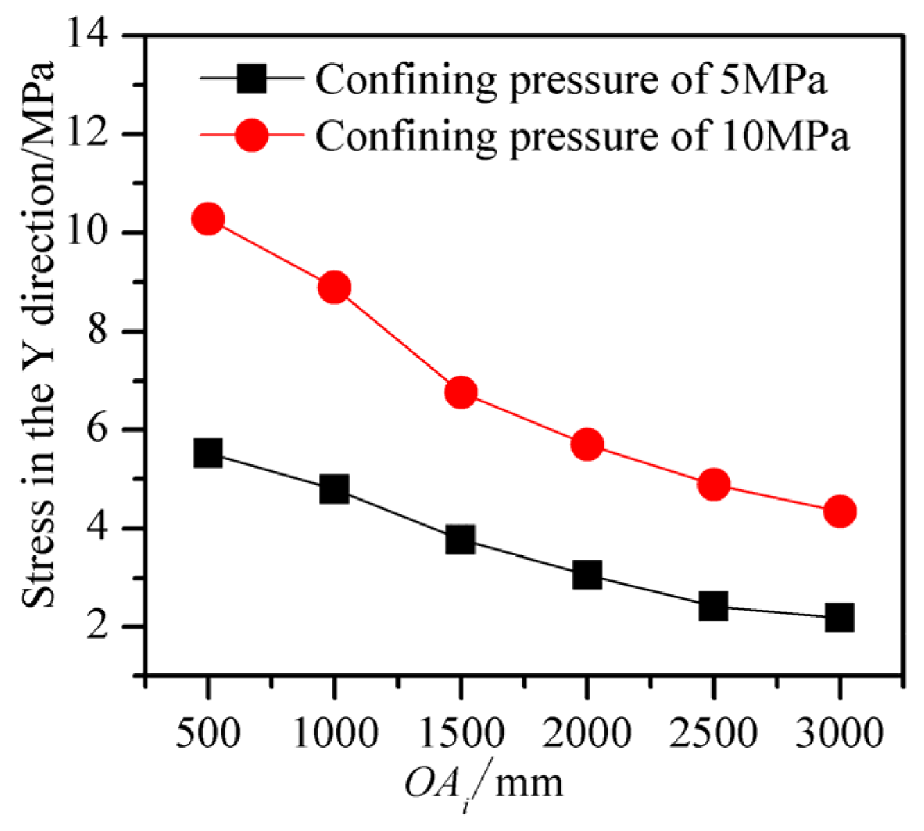
3.4. Influence of Free Surfaces on the Performance of Cutting Head
3.4.1. Free Surface at the Top Side of Rock Mass
According to Wan et al. [18], the free surface on rock mass would be helpful for the reduction of cutting force on the conical pick. However, the reduction of cutting force in conditions with different free surfaces might be different. When the boundary condition of rock mass is like that shown in Figure 3b, and the top side of the rock mass is the free surface, deformations of rock mass in the y- and z-direction are shown in Figure 16. For the deformation of rock mass shown in Figure 16, it could be found that:
Figure 16.
Deformation of rock mass if the top side of rock mass is a free surface. (a) boundary condition of rock mass; (b) deformation in y-direction; (c) deformation in z-direction.
- (1)
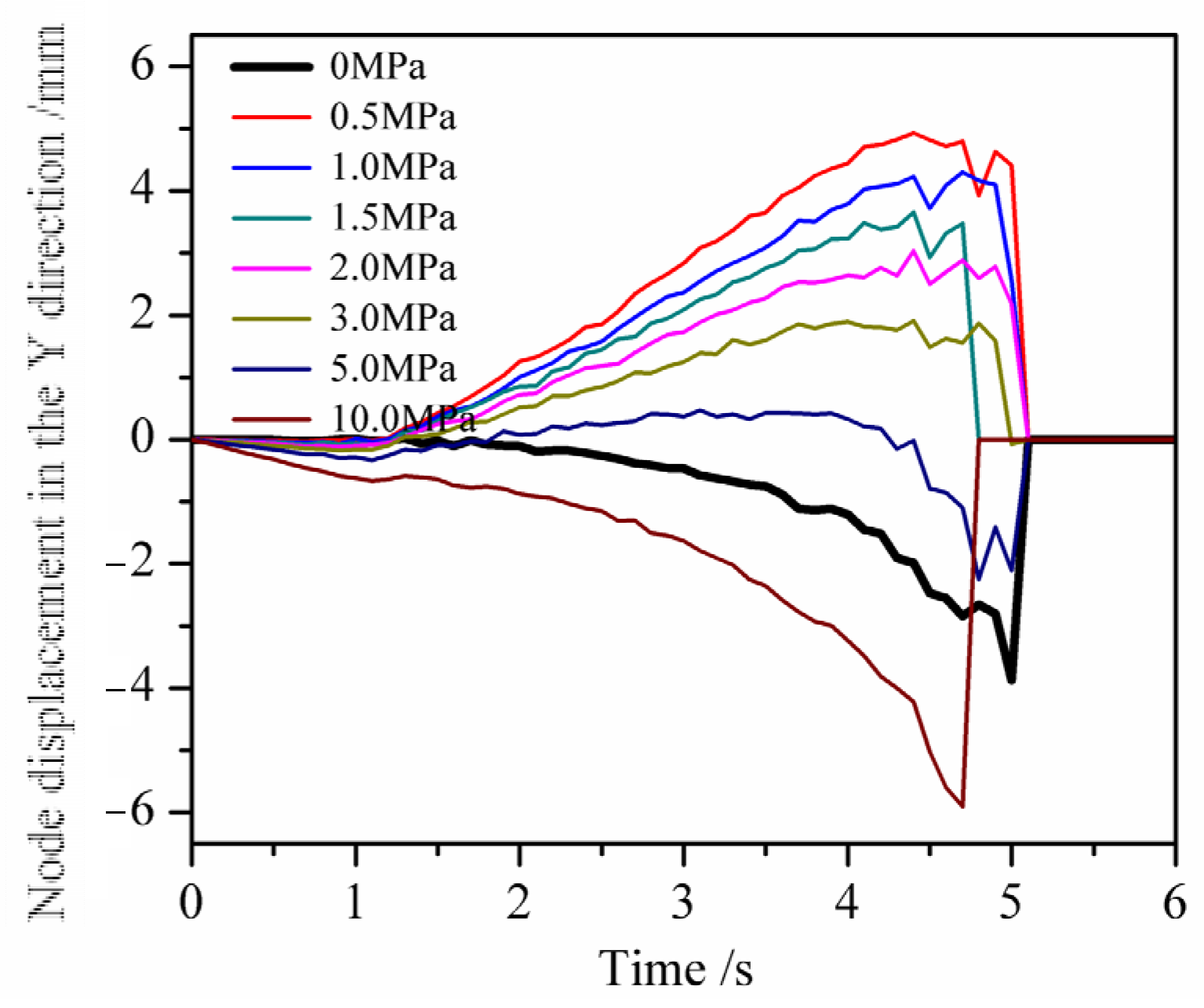
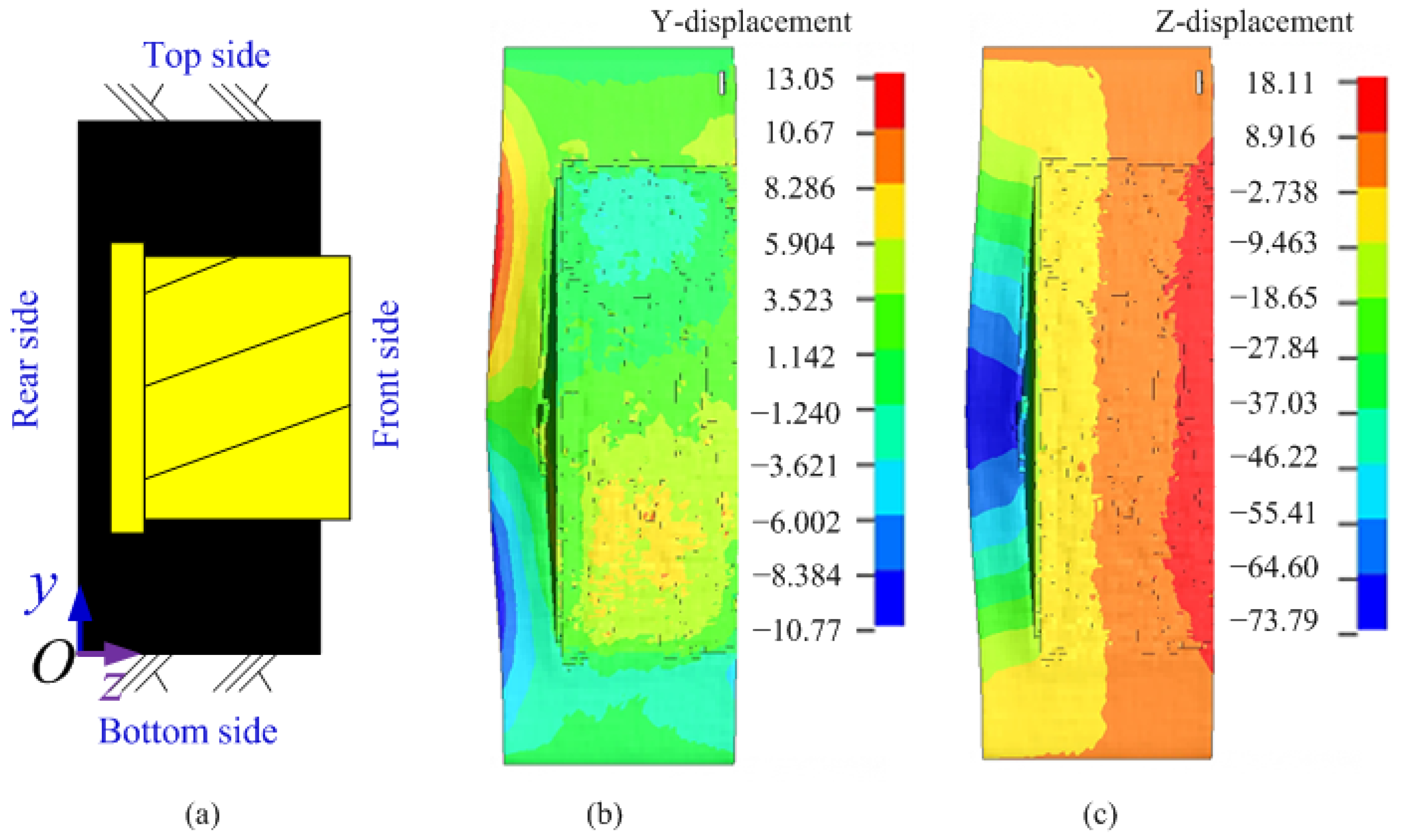
- For the deformation of rock mass in the y-direction, they can be divided into two parts based on sign: in the regions near the top of the rock mass, the displacement of the rock mass is positive; In other areas, the displacement of the rock mass is negative;
- (2)
- For the deformation of rock mass in the z-direction, the displacement of the rock near the free surface is the highest, while it gradually decreases as it moves away from the free surface at other positions;
- (3)
- The deformation of the rock mass near the rear side is negative, while deformation close to the front side is positive. The reasons for this phenomenon are as follows: (1) The rock mass close to the front side is more prone to deformation due to its proximity to the free surface, and the deformation follows the positive direction of the z-axis. (2) During the cutting process, the end plate of the cutting head would compress the rock mass close to the rear side, causing it to move along the opposite direction of the z-axis. However, due to the fully constrained rear side of the rock mass, the element displacements of the rock mass close to the rear side are smaller than the element displacements of the rock mass close to the front side.
Figure 17 shows the comparisons of cutting force in the y-directions if the top side of the rock mass is a free surface. According to the figure, the cutting force in the y-direction under the clockwise cutting condition is higher than that under the counterclockwise cutting condition. In terms of their mean results, the mean cutting force under the clockwise cutting process is about 1961 kN while the mean cutting force under the counterclockwise cutting condition is about 1845 kN. By comparison of the mean cutting force under the counterclockwise cutting condition, the mean cutting force under the clockwise cutting condition increased by about 116 kN, an increase of about 6.28%.
Figure 17.
Rock cutting force in the y-direction if the top side of the rock mass is a free surface.
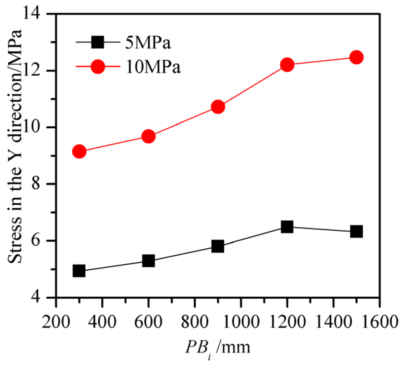
3.4.2. Free Surface at the Rear Side of Rock Mass
When the boundary condition of rock mass is like that shown in Figure 3c, and the rear side of the rock mass is the free surface, deformations of rock mass in the y- and z-directions are shown in Figure 18. For the deformation of rock mass shown in Figure 18, it could be found that the rock mass near the end plate has undergone an obvious deformation in the z-direction. The main reasons for this obvious deformation are the following:
Figure 18.
Deformation of rock mass if the rear side of rock mass is a free surface. (a) boundary condition of rock mass; (b) deformation in y-direction; (c) deformation in z-direction.
- (1)
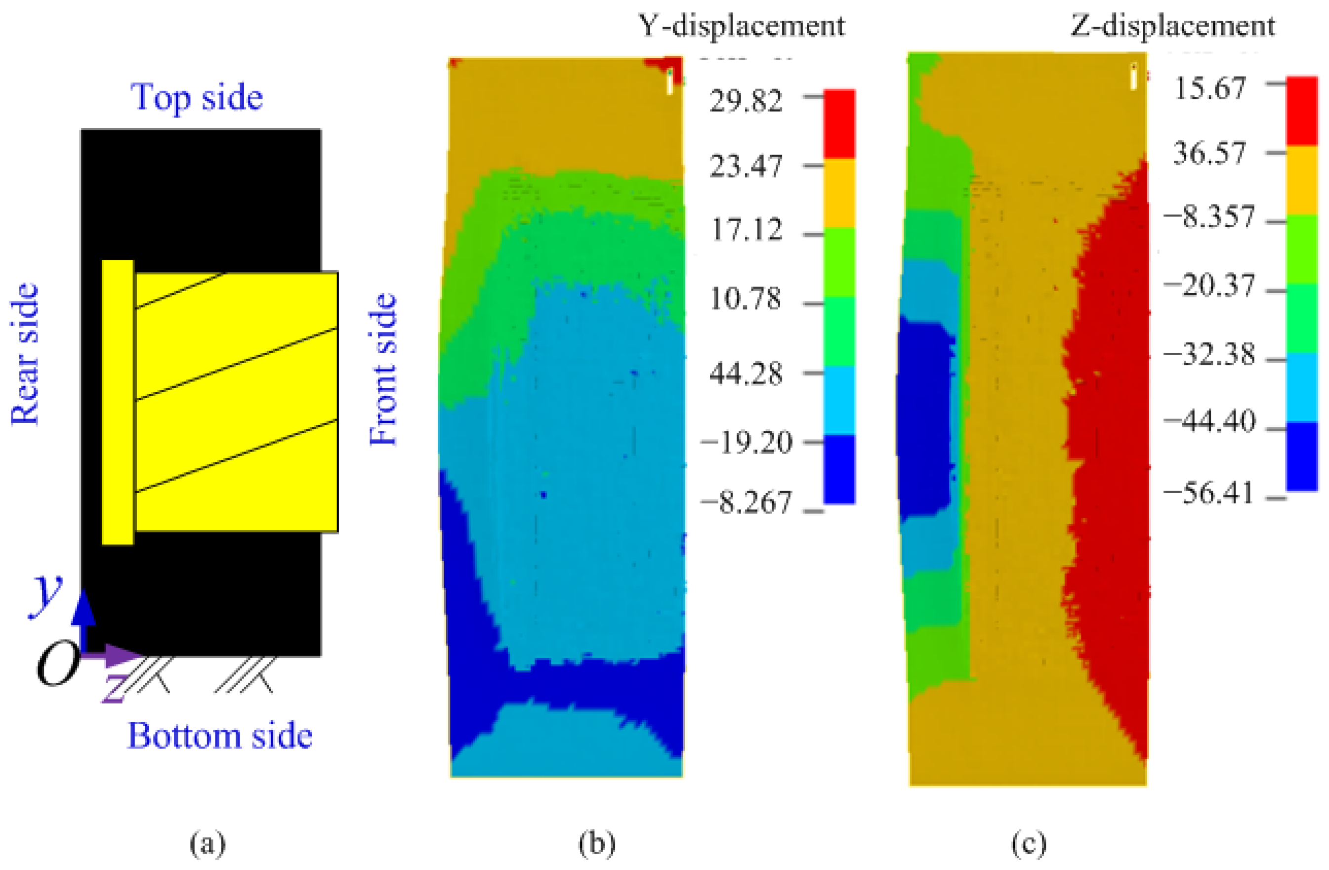
- There is no constraint applied on the rear side of the rock mass, and the rock mass is deformed along the z-direction due to the compression of the cutting forces of conical picks on the end plate of the cutting head during the cutting process;
- (2)
- The top and bottom sides of the rock mass are fully constrained, which means that even if some cutting forces from conical pick are applied on those regions, no displacement occurs. Therefore, the bulging deformation of the rock mass at the rear side of the rock mass would appear.
According to Tiryaki [17], the conical picks on the end plate of the shearer drum suffer severe wear during the cutting process. When there is a free surface close to the end plate of the shearer drum as shown in Figure 18, larger deformation on rock mass close to the end plate of the shearer occurs, and the interval between rock mass and the end plate of the shearer drum increases, which would be helpful to reduce the cutting force on shearer drum.
When there is a free surface on the rear side of the rock mass, the cutting force on the shearer drum during the clockwise and counterclockwise rotation is shown in Figure 19. According to the figure, the cutting forces were similar under the different directions of rotating cutting. From the perspective of mean cutting forces, it was approximately 1870 kN in the clockwise cutting condition while in the counterclockwise cutting condition, the mean cutting force is approximately 1822 kN. Compared to the mean cutting force under the anti-clockwise cutting condition, the mean cutting force under clockwise cutting conditions increased by about 48 kN, an increase of about 2.63%. Therefore, the mean cutting force under clockwise cutting conditions is much larger than that under counterclockwise cutting conditions.
Figure 19.
Rock cutting force in the y-direction if the rear side of the rock mass is a free surface.
3.4.3. Free Surfaces at the Top and Rear Side of Rock Mass
When free surfaces appear on both the top and rear side of the rock mass, as shown in Figure 3d, the deformation of the rock mass during the clockwise cutting process of the drum is shown in Figure 20. Compared to the boundary conditions shown in Figure 16 and Figure 18, the deformation of the rock mass in the y-positive direction increases in Figure 20, which means that the squeezing force between the top rock mass and the drum is reduced in this working condition, helping reduce the cutting force of the drum; However, the decreased deformation of the rock mass in the z positive direction occurs in the Figure 20 and it means that little interval between the end plate of drum and rock mass, which might add extra friction on the end plate of drum. Therefore, the cutting force on the shearer drum might increase or decrease when compared to the working conditions in Figure 16 and Figure 18, which will be studied in the following section.
Figure 20.
Deformation of rock mass if the top and rear side of rock mass are free surfaces. (a) boundary condition of rock mass; (b) deformation in y-direction; (c) deformation in z-direction.
Figure 21 shows the forces of the cutting head under the clockwise and anti-clockwise cutting directions. According to the figure, it can be found that the influence of the rotation direction of the cutting head on the cutting forces is not significantly different; As for the mean cutting force, the mean cutting force in the clockwise cutting direction is about 1994 kN; When the cutting head rotates anti-clockwise, the mean cutting force of the cutting head is about 1952 kN. Compared to the forces in the anti-clockwise rotation, the forces in the clockwise cutting direction increased by 42 kN, an increase of approximately 2.15%.
Figure 21.
Rock cutting force in the y-direction if the top and rear side of the rock mass are free surfaces.
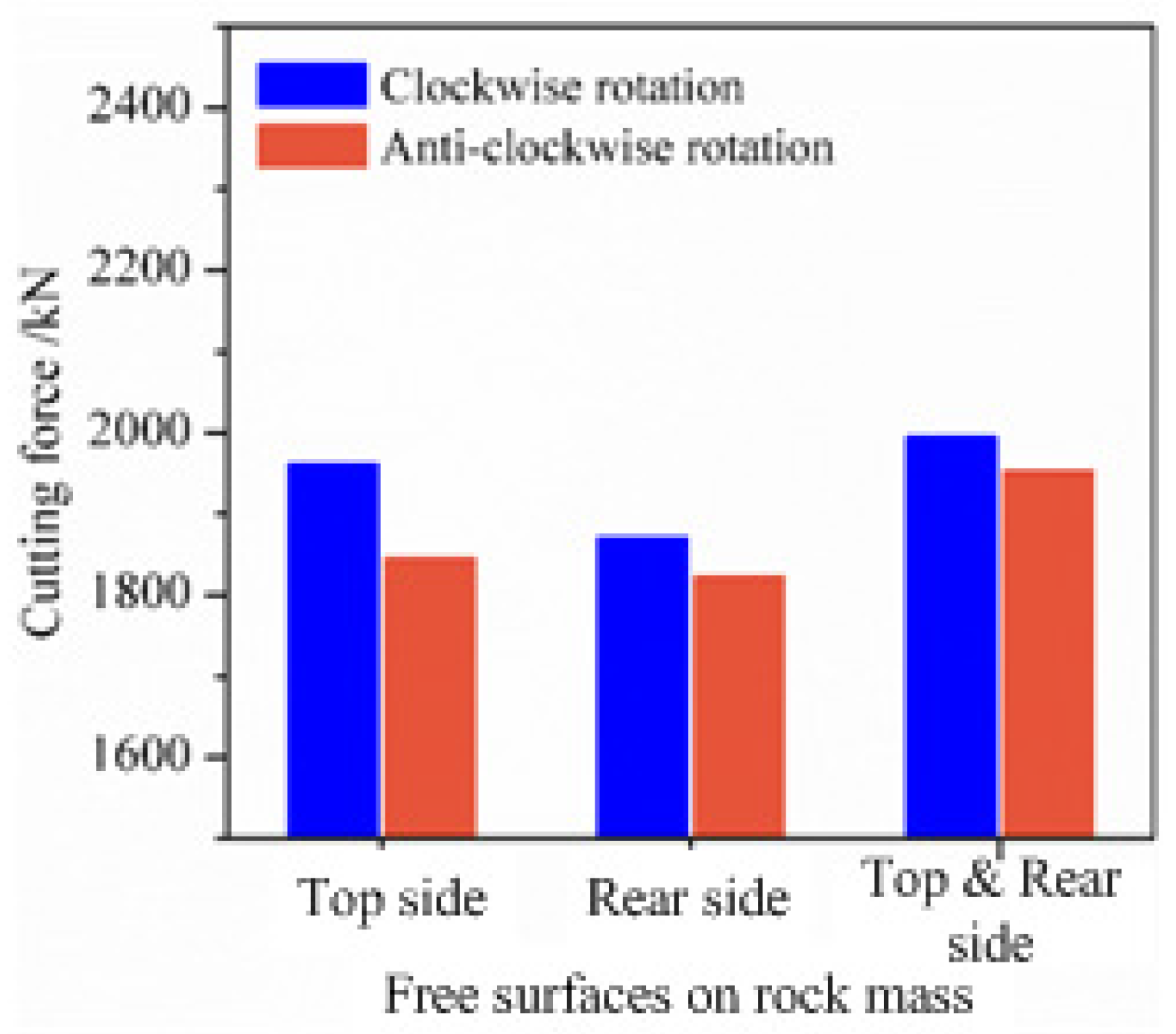
3.4.4. Comparisons of Cutting Force in Conditions of Different Free Surfaces on Rock Mass
According to Figure 17, Figure 19 and Figure 21, the mean cutting force of the shearer drum under different boundary conditions could be obtained in Figure 22. Figure 22 shows the cutting forces in the y-direction under different constraints on rock mass and different rotating directions of the cutting head.
Figure 22.
Comparisons of mean cutting forces between different boundary conditions.
According to Figure 22, the minimum mean cutting force of the shearer drum occurs in the boundary condition as shown in Figure 18a where the rear side of the rock mass is free and the cutting force in this boundary condition is about 1870 and 1822 kN. Significantly, the number of free surfaces of rock mass in Figure 20a is four, larger than that in Figure 18a, but the mean cutting force in Figure 20a is 1994 and 1953 kN, still larger than that in Figure 18a. Therefore, the amount of free surfaces on rock mass is not the more the better and the best boundary condition to improve the cutting performance is to create a free surface on rock mass that is close to the end plate of the shearer drum as shown in Figure 3c. According to Fenn et al. [19,20], saw blade and water jet assistant technology provide the possibility for excavation of free surface on the rock mass. Therefore, it is applicable to reduce the cutting force on the shearer drum by improving the boundary condition of the rock mass.
4. Conclusions
- (1)
- When the confining pressure on the rock mass is small, the mean cutting force of the cutting head is greater than that without confining pressure; The increase of confining pressure on the rock mass would be helpful to reduce the mean cutting force on cutting head and improve the cutting performance.
- (2)
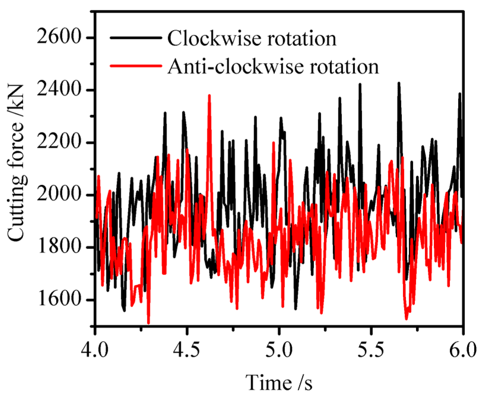
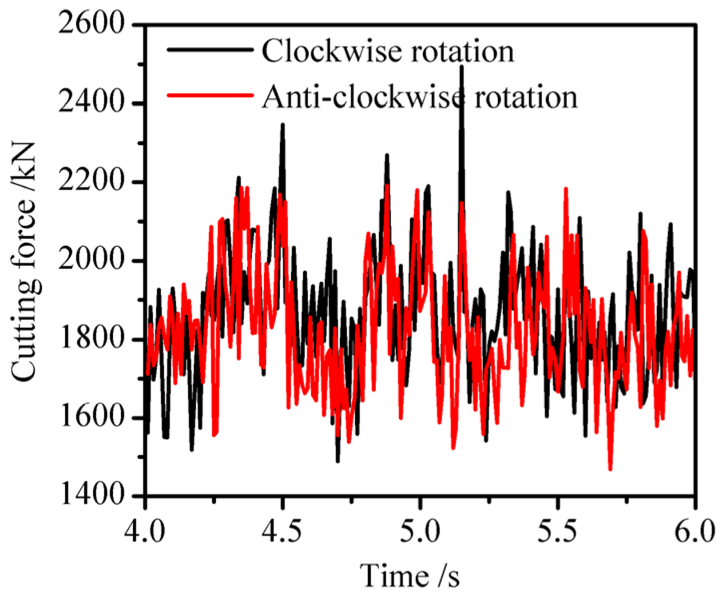
- During the process of rock cutting, the rotating direction of the shearer drum have influence on the cutting performance of shearer drum. When the cutting head rotates in the clockwise direction, the cutting force is greater than that in the anti-clockwise cutting direction of cutting head.
- (3)
- The cutting force on the shearer drum could be influenced by the unconstrained surface on rock mass. The unconstrained surfaces on rock mass are helpful to reduce the cutting force on the shearer drum. Among the different boundary conditions, the best boundary condition to improve the cutting performance is to create a free surface on rock mass that is close to the end plate of the shearer drum.
This article proposes a method that helps improve the cutting performance of the drum by increasing the free surface of the rock mass to reduce the cutting resistance. At present, there are some technologies for free surface excavation on rock mass, such as combined rock breaking with saw blades and water jet assistant rock breaking method. However, whether the cost of free surface excavation could be covered by the benefit of performance improvement of the shearer drum and which technology of free surface excavation could get the job done would be topics that need further research in the future.
Author Contributions
Conceptualization, L.W. and K.G.; methodology, K.G.; software, W.X.; validation, W.X. and K.J.; formal analysis, W.X.; writing—original draft preparation, W.X.; writing—review and editing, W.X., K.J., Y.B., M.X. and S.M.; project administration, L.W.; funding acquisition, K.G. All authors have read and agreed to the published version of the manuscript.
Funding
This research was funded by the National Natural Science Foundation of China, grant number 52174146, and Special Project for Science and Technology Innovation of China Coal Technology and Engineering Group, 2023-TD-ZD003-006.
Institutional Review Board Statement
Not applicable.
Informed Consent Statement
Not applicable.
Data Availability Statement
The data presented in this study are available on request from the corresponding author. The data are not publicly available due to privacy.
Conflicts of Interest
Author Weipeng Xu was employed by the company China Coal Technology & Engineering Group Shanghai Co., Ltd. The remaining authors declare that the research was conducted in the absence of any commercial or financial relationships that could be construed as a potential conflict of interest.
References
- Munene, E.K.; Zhang, J.M.; Kasomo, R.M.; Mauti, D.; Mwangangi, J. A review of the influence of blast fragmentation on downstream processing of metal ores. Miner. Eng. 2022, 186, 107743. [Google Scholar]
- Eades, R.; Perry, K. Understanding the connection between blasting and highwall stability. Int. J. Min. Sci. Technol. 2019, 29, 99–103. [Google Scholar] [CrossRef]
- Abd Elwahab, A.; Topal, E.; Jang, H. Review of machine learning application in mine blasting. Arab. J. Geosci. 2023, 16, 133. [Google Scholar] [CrossRef]
- Roy, M.P.; Singh, P.K.; Sarim, M.; Shekhawat, L.S. Blast design and vibration control at an underground metal mine for the safety of surface structures. Int. J. Rock Mech. Min. 2016, 83, 107–115. [Google Scholar] [CrossRef]
- Wu, Y.; Mu, C.; Zong, Q.; Wu, J.; Zhou, H. Study on blasting vibration control of brick-concrete structure under subway tunnel. Appl. Sci. 2022, 12, 10960. [Google Scholar] [CrossRef]
- Ahmadi, S.; Moosazadeh, S.; Hajihassani, M.; Moomivand, H.; Rajaei, M.M. Reliability, availability and maintainability analysis of the conveyor system in mechanized tunneling. Measurement 2019, 145, 756–764. [Google Scholar] [CrossRef]
- Hoseinie, S.H.; Ataei, M.; Khalokakaie, R.; Ghodrati, B.; Kumar, U. Reliability analysis of drum shearer machine at mechanized longwall mines. J. Qual. Maint. Eng. 2012, 18, 98–119. [Google Scholar] [CrossRef]
- Ordin, A.A.; Okol’nishnikov, V.V.; Rudometov, S.V.; Metel’kov, A.A. Evaluation of drum shearer capacity in coal seam with variable geomechanical and geotechnical characteristics. J. Min. Sci. 2019, 55, 57–65. [Google Scholar] [CrossRef]
- Bredthauer, R.O. Strength characteristics of rock samples under hydrostatic pressure. J. Fluid Eng. 1957, 79, 695–706. [Google Scholar] [CrossRef]
- Lee, H.; Jeon, S. An experimental and numerical study of fracture coalescence in pre-cracked specimens under uniaxial compression. Int. J. Solids Struct. 2011, 48, 979–999. [Google Scholar] [CrossRef]
- Kumari, W.G.P.; Ranjith, P.G.; Perera, M.S.A.; Shao, S.; Chen, B.K.; Lashin, A.; Arifi, N.A.; Rathnaweera, T.D. Mechanical behaviour of Australian Strathbogie granite under in-situ stress and temperature conditions: An application to geothermal energy extraction. Geothermics 2017, 65, 44–59. [Google Scholar] [CrossRef]
- Shahverdiloo, M.R.; Zare, S. Experimental study of normalized confining pressure effect on Young’s modulus in different rock types. Arab. J. Geosci. 2023, 16, 55. [Google Scholar] [CrossRef]
- Li, Y.L.; Peng, J.M.; Zhang, P.Y.; Huang, C.Y. Hard rock fragmentation in percussion drilling considering confining pressure: Insights from an experimental study. Int. J. Rock Mech. Min. 2021, 148, 104961. [Google Scholar] [CrossRef]
- Qiao, S.; Wu, Y.; Zhu, Z.; Qing, L.; Huang, Z.; Ning, Q. Effects of confining pressure and cutting sequence on the cobalt-rich crust cutting mechanism by using conical picks in ocean environments. Ocean Eng. 2022, 263, 112348. [Google Scholar] [CrossRef]
- Qiao, S.; Wu, Y.; Zhu, Z.; Zhang, Z.; Lu, L. Numerical Investigation of Rock Cutting Modes with Conical Picks under Different Confining Pressures and Cutting Spaces. Arab. J. Sci. Eng. 2021, 47, 4559–4569. [Google Scholar] [CrossRef]
- Liu, W.; Deng, H.; Zhu, X.; Li, R.; He, C. Experimental study of the rock cutting mechanism with pdc cutter under confining pressure condition. Rock Mech. Rock Eng. 2023, 56, 7377–7396. [Google Scholar] [CrossRef]
- Tiryaki, B. In situ studies on service life and pick consumption characteristics of shearer drums. J. S. Afr. Inst. Min. Metall. 2004, 104, 107–121. [Google Scholar]
- Wan, L.; Jiang, K.; Gao, K.; Zeng, Q.; Zhang, X. Research of response difference on coal cutting load under different cutting parameters. Stroj. Vestn.-J. Mech. E 2019, 65, 420–429. [Google Scholar] [CrossRef]
- Xu, F.T.; Lu, J.J.; Zhou, H.; Xiao, J.C.; Gao, Y. Failure characteristics of rock sample during penetration tests with the assistance of different free surface combinations. Lithosphere 2022, 2021, 6216548. [Google Scholar] [CrossRef]
- Fenn, O. The use of water jets to assist free-rolling cutters in the excavation of hard rock. Tunn. Undergr. Space Technol. 1989, 4, 409–417. [Google Scholar] [CrossRef]
- Wang, S.F.; Li, X.B.; Du, K.; Wang, S. Experimental investigation of hard rock fragmentation using a conical pick on true triaxial test apparatus. Tunn. Undergr. Space Technol. 2018, 79, 210–223. [Google Scholar] [CrossRef]
- Zhu, G.-A.; Dou, L.-M.; Wang, C.-B.; Ding, Z.-W.; Feng, Z.-J.; Xue, F. Experimental study of rock burst in coal samples under overstress and true-triaxial unloading through passive velocity tomography. Saf. Sci. 2019, 117, 388–403. [Google Scholar] [CrossRef]
Disclaimer/Publisher’s Note: The statements, opinions and data contained in all publications are solely those of the individual author(s) and contributor(s) and not of MDPI and/or the editor(s). MDPI and/or the editor(s) disclaim responsibility for any injury to people or property resulting from any ideas, methods, instructions or products referred to in the content. |
© 2023 by the authors. Licensee MDPI, Basel, Switzerland. This article is an open access article distributed under the terms and conditions of the Creative Commons Attribution (CC BY) license (https://creativecommons.org/licenses/by/4.0/).