1. Introduction
Strokes and spinal cord injuries (SCIs) are primary causes of long-term difficulties in walking, which can significantly impact a person’s mental, emotional, and social well-being [
1]. After experiencing a stroke, approximately 66% of survivors encounter challenges with walking right away. Even six months later, more than 30% continue to require assistance for walking [
2]. These walking disabilities impose limitations that increase the risk of developing other chronic health conditions, including osteoporosis, cancer, cardiovascular diseases, and diabetes. Furthermore, individuals with walking limitations often face restricted activities at home and within their communities, leading to social isolation and confinement [
3]. Consequently, gait rehabilitation programs are typically recommended for stroke victims and SCI patients to prevent additional health issues and facilitate the recovery of their walking abilities.
The most common types of gait rehabilitation used by therapists include treadmill exercise and traditional overground gait training. Overground gait training, which is a commonly used approach, involves a physical therapist observing and adjusting an individual’s walking on a regular floor surface [
4,
5]. It encompasses practice on various terrains and includes specific exercises for gait improvement. This approach is used across diverse healthcare settings, highlighting its functional role in physical therapist education and practice. An emerging approach to gait rehabilitation, utilizing a treadmill with body weight support (BWS), holds significant promise in the field. This method offers an avenue for severely affected patients to align with contemporary principles of motor learning, emphasizing a task-specific approach. This approach involves the assistance of two therapists who facilitate limb placement and oversee trunk movements [
6]. When compared to conventional overground walking, patients exhibit increased symmetry, reduced spasticity, and enhanced efficiency during treadmill-based walking with BWS [
4,
7].
Advancements in technology have led to the development of orthotic devices prioritizing biomechanical alignment in lower extremities. Robot-assisted gait training, coupled with physical therapy, increases the likelihood of stroke survivors achieving independent gait [
8]. Various organizations are designing exoskeletal devices, with the Lokomat [
9] and GEAR [
10] being prominent rehabilitation tools using a body-weight-support treadmill system to enhance movement in weakened limbs. While proven effective, these exoskeletal devices often still incorporate body-weight-support harnesses, causing challenges and discomfort for therapists and patients [
11,
12]. Refer to
Table 1 for examples of harness-free exoskeletal devices.
These systems have innovatively eliminated the conventional harnessed approach employed in traditional gait rehabilitation. Both the EKSO GT and HANK represent battery-operated suits with integrated bionic components and backpack systems, orchestrating precise control over a patient’s gait. The ANdROS system comprises a pelvic brace, an unactuated leg brace, and actuated leg brace, focusing on gait corrections for a single leg. In contrast, the device developed by Luangwa University is affixed to a support structure, securing the patient in an upright position. However, the process of correctly positioning the patient within these devices poses challenges, particularly given the often-limited motor skills of individuals with disabilities. Addressing these difficulties is crucial for optimizing the effectiveness of these advanced gait rehabilitation systems.
In response to this challenge, a robot-assisted rehabilitation device has been developed at the University of Texas at Tyler, namely the robotic walking training device (RWTD), which incorporates an innovative solution [
19,
20]. The RWTD design integrates a tilt table (adjustable back supports) into the exoskeletal walking device, obviating the need for body-support harnesses. This tilt table serves the dual purpose of easily positioning the patient in a supine orientation and subsequently adjusting to the optimal angle for rehabilitation. As the patient’s orientation transitions closer to a fully upright stance, a gradual redistribution of weight occurs, with the greater load being borne by the lower extremities. The rehabilitation process commences with the RWTD in the supine position, where the patient’s lower extremities bear the least amount of weight, and systematically progresses by tilting the patient to apply incrementally more weight to the lower limbs as rehabilitation advances.
This marks the fifth generation of the project, with four previous iterations leading up to the current device. The primary objective of this latest generation is to enhance the device’s capabilities by increasing the maximum lift angle to 90 degrees. This enhancement will enable patients to utilize the RWTD in an upright vertical position, allowing for a more versatile and precise simulation of the patient’s walking gait. The current RTWD is secured to an off-the-shelf scissor lift that is able to tilt the patient up to 45 degrees.
In this work, the collective aim was to create a highly functional, patient-centric RWTD that not only advances the field of medical equipment design but also empowers patients on their path to recovery. The design choice for optimization in future designs features a rotational lift table, powered by four motors, to elevate the patient and enable the placement of the RWTD underneath.
2. Design and Methods
The RWTD was originally designed to assist with spinal injury and stroke recovery. A mechanism that supports the RWTD and can reposition a patient’s long axis (PLA) from a supine position to a standing (vertical) position while attached to the RWTD is desired. The targeted patient’s height ranges from 4.5 to 6.3 feet with a weight not exceeding 300 pounds. The original RWTD has been modified with an off-the-shelf (OTS) lift and tilt table to mount the entire system. This configuration, however, imposes constraints with a maximum tilt angle capped at 60 degrees. In this work, many efforts have been made to increase the RWTD’s lifting capabilities from 0 degrees (i.e., a supine position) to 90 degrees (i.e., a standing position) during operation.
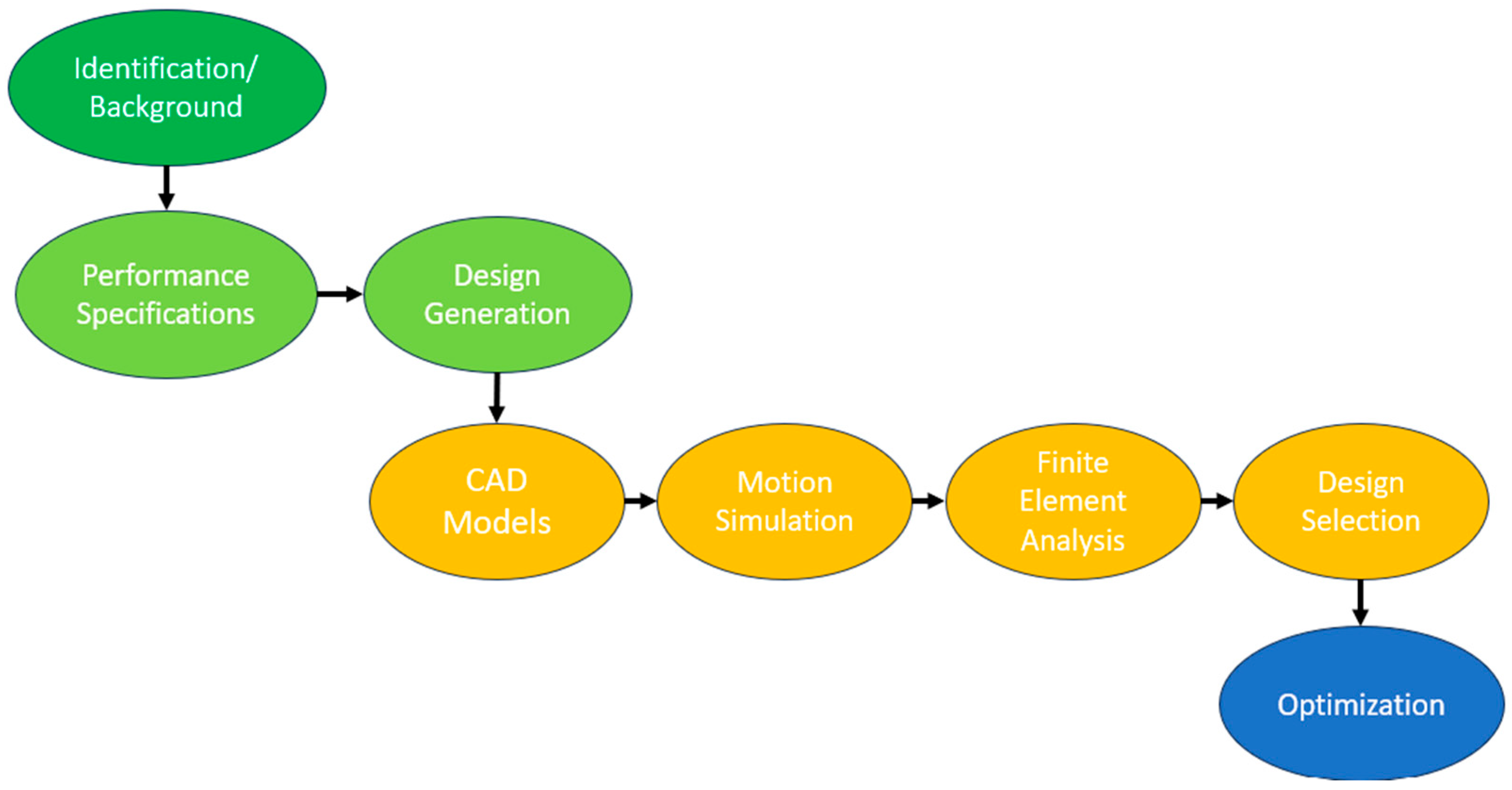
The design and simulation process are summarized in
Figure 1, where 3 different lift mechanisms were modeled to evaluate each design in SolidWorks, commercial computer-aided design (CAD) software. Data were collected on the dynamic motion of each CAD model using SolidWorks motion, followed by finite element analysis, using ANSYS static structural 2023 R2, to collect structural data for each design. The culmination of this process involved the selection of a design solution through the design section matrix methodology to determine the best alternative among the three design concepts.
Future efforts will be directed toward further optimizing the chosen design, with a particular emphasis on enhancing the functionality and safety of the RWTD lift mechanism. This optimization phase aims to refine the selected design, ensuring it not only meets but surpasses performance expectations, contributing to the continued advancement of RWTD technology.
2.1. Engineering Design Process
The standard five-step approach commonly employed in problem-solving is applicable to design problems as well. Design problems are generally defined more vaguely and have multiple correct solutions, due to the design process not being linear. Consequently, the design process often involves retracting steps and repeating iterations. Solving a design problem is a dynamic process, and the ultimate solution may encounter unexpected challenges and undergo changes during its development.
The five steps utilized in the engineering design process are as follows [
21]:
To commence the resolution of a design problem, it is crucial to have a clear unambiguous definition of the issue at hand. Design problems often begin with vague and abstract concepts in the mind of the designer. Crafting a precise definition for a design problem presents greater challenges compared to defining an analytical problem. As the design process unfolds, the problem’s definition may evolve through a series of steps or processes, as a more comprehensive understanding of the issue is developed.
- 2.
Gather background information and data.
To proceed effectively in the design process, it is essential to gather all available information that pertains to the problem. Novice designers often overlook this step and jump straight into generating alternative solutions. The process of gathering pertinent information can lead to the discovery of facts that may prompt a redefinition of the problem.
- 3.
Generate numerous potential solutions.
In the design process, creativity involves going beyond set rules and theories to develop innovative solutions. This entails dissecting existing solutions, identifying weaknesses, and merging fresh ideas and techniques to formulate unique answers. Collaboration and brainstorming foster the generation of diverse solutions in the engineering design process.
- 4.
Analyze and choose the most suitable solution.
After generating alternative solutions in the design process, the next step involves analyzing these solutions to determine the most suitable one for implementation. Analysis entails evaluating proposed designs using technical knowledge to make an informed choice. This stage becomes more comprehensive in advanced engineering courses. Considering the outcomes of design analysis is a subjective process that benefits from the input of experienced individuals. This section presents a systematic approach to evaluating alternative designs and aiding decision-making processes.
- 5.
Test and implement the selected solution.
The last stage of the design process is implementation, encompassing the testing, construction, and production of the design problem’s solution. Various implementation methods like prototyping and concurrent engineering should be considered, alongside specific activities like documenting the design solution and seeking patents.
2.2. Structural Analysis Using ANSYS Finite Element Analysis
In the realm of engineering design, the utilization of finite element analysis (FEA) has proven instrumental in evaluating stress distribution and deflection within a CAD assembly. FEA is especially utilized in the pre-prototyping phase encompassing multiple design iterations. FEA serves as a powerful numerical technique for simulating complex mechanical behavior by discretizing a given structure into finite elements. This methodology enables the prediction of stress concentration and deflection patterns under various loading conditions offering insight into the structural integrity and performance of designs prior to the resource-intensive prototyping stage. FEA aids in efficient decision-making by swiftly evaluating multiple designs, enhancing the design process. For this project study, ANSYS Static Structural 2023 R2 will compute the finite element analysis.
2.2.1. FEA Model Description
The objective of the FEA is to identify worst-case stresses and deflections in each design by evaluating multiple angles throughout the device’s motion. To simplify the model, the RWTD and patient are represented as point loads with the correct moment of inertia. Revolute joints mimic the actual pivots and rotations of a pin for replicating the linkages’ motion, while motor-driven joints are portrayed as fixed joints. Fixed support constraints are applied to the wheels of each device to firmly anchor the model to the ground.
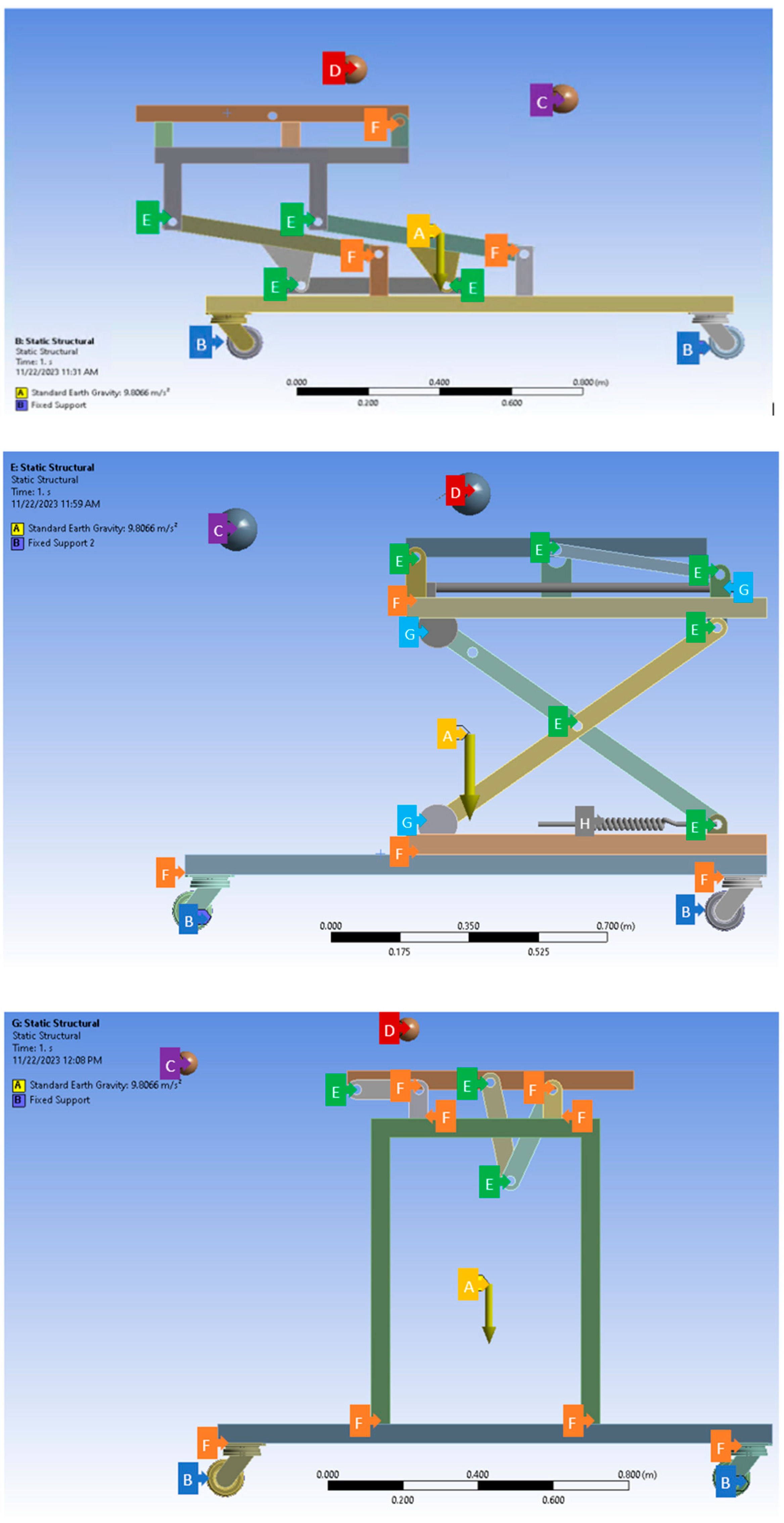
Figure 2 outlines the constraints used to evaluate each of the 3 design concepts. These constraints are used as the applied loading and boundary conditions in the FEA, including gravitational acceleration, fixed supports, point loads, and simulated joints, which were used as the applied loading and boundary conditions in the FEA.
Figure 2.
FEA constraints. Top: constraints for Concept 1—rotational lift; middle: constraints for Concept 2—scissor lift; bottom: constraints for Concept 3—double pivot lift. FEA constraint letters and colorization are listed below:
Figure 2.
FEA constraints. Top: constraints for Concept 1—rotational lift; middle: constraints for Concept 2—scissor lift; bottom: constraints for Concept 3—double pivot lift. FEA constraint letters and colorization are listed below:
| Letter | Color | Description |
| A | Yellow | Gravity acceleration -y direction |
| B | Blue | Fixed supports on outer wheels |
| C | Purple | Point load RWTD limbs |
| D | Red | Patient point load |
| E | Green | Revolute joints to simulate pin connections |
| F | Orange | Fixed joints used to simulate connection and motor joints |
| G | Light Blue | Translation joints |
| H | Grey | Spring with spring constants of a linear actuator |
2.2.2. FEA Model Validation
FEA model validation is summarized in
Table 2. Mesh analysis, a pivotal facet of FEA, profoundly influences the precision and reliability of its outcomes. FEA relies on discretizing complex structures into finite elements interconnected at nodes. The models use a mixture of tetrahedral and hexahedron quadratic elements throughout the analysis. Mesh quality, measured through aspects such as aspect ratio, Jacobian ratio across Gauss points, and overall element quality, is paramount for accurate stress and strain visualization. For the aspect ratio, an ideal element will have a value of 1 in all these aspects, but it cannot always be maintained. In general, the aspect ratios are maintained in between 1 to 5 for a good-quality mesh in FEA [
22]. The Jacobian ratio measures the deviation of an element’s shape and a value close to or equal to 1.0 is desired [
23]. The element quality (EQ) describes area or volume over sum of square of edge lengths. EQ measures how far elements are from being perfect [
24].
The mesh quality, be it fine or coarse, balances computational resources and precision. Proper meshing ensures solution convergence and enables stress and strain visualization. It helps identify stress concentrations and accounts for local effects. Mesh analysis is vital for model validation, aligning FEA simulations with real-world observations, and thus enhancing scientific rigor and reliability in FEA applications.
Static structural modulus in ANSYS Workbench provides a mesh convergence tool. This tool uses the calculated stresses across all the node points to find the areas of highest stress. The software then reduces the meshing in the areas around these elements of high stress in an iterative process until the stresses have converged to a required percentage.
Figure 3 shows an example of one of the convergence studies. The nodes were increased from 71,749 to 428,258 over three iterations with the last iteration resulting in a 3.3% change from the previous one.
2.3. Motion Analysis
Motion analysis for the RWTD is instrumental in deriving key design parameters to enhance its performance and safety. This method aids in identifying areas of instability during different phases of the walking training process, allowing designers to refine the device’s structure for improved stability. Moreover, motion analysis aligns the device’s motion with natural motion optimizing its effectiveness in facilitating a more natural and beneficial training experience for patients.
The analysis also plays a crucial role in enhancing safety by identifying potential concerns like sudden movements or abnormal trajectories. Addressing these issues in the design phase ensures that the RWTD prioritizes patient safety, preventing injuries or discomfort during operation. Additionally, motion analysis helps assess the device’s ergonomics and user-friendliness, allowing for refinement of design parameters related to the range of motion, joint angles, and user interface for an optimized user experience.
Insights gained from motion analysis further contribute to load distribution optimization across the device during various motion phases. This informs adjustments to design parameters related to load-bearing components, material, and structural integrity, preventing excessive stress on specific parts of the device. Moreover, the customization of the RWTD to accommodate diverse patient needs, such as weight, height, and range of motion, is made possible through the insights garnered from motion analysis. In essence, motion analysis is integral in shaping an RWTD that aligns seamlessly with natural biomechanics, prioritizing patient well-being and ensuring an effective rehabilitation experience.
2.4. Design Selection
In the process of material selection for a design, a Pugh decision matrix is employed. This systematic approach involves the utilization of a decision matrix to evaluate and compare alternatives, aiding in the identification of the most optimal design for the intended application. The decision matrix serves as a comprehensive tool, incorporating multiple criteria essential for the selection process. Each design was evaluated under 11 different design criteria to provide information regarding safety, functionality, and stability. This method facilitates an informed decision-making process, guiding the selection of the design that best aligns with the project requirements and objectives.
In the context of the robotic walking training device (RWTD), efficiency pertains to streamlined rehabilitation task accomplishment, optimizing resource usage, and minimizing delays. Comfort relates to the overall well-being of patients, encompassing both physical and psychological ease. Stability involves the RWTD’s ability to maintain balance and resist external forces for a secure environment. The decision matrix quantitatively compares designs, emphasizing safety, efficiency, smooth motion, and structural stability in the gait rehabilitation process.
3. Results
3.1. Concept Direction to Achieve 90-Degree Tilt
3.1.1. Enhance the Existing Lift
Initially, the objective was to enhance the functionality of the existing lift by enabling it to tilt up to a 90-degree angle. While this concept was considered cost-effective, attempts to achieve the full 90-degree tilt without extensive redesigning proved unsuccessful.
3.1.2. Procure a Pre-Made Lift
Another approach explored was acquiring a pre-made lift from the market that could be compatible with the RWTD. Various types of lifts, including industrial and medical-grade options, were assessed. After careful evaluation, it was determined that a hydraulic lift with a tilt table, capable of lifting a maximum weight of 2000 lbs, appeared to be the most suitable choice for the RWTD. However, this design was not optimal for a medical environment and exceeded the required size for the RWTD, making it impractical.
3.1.3. Develop a Customized Lift
The final approach entailed the creation of a tailor-made lift specifically designed for the RWTD. This solution offered seamless integration with the RWTD, encompassing all the necessary features. To assess the design of the custom lift, three distinct concepts were developed and subjected to comprehensive evaluation.
3.2. Design Concepts
To achieve the goal of repositioning the patient at any angle from 0 to 90 degrees, the optimal approach was to develop a customized lift that fulfills all the necessary design criteria. To refine the design selection, three distinct concepts were subsequently devised and comprehensively analyzed from various angles.
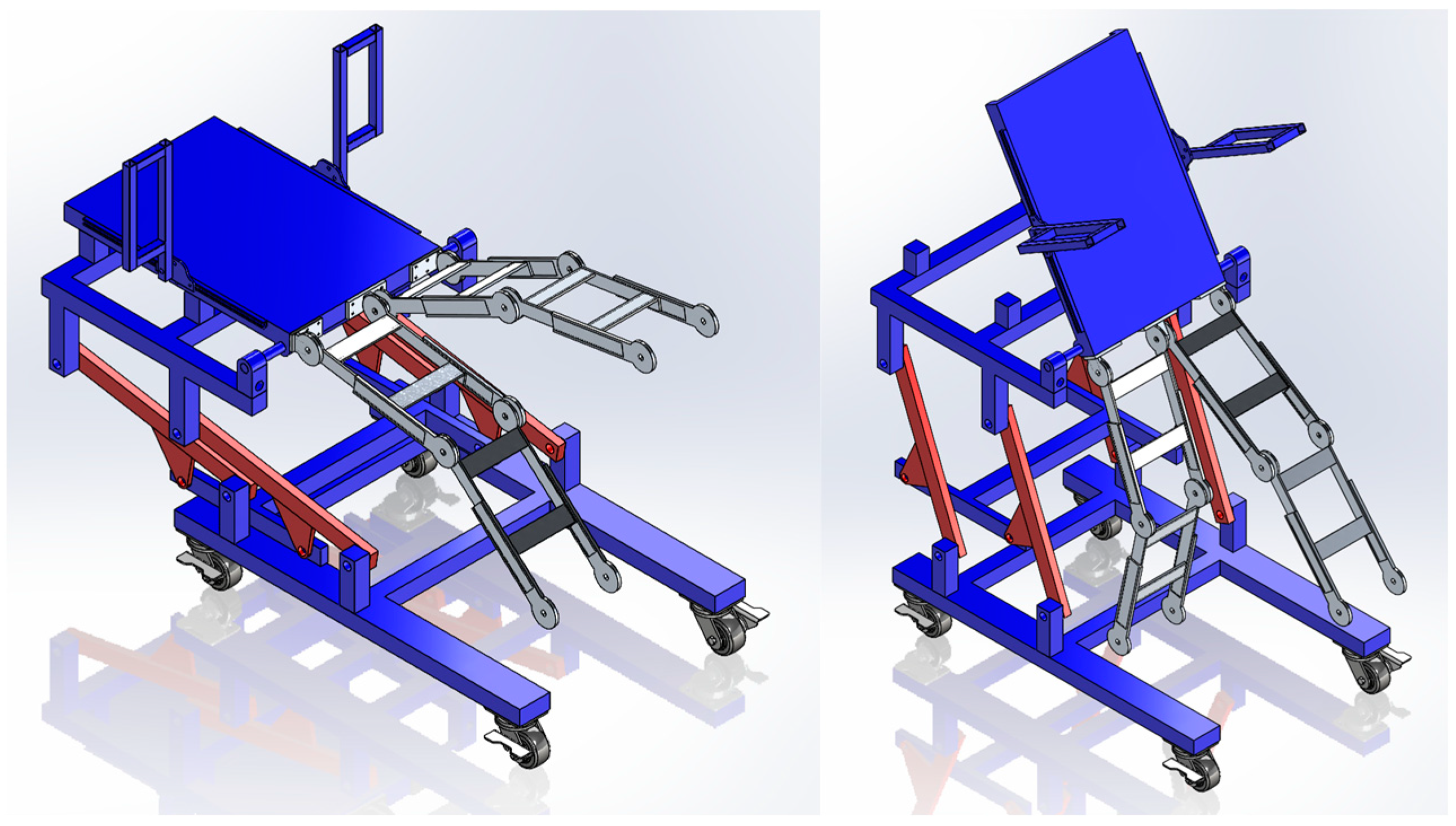
3.2.1. Concept 1: Rotation with a Gearbox (Rotational Lift)
This design incorporates a rotational lift table, powered by four motors, to elevate the patient and enable the placement of the RWTD underneath, as shown in
Figure 4. The tilting functionality is achieved through a gearbox motor, which effectively reduces the torque exerted on the motor during the tilting process of the table and patient.
3.2.2. Concept 2: Scissor Lift with a Linear Actuator (Scissor Lift)
This design incorporates a two-part mechanism lift, as shown in
Figure 5. The initial mechanism utilizes a piston-driven scissor lift to raise the patient, allowing for proper positioning of the RWTD in an upright vertical orientation. To achieve the desired tilt, ranging from 0 to 90 degrees, a combination of a linear actuator and a pivot arm is employed.
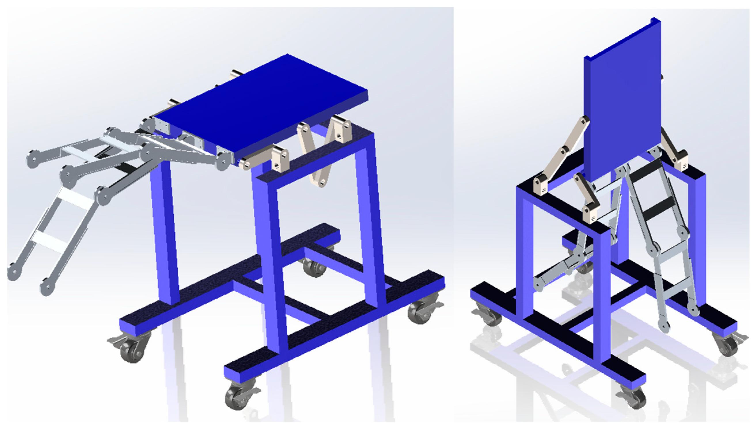
3.2.3. Concept 3: Four-Bar Linkage with Double Pivot (Double Pivot Lift)
This design features a double pivot mechanism with a single central pivot point, as shown in
Figure 6. As the back pivot arm rotates counterclockwise, the front pivot arm rotates clockwise, resulting in a motion that elevates the back of the table while simultaneously pulling the front towards the rear, repositioning the patient to a 90-degree angle.
3.3. Structural Analysis Using FEA
To accurately assess the merits of the three conceptual design configurations, a structural analysis was performed for each design using ANSYS Workbench 2023 R2, a renowned finite element analysis software. In the pursuit of simulating a human patient, each model featured a central point mass weighing 136 kg (equivalent to 300 lbs), precisely characterized by the moment of inertia data provided by NASA [
25].
Moreover, to emulate real-world conditions, an additional point load was introduced specifically for the robotic walking training device which was connected to the base of the backboard. All three devices were anchored with their wheels securely fixed to the ground, and a gravitational load was applied to replicate authentic forces acting upon the system.
Furthermore, in consideration of the mechanical components, fixed joints were strategically incorporated where motors would be situated, and revolute joints were thoughtfully positioned to simulate pin connections. To ensure the reliability of the analysis, a mesh convergence study was meticulously conducted for each configuration, employing the convergence tool to scrutinize the von Mises stresses.
Table 3 provides the outcomes of the FEA conducted for each design configuration. Specifically, it records the maximum deflection and maximum stress values at various angles of tilt. The safety factor was subsequently determined, employing the yield stress characteristic of 316 steel, the material employed for all design variants.
In the analysis results, Concept 1 exhibited the highest stress levels when the patient was positioned in the supine (horizontal) orientation, yielding a safety factor of 3.69. Concept 2 similarly registered the greatest stress levels when the patient was in the supine position, but with a notably higher safety factor of 6.58. Concept 3, on the other hand, manifested its highest stress levels when the patient was in the upright (vertical) position, accompanied by a safety factor of 5.99. Most common lift devices are designed with a safety factor of 3 or more, making all the designs acceptable in terms of safety factors.
3.4. SolidWork Motion Analysis
3.4.1. Center of Gravity (CoG) Analysis
To assess the stability of each design and thereby ensure the safety of both the patient and the operators working in the vicinity of the device, a comprehensive center of gravity (CoG) analysis was undertaken. This analysis involved the utilization of SolidWorks’ mass features, both with and without a patient situated on the device to calculate the ideal location for a centralized distribution center in the RWTD.
The primary aim of this analysis was to determine the susceptibility of each device to tipping, which was achieved through the application of fundamental principles of statics. By assessing the position of the center of gravity, this study offers valuable insights into the overall stability of each design under various conditions, facilitating informed decisions to enhance safety and operational efficacy.
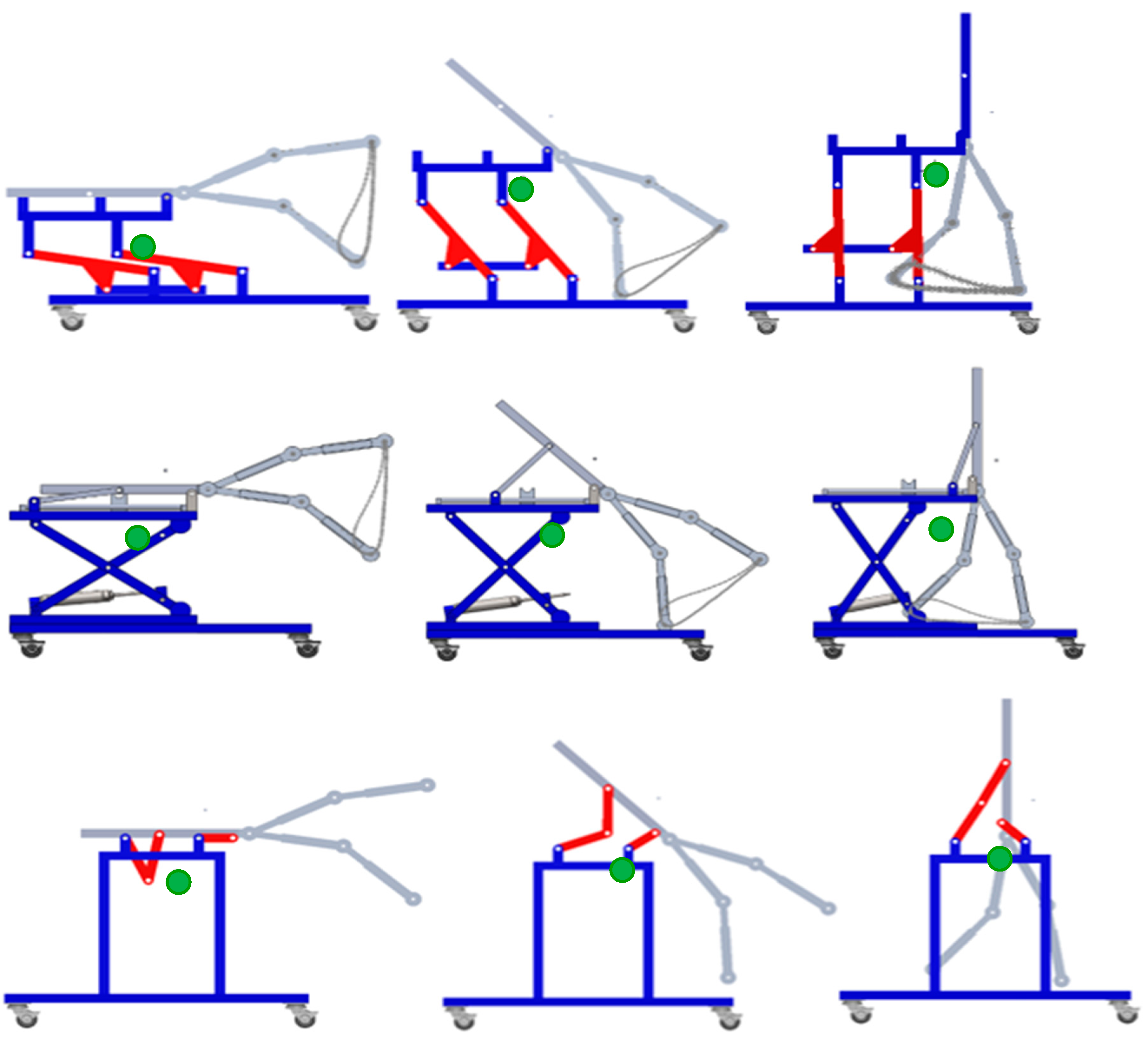
Figure 7 shows the movement of the CoG for each design. The images show each device in the 0, 45, and 90 positions. In general, the CoG moves forward and rises as the patient is relocated from the supine position to the upright standing position.
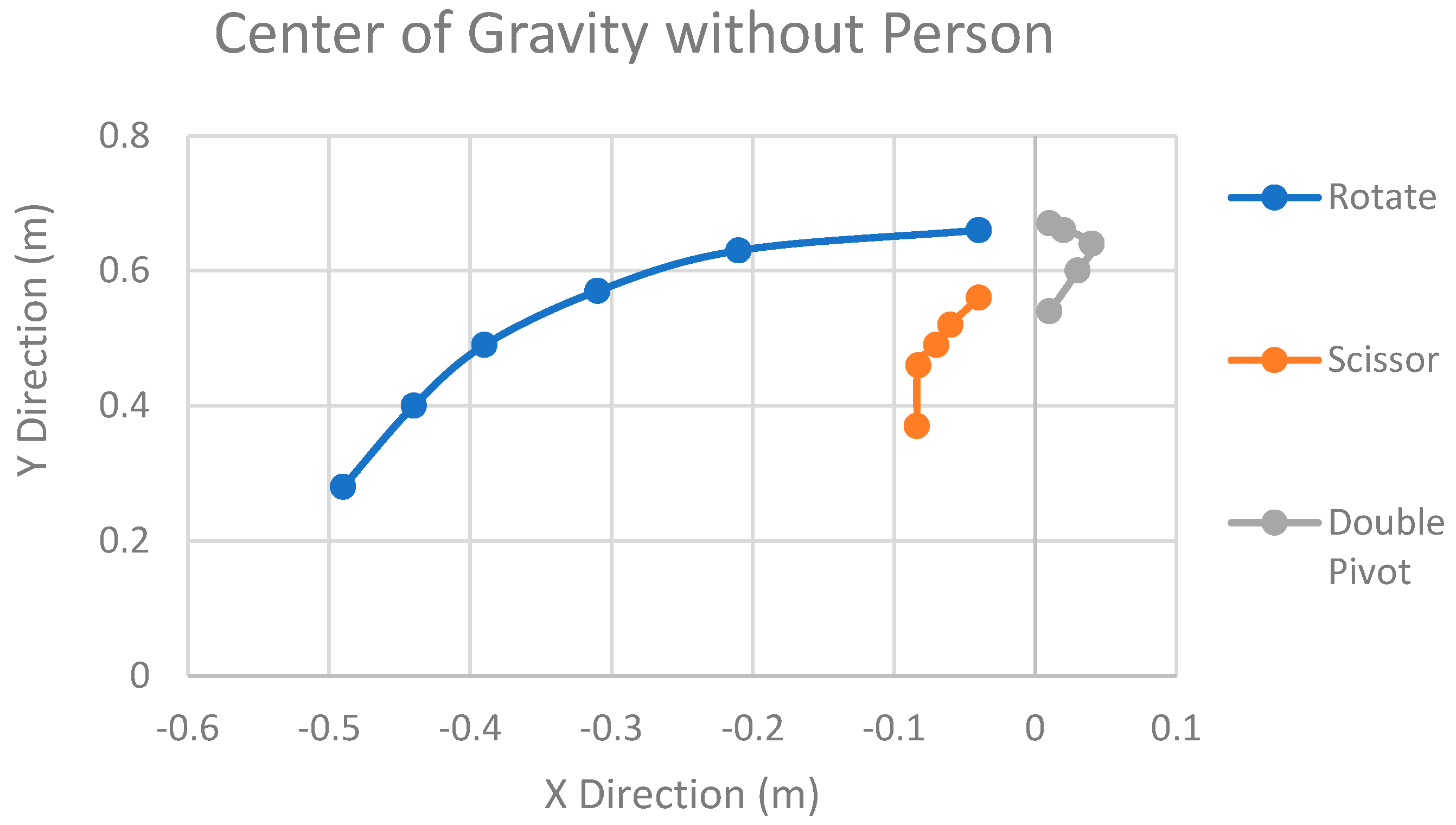
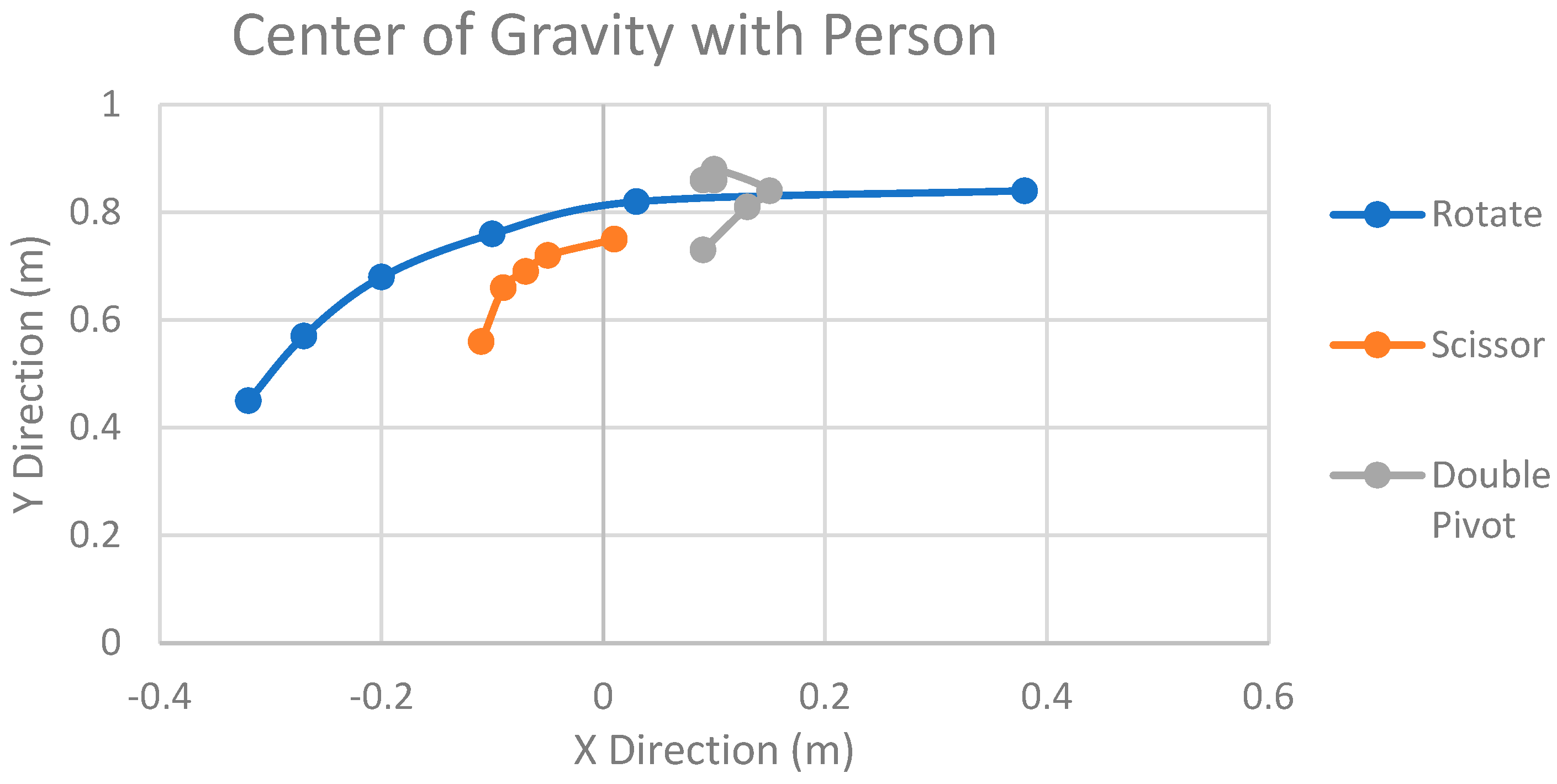
Figure 8 below presents the outcomes of the analysis for each of the designs, with each axis representing the respective position of the center of mass. This analysis encompassed the calculation of the CoG at various angles throughout the motion of each design.
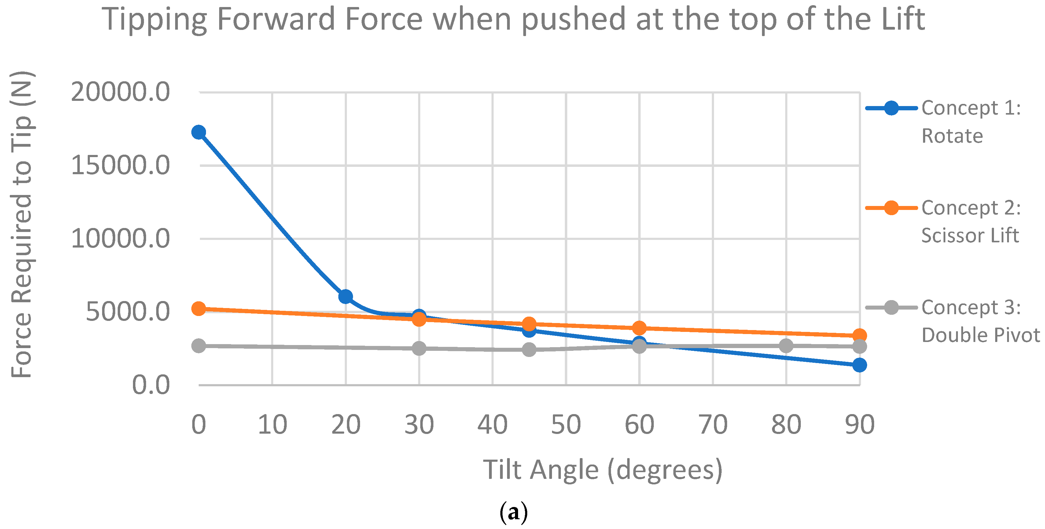
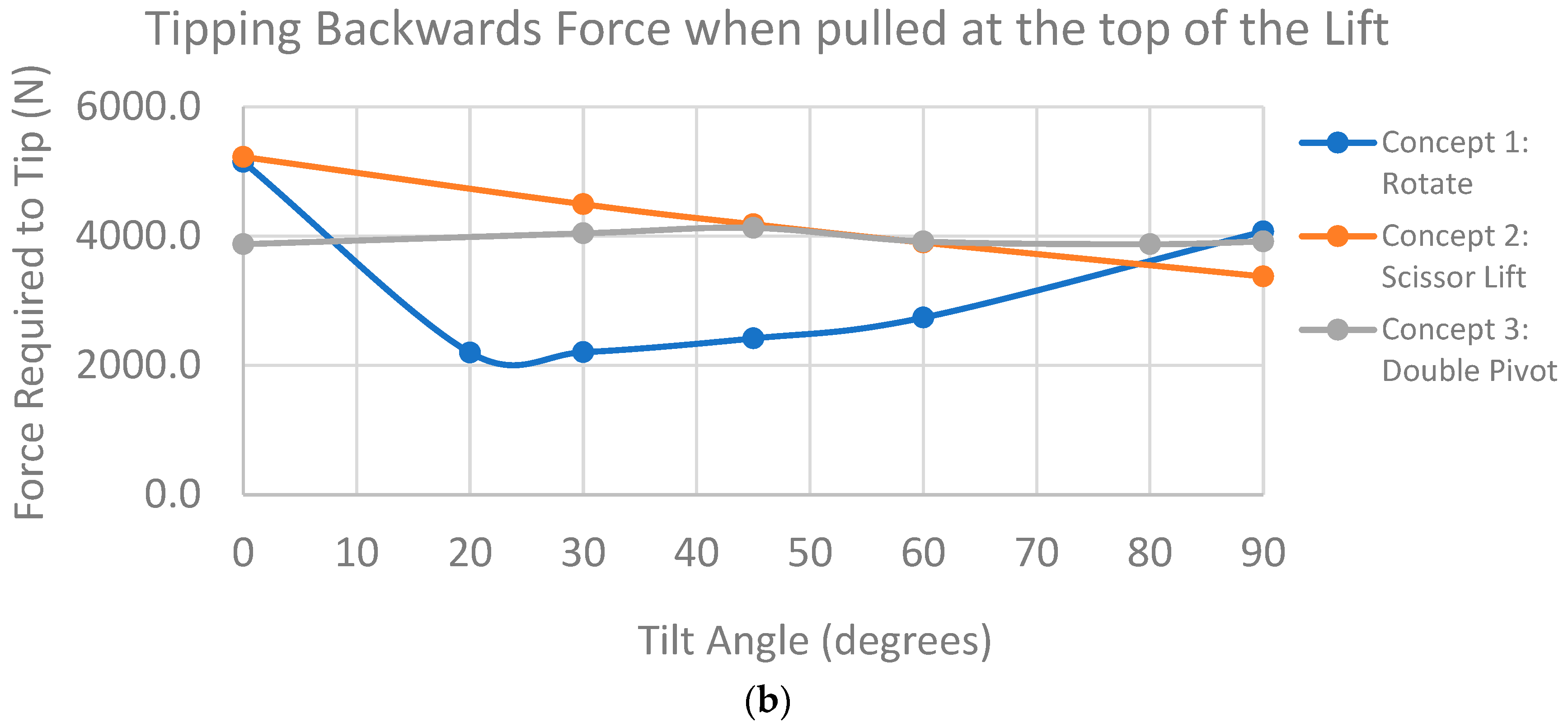
These centers of gravity calculations subsequently served as a pivotal component in determining the propensity for each design to tip over. The ease of tipping, a crucial factor in ensuring the safety of the device, was derived from these results. Large movements in the CoG could interfere with patient safety and comfort during the transition. To improve this issue, balancing using a counterweight on the base of the RWTD will be considered in future work. This information is paramount for evaluating the stability and safety of the device under diverse conditions and motions. Tipping was defined as the force required to lift the rear/front wheel. Forward tipping refers to lifting of the rear wheel while backward tipping refers to lifting of the rear wheel when pushed horizontally from the top of the lift platform. The results can be seen below in
Figure 9.
3.4.2. Lift Forces
Using SolidWorks motion analysis, lift forces and torques were recorded for each design under gravitational loading with simulated motors. Linear and rotation motors were used to simulate the real-world motion of each device.
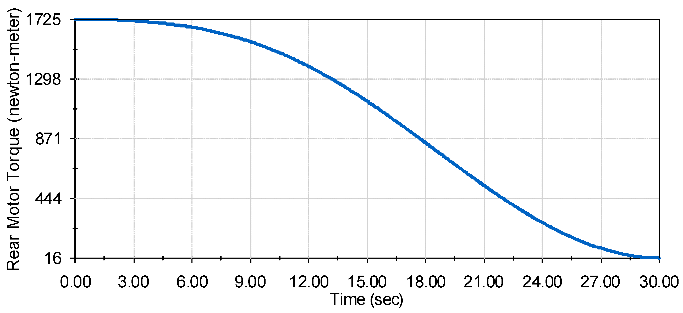
Design 1: Rotational Lift
Design 1 (rotational lift shown in
Figure 4) employs five rotational motors for its lift mechanism, with four situated at the base facilitating upward rotation and another at the top controlling patient tilt. The motion analysis for the lift mechanism from 0 to 90 degrees over 30 s yielded force results as depicted in
Figure 10.
Notably, all motor torque charts exhibit smooth motion without spikes, validating a seamless experience for the patient. The rear rotational motors at the base experience the highest torque at 859 Newton meters each, while the front rotational motors encounter the least torque at 32 N-m each. The unique V pattern observed in the tilt control motor’s torque (maxing at 420 N-m) aligns with the device countering gravity during the initial 45 degrees and then working against gravity to position the patient upright.
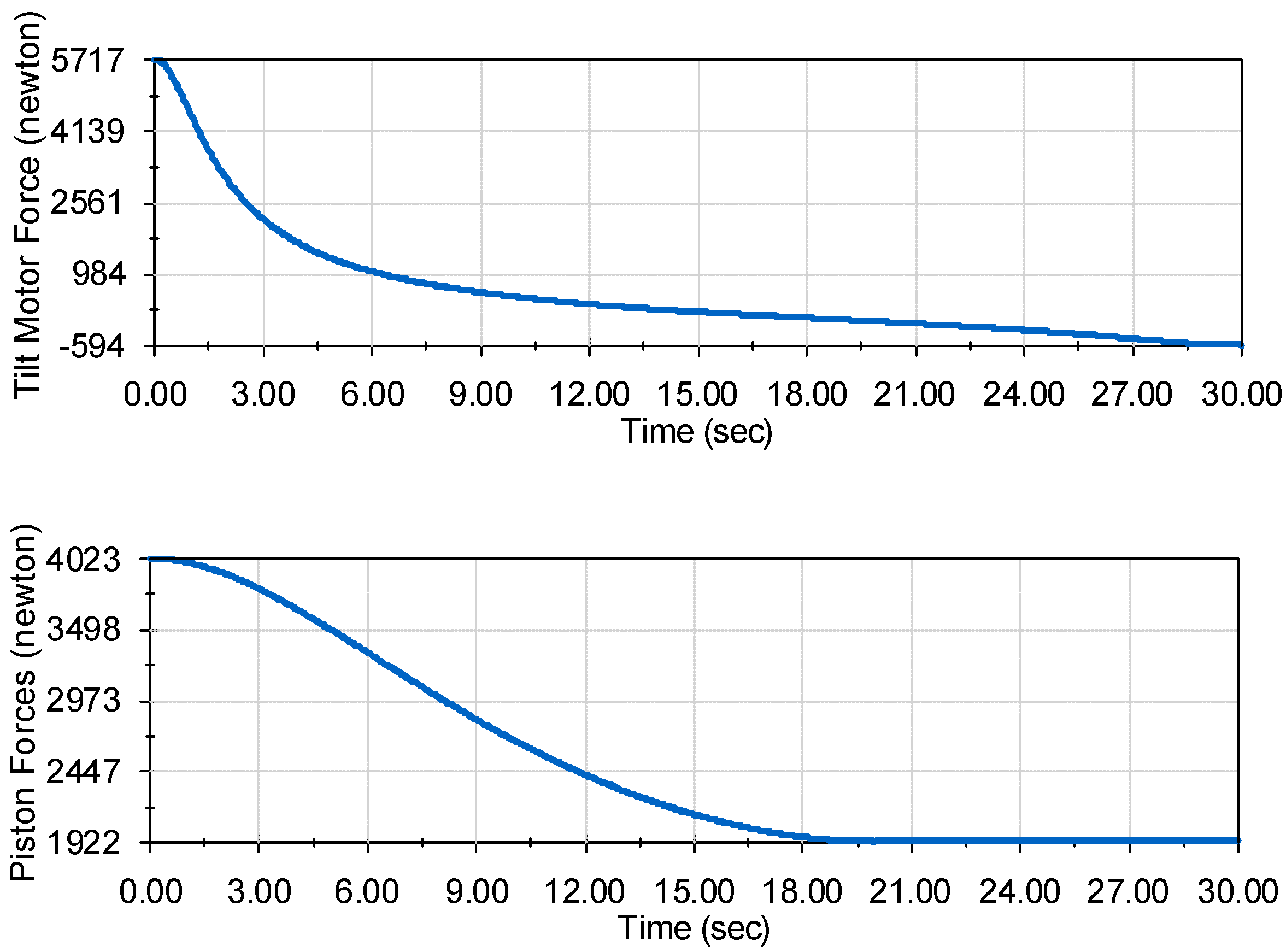
Design 2: Scissor Lift
Design 2 (scissor lift shown in
Figure 5) introduces a sophisticated mechanism involving two distinct motor techniques. The lower portion of the lift relies on a piston system, where extension lowers the lift, and retraction raises it. Simultaneously, the upper portion responsible for controlling the patient’s tilt integrates two linear actuators on each side.
The forces required for these linear actuators are depicted in
Figure 11, revealing an equitable distribution of forces resulting in a maximum force of 3000 N at the initial movement phase. Notably, the motor force undergoes a shift of around 18 s, becoming negative as the motor restricts the force of gravity rather than actively pushing against it. In contrast, the piston system exerts a maximum force of 4000 N, showcasing its robust lifting capacity.
Design 3: Double Pivot Lift
Design 3 (double pivot lift shown in
Figure 6), a complex configuration involving four motors, presents a nuanced approach to the RWTD lift mechanism. Two motors are strategically positioned at the back, while the other two are situated on the front pivots. The motion is orchestrated in a counterclockwise direction towards the rear of the device, primarily focused on raising the RWTD. An integral aspect of this design is its concerted effort to maintain the center of gravity of the device in a consistent position throughout the lifting process. This attention to the center of gravity dynamics is pivotal for ensuring the stability and controlled motion of the device during elevation.
As depicted in
Figure 12, the left graph illustrates the lift torques experienced by the rear motors during the lifting operation. The maximum lift torque for each rear motor peaks at 174.4 Newton meters, a critical moment occurring around the 12-s mark when the tilt angle is near 45 degrees. This specific torque application is strategically timed to manage the transition phase of the device’s tilt. Meanwhile, the right graph in
Figure 11 details the lift torque on the front motors throughout the lift process. At the 90-degree tilt position, the front motors experience their maximum lift torque of 300.5 Newton meters. Post the 60-degree tilt position, the tilt angle becomes exclusively controlled by the front motors, effectively guiding the device to the precise upright position. This detailed torque distribution across the rear and front motors highlights the intricate interplay between various components in the double pivot design, underscoring its commitment to maintaining stability, precise motion control, and optimum lifting performance.
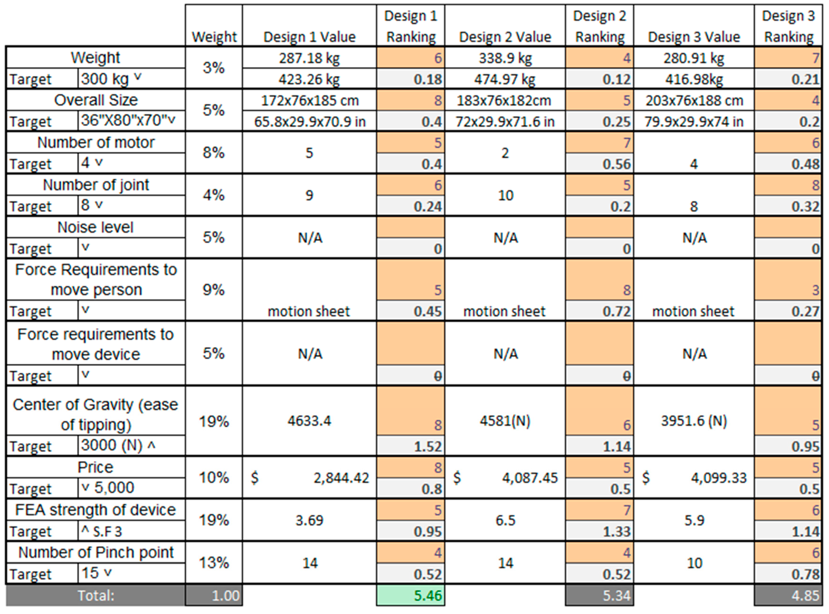
3.5. Decision Matrix
To impartially assess each design, a comprehensive decision matrix was formulated, encompassing 11 distinct weighted criteria, each of which pertains to the RWTD lift mechanism as shown in
Figure 13. These criteria serve as diverse requirements essential for evaluating the performance and functionality of the RWTD. The 11 criteria are as follows:
Weight
Size
Number of Motors
Number of Joints
Noise Level
Force Required to Lift Patient
Force Required to Move the Device
Center of Gravity (Tipping)
Price
FEA Structural Strength
Number of Pinch Points
Each of these criteria addresses a pivotal aspect of RWTD’s operation. For instance, criteria such as weight, size, and force required to move are used to assess the device’s transportability. Others, such as the number of pinch points, center of gravity, and noise level, focus on evaluating the device’s safety for both patients and therapists.
To establish the weighted values for these criteria, an algorithmic approach was adopted. This approach derives the weights based on correlations between customer requirements and functional specifications. The highest level of importance was assigned to the center of gravity, as it plays a substantial role in the device’s safety, functionality, and structural design. Conversely, the overall weight of the device received a lower importance rating since, given that the device is primarily motor-driven, it remains a significant consideration but is comparatively less critical than the other criteria.
Among the three design variants, “Rotational Lift,” representing Design 1, emerged as the top performer in the decision matrix. It obtained the highest total score, with noteworthy results in several key areas, particularly excelling in center of gravity, price, and size.
In
Figure 13, the scoring system utilized a range from 1 to 9 to assess each criterion in relation to the target goal. A score of 9 signified an excellent achievement, while a score of 6 indicated performance above the average standard. Scores of 3 and 1 were assigned to criteria that were below average and poor, respectively.
In the decision matrix, two criteria, noise and force required to move, were not assessed due to specific constraints and conditions.
The noise criterion was excluded from the evaluation because a noise analysis could not be conducted using a CAD (computer-aided design) model. Accurately assessing the noise level of the device necessitates a physical mechanism to generate the noise, which is typically achieved through experimental testing. Nonetheless, it is important to acknowledge that noise remains a critical aspect of the design, and it must adhere to OSHA (Occupational Safety and Health Administration) requirements, ensuring that it does not necessitate noise protective gear and complies with safety regulations.
The force required to move criterion was omitted from this analysis because all the designs featured the same wheel and base configurations. Consequently, the force required to push or move the device was considered directly proportional to the weight of the device. In such a scenario, this criterion became redundant for distinguishing between the design variants since it did not provide meaningful differentiation.
These exclusions were made based on the specific limitations and uniformities within the designs, but it is essential to recognize their significance in the broader context of the device’s functionality and safety. The robust performance of Design 1, particularly in terms of center of gravity, price, and size, underscores its strong suitability and competence with respect to these vital aspects of the RWTD design.
4. Discussion
The comprehensive evaluation of the three RWTD design configurations has yielded significant insights into their performance and functionality, offering valuable implications for medical equipment design and safety. Design 1, named “Rotate,” emerged as the superior choice, excelling in criteria such as center of gravity, price, and size. This aligns with established research emphasizing the pivotal role of these factors in ensuring patient safety and affordability in medical equipment design.
Despite the robust findings, it is crucial to acknowledge the study’s limitations. The exclusion of noise analysis due to the constraints of CAD models underscores the necessity for future research to address this aspect, given the potential impact of excessive noise on both patients and healthcare professionals. Similarly, the exclusion of the force required to move criterion underscores the significance of standardization in design elements, emphasizing the need for optimization to enhance maneuverability and minimize physical effort. Additionally, decision matrices can pose challenges in ranking values. Incorporating customer feedback and patient perception in future studies could enhance the ranking algorithm with reduced subjectivity. For example, patient perception of the kinematics could be an interesting scientific contribution to these devices.
The implications of these findings extend to patient care and medical equipment safety. The emphasis on criteria such as center of gravity and structural strength aligns with the overarching goal of minimizing tipping risks and ensuring the safety of patients and healthcare providers. Considerations like the number of pinch points underscore the importance of prioritizing patient comfort and safety in equipment design.
Future research directions are identified in optimizing the device’s motion range from 0 to 90 degrees tilt for enhanced patient comfort. Additionally, exploring advanced technologies such as automation and smart sensors can further elevate the RWTD’s functionality, making it more accessible and safer for both patients and healthcare providers. Prioritizing criteria such as center of gravity, structural strength, and pinch points remains paramount for patient safety, harmonizing with the device’s smooth tilt range. The evaluation of patients’ experiences will be crucial in optimizing both comfort and safety aspects.
In conclusion, the focus of future research should be on refining the RWTD design by enhancing tilt motion capabilities, integrating emerging technologies, and addressing design limitations. The ultimate objective is to create a device that optimizes patient care, streamlines clinical processes and prioritizes comfort, safety, and usability for both patients and healthcare professionals.
5. Conclusions
In summary, the design selection process adheres to the engineering design methodology, commencing with the description of a well-defined problem, assimilating background information, generating multiple potential solutions, and culminating in the meticulous analysis and selection of the most optimal solution. Three distinct CAD models were systematically created and subjected to comprehensive evaluations, employing finite element analysis and motion analysis techniques to assess the center of gravity, lift forces, and torques during operational scenarios.
The evaluation process involved the utilization of a design decision matrix featuring 11 distinct criteria, aimed at identifying the design that optimally balances safety and functionality for both the patient and collaborative lower exoskeleton. Notably, the exclusion of noise level and force required to move from the design criteria was deliberate, considering the infeasibility of determining noise levels through a CAD model and the uniformity in the base and wheel setup across all designs, fostering consistency in the focus area of lift and tilt mechanisms.
The results were consistent with expectations, as Design 1 showcased superior performance in terms of price, stability, and strength. Design 2 excelled in the force required to move the patient and demonstrated strength, albeit falling behind in price and stability. Design 3 displayed excellence in ease of motion and safety but exhibited shortcomings in strength and cost. Overall, Design 1 received the highest score in the matrix evaluation, establishing it as the top-performing design.
This research holds substantial significance for advancing the robotic walking training device by eliminating the current harnessed system prevalent in contemporary gait rehabilitation with exoskeleton robotic devices. Placing the patient in a supine starting position enhances the ease of use for both patients and healthcare professionals, opening avenues for individuals who are unable to walk. The device, when employed in the supine position, facilitates patient exercise, promoting increased blood flow to the lower extremities and addressing a critical aspect of rehabilitation.
Author Contributions
Conceptualization, A.B., C.-H.G. and B.R.; methodology, A.B., C.-H.G. and B.R.; software, A.B.; validation, C.-H.G. and B.R.; formal analysis, A.B.; investigation, A.B. and C.-H.G.; investigation, C.-H.G. and B.R.; resources, C.-H.G. and B.R.; data curation, A.B.; project administration, C.-H.G. and B.R.; writing—original draft preparation, A.B.; writing—review and editing, C.-H.G. and B.R.; visualization, A.B. and C.-H.G.; supervision, C.-H.G. and B.R.; project administration, C.-H.G. and B.R. All authors have read and agreed to the published version of the manuscript.
Funding
This research received no external funding.
Informed Consent Statement
Not applicable.
Data Availability Statement
The data presented in this study are available on request from the corresponding author. The data are not publicly available due to privacy.
Acknowledgments
This project has been partially supported by Y.T. Wang at the University of Texas at Tyler (currently at Rochester Institute of Technology) since 2019. Goh is grateful for his support in building a prototype of the robotic walking training device (RWTD).
Conflicts of Interest
The authors declare no conflicts of interest.
References
- Eng, J.J.; Tang, P.-F. Gait training strategies to optimize walking ability in people with stroke: A synthesis of the evidence. Expert Rev. Neurother. 2007, 7, 1417–1436. [Google Scholar] [CrossRef] [PubMed]
- States, R.; Pappas, E.; Salem, Y. Overground physical therapy gait training for chronic stroke patients with mobility deficits. Cochrane Database Syst. Rev. 2009, 2009, CD006075. [Google Scholar] [CrossRef] [PubMed]
- Boden-Albala, B.; Litwak, E.; Elkind, M.; Rundek, T.; Sacco, R.L. Social isolation and outcomes post stroke. Neurology 2005, 64, 1888–1892. [Google Scholar] [CrossRef] [PubMed]
- Guzik, A.; Drużbicki, M.; Wolan-Nieroda, A. Assessment of two gait training models: Conventional physical therapy and treadmill exercise, in terms of their effectiveness after stroke. Hippokratia 2018, 22, 51–59. [Google Scholar] [PubMed]
- States, R.A.; Salem, Y.; Pappas, E. Overground Gait Training for Individuals with Chronic Stroke: A Cochrane Systematic Review. J. Neurol. Phys. Ther. 2009, 33, 179–186. [Google Scholar] [CrossRef]
- Hesse, S.; Werner, C.; Bardeleben, A.; Barbeau, H. Body weight-supported treadmill training after stroke. Curr. Atheroscler. Rep. 2001, 3, 287–294. [Google Scholar] [CrossRef]
- Mao, Y.-R.; Lo, W.L.; Lin, Q.; Li, L.; Xiao, X.; Raghavan, P.; Huang, D.-F. The effect of body weight support treadmill training on gait recovery, proximal lower limb motor pattern, and balance in patients with subacute stroke. BioMed Res. Int. 2015, 16, 175719. [Google Scholar] [CrossRef]
- Wright, A.; Stone, K.; Martinelli, L.; Fryer, S.; Smith, G.; Lambrick, D.; Stoner, L.; Jobson, S.; Faulkner, J. Effect of combined home-based, overground robotic-assisted gait training and usual physiotherapy on clinical functional outcomes in people with chronic stroke: A randomized controlled trial. Clin. Rehabil. 2021, 35, 882–893. [Google Scholar] [CrossRef] [PubMed]
- Alashram, A.R.; Annino, G.; Padua, E. Robot-assisted gait training in individuals with spinal cord injury: A systematic review for the clinical effectiveness of Lokomat. J. Clin. Neurosci. 2021, 91, 260–269. [Google Scholar] [CrossRef] [PubMed]
- Itoh, N.; Imoto, D.; Kubo, S.; Takahashi, K.; Hishikawa, N.; Mikami, Y.; Kubo, T. Gait training using a stationary, one-leg gait exercise assist robot for chronic stroke hemiplegia: A case report. J. Phys. Ther. Sci. 2018, 30, 1046–1051. [Google Scholar] [CrossRef] [PubMed]
- Li, Y.; Fan, T.; Qi, Q.; Wang, J.; Qiu, H.; Zhang, L.; Wu, X.; Ye, J.; Chen, G.; Long, J.; et al. Efficacy of a Novel Exoskeletal Robot for Locomotor Rehabilitation in Stroke Patients: A Multi-center, Non-inferiority, Randomized Controlled Trial. Front. Aging Neurosci. 2021, 13, 706569. [Google Scholar] [CrossRef]
- Thakur, K.; Banwait, S.S.; Bedi, R. Finite element analysis of U-frame of robotic gait trainer for rehabilitation. IOP Conf. Series: Mater. Sci. Eng. 2022, 1248, 012068. [Google Scholar] [CrossRef]
- Gad, P.; Gerasimenko, Y.; Zdunowski, S.; Turner, A.; Sayenko, D.; Lu, D.C.; Edgerton, V.R. Weight bearing over-ground stepping in an exoskeleton with non-invasive spinal cord neuromodulation after motor complete paraplegia. Front. Neurosci. 2017, 11, 333. [Google Scholar] [CrossRef]
- Gil-Agudo, Á.; Megía-García, Á.; Pons, J.L.; Sinovas-Alonso, I.; Comino-Suárez, N.; Lozano-Berrio, V.; Del-Ama, A.J. Exoskeleton-based training improves walking independence in incomplete spinal cord injury patients: Results from a randomized controlled trial. J. Neuroeng. Rehabil. 2023, 20, 36. [Google Scholar] [CrossRef] [PubMed]
- Unluhisarcikli, O.; Mavroidis, C.; Bonato, P.; Pietrusisnki, M.; Weinberg, B. Lower Extremity Exoskeleton for Gait Retraining. U.S. Patent 2013/0226048 A1, 29 August 2013. [Google Scholar]
- Lee, C.-S.; Li, I.-H.; Chiang, H.-H.; Lee, L.-W.; Hong, F.-C.; Chen, R.-P.; Chen, W.-G. Pneumatic Lower Extremity Gait Rehabilitation Training System. U.S. Patent 10,292,892 B2, 21 May 2019. Available online: https://patents.google.com/patent/US10292892B2/en (accessed on 17 November 2023).
- Xu, R. A Novel Design of the Lower Limb Rehabilitation Robot. In Proceedings of the 2020 6th International Conference on Mechanical Engineering and Automation Science (ICMEAS), Moscow, Russia, 29–31 October 2020. [Google Scholar]
- Kazerooni, H.; Steger, R.; Huang, L. Hybrid Control of the Berkeley Lower Extremity Exoskeleton (BLEEX). Int. J. Robot. Res. 2006, 25, 561–573. [Google Scholar] [CrossRef]
- Goh, C.-H. ERI: Virtual Reality-Based Robotic Walking Training Device Development for Gait Training in Rehabilitation for Individuals with Spinal Cord Injury. University of Texas at Tyler: Tyler, TX, USA, 2021; (Unpublished work). [Google Scholar]
- Anthony, J.; Goh, C.-H.; Wang, Y.T. Redesign of Leg Assembly and Implementation of Reinforcement Learning for Robotic Walking Training Device. In Proceedings of the KSME Annual Meeting 2022, Jeju, Korea, 9–12 November 2022. [Google Scholar]
- Khandani, S. Engineering Design Process, University of Guelph. 2005. Available online: https://www.uoguelph.ca/engineering/sites/uoguelph.ca.engineering/files/public/EngineeringProcess.pdf (accessed on 29 July 2023).
- EngMorph. Aspect Ratio Calculation for 2D Elements. 2023. Available online: https://www.engmorph.com/2d-element-aspect-ratio-calc (accessed on 22 December 2023).
- Dassault Systems. Mesh Quality Checks. 2021. Available online: https://help.solidworks.com/2021/english/SolidWorks/cworks/c_mesh_quality_checks.htm (accessed on 22 December 2023).
- FEA Tips. ANSYS Metrics Explained. 2023. Available online: https://featips.com/2022/11/21/ansys-mesh-metrics-explained/ (accessed on 22 December 2023).
- NASA Aeronautics and Space Administration. Anthropometry and Biomechanics. 2019; Volume 1. Available online: https://msis.jsc.nasa.gov/sections/section03.htm (accessed on 20 November 2023).
| Disclaimer/Publisher’s Note: The statements, opinions and data contained in all publications are solely those of the individual author(s) and contributor(s) and not of MDPI and/or the editor(s). MDPI and/or the editor(s) disclaim responsibility for any injury to people or property resulting from any ideas, methods, instructions or products referred to in the content. |
© 2023 by the authors. Licensee MDPI, Basel, Switzerland. This article is an open access article distributed under the terms and conditions of the Creative Commons Attribution (CC BY) license (https://creativecommons.org/licenses/by/4.0/).


