
Soil–Structure Interaction Analysis Using the Finite Element Method in Thin-Walled Steel Pipes Buried under Haul Roads


Abstract
:1. Introduction
- The pipe bedding effect constant , which depends on the pipe bedding angle α;
- The deflection factor for installation time ;
- The dead load , which is commonly estimated using the Marston’s equation or its derivatives;
- The live load , which can be estimated using the Boussinesq or Timoshenko equations or their derivatives;
- The cube of the mean radius of the pipe r.
- The product of the elasticity modulus, , and the inertia moment of the pipe, ;
- The lateral soil stiffness of the pipe, with value of , where the value 0.061 corresponds to the value of β for an angle of 50° (a typical value in this type of installations, but which may vary depending on the installation). is the modulus of soil reaction obtained from AWWA M11 standard tables [1], which has different recommended values and depends on soil properties, degree of compaction and depth [4].
- The backfill height over pipe H;
- The external diameter of the pipe ;
- The radius of contact , equivalent to the width of the tire;
- The equivalent contact area of the wheel track on the trench ;
- The impact factor which for the present study was considered to be 2.
- The pipe stiffness ;
- Its outside diameter ;
- Modulus of soil reaction ;
- Backfill height over pipe H;
- The water buoyancy factor , which is considered 1.0 for dry soils or those far from humid areas.
- It allows consideration of the nonlinearity and heterogeneity of the soil;
- It allows consideration of the interface between the pipe and the ground, that is, the slip or adhesion between both surfaces;
- It provides greater precision in the analysis of the vertical and horizontal displacements of the pipe;
- It uses mathematical models that allow the materials of the ground and the pipe to be characterized.
- Pipe outside diameter ;
- Pipe thickness , preselected according to hydraulic calculations;
- Pipe bedding angle , depending on the installation;
- Elasticity modulus of the pipe material, preselected according to the hydraulic calculations ;
- Elasticity modulus of the trench backfill, determined by a soil survey or recommended values (, , …, );
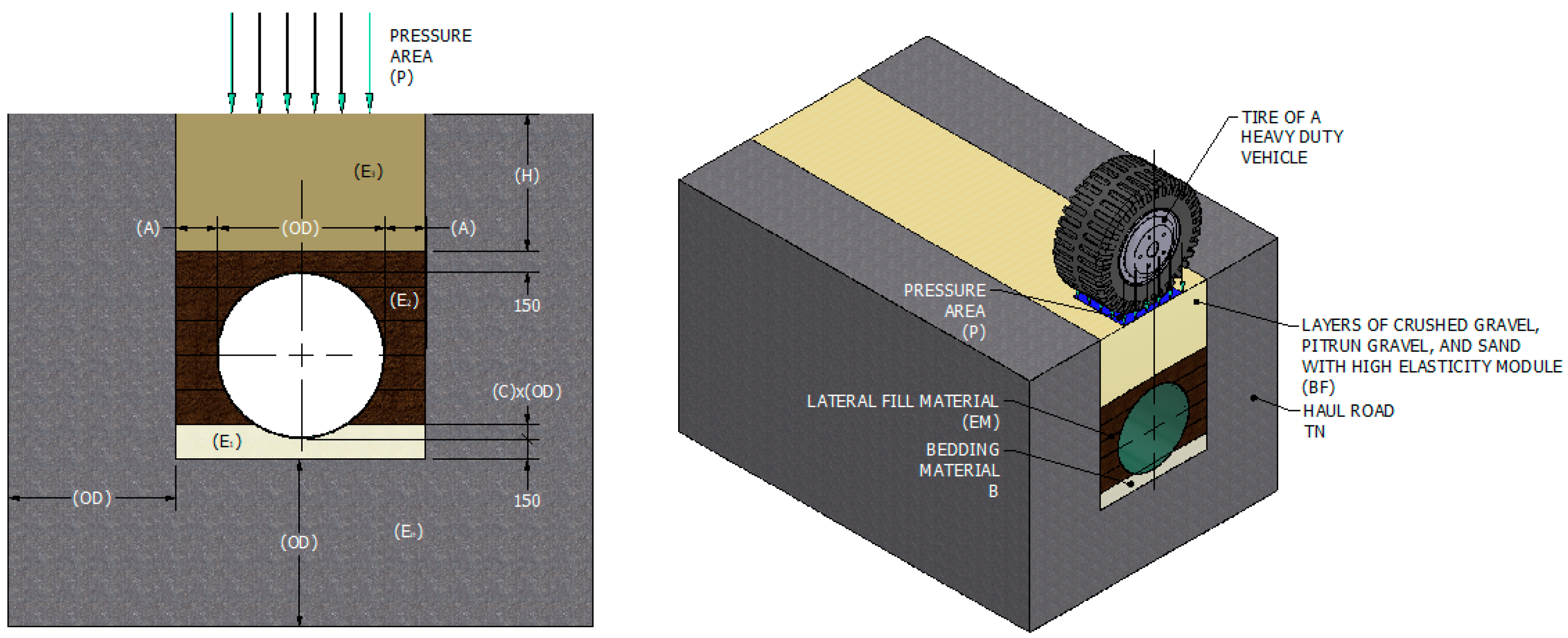
- The recommended geometric values in the typical trench section as width and height;
- The study was carried out using the mining vehicles shown in Table 1 as a reference.
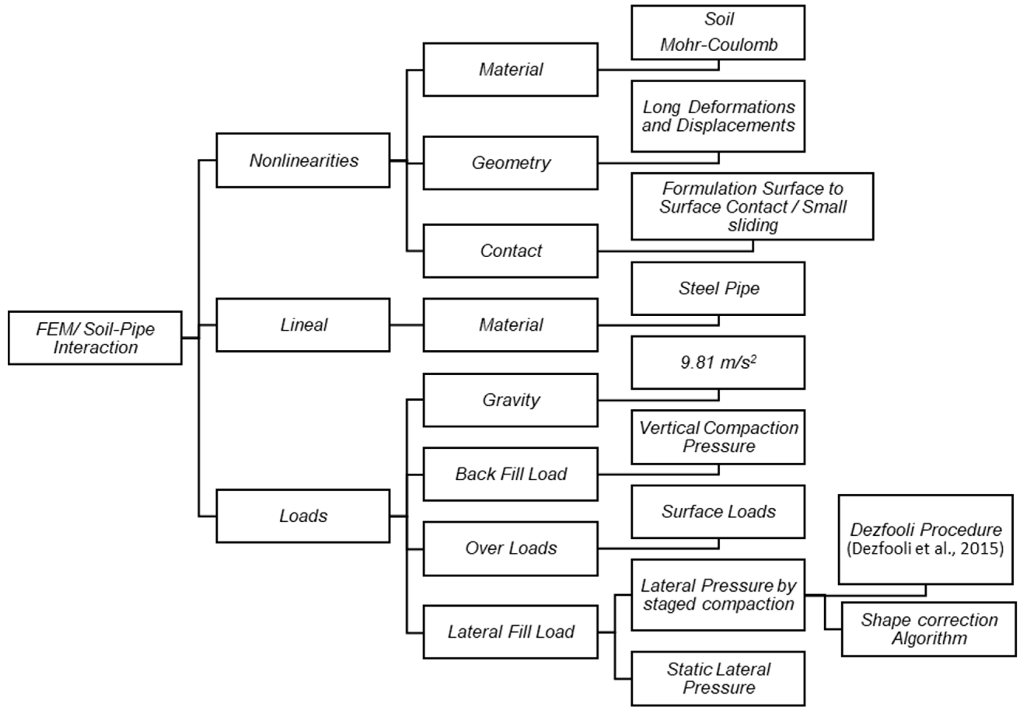
2. Proposed Finite Element Model
- The linearity range of the pipe;
- The applied loads, including soil and surface loads as well as lateral loads produced by the compaction process of the layers during installation.
2.1. Validation of Finite Element Model
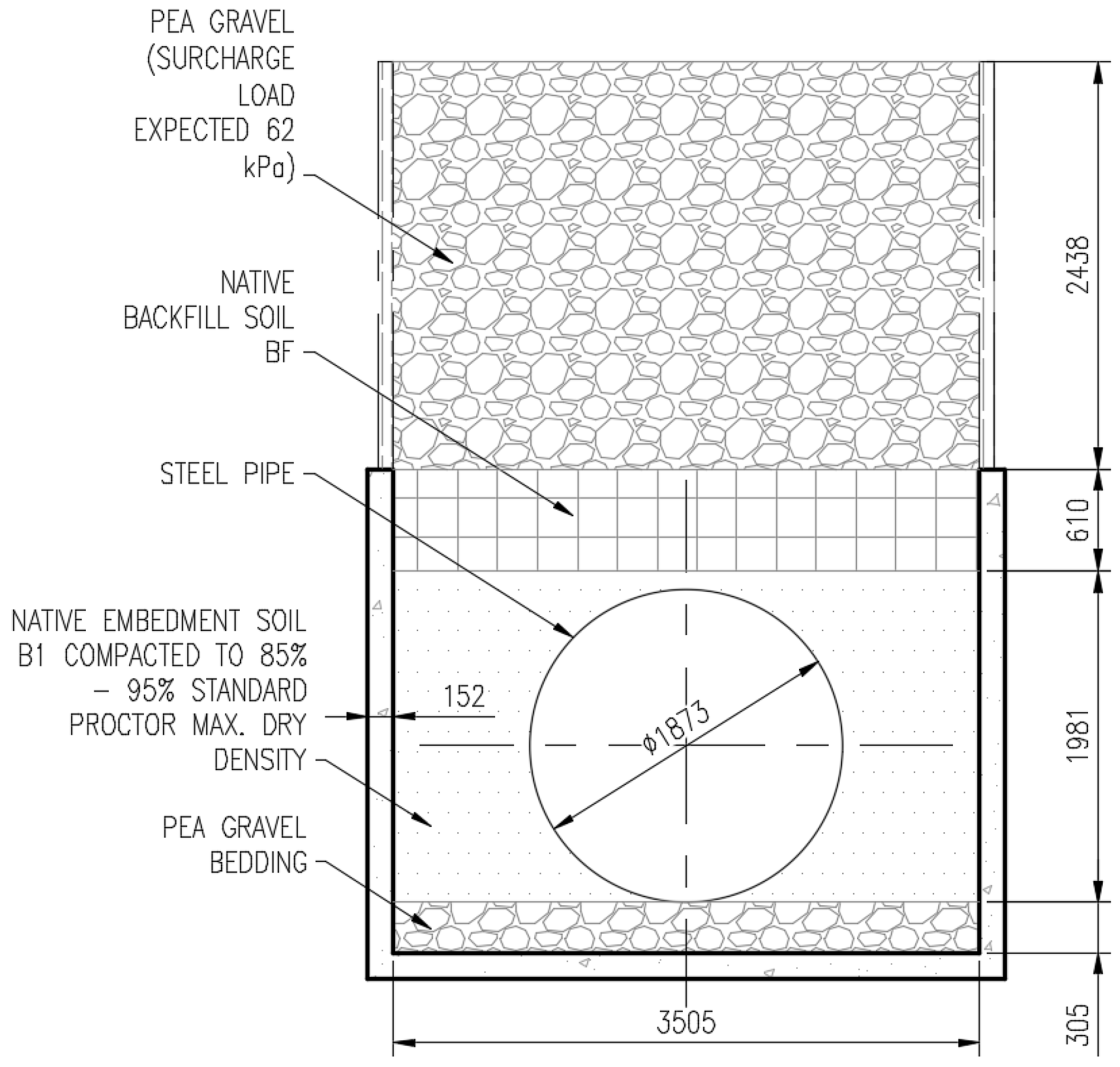
2.1.1. Model Geometry
2.1.2. Boundary and Contact Conditions
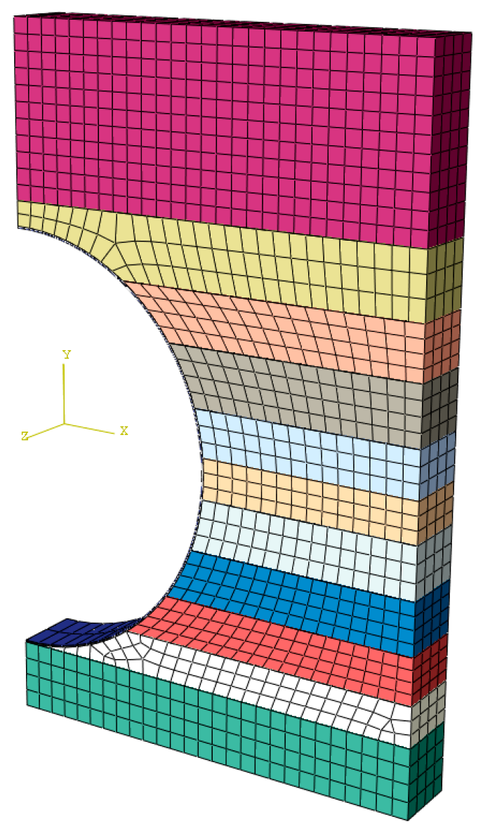
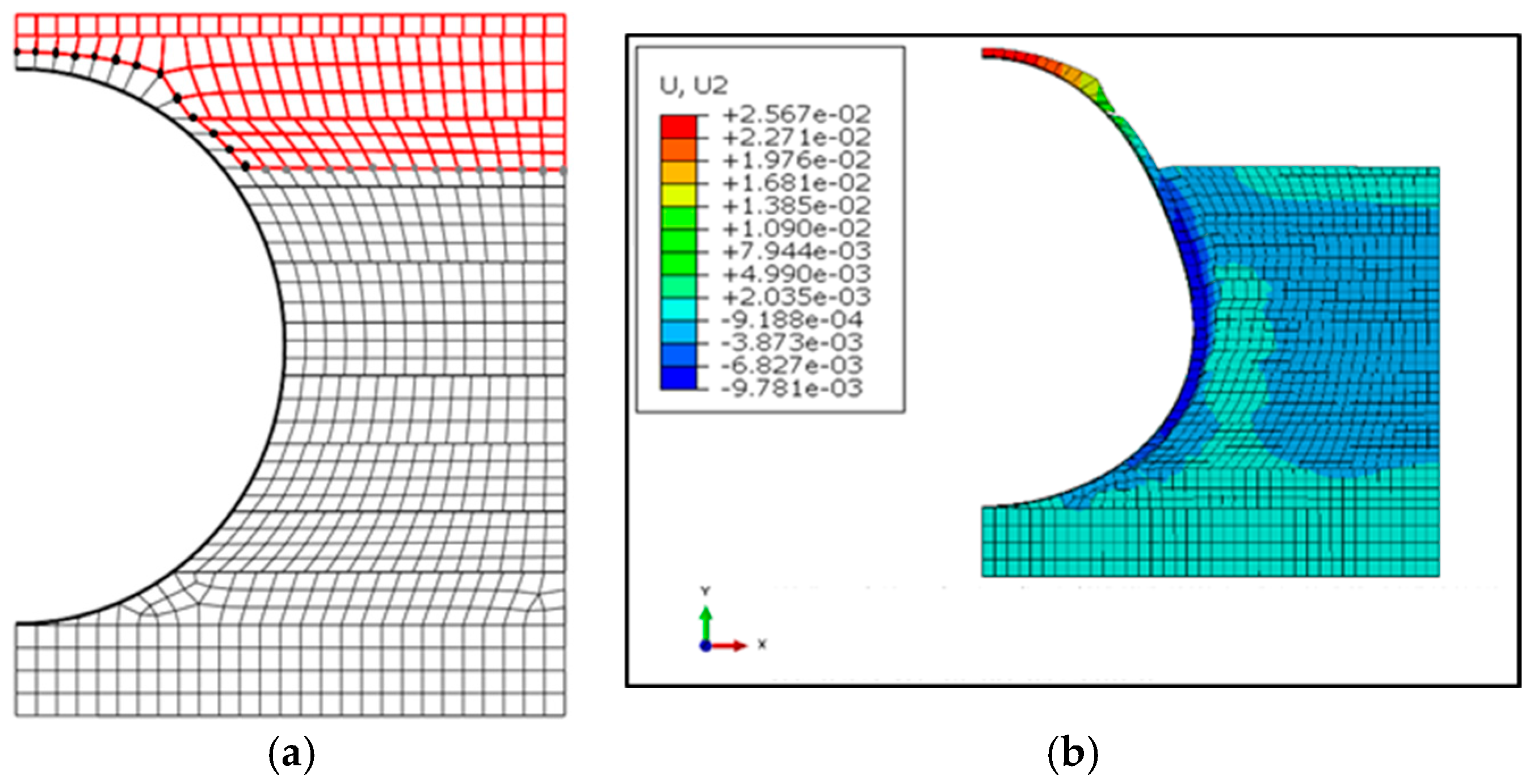
2.1.3. Meshing and Element Types
2.1.4. Lateral Loads and Numerical Simulation Procedure
- the cross-sectional area of the soil layer is ;
- the length of each layer is ;
- values are obtained as the product of the pipe thickness and its elasticity modulus;
- , is obtained multiplying the trench wall’s elasticity modulus by the trench wall’s length;
- is the elasticity modulus of the lateral fill;
- α is a virtual thermal coefficient;
- is the lateral soil stress. It is calculated from the value of the undrained cohesion Cu of the soil. Cu is measured in units of pressure. According to Clayton and Symons [30] the lateral soil pressure reaches up to 80% of Cu for soil plasticity indexes of 48%.
2.2. Sensitivity Analysis of the Finite Element Model
2.2.1. Compaction
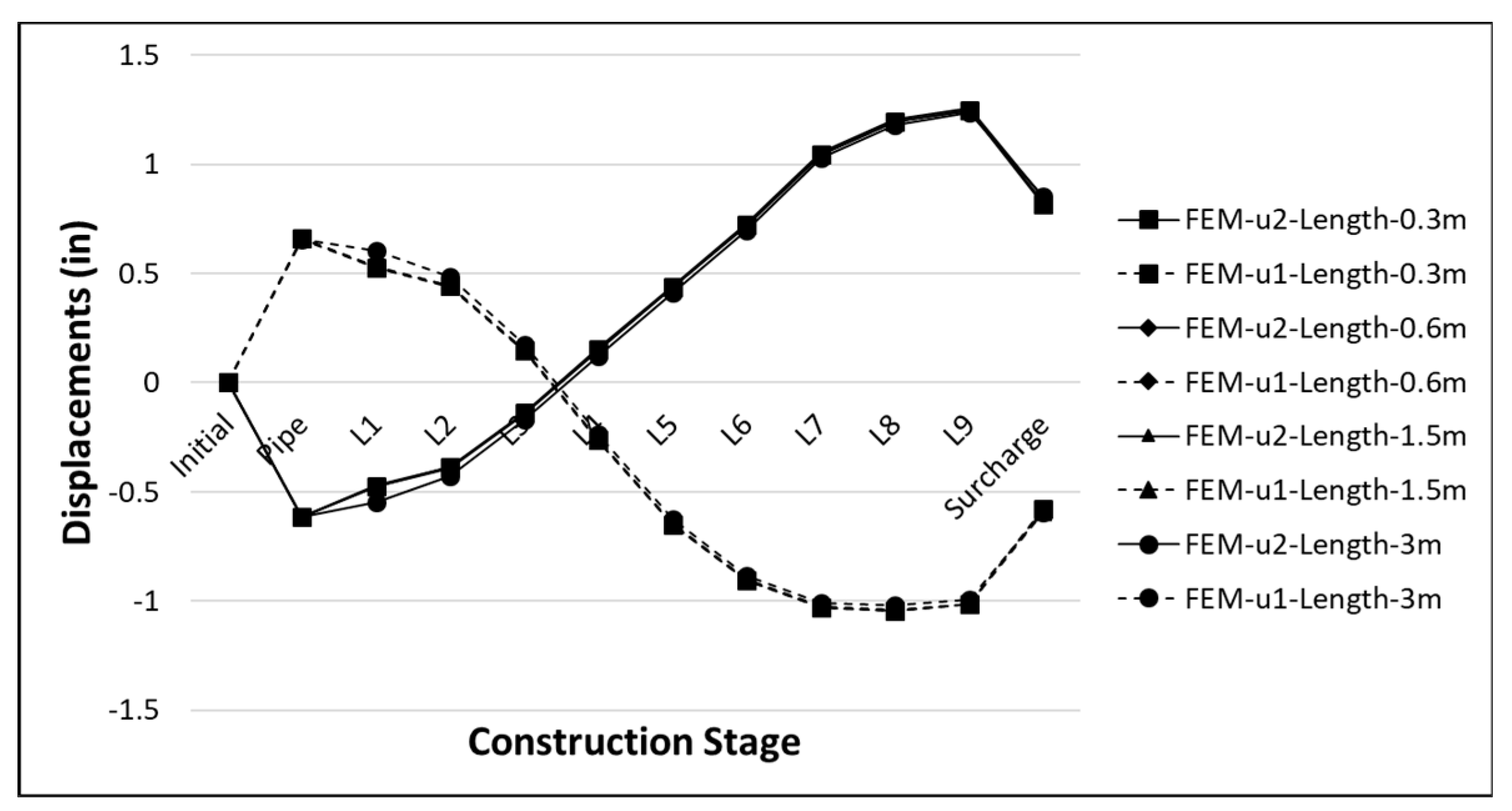
2.2.2. Model Length
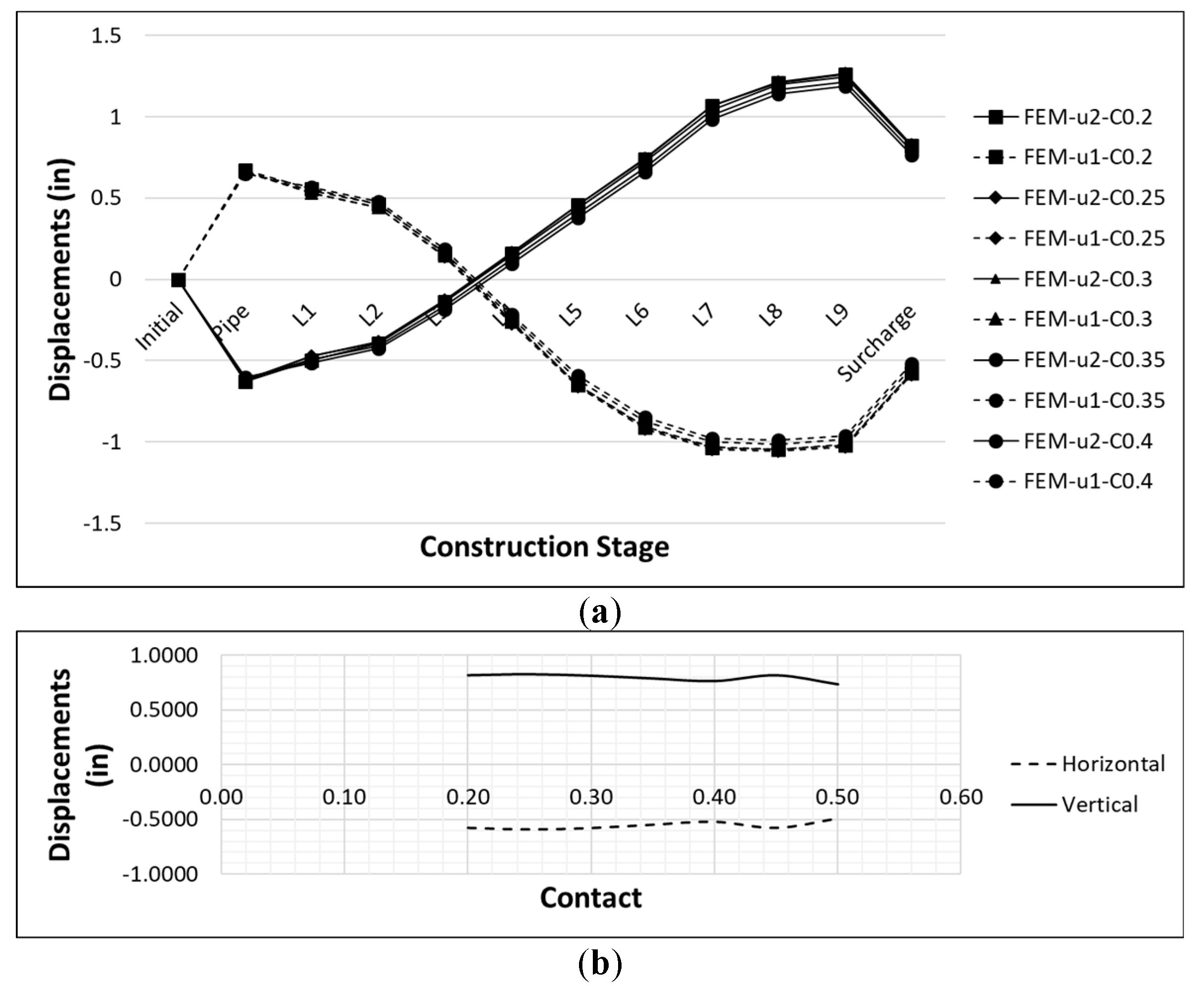
2.2.3. Contact
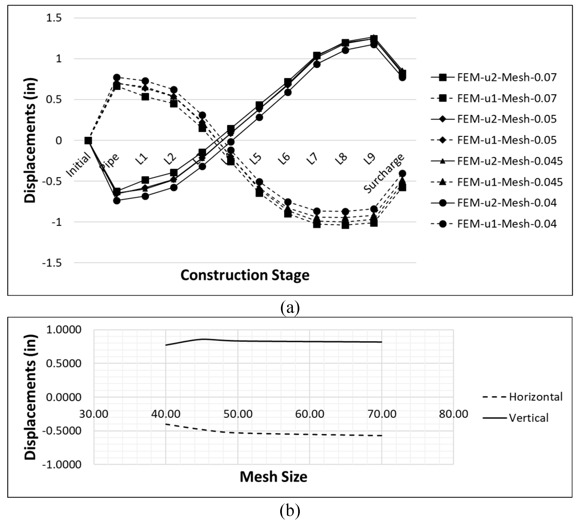
2.2.4. Mesh Size
2.3. Results of Validation of Model Finite Element
3. External Loads over Haul Roads
- is the equivalent area of the tire print on the trench. It is determined using the equivalent radius (which is half the width of the wheel);
- the width of the wheel is .
4. Parametric Study FEM Buried Pipe under Haul Road
4.1. Parametric Study
4.2. General Considerations
- It is considered that the contact walls of the trench are made of natural soil in order to more accurately estimate the behaviour of the pipe (see Figure 17). Additionally, it is considered that the trench walls do not require external control measures due to possible instability during its construction.
- For the calculation of the residual lateral pressure of the lateral backfill on the pipe, the stiffness of the trench is taken into account.
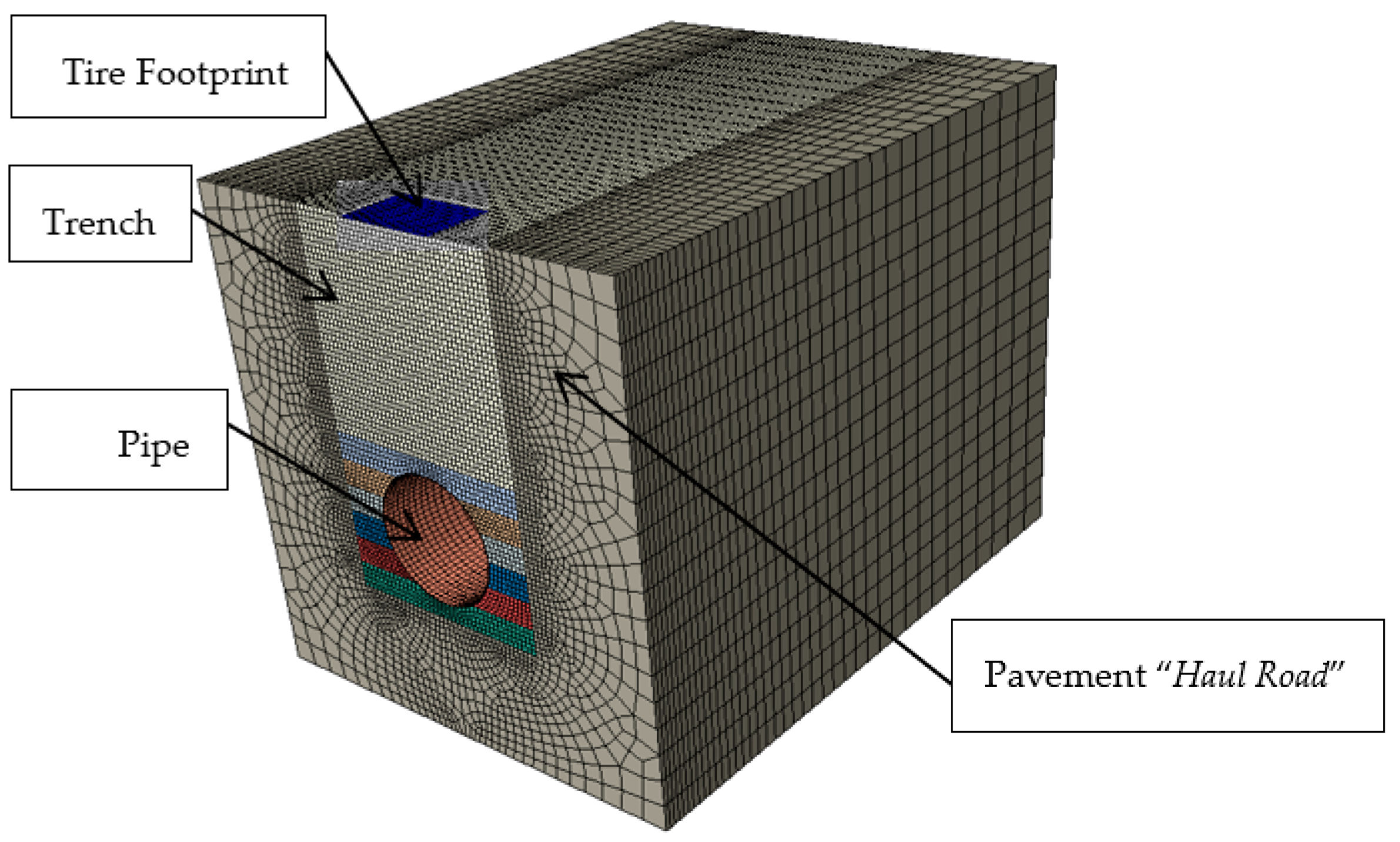
- The model considers longitudinal and transverse symmetry to reduce computational costs (see Figure 20).
- The surface load applied on the pipe is located in the central area of one of the rear wheel prints and the pipe is considered to be unaffected by the pressure of the front axle tire of the mining truck or the lateral rear wheel.
- According to the model boundary conditions, a restriction on the longitudinal displacement of the soil and the pipe is considered. A qualitative analysis of the effect of the model length on the variation in the vertical stress results produced by a surface load was carried out for model lengths of 3 m, 6 m, 9 m, 12 m and 15 m, for mesh sizes of 0.12 m. According to the results, it is concluded that the longer the pipe length, the less affected by this restriction are the results. Thus, for the parametric analysis, a model with a total length of 12 m and a minimum and maximum mesh density of 0.05 m and 0.5 m, respectively, was considered (longitudinal and transversal symmetrical model). Even when the results of vertical pressures on the pipe are slightly affected, the trends of stresses and deformations in the pipe will remain basically the same.
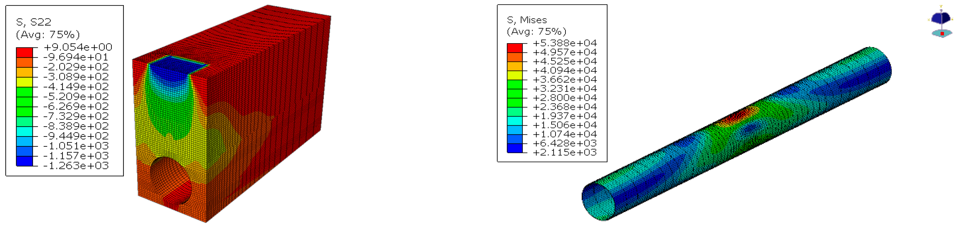
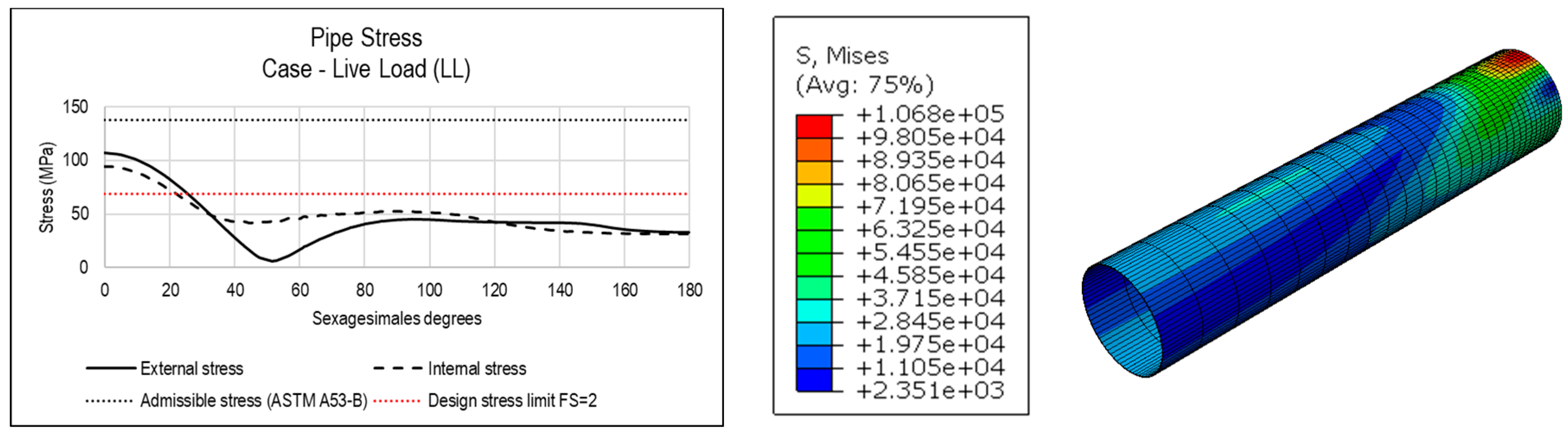
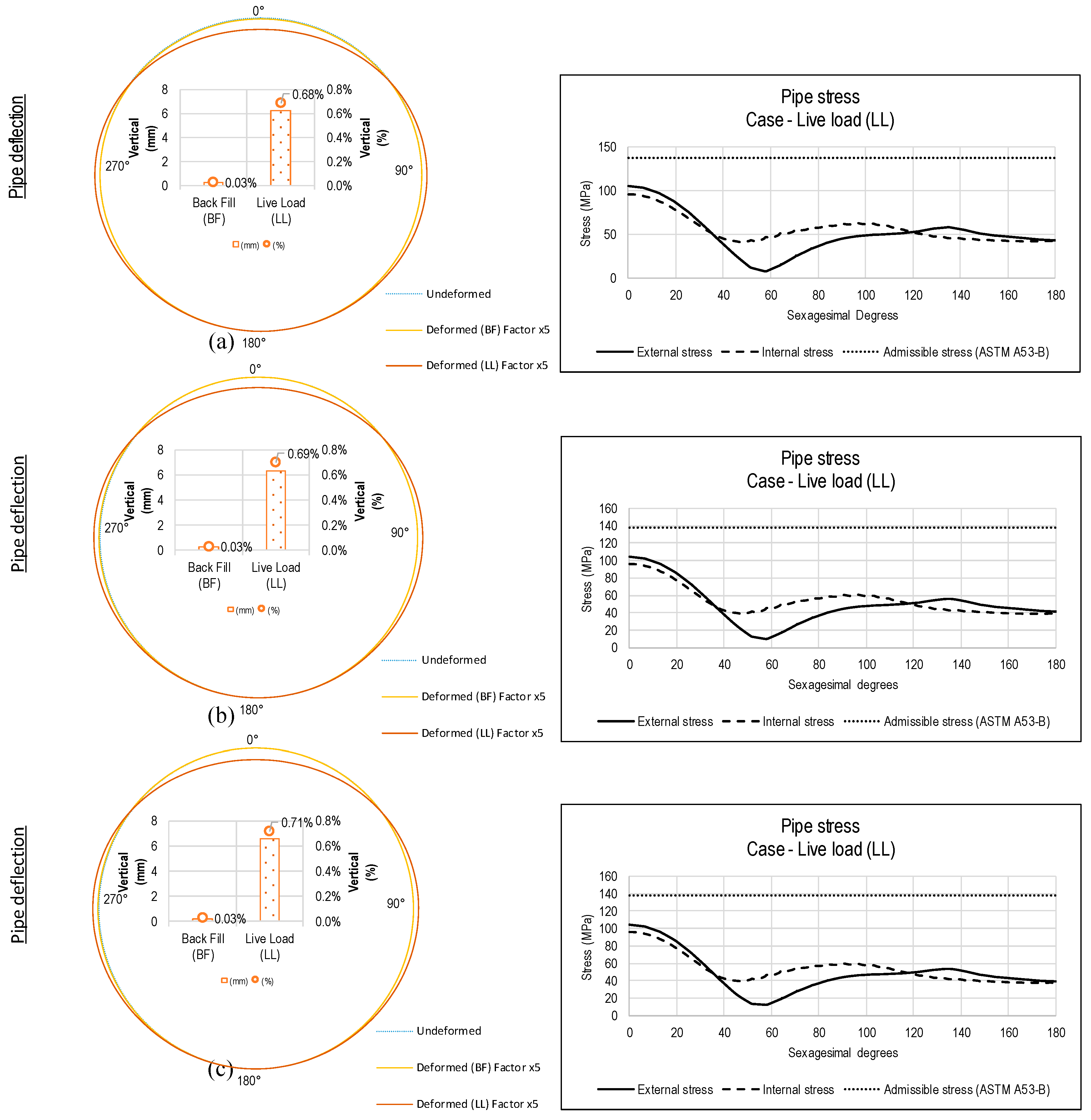
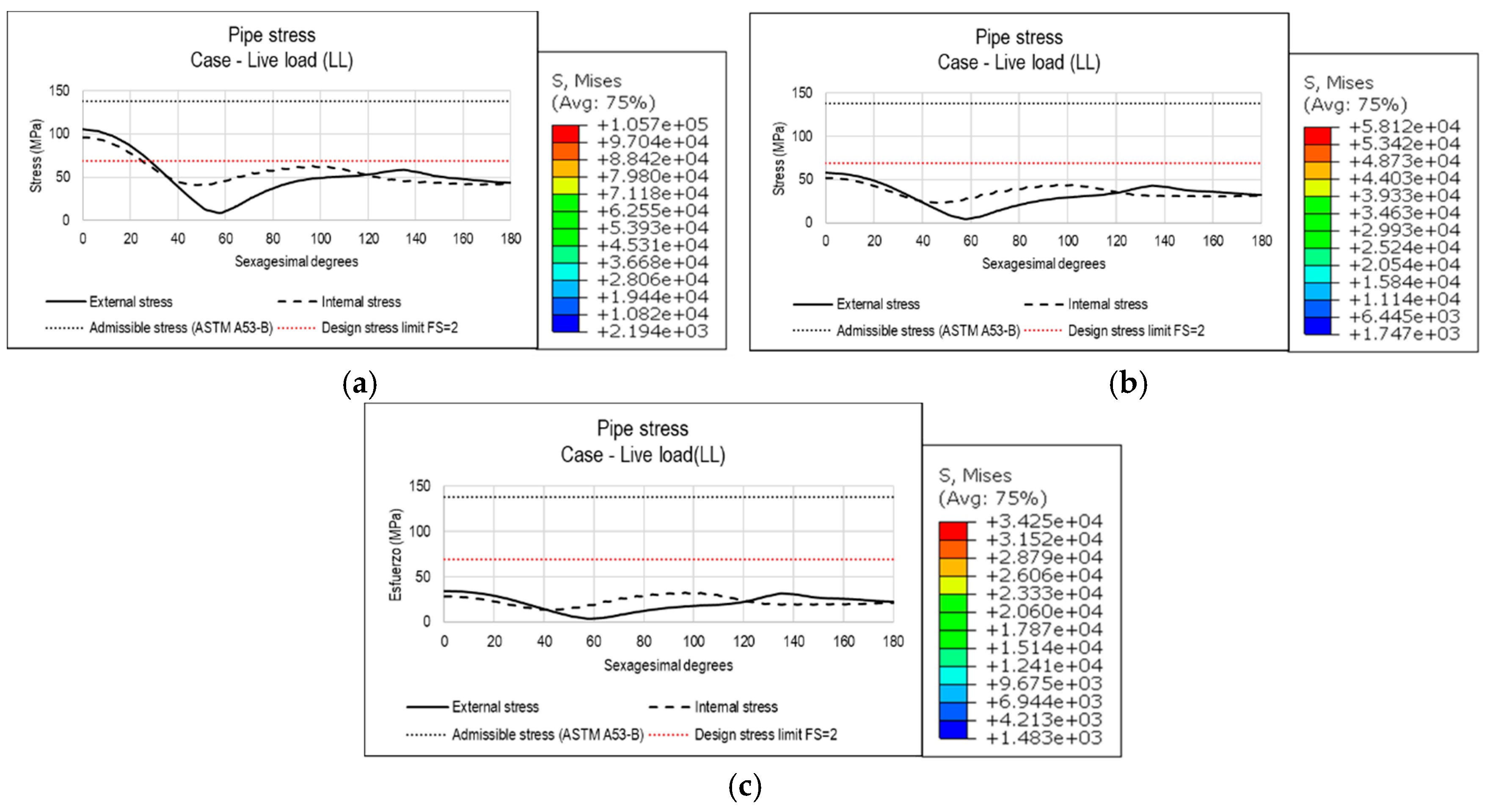
- To ensure that the pipe does not fail and to suggest design recommendations, the admissible stresses of the ASTM A53 Grade B material pipe will be considered in the analysis of the results.
4.3. Analysis of Results
4.3.1. Surface Pressure
4.3.2. Trench Width and Pipe Bedding Height
4.3.3. Lateral Backfill Material
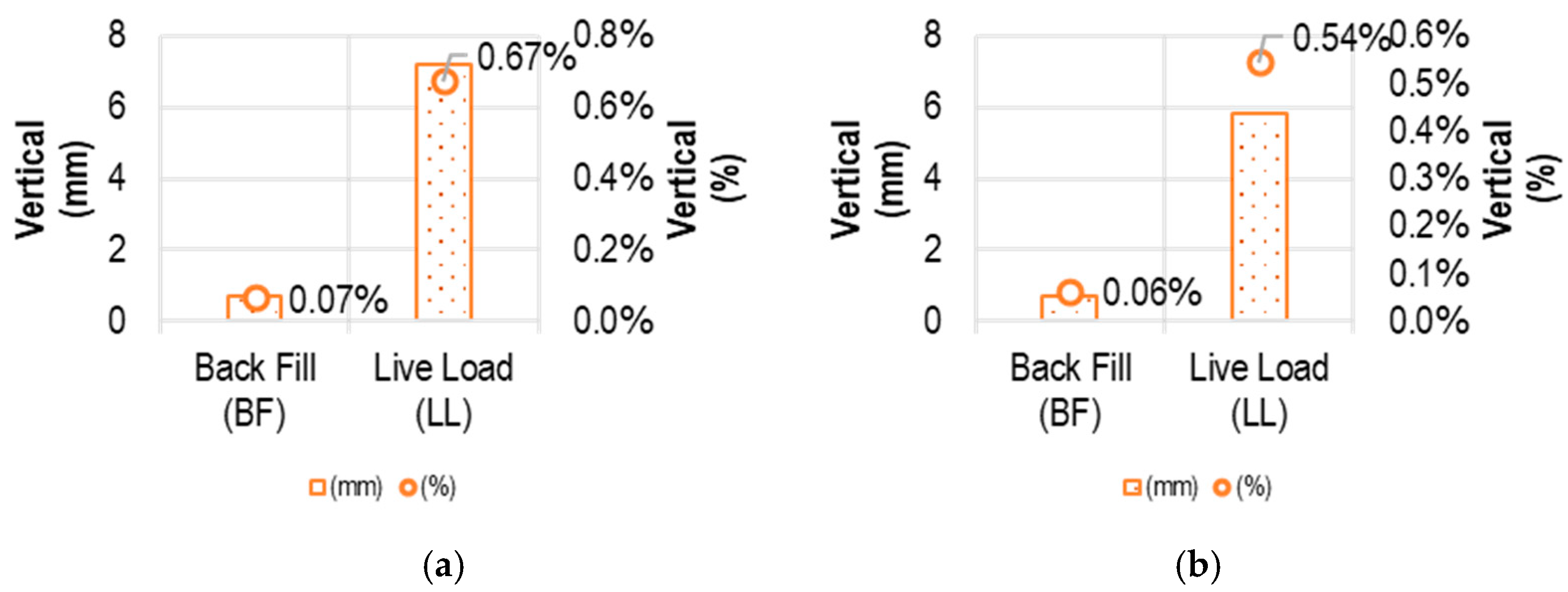
4.3.4. Backfill Height
4.4. Trends—Parametric Analysis
5. Conclusions
- A calculation procedure has been developed to analyse pipes buried under haulage roads bearing a surface pressure of 1250 kPa using the finite element method and taking into account the residual lateral pressure due to the compaction of the fill. The model has been validated with experimental data. Likewise, a sensitivity analysis has been carried out to evaluate the following variables: model length, mesh size, contact and residual lateral load.
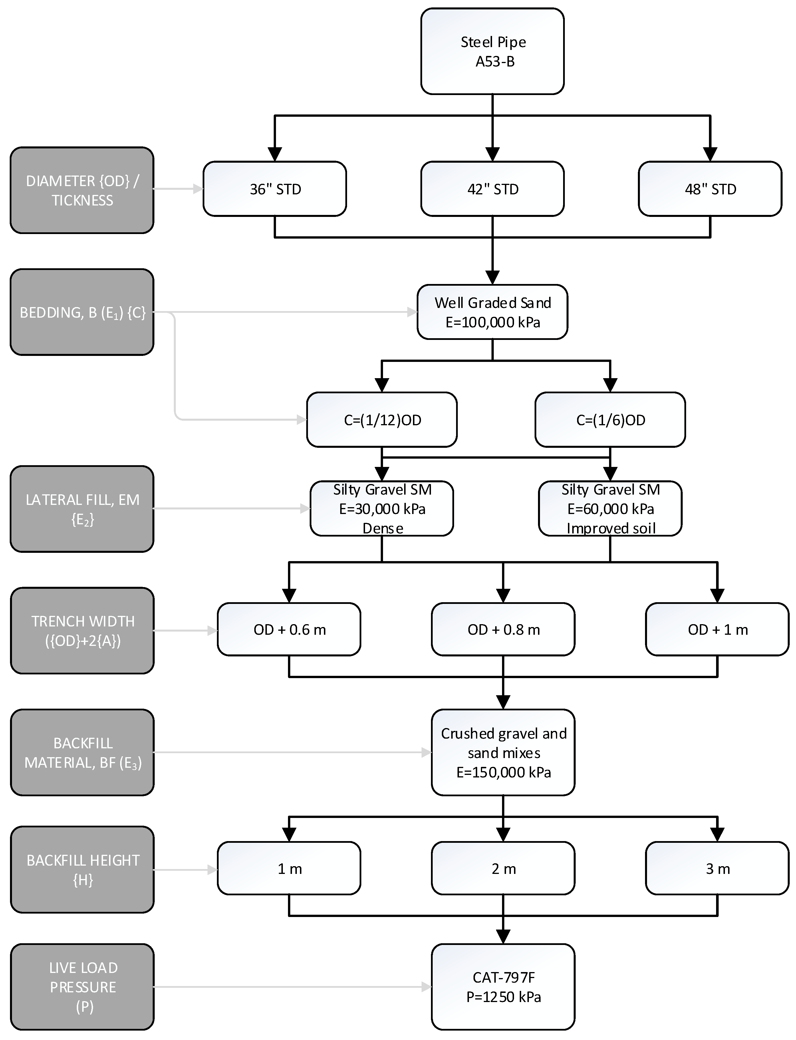
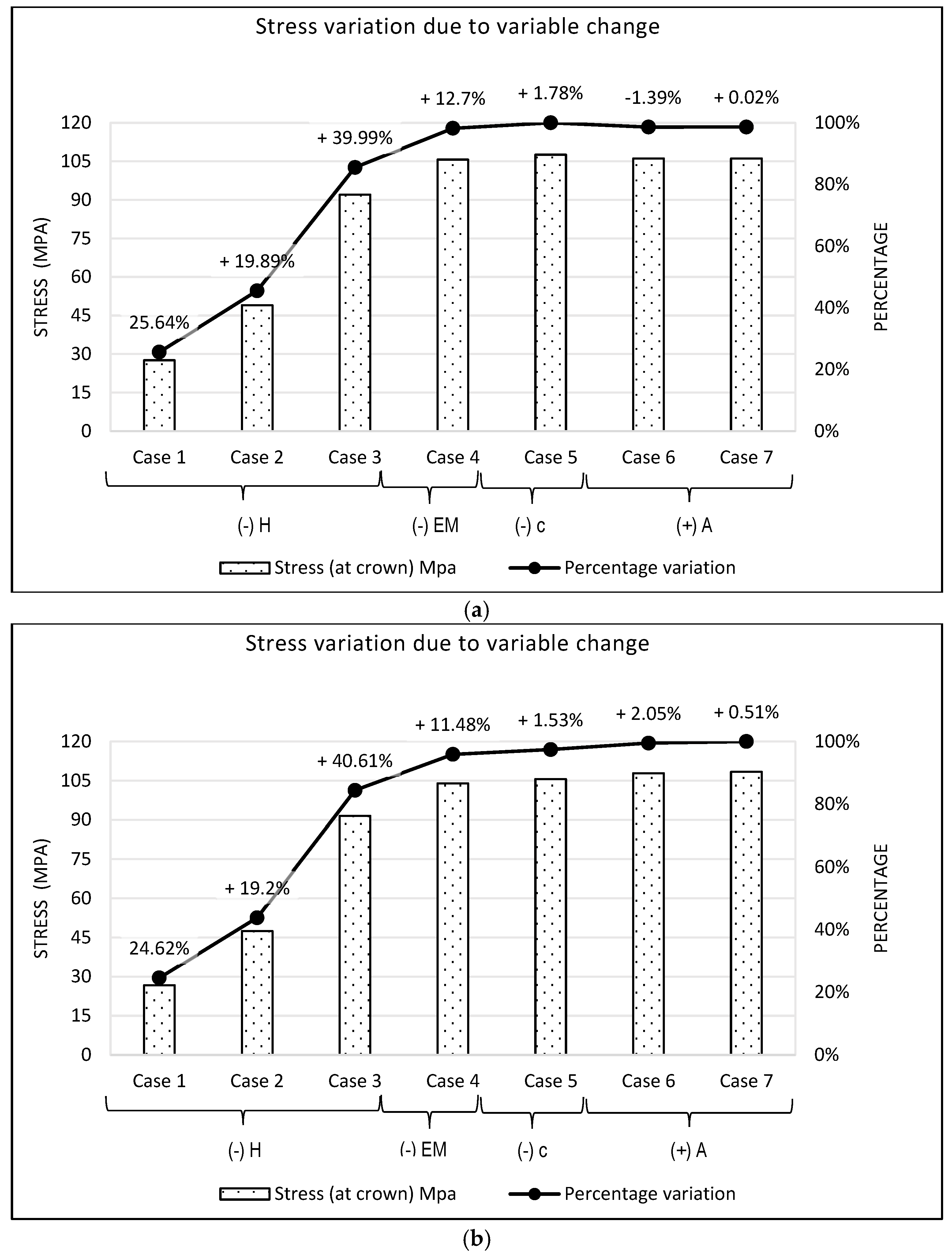
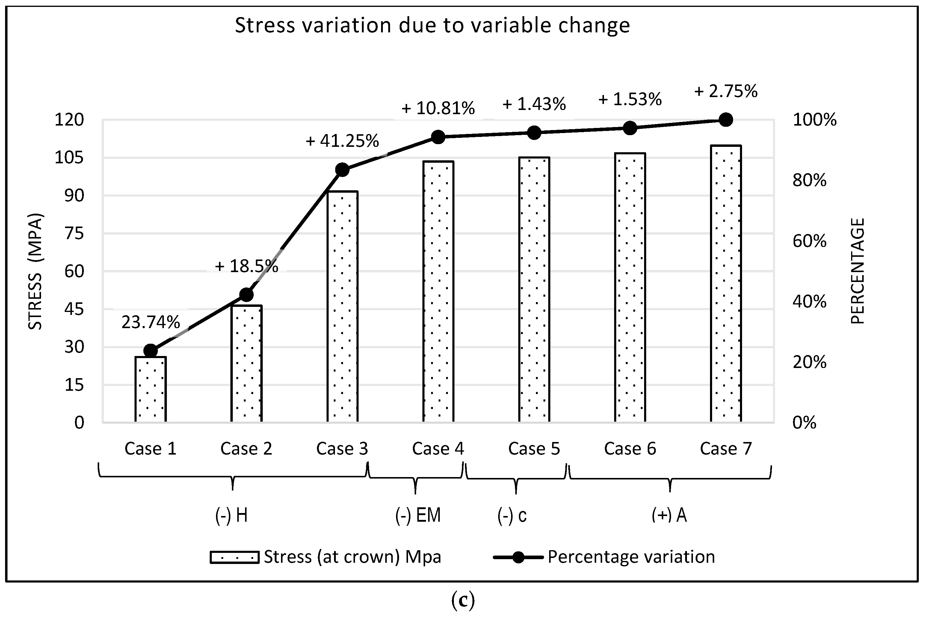
- A parametric study has been carried out with 108 models, varying the diameter of the pipe, the width and height of the trench, the height of the pipe bed and the type of lateral filling. The trend in the behaviour of the forces acting on the pipe when the selected variables are modified has been estimated. The results indicate that the most influential variables on the pipe deflection and stress are the height of the backfill and the elasticity modulus of the lateral fill.
- Changing the top fill height (H) from 3 m to 1 m increases stresses by approximately 60%. Likewise, changing the side fill material (EM) from 60,000 kPa to 30,000 kPa increases stresses by approximately 11%.
- Pipe bedding height (C) does not significantly affect stresses under mining truck loads. This variable is more important during the construction stage, where the higher the bed height (C) in the first installation stage, the better the pipe is supported, reducing initial deflections.
- The width of the trench does not significantly affect the stresses on the pipe. However, when the width increases, the results show that the stresses increase. Likewise, it is observed that if the width of the tire print is smaller than the pipe diameter, the efforts tend to increase; on the contrary, if the width of the tire print is greater than the pipe diameter, the efforts tend to be reduced.
- The variables that most influence installation costs are the height and width of the trench, along with the quality of the filling materials. The greater the trench height, the lower the stresses that the pipe bears, but on the other hand the excavation costs are higher. Likewise, the better the material quality with respect to the elasticity modulus, the lower the stresses that the pipe bears, but in the same way it increases the costs of the installation. Lastly, a reduction in the trench width implies both a reduction in stress on the pipe and a reduction in installation costs.
Author Contributions
Funding
Institutional Review Board Statement
Informed Consent Statement
Data Availability Statement
Conflicts of Interest
Nomenclature
| Horizontal pipe deflection (m) | |
| Outside pipe diameter (m) | |
| Buried pipe bedding constant | |
| α | Pipe bedding angle |
| Deflection lag factor (30% 40 years = 1.5) (1–1.5) | |
| Backfill load over pipe per pipe length unit (kN/m) | |
| External load over pipe per pipe length unit (kN/m) | |
| Mean radius of pipe shell (m) | |
| Pipe elasticity modulus (kPa) | |
| Transverse moment of inertia per length unit of pipe wall, ~ t3/12 (m3) | |
| t | Pipe thickness (m) |
| Modulus of soil reaction (kPa) | |
| Constrained Modulus (kPa) | |
| Backfill elasticity modulus (kPa) | |
| Poisson’s ratio of soil | |
| Impact factor | |
| Backfill height over pipe (m) | |
| Tire equivalent contact area (m2) | |
| Limit Bucking pressure (kPa) | |
| Water buoyancy factor | |
| Temperature variation | |
| Normal stress on the plane of soil failure | |
| Lateral stress of soil proportional to lateral fill cohesion (un-drained shear strength, Cu) | |
| Transversal area of soil layer (m2) | |
| Length of soil layer (m) | |
| Pipe young modulus x pipe thickness (kN/m) | |
| Lateral soil young modulus x Lateral soil length (kN/m) | |
| Lateral soil young modulus (kPa) | |
| Mohr–Coulomb yield function | |
| Friction angle | |
| Material cohesion | |
| Cu | Undrained cohesion |
| Tire contact length (m) | |
| Width contact, equivalent tire width (m) | |
| Equivalent radius | |
| Trench width | |
| Lateral fill elasticity modulus | |
| Pipe bedding height |
References
- AWWA M11. AWWA-M11 Steel Pipe-A Guide for Design and Installation; Edition, F(C); AWWA: Washington, DC, USA, 2017. [Google Scholar]
- AASHTO: American Association of State Highway and Transportation Officials. Standard Specifications for Highway Bridges, 17th ed.; AASHTO: Washington, DC, USA, 2002; ISBN 1560511710. [Google Scholar]
- Spangler, M.G. Underground Conduits—An Appraisal of Modern Research. Trans. Am. Soc. Civ. Eng. 1948, 113, 316–345. [Google Scholar] [CrossRef]
- Hartley, B.J.D.; Asce, A.M.; Duncan, J.M.; Asce, F. E’ and its variation with depth. J. Transp. Eng. 1988, 113, 538–553. [Google Scholar] [CrossRef]
- Krizek, R.J.; Parmelee, R.A.; Kay, J.; Elnaggar, H.A. Structural Analysis and Design of Pipe Culverts; NCHRP Report; NCHRP: Washington, DC, USA, 1971. [Google Scholar]
- Katona, M.G. Improved Methods for Simulating Live Loads for Two-Dimensional Structural Analysis of Buried Culverts. Transp. Res. Rec. J. Transp. Res. Board 2019, 2673, 036119811984646. [Google Scholar] [CrossRef]
- Warman, D.J.; Hart, J.D.; Francini, R.B. Final Report Development of a Pipeline Surface Loading Screening Process & Assessment of Surface Load Dispersing Methods; Kiefner & Associates, Inc.: Worthington, OH, USA, 2009; p. 75. [Google Scholar]
- Turner, M.J.; Clough, R.W.; Martin, H.C.; Topp, L.J. Stiffness and Deflection Analysis of Complex Structures. J. Aeronaut. Sci. 1956, 23, 805–823. [Google Scholar] [CrossRef]
- Wu, Y.; Li, J. Finite element analysis on mechanical behavior of semi-exposed pipeline subjected to debris flows. Eng. Fail. Anal. 2019, 105, 781–797. [Google Scholar] [CrossRef]
- Dezfooli, M.S.; Abolmaali, A.; Park, Y.; Razavi, M.; Bellaver, F. Staged Construction Modeling of Steel Pipes Buried in Controlled Low-Strength Material Using 3D Nonlinear Finite-Element Analysis. Int. J. Geomech. 2015, 15, 04014088. [Google Scholar] [CrossRef]
- Gálvez, D. Cálculo Estructural de Tuberías Enterradas por el Método de Elementos Finitos, con Base en el Informe Técnico Cen/Tr 1295-3 (Universidad Politécnica de Madrid). 2011. Available online: http://oa.upm.es/7753/1/DANIEL_GALVEZ_CRUZ.pdf (accessed on 24 October 2022).
- Liu, P.F.; Zheng, J.Y.; Zhang, B.J.; Shi, P. Failure analysis of natural gas buried X65 steel pipeline under deflection load using finite element method. Mater. Des. 2010, 31, 1384–1391. [Google Scholar] [CrossRef]
- Sharma, J.R.; Najafi, M.; Marshall, D.; Jain, A.; Rahjoo, S. Testing and Evaluation of Statically-Loaded Large Diameter Steel Pipe with Native Backfill Soils; ASCE Library: Lawrence, Kansas, 2011. [Google Scholar]
- Webb, M.C.; Trebicki DD, P.; Smulders, P.A. Field testing and buckling strength of buried large-diameter thin-walled steel pipes. Pipelines 2002-Beneath Our Feet: Challengers and Solutions. In Proceedings of the Pipeline Division Specialty Conference, Cleveland, OH, USA, 4–7 August 2002; p. 69. [Google Scholar] [CrossRef]
- Watkins, R.K.; Anderson, L.R. Structural Mechanics of Buried Pipes; CRC Press: Boca Raton, FL, USA, 2017. [Google Scholar] [CrossRef]
- Sharma, J.R. Development of a Model for Estimation of Buried Large Diameter Thin-Walled Steel Pipe Deflection due to External Loads; University of Texas at Arlington: Arlington, TX, USA, 2013. [Google Scholar]
- Li, Z.; Xu, L.; Wang, W. A method for vehicle–track–soil interaction analysis considering soil deformation. Arch. Civ. Mech. Eng. 2022, 22, 1–21. [Google Scholar] [CrossRef]
- Tian, Y.; Liu, H.; Jiang, X.; Yu, R. Analysis of stress and deformation of a positive buried pipe using the improved Spangler model. Soils Found. 2015, 55, 485–492. [Google Scholar] [CrossRef]
- Ai, Z.Y.; Cai, J.B. Static interaction analysis between a Timoshenko beam and layered soils by analytical layer element/boundary element method coupling. Appl. Math. Model. 2016, 40, 9485–9499. [Google Scholar] [CrossRef]
- Pilvin, P. Continuum Mechanics. In Mechanics-Microstructure-Corrosion Coupling; Elsevier: Amsterdam, The Netherlands, 2019; pp. 49–63. [Google Scholar] [CrossRef]
- Saberi, M.; Annan, C.D.; Konrad, J. On the mechanics and modeling of interfaces between granular soils and structural materials. Arch. Civ. Mech. Eng. 2018, 18, 1562–1579. [Google Scholar] [CrossRef]
- Drucker, D.C.; Prager, W. Soil mechanics and plastic analysis or limit design. Quart. Appl. Math. 1952, 10, 157–165. [Google Scholar] [CrossRef]
- Roscoe, K.H.; Schofield, A.N.; Thurairajah, A. Yielding of clays in states wetter than critical. Géotechnique 1963, 13, 211–240. [Google Scholar] [CrossRef]
- Roscoe, K.H.; Burland, J.B. On the generalized stress–Strain behavior of ‘wet clay. In Engineering Plasticity; Heyman, J., Leckie, F.A., Eds.; Cambridge University Press: Cambridge, UK, 1968; pp. 535–609. [Google Scholar]
- Duncan, J.M.; Byrne, P.; Wong, K.S.; Marby, P. Strength, Stress-Strain and Bulk Modulus Parameters for Finite Element Analysis of Stresses and Movements in Soil Masses; Rep. No. UCB/GT/801; University of California: Berkeley, CA, USA, 1980. [Google Scholar]
- Vermeer, P. A five constant model unifying well established concepts. In Constitutive Behavior of Soils; Balkema: Roterdam, The Netherlands, 1982; pp. 175–197. [Google Scholar]
- Schanz, T.; Vermeer, P.A.; Bonnier, P.G. The hardening soil model: Formulation and Verification. In Beyond 2000 in Computational Geotechnics–10 Years of PLAXIS; Balkema: Rotterdam, The Netherlands, 1999. [Google Scholar]
- Hsieh, P.G.; Ou, C.Y.; Lim, A. Use of the total stress un-drained model to the analysis of deep excavation. In Proceedings of the 17th Southeast Asian Geotechnical Conference, Taipei, Taiwan, 10–13 May 2010; Taipei International Convention Center: Taipei, Taiwan, 2010. [Google Scholar]
- Katona, M.G. Influence of Soil Models on Structural Performance of Buried Culverts. Int. J. Geomech. 2017, 17. [Google Scholar] [CrossRef]
- Clayton, C.R.I.; Symons, I.F. The pressure of compacted fill on retaining walls. Geotechnique 1992, 42, 127–130. [Google Scholar] [CrossRef]
- El Chazli, G. Experimental Investigation of Friction Factors in Horizontal Directional Drilling Installations. Master’s Thesis, University of Western Ontario, London, ON, Canada, 2005. [Google Scholar]
- Alam, S.; Alloinche, E.N.; Bartlett, C.; Sherpa, A.; Keil, B. Experimental Evaluation of Soil-Pipe Friction Coefficients. In Proceedings of the Pipeline Division Specialty Conference, Forth Worth, TX, USA, 23–26 June 2013; pp. 360–371. [Google Scholar]
- Abaqus. Analysis User’s Manual; (Version 6); Dassault Systemes Simulia, Inc.: Johnston, RI, USA, 2013; p. 11. [Google Scholar]
- Tannant, D.D.; Regensburg, B. Guide Lines for Mine Haul Road Design; Faculty of Engineering, School of Okanagan: Kelowna, BC, Canada, 2001. [Google Scholar] [CrossRef]
- Nehdi, M.L.; Mohamed, N.; Soliman, A.M. Investigation of Buried Full-Scale SFRC Pipes under Live Loads. Constr. Build. Mater. 2016, 102, 733–742. [Google Scholar] [CrossRef]
- Behroozinia, P.; Khaleghian, S.; Taheri, S.; Mirzaeifar, R. An investigation towards intelligent tyres using finite element analysis. Int. J. Pavement Eng. 2002, 21, 311–321. [Google Scholar] [CrossRef]
- Park, D.-W. Prediction of pavement fatigue and rutting life using different tire types. KSCE J. Civ. Eng. 2008, 12, 297–303. [Google Scholar] [CrossRef]
- Rao, G.V.; Dutta, R.K. Compressibility and strength behaviour of sand-tyre chip mixtures. Geotech. Geol. Eng. 2006, 24, 711–724. [Google Scholar] [CrossRef]
- Helwany, S. Applied Soil Mechanics: With ABAQUS Applications. In Applied Soil Mechanics: With ABAQUS Applications; John Wiley & Sons: Hoboken, NJ, USA, 2007. [Google Scholar] [CrossRef]
- ASME: American Society of Mechanical Engineers. ASME B36.10M Welded and Seamless Wrought Steel Pipe; ASME: New York, NY, USA, 2018; p. 32. [Google Scholar]
- Diab, Y.G. Mechanical method to evaluate safety factors in buried pipes. J. Transp. Eng. 1995, 121, 94–101. [Google Scholar] [CrossRef]
- Obrzud, R.F.; Truty, A. The Hardening Soil Model—A Practical Guidebook; Zace Services Ltd., Software Engineering: Preverenges, Switzerland, 2018; Volume 5, p. 205. [Google Scholar]


| Vehicles | Payload (t) | Rear Axle Side Wheels (kPa) |
|---|---|---|
| CATERPILLAR models 793 F (Irving, TX, USA) | 240 | 1242 |
| CATERPILLAR models 797 F | 400 | 1248 |
| KOMATSU model 930 E (Tokyo, Japan) | 297 | 1246 |
| KOMATSU model 980 E | 360 | 1236 |
| Material | Thickness (m) | Bearing Capacity (MPa) | Young’s Modulus (MPa) | |
|---|---|---|---|---|
| Surface | Gravel GW or crushed rock | 0.3 to 0.6 | 0.7 to 0.9 | Note 1 |
| Base | Gravel (GW) or pit run sand | 1 | 0.3 to 0.65 | 150 to 350 |
| Subbase | Gravel (GW) or till, mine spoil | 1.5 | 0.1 to 0.2 | 100 to 150 |
| Vehicle Description | Weight | % Axle Load | Tire Dimensions | Gross Weight | ||||
|---|---|---|---|---|---|---|---|---|
| Chassis (+) Other | Hopper Loading (Payload) | Single Front | Double Rear | Type | Weight | Width | ||
| (kg) | (kg) | (%) | (%) | (kg) | (m) | (kg) | ||
| CATERPILLAR model 793 F | 120,000 | 235,000 | 33 | 66.7 | 40.00R57 | 3850 | 1.107 | 378,101 |
| CATERPILLAR model 797 F | 220,000 | 360,000 | 33 | 66.7 | 59/80R63 | 5371 | 1.458 | 612,223 |
| KOMATSU model 930 E | 174,815 | 297,000 | 33 | 66.7 | 53/80R63 | 4536 | 1.311 | 499,031 |
| KOMATSU model 980 E | 214,137 | 360,000 | 33 | 66.7 | 59/80R63 | 5371 | 1.458 | 606,360 |
| Vehicle Description | Contact Area per Wheel | Loads | Pressure | |||||||
|---|---|---|---|---|---|---|---|---|---|---|
| re | ac | A′ | L | Rear Axle | Side Wheels | Side Wheel Area | Rear Axle/Side Wheels | Impact Factor | Rear Axle Side Wheels | |
| (m) | (m2) | (m) | (m) | (kg) | (kg) | (m2) | (kPa) | - | (kPa) | |
| CATERPILLAR model 793 F | 0.5535 | 0.96 | 1.107 | 0.9 | 252,193 | 126,097 | 1.9926 | 621 | 2 | 1242 |
| CATERPILLAR model 797 F | 0.729 | 1.67 | 1.458 | 1.1 | 408,353 | 204,176 | 3.2076 | 624 | 2 | 1248 |
| KOMATSU model 930 E | 0.6555 | 1.35 | 1.311 | 1 | 332,854 | 166,427 | 2.622 | 623 | 2 | 1246 |
| KOMATSU model 980 E | 0.729 | 1.67 | 1.458 | 1.1 | 404,442 | 202,221 | 3.2076 | 618 | 2 | 1236 |
| Soil Type | Compaction | Elasticity Modulus | Density | Friction Angle | Cohesion | |
|---|---|---|---|---|---|---|
| USCS | Proctor | Es (2) (kPa) | ρ (t/m3) | Φ (°) | c (kPa) | |
| Haul Road (TN) | GW | - | 150,000 | 2 | 42 | 0 |
| Bedding (B) | SW | 95% | 100,000 | 2.25 | 48 | 0 |
| Embedment (EM) (1) | SM | 80% | 30,000 | 1.71 | 28 | 17 |
| SM | 90% | 60,000 | 1.92 | 32 | 24 | |
| Backfill (BF) | GM | 95% | 150,000 | 2 | 42 | 0 |
Disclaimer/Publisher’s Note: The statements, opinions and data contained in all publications are solely those of the individual author(s) and contributor(s) and not of MDPI and/or the editor(s). MDPI and/or the editor(s) disclaim responsibility for any injury to people or property resulting from any ideas, methods, instructions or products referred to in the content. |
© 2023 by the authors. Licensee MDPI, Basel, Switzerland. This article is an open access article distributed under the terms and conditions of the Creative Commons Attribution (CC BY) license (https://creativecommons.org/licenses/by/4.0/).
Share and Cite
Vilca, N.S.; Gómez-Amador, A.M.; Jiménez de Cisneros Fonfría, J.J. Soil–Structure Interaction Analysis Using the Finite Element Method in Thin-Walled Steel Pipes Buried under Haul Roads. Appl. Sci. 2024, 14, 167. https://doi.org/10.3390/app14010167
Vilca NS, Gómez-Amador AM, Jiménez de Cisneros Fonfría JJ. Soil–Structure Interaction Analysis Using the Finite Element Method in Thin-Walled Steel Pipes Buried under Haul Roads. Applied Sciences. 2024; 14(1):167. https://doi.org/10.3390/app14010167
Chicago/Turabian StyleVilca, Nicher Saul, Ana María Gómez-Amador, and Juan José Jiménez de Cisneros Fonfría. 2024. "Soil–Structure Interaction Analysis Using the Finite Element Method in Thin-Walled Steel Pipes Buried under Haul Roads" Applied Sciences 14, no. 1: 167. https://doi.org/10.3390/app14010167
APA StyleVilca, N. S., Gómez-Amador, A. M., & Jiménez de Cisneros Fonfría, J. J. (2024). Soil–Structure Interaction Analysis Using the Finite Element Method in Thin-Walled Steel Pipes Buried under Haul Roads. Applied Sciences, 14(1), 167. https://doi.org/10.3390/app14010167