Abstract
Aiming at the deficiencies of the traction helical gear transmission system when the EMU is running at high speed, this paper proposes and designs a kind of arc toothed cylindrical gear adapted to the traction of higher speed EMU. A parametric arc toothed cylindrical gear model was constructed using CREO, and its dynamic contact characteristics and acoustic response characteristics were analyzed under sustained operating conditions using the finite element boundary element method. The design of a tooth profile combined with the radius of the arc toothed line of the comprehensive trimming program put forward a virtual trimming prototype method through MATLAB and CREO reconstruction gear, and trimming before and after the gear transmission simulation experiments occurred for comparison and analysis. This study shows that the traction arc toothed cylindrical gear comprehensive modification method proposed in this study achieves better dynamic performance optimization, effectively reduces the contact stress and radiation noise of the gear transmission, and provides a theoretical basis for the development of a new generation of high-speed EMU stock traction drive systems.
1. Introduction
At the beginning of 2021, Beijing China State Railway Group Co., Ltd. (Beijing, China) put forward the “CR450 Science and Technology Innovation Project Implementation Plan”, which officially launched the CR450 (maximum speed of 450 km/h, sustained speed of 400 km/h) science and technology innovation project, focusing on high-speed EMU system integration, axle drive, braking control, vibration and noise reduction, and other core technologies [1]. A high-speed EMU stock traction gear is the core component of the train’s power drive, but it is also one of the primary sources of noise caused by vehicle noise [2]. Currently, existing EMU stock commonly uses helical gear drive systems. However, with long periods of high-load operation, gearbox bearings can develop severe pitting and blackening, which is mainly caused by high oil temperatures. At the same time, gearboxes suffer from other problems, such as seal failure, reduced lubrication, increased gear noise, and shorter service life. Speed is the eternal goal of transportation, and noise is the primary factor limiting higher operating speeds [3]. At present, many countries and organizations have taken in-vehicle noise as an important indicator for measuring the comfort of high-speed rail. Zhang et al. tested the radiation characteristics of the noise in the sightseeing area of the train compartment at a speed of 350–400 km/h, and the results showed that the noise value in the compartment ranged from 93 to 98 dB, and increased roughly linearly with the increase in speed [4]. Hearing impairment studies have shown that the human ear can be impaired by prolonged exposure to noise levels above 80 dB [5]. Therefore, it is necessary to effectively reduce the noise of high-speed train gears. The study of traction gears and their noise reduction and modification programs adapted to the new generation of EMU have become a key issue that needs to be addressed urgently.
Gear contact analysis is a commonly used method for gear optimization. Ma et al. established a dynamic finite element model of the gear meshing contact impact with a circular arc-toothed line cylindrical gear as the research object and analyzed the relationship between velocity, position, combined force, and time during the impact process. It was found that the velocity and position during impact have a significant influence on the tooth contact characteristics [6]. Zhang et al. established an explicit mathematical model between the design parameters and contact stress of cylindrical gears with arc teeth and used the whale optimization algorithm to change the function parameters to optimize and analyze the effect of design parameters on the contact stress of cylindrical gears with circular arc teeth [7]. Tang et al. used the helical gear of a CRH380A high-speed train as the research object, synthesized Pro/E and ANSYS Workbench, and deeply analyzed its meshing characteristics and performance. The dynamic contact stress state is revealed through modeling and finite element simulation, providing substantial guidance for gear strength calculations [8].
The main causes of vibration in gear structures include gear–tooth interaction, unbalanced loads, material quality, resonance effects, and tooth wear. These factors interact to cause vibration problems. Appropriate design and manufacturing measures are required to minimize vibration. Gear shaping is a method of improving gear transmission performance by adjusting the tooth shape of the gear. Potential benefits of gear reshaping include noise reduction, increased gearing efficiency, improved load distribution in gears, and reduced vibration levels.
In terms of the design of gear trimming programs, scholars have used different methods to verify the effectiveness of the trimming design. For example, Zhang et al. studied a two-stage star gear transmission system and successfully reduced the system vibration through tooth profile modification and dynamic modeling [9]. Gao et al. proposed a dynamic optimization trimming technique for enhancing the dynamic characteristics of gear transmissions, and this method combines the dynamic load factor [10]. Hao et al. showed that the optimal gear trim has a significant effect on the dynamic characteristics, especially when differences in tooth shape and profile trim are considered [11]. Tang et al. use theory, numerical simulation, and optimization design to analyze the effect of gear trimming on transmission noise of CRH380A EMU stock through finite element simulation and neural network and finally realize low noise design [12]. In Deng et al.’s work, on the other hand, gears were reshaped by modifying the radius of the blade and the shape of the blade, which could improve the dynamic characteristics of the gears [13]. Feng et al. used the envelope method to spread these into orthogonal arc-toothed gears; the outer diameter of the gears increased after trimming, and the phenomenon of the tooth apex becoming pointed was changed, which provided a basis for further study of the bias load characteristics [14]. Yan et al. investigated the effect of gear tooth shaping on dynamic meshing contact stresses, and the results showed that shaping can significantly reduce the maximum contact stresses, which is expected to improve the life of gearboxes [15]. Zhang et al. researched the tooth bias loading problem of helical gears, using theoretical calculations and parameter optimization design methods to specify the optimal combination of trimming volume. The results show a 58.2% reduction in maximum tooth load, improving system performance [16].Wang et al.’s study introduced a method to solve the problem of gear transmission vibration, noise, and load unevenness, based on helical gear mesh contact analysis, established a multi-objective helical gear optimization trimming method, and achieved significant improvement [17].In addition, some studies have focused on the effect of trimming on the contact stresses, fatigue life, and transmission errors of gears [18,19].
In addition, for the virtual prototype reconstruction method of trimmed gears, the scholars concerned used different software and techniques to build the trimmed gear model and compared them by optimizing the target parameters. This helps to validate the reduction in transfer error after trimming, as well as other performance improvements [20,21,22,23,24]. These studies provide the theoretical basis and practical application support for gear reshaping and provide a powerful tool for improving the performance of gear transmission systems.
Today’s literature focuses on simple tooth shapes and flank designs, such as schemes for trimming helical gears. However, in terms of virtual prototyping for reconstructing modified gears, the existing commercial software (e.g., Romax 18) only supports the reconstruction function of traditional helical gears and spur gears, but does not cover complex curved gears such as curved cylindrical gears, which limits its application scope to a certain extent. At the same time, the method of constructing a topologically modified gear model is relatively complex and difficult; thus, the topological modification method has some limitations in improving the performance of gears [25,26]. In order to solve the above problems, this paper proposes a method using MATLAB and CREO that can quickly and accurately reconstruct the model of a modified arc-toothed cylindrical gear. This new approach has significant advantages over the existing methods. First, this method is applicable to a wider variety of gears and is no longer limited to traditional helical or spur gears. Secondly, this method greatly simplifies the design process of trimmed gears and improves the design efficiency. In addition, this paper also designs a comprehensive profile trimming scheme for tooth profiles combined with the radius of a curved-tooth line, which has a wider scope of application compared with the existing gear trimming software. In summary, this approach not only addresses the limitations of existing methods but also provides significant improvements in design efficiency and performance improvement. This innovative approach and comprehensive reshaping program provide a reference for the field of reshaping gear design.
Traction arc cylindrical gears for high-speed EMU stock offer unique performance advantages in transmission, including the high efficiency of helical gears, good lubrication properties, no additional axial component forces, low error sensitivity, and excellent transmission efficiency. This type of gear has been widely used in high-speed naval helicopters, high-power and high-rpm aero-engines, etc. [27]. In this paper, we exploratively propose a traction arc-toothed cylindrical gear system adapted to the new generation of high-speed EMU, construct a parametric gear transmission model through CREO, and analyze its dynamic contact characteristics and acoustic response characteristics under the sustained working conditions of high-speed EMU by using the finite element–boundary element method. We also design a tooth profile combined with the radius of the arc-toothed line comprehensive trimming program and propose a method to reconstruct the virtual trimming prototype of gears through MATLAB and CREO. This approach allows for a more efficient and faster reconstruction of virtual trimming prototypes of gears. Finally, the dynamic contact characteristics of the meshing and noise reduction optimization of the modified arc-toothed cylindrical gears are verified and compared. This work provides a theoretical basis and practical application prospects for the design of the traction drive system of the new generation of high-speed EMUs, as well as a more comprehensive optimization solution for the traction drive performance of high-speed EMUs.
2. Traction Arc-Toothed Cylindrical Gear Three-Dimensional Modeling
With reference to the relevant parameters of the G301 traction gear transmission system configured for high-speed EMU CRH380A, the coefficients of normal modulus, number of teeth, pressure angle, gear width, radius of arc-toothed line, height of the top of the tooth, and backlash of the top of the tooth of the new-generation high-speed EMU traction arc gear were initially designed, as shown in Table 1.

Table 1.
Design parameters for traction arc cylindrical gear units.
With the CREO parametric design function, the parameters can be quickly modified such that the desired 3D solid model can be updated immediately. By entering the geometric equation for the gear in the CREO “Relationships” dialog box [28], a series of circles and helixes for the gear can be drawn according to the basic parametric relationships in Table 1 and correlated with the relationship equation. The involute curve of the gear is generated by using the parametric equation of the involute curve in the Cartesian coordinate system (Equation (1)) [12], and the gear model is generated via feature operations such as a scanning hybrid array. Finally, the assembly constraint relationship between the two gears was defined, and their assembly model was established, as shown in Figure 1. With this method, gear design can be carried out efficiently, and the parameters can be flexibly adjusted to meet different requirements. In addition, parametric design provides the ability to quickly build the subsequent reconfiguration of trimmed gears, greatly improving the design efficiency.
where is the radius of the base circle and is the roll angle of the involute generating line on the base circle, which takes the value of .
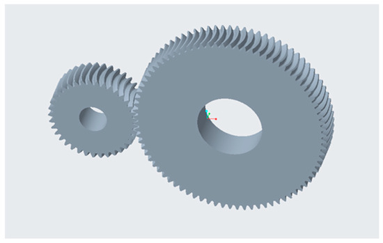
Figure 1.
Model of curved-tooth cylindrical gear unit.
3. Dynamic Contact Analysis of Traction Arc-Toothed Cylindrical Gear Units
The gear meshing model constructed in the CREO 5.0 software was imported into Workbench to establish a finite element model, and dynamic contact analysis was carried out on the model from the perspective of dynamics to obtain the dynamic contact characteristics of the curved-tooth cylindrical gear.
3.1. Theory of Contact Stresses on Gear Surfaces
Theoretically, gears work when a load is transmitted by line contact, taking into account the elastic deformation of the contact; in fact, it is a small surface contact, according to Hertz’s theory [29]; thus, the maximum contact stress generated when the gears come into contact during meshing is as follows:
where is the normal pressure of the gear pair, is the length of the contact line, is the integrated curvature of the contact point, and are the Poisson’s ratios of the two gear materials, and and are the moduli of elasticity of the two gear materials.
3.2. Imposition of Boundary Conditions and Post-Processing
Transient dynamics are suitable for modeling and analyzing objects subjected to external loads or impacts over time. Solving transient dynamic problems is much more complex than solving hydrostatic equations, and the computational time can increase considerably. Therefore, to accurately solve the dynamic problem, it is necessary to rationally choose the parameters and impose the boundary conditions.
- Defining materials
The strength and durability characteristics of the material directly affect the life and reliability of the gear system. Different materials have different strength and fatigue properties; thus, choosing the right material is essential to ensure that the gear system can withstand the loads it is subjected to. We referred to the current G301 high-speed EMU stock traction gear material and defined the material properties of the curved-tooth cylindrical gear in the Workbench as shown in Table 2.
Table 2.
Material parameters of radial cylindrical gear units.
Using the association function of CREO and ANSYS Workbench, a 3D model of the gear pair built in CREO was imported into the transient dynamics plate of ANSYS Workbench to establish the finite element model.
- 2.
- Gear finite element model meshing
The sparseness, quality, and quantity of the meshing of the finite element model directly affect the accuracy of the analysis results and the elastic deformation of the gear tooth top. Too many grids can greatly increase the speed of computer calculations, and too few grids can lead to inaccurate results. The reason is that when the number of meshes is too large, the size of each element is small, and the system needs to calculate the interactions between a large number of small elements, which may lead to slower computer calculations. On the contrary, when the number of meshes is too small, the element sizes are larger, and the system gives a coarser approximation of the object. This can lead to inaccurate calculations as it does not capture the detailed features and stress changes in the object. Therefore, meshing is one of the most critical steps. Gear contact areas are places of high stress. In this region, the meshing between the gear teeth induces a concentration of high stresses, and a more detailed mesh is required in order to capture the microscopic changes in the load distribution and stress distribution. By encrypting the gear contact area with a high density, the accuracy of the results can be improved, especially for the evaluation of localized stresses and deformations. As long as the error is within the allowable range, it is sufficient to take localized encryption in the part of the gear meshing contact area, and the part of the mesh outside the contact area can be automatically divided by the system. Since curved cylindrical gears usually have complex curved surfaces and geometrical features, tetrahedral meshes provide better geometrical adaptability and are able to delineate these irregular shapes more flexibly to accommodate the curves and surfaces of the gears. Tetrahedral meshes typically have high computational accuracy in capturing complex geometries and curved surfaces. This is important for stress analysis and performance simulation of curved cylindrical gears, and mesh independent validation of the model. Initially, the mesh size is automatically divided, and then the mesh of the high-stress region is encrypted several times, and the difference between the two stress results when the final mesh is 3 mm is less than 5%, i.e., the mesh of the local region has already reached convergence, the mesh of the local region has been sufficiently refined, and the results are insensitive with respect to the change in the mesh [30]. The use of adaptive mesh encryption optimizes the fineness of the critical regions of the simulation, saves computational resources, and produces more accurate simulation results. The maximum encryption cycle defaults to 1, and the encryption depth is 2. The division results in the number of nodes is 240,162, the number of cells is 138,173, and the size of the encrypted portion of the grid is 3 mm. The delineated grid is shown in Figure 2.
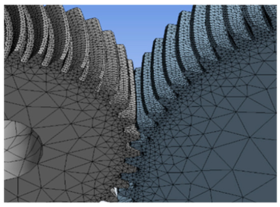
Figure 2.
Delineation of the grid.
- 3.
- Setting up contact and connection subs
The pinion tooth surface is the target surface, and the large gear tooth surface is the contact surface, named “A” and “B”, respectively. The type of contact pair is set to “Frictional” since there will be relative sliding between the tooth surfaces. The coefficient of friction is a parameter that describes the amount of friction between two surfaces when they are moving relative to each other, and the coefficient of friction is set to 0.15. In actual systems, gears usually adjust their position automatically during normal operation to ensure that the teeth are in contact; thus, the initial contact state is set to “Adjust to Touch”. FKN specifies a scale factor or a true value for the contact stiffness. In general, FKN is taken as 0.01 or 0.1 for softer solid contact and 1.0 for large solid contact. Therefore, the normal stiffness FKN is set to 1.
Two connection areas are inserted in the Connection menu; the type is selected as Rotation of Body-Ground for both, and the range is selected as the face of the shaft holes of the two gears.
- 4.
- Definition of gear pair load conditions
Based on the specific design conditions of the new generation of high-speed EMU, the rotational speed is applied to the main wheel (pinion gear), and the torque is applied to the driven wheel (large gear) under continuous operation conditions. The speed and torque of the model are presented in Table 3.
Table 3.
Continuous operation loads.
- 5.
- Applying gear constraints and setting step parameters
By applying rotational speeds and moments, the motion of the gear pair is simulated as realistically as possible. The connecting pair is added to the transient menu according to the working condition parameters in Table 3, the rotational speed is selected as the type of the first connecting pair, and the range is set to the face of the shaft hole on the main wheel. At the same time, torque is selected as the type of the second connecting pair and the range is set to the face of the shaft hole of the driven wheel. It must be ensured that the direction of the torque is the same as the direction of the rotational speed of the main wheel.
Through the dynamic simulation, this paper sets both the speed and torque to increase gradually from 0 to a constant value within 0.005 s. Due to the computationally intensive gear power contact simulation and analysis in ANSYS Workbench, the simulation does not need to consider the process of rotating the gear for a week by rotating a number of teeth. Now, with a constant value of 0.009 s, a meshing cycle of 0.009 s is set to simulate the dynamic meshing process of the gearing system from stationary to startup and then to continuous working conditions. Using the number of sub-steps as a unit set, the initial number of steps is set to 50, the minimum sub-steps 25, the maximum sub-steps 500, the time step control is automatic leveling, the interface processing is to adjust the contact, and all other defaults are program control.
- 6.
- Simulation results and analysis.
Equivalent forces and contact tools must be inserted into the post-processing of simulation results. Then, the pressure in the contact tool is selected, and the simulation is solved according to Equation (2). The results of force convergence analysis show that the calculations are accurate and reliable in the nonlinear case. In Figure 3b, it can be seen that the stress distribution at the root of the gear tooth during meshing is in red color, which indicates that the stress received here is the highest, and the root of the gear tooth is usually the narrowest part of the tooth groove, which results in a small cross-sectional area of the material at the root of the tooth. As a result, the stresses experienced at the root of the tooth are usually higher.
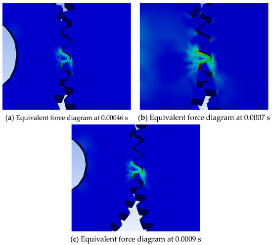
Figure 3.
Mises stress cloud for gear contact under startup condition.
With the calculated equivalent stress and equivalent strain data, the stress–strain curves of the traction arc-toothed cylindrical gear pair in the working process are plotted as shown in Figure 4.
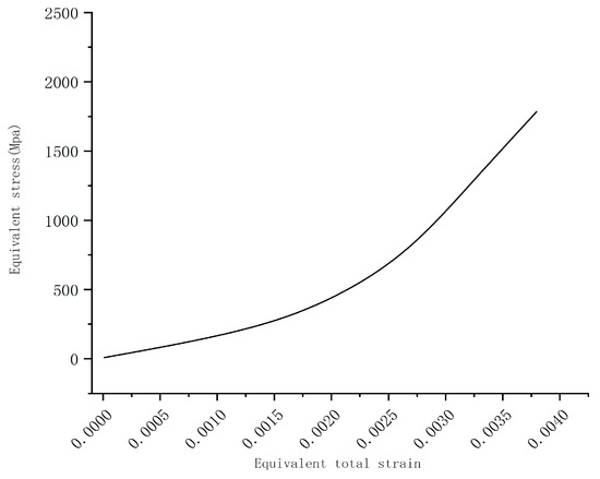
Figure 4.
Stress–strain curve.
Figure 5 shows the contact pressure distribution at different moments of a cycle under continuous operating conditions. Figure 5c shows the contact pressure distribution at the moment of engagement when the contact pressure was the largest, and the contact pressure was 2559.7 MPa. The force points were evenly distributed on the tooth surface, and the contact area was elliptical, with the greatest force at the center. A more accurate model is illustrated based on the characteristics of the curved cylindrical gears.
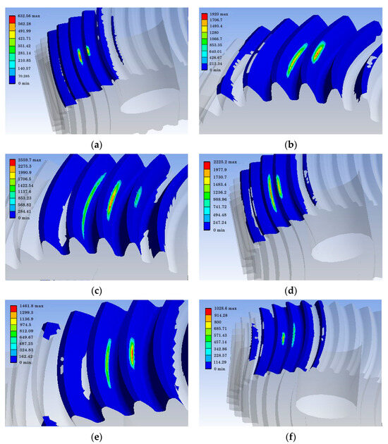
Figure 5.
Maximum contact pressure distribution of the gear pair at different moments under continuous operating conditions. (a–f) show the meshing at different moments in a cycle.
The maximum contact pressure data for the meshing position of the gear pair under continuous operating conditions are listed in Table 4.
Table 4.
Maximum contact stress at different moments under continuous gear conditions (MPa).
In order to ensure the reliability of the simulation values, the maximum stress on the gear contact surface can be calculated according to the Hertz contact theory formula and the calculated results can be compared with the simulation results [15].
In the equation, is the modulus of elasticity, is the normal force, is the tooth thickness, is the integrated radius of curvature, is the load distribution factor.
According to the simulation, the maximum tooth contact stress is 2559.7 MPa, and according to the Hertz theoretical formula, the maximum tooth contact stress is 2336 MPa. The theoretical and simulation error is 8.7%. The theoretical value is basically the same as the simulated value, which can be used to verify the validity of the results of the finite element model.
By analyzing it through finite elements, the following conclusions can be obtained:
- The contact path of an arc-toothed cylindrical gear during meshing is along an elliptical region in the middle of the tooth flank, accounting for approximately 50% of the length of the flank. The contact stresses are more evenly distributed along the contact line. This contact path is due to the shape of the teeth of the curved cylindrical gears, which results in a relatively uniform distribution of contact stresses along the contact line. This uniformity of contact paths and distribution is important for minimizing gear wear and improving transmission efficiency.
- During gear meshing, the maximum contact stresses occurred at the mesh-in and mesh-out positions, and the contact stresses were maximized at the mesh-in position. During gear meshing, the gears do not mesh properly owing to large elastic deformations, which leads to excessive meshing shocks and, consequently, a sharp rise in contact stresses. The effect of engaging in impacts on contact stresses is more significant than that of engaging out impacts.
4. Gear ACTRAN Noise Prediction
The ACTRAN 2020 acoustic software can efficiently solve a wide range of complex noise problems with the help of a unified approach of finite and infinite element techniques. The modal and harmonic response analysis of a gear train is solved using Workbench 2022, and the excitation principle between Workbench dynamics and ACTRAN acoustic software usually involves translating the dynamics simulation results into the sound source or excitation signals required for the acoustic simulation. This process involves converting dynamic simulation results (e.g., displacements, velocities, accelerations, etc.) into sound waveforms for acoustic analysis in acoustic simulation software. This transformation involves considering the acoustic properties of the material in order to calculate how sound is generated and propagated. Once an acoustic excitation signal is obtained, it can be imported into acoustic simulation software and used to model sound propagation, reflection, and absorption, thus helping engineers to better understand the acoustic performance of a structure or system for design, optimization, and analysis. This process helps engineers predict how sound will behave in real-world environments, providing important support for acoustic engineering and design.
In this chapter, the rst file of the vibration response of the gear drive system calculated using the modal superposition method is imported into the ACTRAN acoustic boundary element module for noise prediction of the gears, and the acoustic radiation characteristics of the high-speed EMU stock traction arc-toothed cylindrical gear drive system are obtained under the continuous working condition.
4.1. Modal Analysis
Modal analysis is usually used for linear systems, but it is equally applicable in nonlinear systems. Modal analysis provides an effective approximation in the study of nonlinear systems, enabling an understanding of the vibration modes and dynamic properties of the system. Modal analysis can still provide useful information about the response of the system. In this paper, harmonic response analysis is carried out using the modal superposition method because it is effective in demonstrating the response of a nonlinear system under different excitations. Although nonlinear effects may change the vibration characteristics of a system, the modal superposition method enables a better understanding of the vibration response of nonlinear systems under different operating conditions by superimposing the linear responses of different modes. Therefore, the application of modal analysis, taking into account the nonlinear characteristics of the system, enables a more comprehensive exploration and understanding of the dynamic characteristics and vibration response of the traction gear system, which, in turn, enables an effective prediction and analysis of its radiated noise.
The results of the modal analysis can provide the transmission gear pair In a certain frequency range of each order of the intrinsic frequency and its vibration characteristics. Based on these results, it is possible to predict the actual vibration response of the gear pair when it is subjected to various excitations in this frequency range, which provides a reliable basis for the analysis of the vibration characteristics of the gear transmission system, as well as its optimized design.
The methodology for modal analysis of a gear pair typically involves the use of the ANSYS Workbench module, and the following are the specific steps for implementing this process:
- (1)
- Define material properties. Material properties such as Poisson’s ratio, density, and modulus of elasticity corresponding to Table 2 were assigned to the large and small gear models, respectively.
- (2)
- Divide the grid. The finer the mesh, the higher the accuracy of the solution, but the corresponding amount of work will also increase. Therefore, it is necessary to ensure the accuracy of the results under the premise of a reasonable definition of the range of values of the mesh edge length.
- (3)
- Define boundary conditions. The boundary constraints of the gear train are set such that they conform to the real state as much as possible. If the constraints are not set reasonably, the solution results will deviate significantly; therefore, the boundary conditions should be set in accordance with the actual installation conditions of the transmission gear pair.
Solving and post-processing. In modal analysis of gears, it is common to focus only on the first few orders of modes. Lower-order modes usually correspond to lower intrinsic frequencies and may be similar to the operating frequencies of gear systems. By identifying these lower-order modes, resonance phenomena can be avoided. Resonance can lead to a dramatic increase in amplitude, which may result in structural damage or a significant increase in noise levels. Therefore, by analyzing the lower-order modes, measures can be taken to avoid resonance with the operating frequency. The Selection of lower-order modes for gear modal analysis is critical to improve design, reduce vibration and noise, increase safety and durability, and optimize acoustic performance. Low-order modes provide critical information on the vibration characteristics of gear systems, providing the basis for effective problem solving and performance improvement. Here, the first ten modes of the gear pair are set to be solved, the system performs a finite element solution for the first ten modes, and the results are shown in Table 5. Figure 6 shows the first-order vibration model, and the rest is omitted.
Table 5.
First 10th-order intrinsic frequency of gear pair.
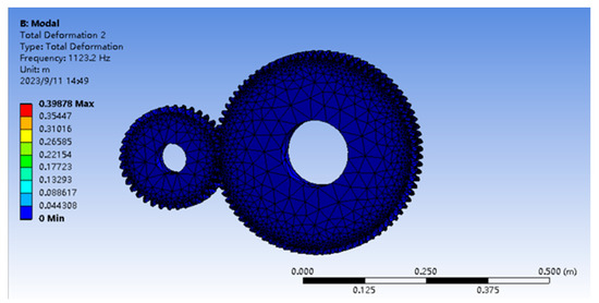
Figure 6.
First-order intrinsic vibration modes of gear pair.
4.2. Harmonic Response Analysis
Gear drives are typically nonlinear systems due to the nonlinear properties introduced by the gears when they mesh, especially gear mesh shocks. It is crucial to consider factors such as the adoption of appropriate initial linearity, which play a key role in the simulation of the dynamic response of the system and can affect the accuracy and confidence of the system simulation results [31]. These nonlinear effects cause harmonic vibrations in the gear system at different frequencies. Harmonic response analysis helps to better understand and predict the impact of these nonlinear effects on acoustic performance. During the operation of a gear system, vibrations and shocks can lead to noise generation. Harmonic response analysis can reveal the vibration and noise generation mechanisms of the different frequency components of a gear system, which can help in taking appropriate control measures to counter these mechanisms. In addition, harmonic response analysis helps to determine whether resonance exists in the gear system. Resonance can lead to a dramatic increase in the amplitude of system vibration and even lead to structural damage or noise problems. By identifying potential resonance frequencies, measures can be taken to avoid resonance problems.
Finally, harmonic response analysis can also be used to optimize the design of gear systems. By analyzing the vibration response at different harmonic frequencies, engineers can adjust the parameters of the gears, such as reducing the nonlinear effects of the gears or optimizing the damping, to improve the acoustic performance of the system. These measures can contribute to the design of quieter and more reliable gear systems. The model and material property settings from the previous modal analysis are copied to define the contact, delimit the mesh of the gear pair, and apply loads and constraints. The modal superposition method is shown in Figure 7:
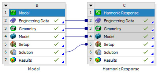
Figure 7.
Modeling the harmonic response analysis.
The modal results are inputted into the harmonic response analysis. Based on the computer’s solving speed and the range of modal frequencies, the swept frequency range of the solution was set to 100–2700 Hz, and the load step was set to 50 Hz. Considering that the gear pair will produce energy consumption due to friction and other factors in the vibration state, the damping of the gear pair system is set to a constant of 0.05 in order to improve the accuracy of the harmonic response analysis results. According to the actual working condition of the gear pair, a torque of 841.5 N·m is applied to the main wheel, and the vibration displacement frequency curve in the X-axis direction is solved by taking the surface connected to the main wheel and the shaft as the study surface, as shown in Figure 8.
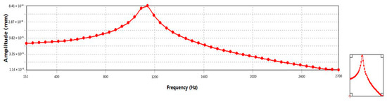
Figure 8.
Displacement frequency curve.
According to the results of the above harmonic response analysis, the amplitude increases first. A peak occurs between 800 Hz and 1200 Hz and begins to decrease slowly after reaching the maximum value. As a rule of thumb, when a gear pair vibrates under the impact of a dynamic load [32], the first mode contributes the most to the overall system, while its intrinsic frequency may be closer to the external excitation frequency. Therefore, when the excitation frequency matches the intrinsic frequency of the first mode, the system is more prone to resonance, which manifests itself as a pronounced peak on the displacement frequency curve. On the contrary, the intrinsic frequencies of the other modes are usually relatively far away from the excitation frequency; so, significant amplitude peaks are less likely to be observed on the displacement frequency curve. This does not mean that the other modes are not involved in the system response but rather that their contribution at a given excitation frequency is relatively small and not sufficient to produce a significant amplitude increase. According to the literature [33], in the vibration harmonic response analysis of the traction gear drive system of CH380A train sets, it was found that the peak frequency of the system vibration displacement was mainly concentrated in the frequency band of 400–1200 Hz, which is consistent with the conclusion of the analysis in Figure 8. Therefore, to improve the stability of the gear system and avoid resonance, external excitation should be avoided as much as possible near these peak frequencies.
4.3. Theory of Radiated Noise and Its Measurement
Noise in gear systems is primarily caused by vibrations. To obtain the radiated noise characteristics of the arc gear system, an acoustic model of the arc gear system is established using acoustic software to predict the radiated noise of the gear. After the model was built, the field point mesh was defined, and finally, the gear noise was solved and analyzed using acoustic analysis software to obtain the acoustic response of the gear subfield point.
In acoustic calculations, the most common calculation method is to solve for the sound field by integrating the Helmholtz formula:
In Formula (4), is Laplace’s algorithm, ; is the sound pressure; is wave number, ; and is the Excitation Circle Frequency ().
The Helmholtz equation describes the spatial distribution of the sound pressure in a stable acoustic field, and given a certain acoustic boundary condition, the radiated sound pressure at that boundary can be determined.
Acoustic quantities such as sound pressure, sound intensity, and sound power can be used to measure the strength of sound. However, owing to the wide range of human hearing and the size of the sound pressure, the sensitivity of the human ear is not a linear relationship between the size of the sound pressure; so, the use of the sound pressure size to calibrate the strength of the sound in an actual project will bring a lot of inconveniences. The same applies to sound intensity and power level. For comparison, a logarithmic scale was used to measure the sound pressure and sound intensity.
Sound pressure level: the ratio of the actual sound pressure value to the reference sound pressure value is taken as a logarithm and then multiplied by 10 with the expression as in Equation [12].
In Formula (5), is the actual sound pressure value and is the reference sound pressure value ().
The sound intensity level can be expressed as in Equation (6):
In Formula (6), is the actual sound intensity value and is the benchmark sound intensity value (), which is the lowest sound intensity perceived by the human ear.
The main research objective of this study is to select the sound pressure level to reflect the noise value of the system by understanding the radiation of noise outward through the air from the gearing system, combined with an analysis of the noise measurement acoustic quantities. For comparison, the RMS value of the sound pressure level of the gearing system over the entire scanning frequency band was chosen as the system noise value. As shown in Figure 9, five suitable field points were selected to verify the sound pressure levels at these points, and the corresponding sound pressure level curves were plotted.
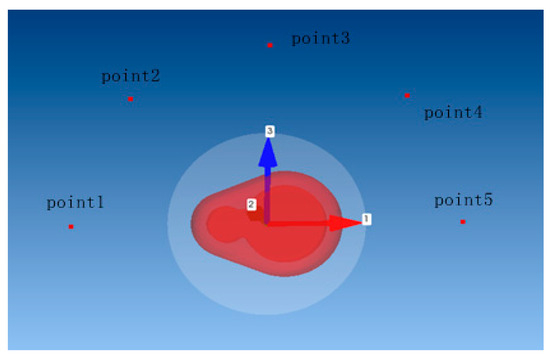
Figure 9.
Distribution locations of the five field points in the free sound field.
4.4. Construction and Analysis of Acoustic Vibration Coupling Models
The vibration response of the gear train obtained via the modal superposition method was imported into the acoustic module of ACTRAN, the acoustic boundary element mesh and parameter settings were created, and finally, the outer envelope was constructed to complete the acoustic–vibrational coupling model. To simulate the position of the passenger in relation to where the gears are located under the compartment and to analyze the magnitude of the noise heard by the passenger, five field points approximately 1 m from the center of the gear subcenter were selected on the created free sound field.
The sound pressure profiles of the radiated noise from the gearing at different field points were obtained by solving Equation (5), as shown in Figure 10. The dB(A) scale was used to more accurately reflect the response of the human ear to frequency. The RMS value of the sound pressure level was selected to derive the dB(A) values for five field points around the gear pair.
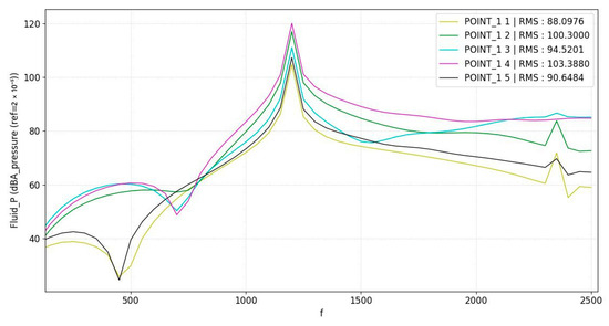
Figure 10.
Sound pressure level curves at each field point.
The five RMS values in Table 6 represent the root mean square (RMS) of the sound pressure level at the corresponding position scanning frequency, that is, the amount of noise perceived by the human ear at the five points. It can be seen that the noise values at all five points are greater than 80 dB(A). Studies have shown that long-term exposure to noise above 80 dB(A) may damage human hearing [4], and radiated noise can be further reduced via subsequent gear trimming.
Table 6.
RMS values for each field site.
5. Comprehensive Gear Shaping
To eliminate the gear teeth meshing in and out of the impact and reduce the shock and vibration of the gear meshing process, the tooth-profile-shaping method is usually used. The three main elements to be determined for tooth profile trimming are the maximum trimming amount , trimming length and trimming curve. Determining reasonable tooth profile modification parameters for the reduction in gear meshing vibration and transmission system noise plays a vital role. Owing to the complexity of the curved surface of arc-toothed cylindrical gears, the trimming design is more difficult. To address this situation, this study designed a comprehensive reshaping scheme based on the tooth profile combined with the radius of the curved-tooth line. According to the existing EMU traction gear modification plan, taking into account modification costs and other factors, only the pinion gear can be modified.
5.1. Maximum Trimming Volume
There are two methods for calculating the maximum trimming amount: the formula method and the finite element method. Because of the relative complexity of the geometry of the arc-toothed cylindrical gears, it is not good to determine the maximum trimming amount using the formula method, whereas the finite element method can effectively deal with this complex structure; therefore, the finite element method is chosen.
The meshing state is illustrated in Figure 11. After static finite element analysis, the displacement value of the pinion tooth top is extracted, which is the maximum trimming amount of the pinion tooth top. The top of the tooth trimmed for the pinion was 30 µm.
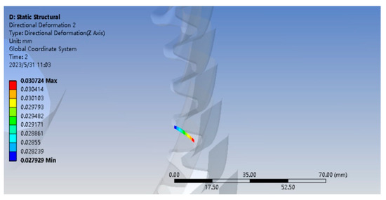
Figure 11.
Extracting the trim amount.
5.2. Modified Length
The trim length in the tooth height direction consisted of a short trim with a small amount of trimming and a long trim with a large amount of trimming. One of the long modifications is mainly from the beginning or end of the engagement to the beginning or end of the single-tooth engagement. The short trim, on the other hand, is trimmed from the beginning or end of the engagement to 1/2 the length of the long trim.
Long trimming under a load corresponds to the amount of trimming, the single pair of teeth meshing area overlap is 1, the transmission error is minimized, and the noise state is optimal. Considering the high degree of axial overlap of the arc-toothed cylindrical gears, a long revision shape was chosen. The trimmed length was calculated using Equation (7) [34].
In Formula (7), is the End Face Overlap Ratio, and is the End Face Datum.
By substituting the pinion design parameters into Equation (7), the trim length was calculated to be 12 mm.
5.3. Shaping Curves
The profile curve is the section of the curve from the position of the maximum profile at the top of the tooth to the end of the profile. There are many commonly used trimming curves, which are generally categorized into linear and curvilinear types. Their equations are expressed as follows [12]:
In the formula, is the relative coordinates of the meshing position measured along the meshing line, with the origin at the alternating point of single- and double-tooth meshing; is the maximum modification amount, is the modification length; and is the power exponent, typically ranging from 1 to 2, with different values corresponding to different modification curves. When = 1, this corresponds to a linear modification, and when = 1.5, this represents the Walker modification curve. is the magnitude of the modification amount at the location.
To establish the trimmed gear model, it is necessary to establish equations for the tooth profile parameters of the trimming curve. The Walker trimming curve can better smooth the contact stress variation than the straight trimming curve [35]. The Walker trimming curve is used.
According to Equation (1), the parametric equation of the modified tooth profile in the right-angle coordinate system is established as follows:
where is the maximum trimming amount, is the trimming length, and when the roll angle is , the radius of the involute at the point is the radius of the tooth apex circle; thus, , where is the radius of the tooth apex circle.
5.4. Radius of an Arcuate Toothed Line
The radius of the arc-toothed line is a unique parameter for involute arc cylindrical gears with an involute tooth profile. For the arc-toothed cylindrical gear, the toothed line radius and its contact strength have a close relationship, and an arc-toothed line radius that is too large or too small is not desirable. In the range of 1.1B ≤ ≤ 1.8B, the arc-toothed cylindrical gear has the longest contact line, the contact stress can be optimized, and the gear has the best load-carrying capacity [36]. As shown in Table 1, the design value of the radius of the arc-toothed line of the arc-toothed cylindrical gear was 80 mm. After many simulation experiments, the radius of the arc-toothed line is increased to 90 mm, as shown in Figure 12, and the maximum contact stress at this moment is the smallest and the strongest load-carrying capacity.
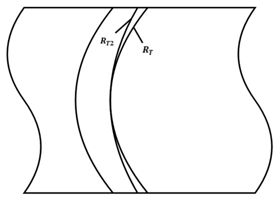
Figure 12.
Curved-tooth line unfolding.
5.5. Constructing Gear Trimming Surfaces
Owing to the limitations of commercial software, existing methods for constructing modified arc gear models are complicated. In this study, we propose a method to reconstruct a virtual reconditioning prototype of gears using MATLAB and CREO, which can quickly and accurately reconstruct the reconditioning gear model. After determining the involute parameter equations, tooth root transition curves, and tooth profile parameter equations for the revision curves, a series of parameters of the gear and the involute revision tooth profile parameter equations are inputted into MATLAB. After numerical computation and visualization of the results, the diametrically repaired profile is obtained, as shown in Figure 13. According to the values of and in the design of the trimming scheme in this section, substituting into Equation (9) can generate involutes under different trimming parameter conditions. The coordinates of the trimmed curves in MATLAB were then imported into CREO, as shown in Figure 14.
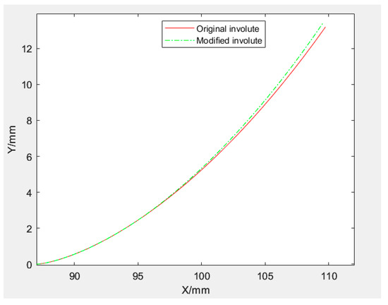
Figure 13.
Trimming curve.
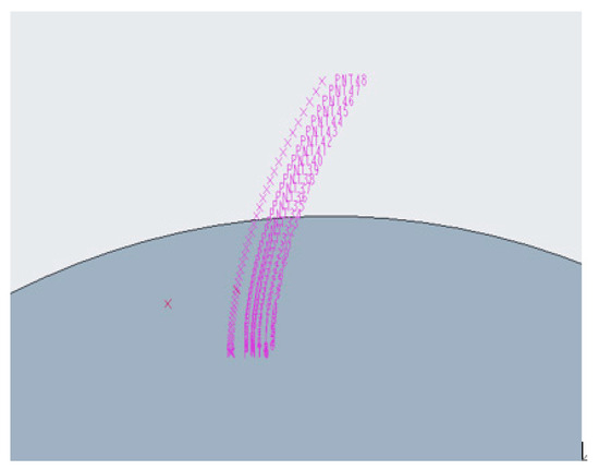
Figure 14.
Coordinate points of trimmed curves.
In CREO, by connecting the coordinate points to involute lines, scanning the entity from the involute lines to form the tooth groove, and generating the solid model after array mirroring based on the original gear, we can complete the parametric modeling of the modified gear. This method can quickly construct a trimmed gear model and significantly improve the design’s efficiency. The scanned formation of the tooth grooves is shown in Figure 15, Figure 16 shows the constructed teeth.
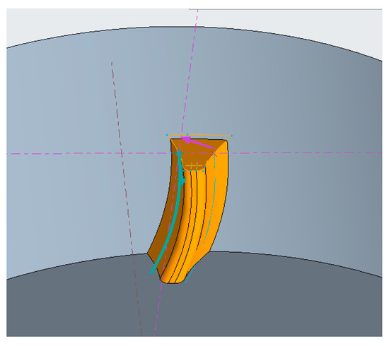
Figure 15.
Scanning of the formed tooth grooves.
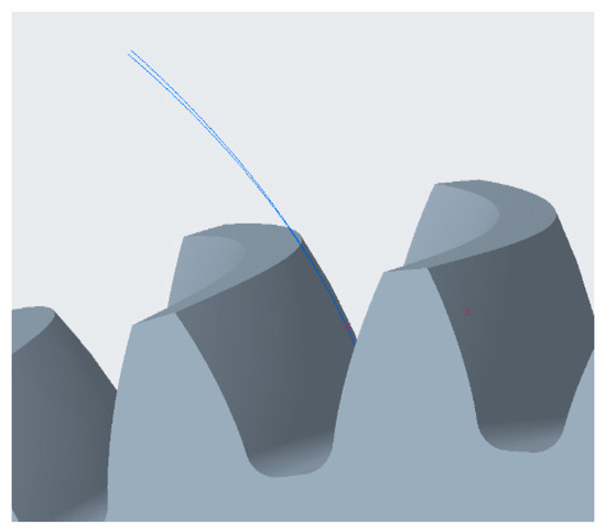
Figure 16.
Constructed gear tooth shape.
5.6. Reconstruction of Gear Model after Trimming
Based on the arc-toothed cylindrical gear trimming parameters designed in this section, the trimmed gear model was reconstructed using the MATLAB and CREO reconstruction of the gear virtual trimming prototype (Figure 17). In this model, the master and follower wheels are assembled using a pin connection. Interference checking with CREO’s own checking function did not show any interference, proving the reliability and accuracy of the adopted trimmed gear modeling approach.
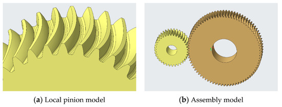
Figure 17.
Models of modified arc-toothed cylindrical gears.
6. Analysis and Comparison of the Effect of the Gears after Reshaping
In this section, the dynamic contact analysis of the gears after reshaping is carried out, and the maximum contact stress in one cycle is derived. It was found that most of the contact stresses in the gears were reduced after trimming. At the same time, ACTRAN acoustic software is utilized to predict the radiated noise, and the simulation results show that the radiated noise values of the gears in the sound field are reduced at all five field points after trimming. These results fully demonstrate the effectiveness of the shaping scheme, further emphasize the significant impact of shaping on gear performance and noise levels, and provide an accurate and reliable assessment for the validation of gear shaping effectiveness.
6.1. Comparison of Contact Stress Analysis after Trimming
As shown in Table 7, after trimming, the contact stress during engagement of the arc-toothed cylindrical gears under sustained working conditions reaches a maximum of 1955.2 MPa, the contact stress during disengagement is 1579.7 MPa, and the stresses during engagement and disengagement are reduced by 23.61% and 29.02%, respectively, which effectively improves the impacts of the gear engagement and disengagement.
Table 7.
Comparison of maximum contact stresses at different moments under continuous operation before and after gear reshaping.
6.2. Comparison of Radiated Noise Analysis after Shaping
Taking the constructed model of the trimmed gear pair and analyzing it according to the simulation flow of radiated noise with modal–harmonic response–acoustic response characteristics in Chapter 4, the obtained sound pressure level curves are shown in Figure 18.
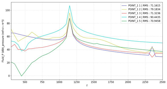
Figure 18.
Sound pressure level curves at each point after trimming.
Comparing with the simulation curve of the unshaped gear pair in Figure 10, the noise reduction effect of shaping is shown in Table 8.
Table 8.
Comparison of radiated noise at each field point before and after the shape modification.
As shown in Table 8, compared with pre-trimming, the noise SPL values of the trimmed gear train at five positions in the sound field were reduced by 19.22% dB(A), 21% dB(A), 24.51% dB(A), 12.53% dB(A), and 21.75% dB(A), respectively, and the radiated noise at four of the points was reduced to less than 80 dB. However, due to the difference between the simulation environment and the actual condition in this paper, the gear vibration noise propagates directly through the air, and the effects of various materials in the propagation path on the sound transmission loss are not considered when setting up the field points [37]. So, the noise felt by passengers in the train car should be lower.
7. Conclusions
In this paper, a curved toothed cylindrical gear adapted to the traction of higher-speed moving train sets is proposed and designed. A parametric model of the arc toothed cylindrical gear transmission system is established by using CREO, the dynamic contact analysis of meshing and acoustic response characteristics are carried out under the continuous working condition of the moving train set, and the maximum contact stress and radiated noise under the continuous working condition are obtained. On this basis, a comprehensive reshaping scheme of the tooth profile combined with the radius of the curved-tooth line is designed, and the virtual reshaping prototype of gears is reconstructed by CREO and MATLAB. The simulation analysis of the modified arc gear cylindrical gears is carried out to compare the dynamic contact characteristics of meshing and radiated noise of the modified arc gear cylindrical gears before and after the modification.
The research process includes the reconstruction of a virtual trimming prototype of a gear. The adopted gear parameters were repeatedly verified and tested to ensure the accuracy of the trimming, including the selection of the size of the radius of the curved-tooth line, which was also subjected to several experiments, and a suitable value was finally determined. In this paper, several analysis methods, including dynamic contact analysis and acoustic response characterization via finite element boundary element method, are used to simulate the dynamic behavior and acoustic response of a real gear system. Finally, the reliability and accuracy of the trimming method were verified via dynamic contact analysis and ACTRAN for noise prediction. These analytical results confirm the reliability and accuracy of this reshaping scheme.
In summary, the research results indicate that the repair program has achieved favorable outcomes, effectively alleviating contact stress and reducing radiation noise, thereby laying a theoretical foundation for the development of the new generation of high-speed EMU traction gear transmission systems. The following conclusions can be drawn from this study:
- (1)
- Parametric modeling of curved-tooth cylindrical gears was performed using CREO software, which can realize the rapid construction of the model, improve the modeling efficiency, save time, and reduce the design cost. By analyzing the dynamics of the constructed gears, the contact path of the arc-toothed cylindrical gears in the meshing process is an elliptical region along the middle of the tooth face, which accounts for approximately 50% of the length of the tooth face, and the contact stresses are more uniformly distributed along the contact line. During the gear meshing process, the maximum contact stress occurs at the meshing-in and meshing-out positions, which are 2559.7 MPa and 2225.2 MPa, respectively, and the contact stress at the meshing-in position reaches the maximum value.
- (2)
- The design of a tooth profile, combined with the radius of the curved tooth line of the comprehensive trimming program, tooth profile trimming selected Walker trimming program, and the program compared to straight-line trimming transition, is smoother and less likely to lead to a stress concentration phenomenon. The load-carrying capacity of an arc toothed cylindrical gear is closely related to its tooth line radius, and the selection of a reasonably sized arc toothed line is directly related to the gear contact stress and noise size. In this study, the radius of the arc toothed line was increased to 90 mm, at which time the contact stress was minimized, and the bearing capacity was the strongest.
- (3)
- A method for reconstructing virtual reconditioning prototypes of gears using MATLAB and CREO allows for a rapid construction of reconditioned gears. The basic parameters of the gears and trimming profile equations are imported into the MATLAB R2022b software, and the construction of trimming curves can be completed quickly by modifying the trimming parameters in the equations. Subsequently, the coordinate points of the trimming curve are imported into the CREO, and the trimming gear model can be constructed using its 3D modeling function. This method only requires stretching and scanning based on the original gear and does not require re-modeling, which greatly improves the design efficiency of the trimmed gear.
- (4)
- Through the dynamic contact analysis and acoustic response characterization of the modified curved tooth cylindrical gear drive system, the contact stresses of the modified gears in the meshing and meshing out are 1955.2 MPa and 1579.7 MPa, respectively. Compared with the pretrimming period, the reductions were of 23.61% and 29.02%, respectively, which effectively reduced the meshing impact and improved the gear transmission’s performance. The five field point values in the sound field were reduced by 19.22% dB(A), 21% dB(A), 24.51% dB(A), 12.53% dB(A), and 21.75% dB(A) for the geared drivetrain after the trim. Therefore, the results of this study show that the comprehensive shape modification scheme can effectively reduce the noise of the traction arc toothed cylindrical gear transmission of high speed EMU and improve passenger comfort.
- (5)
- To highlight the research focus of this study, the traction gear transmission system is simplified, the influence of auxiliary components such as gear shafts and bearings is ignored, and only the design of the gear vice for trimming program and its noise reduction effect analysis is carried out. At the same time, considering the important position of traction gears of moving train sets in the safety of train operation in the future, on the basis of the theoretical research and simulation experiments in this paper, we will continue to conduct research on the trimming processing and loading experiments of traction curved tooth cylindrical gears for the real operating environment of the traction gear transmission system to further validate the theoretical results of this study.
Author Contributions
J.S.: methodology, formal analysis, writing—original draft, writing—review and editing, and data curation; H.L.: data curation, formal analysis, and editing; Z.T.: validation, supervision, funding acquisition, and review; Z.C.: data curation and editing; M.L.: data curation and editing. All authors have read and agreed to the published version of the manuscript.
Funding
This study was supported by the National Natural Science Foundation of China under Grant No. 52262049 and No. 51965017.
Institutional Review Board Statement
Not applicable.
Informed Consent Statement
Informed consent was obtained from all the subjects involved in the study.
Data Availability Statement
The data used in this study are available from the corresponding author upon request. The data are not publicly available due to privacy.
Conflicts of Interest
We declare that we do not have any commercial or associative interests that represent conflicts of interest in connection with the submitted work.
References
- Di, A. Train Headway Simulation of 400 km/h High Speed Railway. Railw. Transp. Econ. 2022, 44, 36–44. [Google Scholar]
- Yang, S.; Wang, X.; Chen, C.; Liu, S. Research Status and Trend of Gearbox Design for High-speed EMU. Mach. Tool Hydraul. 2021, 49, 173–179. [Google Scholar]
- Saito, M.; Mizushima, F.; Wakabayashi, Y.; Kurita, T.; Shinji, N.; Toru, H. Development of New Low-Noise Pantograph for High-Speed Trains. In Proceedings of the 13th International Workshop on Railway Noise, Ghent, Belgium, 16–20 September 2019; Springer International Publishing: Berlin/Heidelberg, Germany, 2021. [Google Scholar]
- Zhang, J.; Xiao, X.; Wang, D.; Zhou, Z.; Jin, S. Characteristics and Evaluation of Noises in the Tourist Cabin of a Train Running at More than 350 km/h. J. China Railw. Soc. 2012, 34, 23–29. [Google Scholar]
- Shen, S.; Liu, X.; Xiang, C. Review of urban noise pollution and monitoring system. Electron. Meas. Technol. 2017, 40, 201–207. [Google Scholar]
- Ma, D.; Wei, Y.; Ye, Z.; Lan, L.; Li, H. Research of Meshing Contact Impact Stress Distribution of Circular Arc Tooth Trace Cylindrical Gear Surface. J. Mech. Transm. 2018, 42, 13–17+22. [Google Scholar]
- Zhang, Q.; Wen, G.; Liang, S.; Tong, Q.; Hou, L.; Yang, G. Prediction mathematic model and influencing factors of contact stress of cylindrical gear with arc tooth. Complexity 2020, 2020, 8888407. [Google Scholar] [CrossRef]
- Tang, Z.; Tang, S.; Sun, J.; Yan, L. Multi-condition contact stress analysis of high speed train helical gear. Period. Polytech. Transp. Eng. 2016, 44, 193–200. [Google Scholar] [CrossRef]
- Zhang, X.; Zhao, S.; Guo, L.; Hou, X.; Li, Z. Research on Low-vibration Tooth Profile Modification Design of Two-stage Planetary Gear Transmission System. Mech. Eng. 2023, 1, 60–65. [Google Scholar]
- Gao, P.; Liu, H.; Yan, P.; Xie, Y.; Xiang, C.; Wang, C. Research on application of dynamic optimization modification for an involute spur gear in a fixed-shaft gear transmission system. Mech. Syst. Signal Process. 2022, 181, 109530. [Google Scholar] [CrossRef]
- Hao, L.; Li, W.; Zhang, X. Impact of Gear Modification on Gear Dynamic Characteristics. J. Fail. Anal. Prev. 2023, 23, 853–864. [Google Scholar] [CrossRef]
- Tang, Z.; Wang, M.; Hu, Y.; Mei, Z.; Sun, J.; Yan, L. Optimal design of traction gear modification of high-speed EMU based on radial basis function neural network. IEEE Access 2020, 8, 134619–134629. [Google Scholar] [CrossRef]
- Deng, J.; Nie, S.; Deng, X.; Jiang, C. Tooth surface mismatch modification method of cycloidal bevel gear based on conjugate tooth surface modification. J. Adv. Mech. Des. Syst. Manuf. 2020, 14, JAMDSM0017. [Google Scholar] [CrossRef]
- Feng, Z.; Xiong, G.; Gao, L.; Luo, C. Study on Modification and Tooth Tip Sharping Analysis of Orthogonal Arc Tooth Face Gears. J. Mech. Transm. 2022, 46, 38–44. [Google Scholar]
- Yan, G.; Yu, D.; Zhong, F. Dynamic Contact Stress Analysis of Spur Gear Modification Based on Modification Condition. Mach. Des. Manuf. 2022, 8, 193–196. [Google Scholar]
- Zhang, Y.; Liu, K.; Xie, G.; Zhang, Z. Optimization Design of Inclined Gear Surface Based on ROMAX. Mach. Tool Hydraul. 2023, 51, 89–94. [Google Scholar]
- Wang, C. Multi-objective optimal design of modification for helical gear. Mech. Syst. Signal Process. 2021, 157, 107762. [Google Scholar] [CrossRef]
- Bing, Y.; Shan, C.; Geng, L.; Lan, L.; Lehao, C. Sensitivity Analysis of Helical Gears with Tooth Surface Modification to Applied Torque and Gear Misalignment. J. Northwestern Polytech. Univ. 2018, 36, 1085–1092. [Google Scholar]
- Feng, Q.; Wang, T.; Wang, L.; Xia, H.; Dong, Y.; Wang, Y. Modification of Differential Gear based on Multi-objective Optimization. J. Mech. Transm. 2020, 44, 153–158. [Google Scholar]
- Wang, C.; Shi, M. Optimal Modification of Helical Gear Tooth Surface based on KISSsoft. J. Mech. Transm. 2018, 42, 85–90. [Google Scholar]
- Hajjaj, A.; Corrigan, K.; Mohammadpour, M.; Theodossiades, S. On the stability analysis of gear pairs with tooth profile modification. Mech. Mach. Theory 2022, 174, 104888. [Google Scholar] [CrossRef]
- Xing, H.; Yang, C.; Yu, N.; Xu, C.; Jiang, J. Micro-parameter Optimization of Helical Cylindrical Gear based on Romax. J. Mech. Transm. 2021, 45, 85–89+138. [Google Scholar]
- Mu, Y.; He, X.; Fang, Z. An innovative ease-off flank modification method based on the dynamic performance for high-speed spiral bevel gear with high-contact-ratio. Mech. Mach. Theory 2021, 162, 104345. [Google Scholar] [CrossRef]
- Wei, B.; Cao, X.; Deng, X. Simulation and Analysis on Tooth Meshing Ease-Off Surface of Gears Based on Polynomial Topology Modification. J. Northwestern Polytech. Univ. 2020, 38, 897–903. [Google Scholar] [CrossRef]
- Shih, Y.-P. A novel ease-off flank modification methodology for spiral bevel and hypoid gears. Mech. Mach. Theory 2010, 45, 1108–1124. [Google Scholar] [CrossRef]
- Wang, Q.; Zhou, C.; Gui, L.; Fan, Z. An ease-off based approach to designing a high-order transmission motion for face-milled spiral bevel gears. Int. J. Veh. Des. 2019, 81, 241–264. [Google Scholar] [CrossRef]
- Zhang, X.; Liang, Z. Review on Research Status of Curvilinear Cylindrical Gear. J. Mech. Transm. 2020, 44, 140–150. [Google Scholar]
- Tang, Z.; Sun, J. The Accurate Parametric Design and Assembly Simulation of the Spread Blade Cylindrical Gears with Curvilinear Tooth Trace. Mach. Tool Hydraul. 2010, 38, 108–111. [Google Scholar]
- Zhang, C.; Li, D.; Guo, S.; Shang, Z. Transient dynamics analysis of non-circular planetary gear train. Heavy Mach. 2016, 05, 76–80. [Google Scholar]
- Tan, J.; Li, X.; Luo, G.; Peng, T.; Yang, Y.; Ning, L. Mesh Control Strategy for Contact Simuliation of Helical Gear Pair of Offshore Wind Power Gearbox. Ship Eng. 2022, 44, 122–126. [Google Scholar]
- Doorly, M.C.; Gilchrist, M.D. Three-dimensional multibody dynamics analysis of accidental falls resulting in traumatic brain injury. Int. J. Crashworthiness 2009, 14, 503–509. [Google Scholar] [CrossRef]
- Yang, S.; Yu, W.; Wang, D.; Wang, F.; Liu, S. Research on Constraint Modal Model of Double Circular-Arc Gear Based on Orthogonal Experiment. Mach. Tool Hydraul. 2022, 50, 40–44. [Google Scholar]
- Tang, Z.; Chen, Z.; Sun, J.; Lu, M.; Liu, H. Noise Prediction Study of Traction Arc Tooth Cylindrical Gears for New Generation High-Speed Electric Multiple Units. Lubricants 2023, 11, 357. [Google Scholar] [CrossRef]
- Shang, Z.; Wang, H. Finite Element Analysis on Profile Modification in Speed Increase Gearbox for the Wind-driven Generator. J. Mech. Transm. 2009, 33, 69–71+137. [Google Scholar]
- Wang, Z.; Zheng, P.; Zhao, W. Influence of Walker Curve Tooth Root Modification on Thermoelastic Grease Lubrication Characteristics of Large Internal Gears. J. Mech. Transm. 2023, 47, 8–16+22. [Google Scholar]
- You, Y.; Hou, L.; Yan, L.; Sun, Z. Modeling and Contact Analysis of Circular-arc-tooth-trace Cylindrical Gear for Manufacture. J. Mech. Transm. 2015, 39, 62–65. [Google Scholar]
- Talebitooti, R.; Zarastvand, M. The effect of nature of porous material on diffuse field acoustic transmission of the sandwich aerospace composite doubly curved shell. Aerosp. Sci. Technol. 2018, 78, 157–170. [Google Scholar] [CrossRef]
Disclaimer/Publisher’s Note: The statements, opinions and data contained in all publications are solely those of the individual author(s) and contributor(s) and not of MDPI and/or the editor(s). MDPI and/or the editor(s) disclaim responsibility for any injury to people or property resulting from any ideas, methods, instructions or products referred to in the content. |
© 2023 by the authors. Licensee MDPI, Basel, Switzerland. This article is an open access article distributed under the terms and conditions of the Creative Commons Attribution (CC BY) license (https://creativecommons.org/licenses/by/4.0/).