
Integrated Design of Hydraulic Coupling Bolts for Large Shaft Systems


Abstract
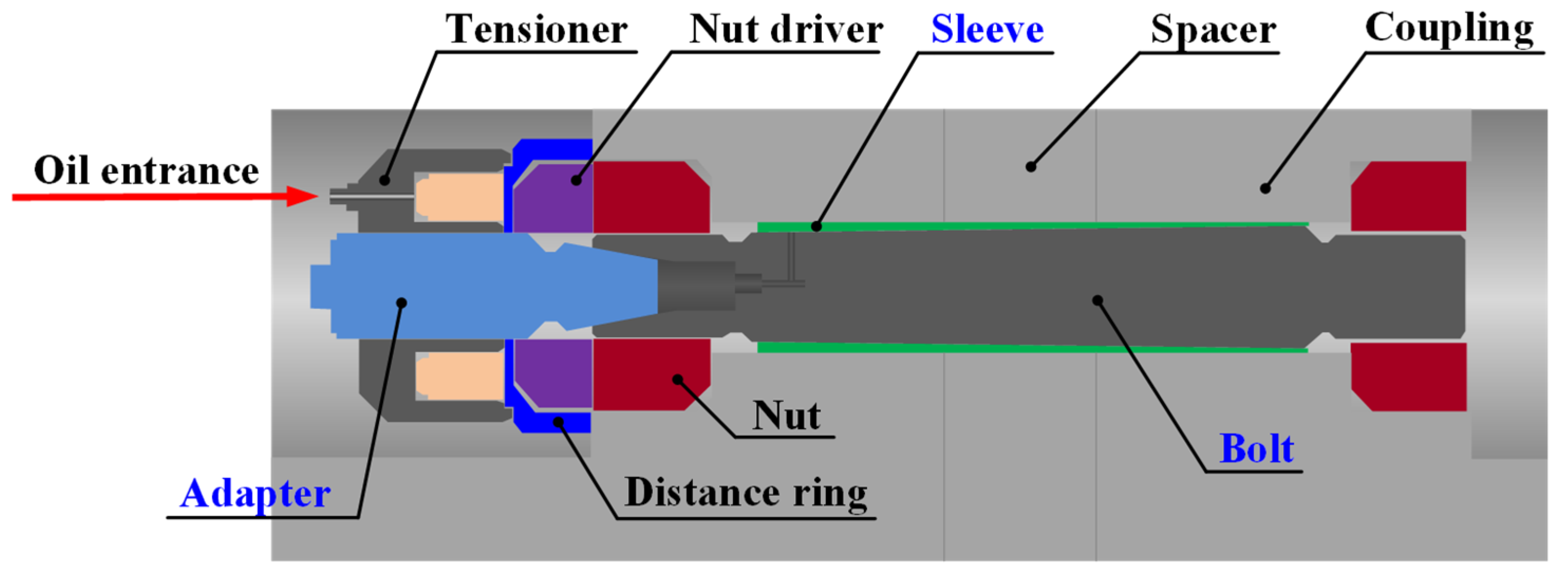
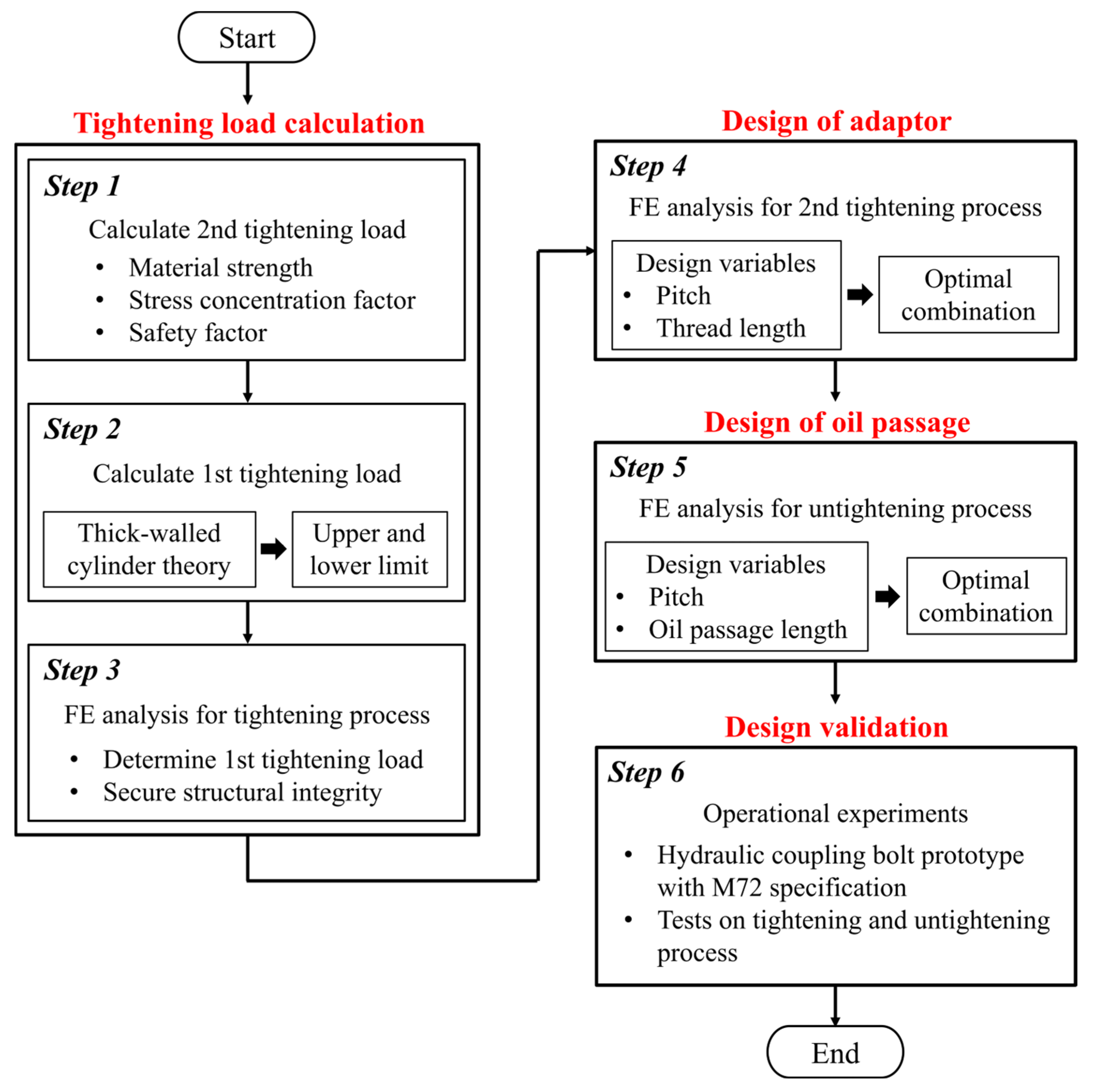
:1. Introduction
2. Calculation of Tightening Load
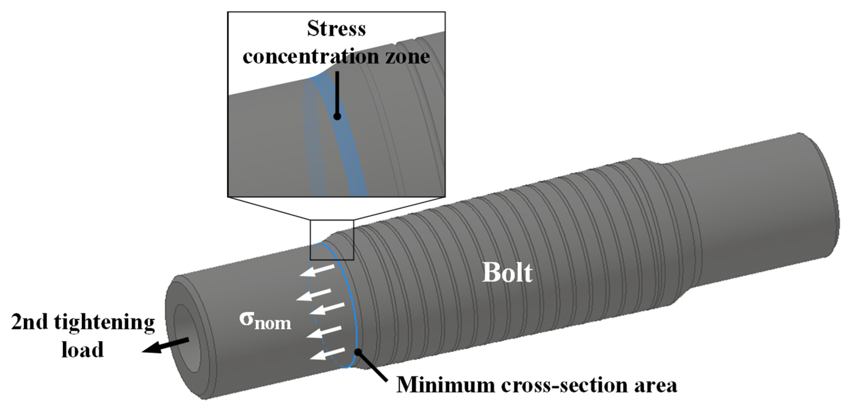
2.1. Second Tightening Load
2.2. First Tightening Load
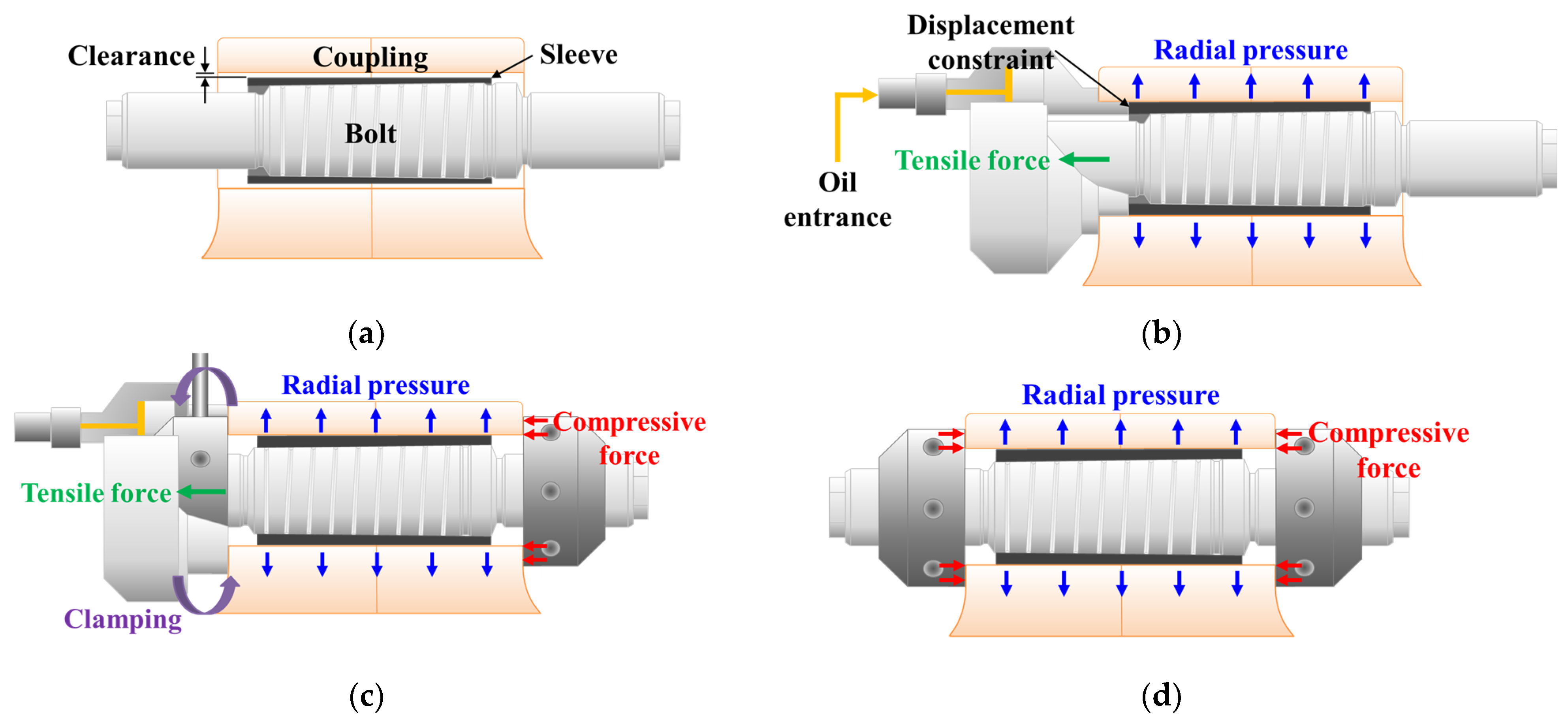
2.3. FE Analysis for Tightening Process
3. Design of Adapter Shape
3.1. Design Variables
3.2. FE Analysis of Structural Integrity of Adapter
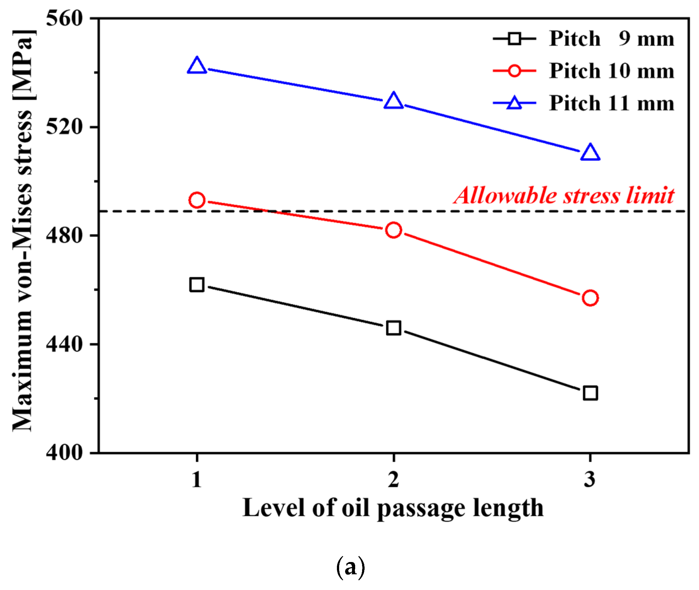
4. Design of Oil Passage Shape
4.1. Design Variables
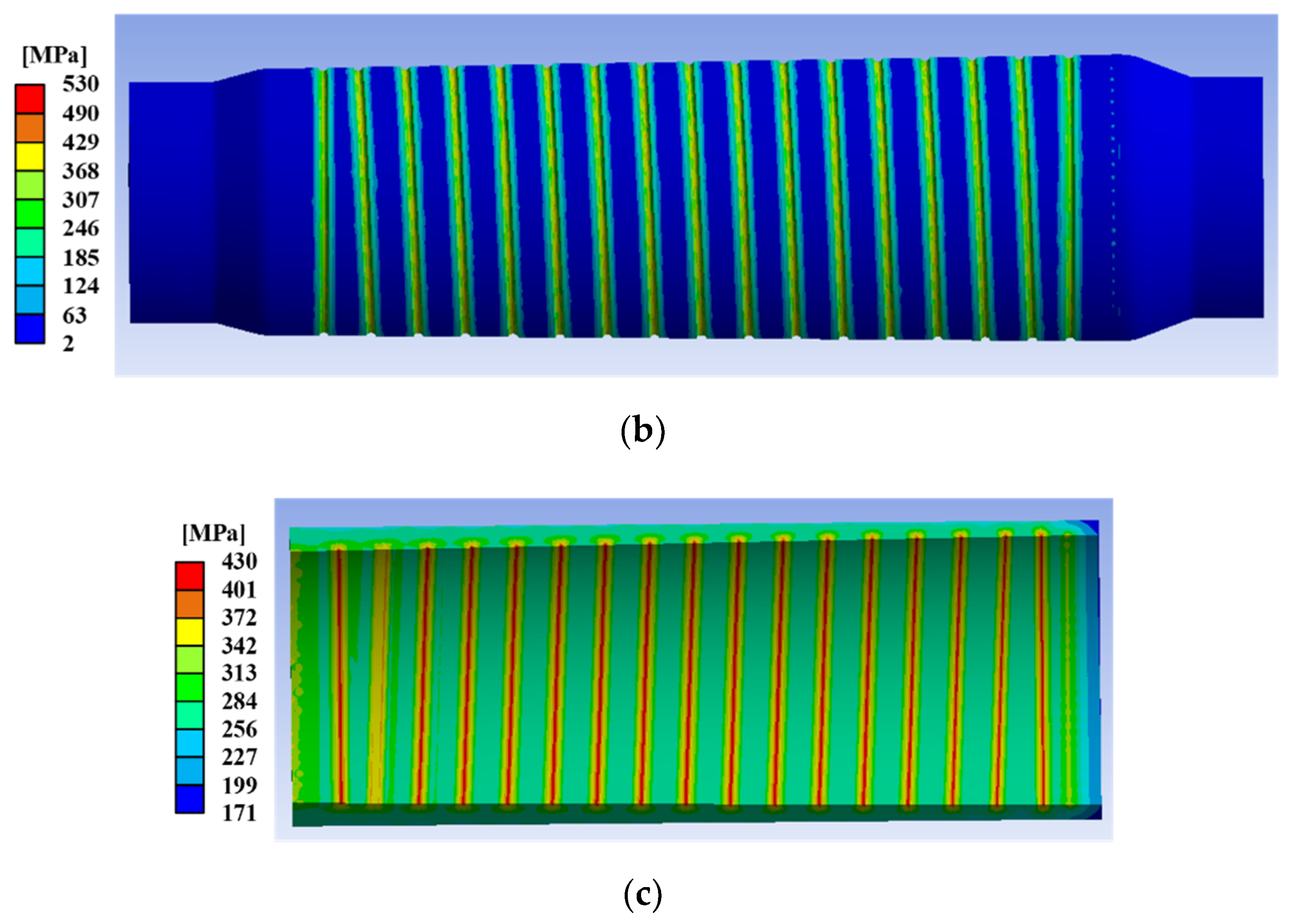
4.2. FE Analysis of Untightening Process
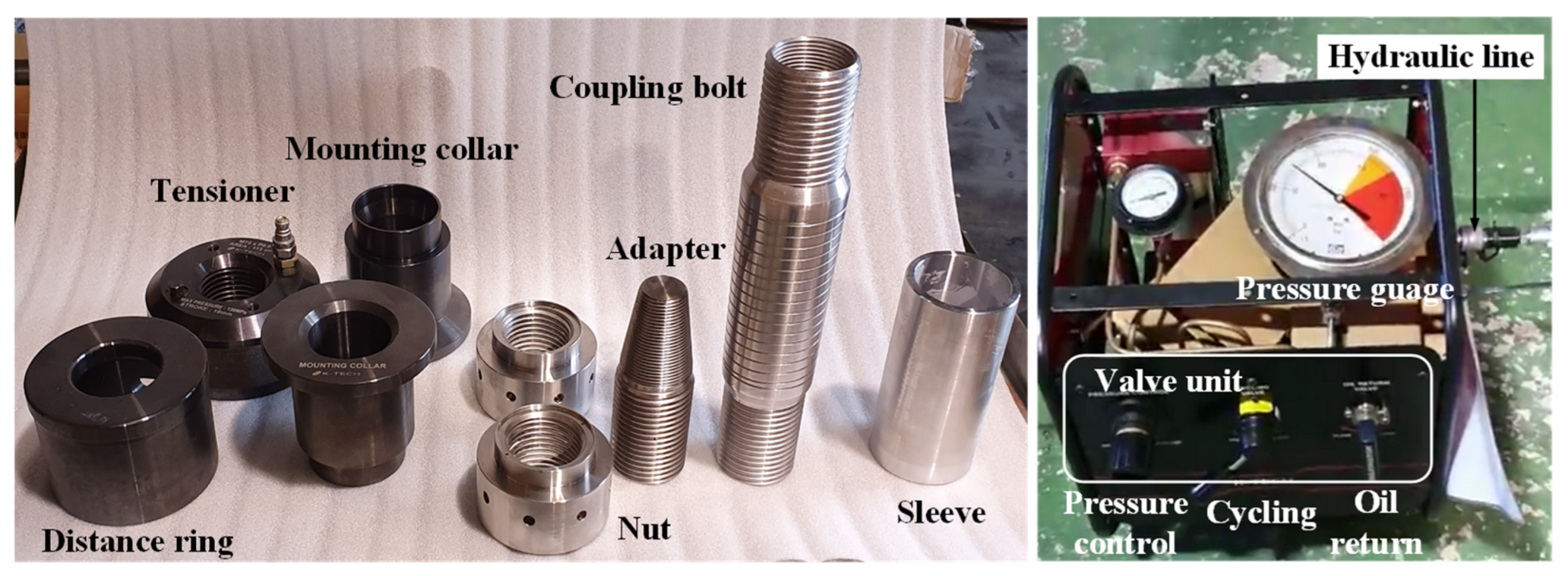
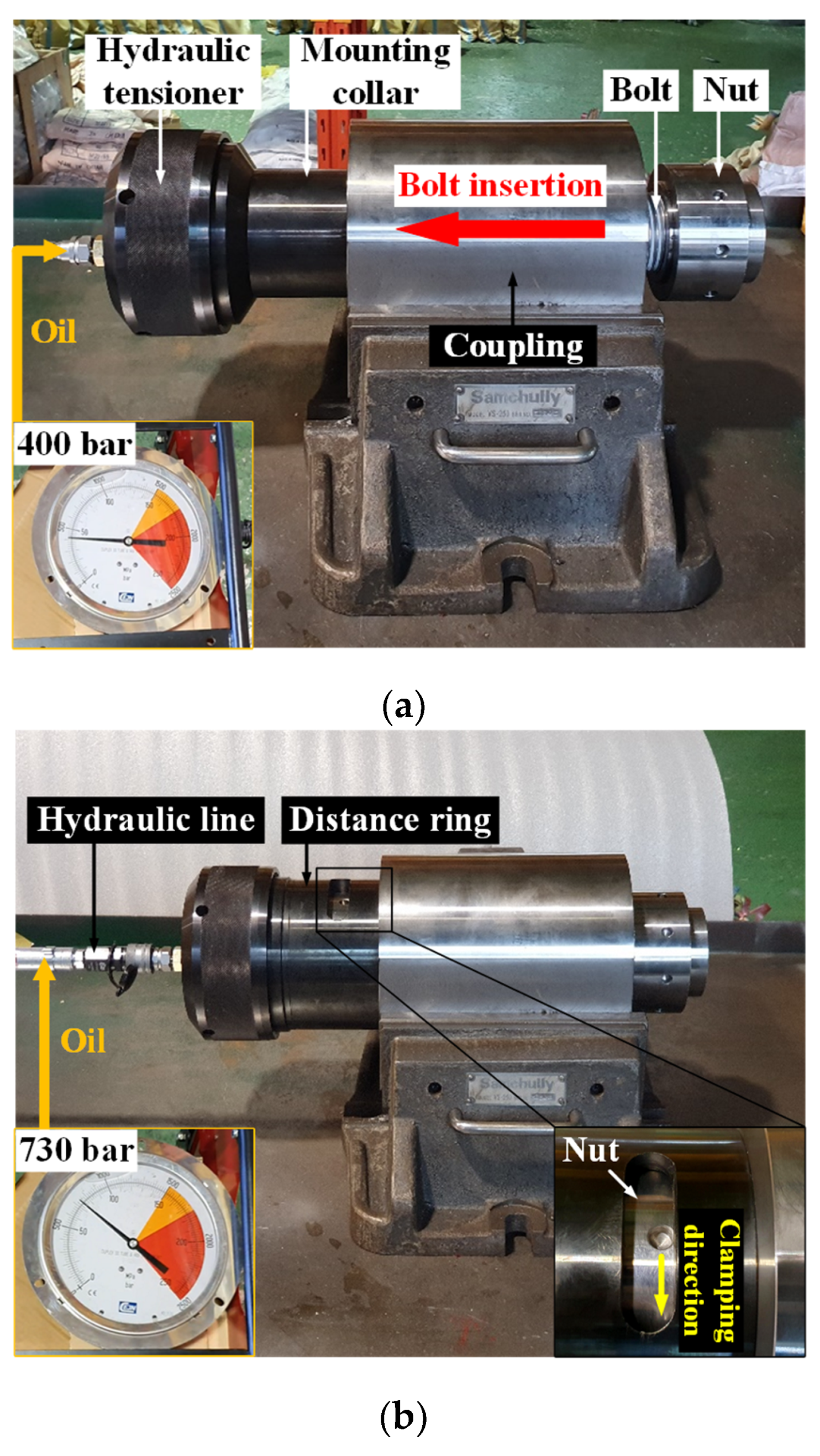
5. Operational Experiment of Hydraulic Coupling Bolts
6. Conclusions
Author Contributions
Funding
Institutional Review Board Statement
Informed Consent Statement
Data Availability Statement
Conflicts of Interest
References
- Wittenburg, J. Shaft Couplings. In Kinematics; Springer: Berlin/Heidelberg, Germany, 2016; pp. 387–410. [Google Scholar]
- Ji, Y.; Lu, Q. A Novel Differential Evolution Algorithm for a Flange Coupling Using ANSYS Simulations. Front. Mater. 2022, 9, 109459. [Google Scholar] [CrossRef]
- Da Silva Tuckmantel, F.W.; Cavalca, K.L. Vibration Signatures of a Rotor-Coupling-Bearing System under Angular Misalignment. Mech. Mach. Theory 2019, 133, 559–583. [Google Scholar] [CrossRef]
- Tadeo, A.T.; Cavalca, K.L. A Comparison of Flexible Coupling Models for Updating in Rotating Machinery Response. J. Braz. Soc. Mech. Sci. Eng. 2003, 25, 235–246. [Google Scholar] [CrossRef]
- Ghiţescu, M.; Ghiţescu, I.M.; Borza, P.N.; Vlase, S. A New Optimized Solution for a Flexible Coupling with Bolts Used in the Mechanical Transmissions. Symmetry 2021, 13, 171. [Google Scholar] [CrossRef]
- Ghitescu, M.; Ghitescu, I.M.; Vlase, S.; Borza, P.N. Experimental Dynamic Rigidity of an Elastic Coupling with Bolts. Symmetry 2021, 13, 989. [Google Scholar] [CrossRef]
- Zhao, S.; Zhang, X.; Zhang, S.; Safaei, B.; Qin, Z.; Chu, F. A Unified Modeling Approach for Rotating Flexible Shaft-Disk Systems with General Boundary and Coupling Conditions. Int. J. Mech. Sci. 2022, 218, 107073. [Google Scholar] [CrossRef]
- Avendano, R.D.; Childs, D.W. One Explanation for Two-Times Running Speed Response Due to Misalignment in Rotors Connected by Flexible Couplings. J. Eng. Gas Turbines Power 2013, 135, 062501. [Google Scholar] [CrossRef]
- Francis, A.; Avdeev, I.; Hamann, J.; Ananthasivan, S. Accurate Characterization of Torsional Stiffness of Flexible Disk Couplings. J. Eng. Gas Turbines Power 2015, 137, 082504. [Google Scholar] [CrossRef]
- Verucchi, C.; Bossio, J.; Bossio, G.; Acosta, G. Misalignment Detection in Induction Motors with Flexible Coupling by Means of Estimated Torque Analysis and MCSA. Mech. Syst. Signal Process. 2016, 80, 570–581. [Google Scholar] [CrossRef]
- Xu, M.; Marangoni, R.D. Vibration Analysis of a Motor-Flexible Coupling-Rotor System Subject to Misalignment and Unbalance, Part I: Theoretical Model and Analysis. J. Sound Vib. 1994, 176, 663–679. [Google Scholar] [CrossRef]
- Ri, K.; Choe, K.; Han, P.; Wang, Q. The Effects of Coupling Mechanisms on the Dynamic Analysis of Composite Shaft. Compos. Struct. 2019, 224, 111040. [Google Scholar] [CrossRef]
- Jeong, H.S.; Son, C.W.; Cho, J.R.; Kim, T.H. Study on Design of Coupling Bolt for Shaft in Power Plant. Trans. Korean Soc. Mech. Eng. A 2013, 37, 707–713. [Google Scholar] [CrossRef]
- Shepstone, S. Design of Shaft Coupling Bolts. In Proceedings of the Propellers/Shafting ’94 Symposium, Virginia Beach, VA, USA, 20–21 September 1994. [Google Scholar]
- Lee, J.O.; Kim, B.J.; Park, J.S.; Jung, S.S. A Study on the Con-Rod Bolt Tightening for a Medium Speed Engine. In Proceedings of the KSME 2006 Spring Conference, Jeju, Republic of Korea, 7–9 June 2006. [Google Scholar]
- Cho, S.S.; Chang, H.; Lee, K.W. Finite Element-Based Fatigue Assessment of Engine Connecting-Rod Bolts. Trans. Korean Soc. Automot. Eng. 2008, 16, 14–20. [Google Scholar]
- Ryu, C.U.; Choi, J.H.; Park, J.H.; Kim, J.H. Study of Structural Integrity for Marine Sleeve Type Hydraulic Bolt. In Proceedings of the KFMA Annual Meeting, Jeju, Republic of Korea, 4–5 December 2008; pp. 639–640. [Google Scholar]
- Jang, S.J. A Study on the Development of Coupling Bolt and Sleeve Used in the Turbines for Nuclear Power. Master’s Thesis, Busan University, Busan, Republic of Korea, 2011. [Google Scholar]
- Nils, J.; Dilip, K.; Herbert, R. Coupling Bolt Failures In Short Shaft Systems For Two-Stroke Engine Installations. In Proceedings of the SNAME Maritime Convention, Washington, DC, USA, 1–5 November 2016. [Google Scholar]
- Wu, Y.T.; Qin, Z.; Eizad, A.; Lyu, S.K. Design and Numerical Simulation-Based Optimization of a Novel Flat-Face Coupling System for Hydraulic Power Equipment. Appl. Sci. 2021, 11, 388. [Google Scholar] [CrossRef]
- Ugural, A.C. Mechanical Design of Machine Components, 2nd ed.; CRC Press: Boca Raton, FL, USA, 2016. [Google Scholar]
- Moaveni, S. Finite Element Analysis Theory and Application with ANSYS, 3rd ed.; Pearson Education: Delhi, India, 2011. [Google Scholar]
- Zehner, B.; Börner, J.H.; Görz, I.; Spitzer, K. Workflows for Generating Tetrahedral Meshes for Finite Element Simulations on Complex Geological Structures. Comput. Geosci. 2015, 79, 105–117. [Google Scholar] [CrossRef]
- O’Malley, B.; Kópházi, J.; Eaton, M.D.; Badalassi, V.; Warner, P.; Copestake, A. Pyramid Finite Elements for Discontinuous and Continuous Discretizations of the Neutron Diffusion Equation with Applications to Reactor Physics. Prog. Nucl. Energy 2018, 105, 175–184. [Google Scholar] [CrossRef]
- Schneider, T.; Hu, Y.; Gao, X.; Dumas, J.; Zorin, D.; Panozzo, D. A Large-Scale Comparison of Tetrahedral and Hexahedral Elements for Solving Elliptic PDEs with the Finite Element Method. ACM Trans. Graph. 2022, 41, 1–14. [Google Scholar] [CrossRef]
- Xu, H.; Shi, T.; Zhang, Z.; Shi, B. Loading and Contact Stress Analysis on the Thread Teeth in Tubing and Casing Premium Threaded Connection. Math. Probl. Eng. 2014, 2014, 28707. [Google Scholar] [CrossRef]
- Majzoobi, G.H.; Dabbagh, M.A.-M.; Asgari, P.; Pipelzadeh, M.K.; Hardy, S.J. Improvement of performance of bolt-nut connections, Part I: Simulations. Proc. Inst. Mech. Eng. Part C J. Mech. Eng. Sci. 2014, 228, 3069–3077. [Google Scholar] [CrossRef]
- Fukuoka, T.; Nomura, M. Proposition of Helical Thread Modeling with Accurate Geometry and Finite Element Analysis. J. Press. Vessel Technol. 2008, 130, 011204. [Google Scholar] [CrossRef]


| Material | Yield Stress [MPa] | Tensile Strength [MPa] | Elongation [%] |
|---|---|---|---|
| SNCM439 | 700 | 1100 | 12 |
| Parameters | Values |
|---|---|
| F2,max [kN] | 2492 |
| Amin [mm2] | 4059 |
| F2,ar [kN] | 1000 |
| σnom [MPa] | 246 |
| σmax [MPa] | 424 |
| Kt | 1.72 |
| SF | 2.0 |
| F2 [kN] | 825 |
| At [mm2] | 11,310 |
| P2 [bar] | 730 |
| Variables | Level 1 | Level 2 | Level 3 |
|---|---|---|---|
| Pitch [mm] | 2 | 3 | - |
| Thread length [mm] | 61 | 76 | 91 |
| Simulation No. | Pitch [mm] | Thread Length [mm] |
|---|---|---|
| 1 | 2 | 61 |
| 2 | 2 | 76 |
| 3 | 2 | 91 |
| 4 | 3 | 61 |
| 5 | 3 | 76 |
| 6 | 3 | 91 |
| Variables | Level 1 | Level 2 | Level 3 |
|---|---|---|---|
| Pitch [mm] | 9 | 10 | 11 |
| Oil passage length [mm] | 154 | 158 | 162 |
| Simulation No. | Pitch [mm] | Oil Passage Length [mm] |
|---|---|---|
| 1 | 9 | 154 |
| 2 | 9 | 158 |
| 3 | 9 | 162 |
| 4 | 10 | 154 |
| 5 | 10 | 158 |
| 6 | 10 | 162 |
| 7 | 11 | 154 |
| 8 | 11 | 158 |
| 9 | 11 | 162 |
Disclaimer/Publisher’s Note: The statements, opinions and data contained in all publications are solely those of the individual author(s) and contributor(s) and not of MDPI and/or the editor(s). MDPI and/or the editor(s) disclaim responsibility for any injury to people or property resulting from any ideas, methods, instructions or products referred to in the content. |
© 2023 by the authors. Licensee MDPI, Basel, Switzerland. This article is an open access article distributed under the terms and conditions of the Creative Commons Attribution (CC BY) license (https://creativecommons.org/licenses/by/4.0/).
Share and Cite
Park, S.-C.; Lee, I.-K.; Lee, S.-K.; Lee, K.-H. Integrated Design of Hydraulic Coupling Bolts for Large Shaft Systems. Appl. Sci. 2024, 14, 130. https://doi.org/10.3390/app14010130
Park S-C, Lee I-K, Lee S-K, Lee K-H. Integrated Design of Hydraulic Coupling Bolts for Large Shaft Systems. Applied Sciences. 2024; 14(1):130. https://doi.org/10.3390/app14010130
Chicago/Turabian StylePark, Sung-Cheol, In-Kyu Lee, Sang-Kon Lee, and Kyung-Hun Lee. 2024. "Integrated Design of Hydraulic Coupling Bolts for Large Shaft Systems" Applied Sciences 14, no. 1: 130. https://doi.org/10.3390/app14010130
APA StylePark, S.-C., Lee, I.-K., Lee, S.-K., & Lee, K.-H. (2024). Integrated Design of Hydraulic Coupling Bolts for Large Shaft Systems. Applied Sciences, 14(1), 130. https://doi.org/10.3390/app14010130