Abstract
For rectangular section tunnel construction, soil bin pressure fluctuates under biaxial emergence conditions. Support pressure is difficult to uniformly distribute, and it can easily cause instability of the tunneling face. The Silo-wedge model is used to perform horizontal strip splitting of parts of the soil at risk for instability under unsupported conditions. In the ultimate equilibrium analysis, the strength discounting method is introduced, a new expression for the safety factor is derived by combining the horizontal strip splitting equilibrium equations, and the safety factor is solved numerically. When the opening range is greater than 0.75 and the effective internal friction angle of the soil is less than 25°, the safety coefficient is less than 1, and destabilization damage is likely to occur. The field application of a box tunnel project in Suzhou demonstrates that the research results have good engineering applicability to the issue.
1. Introduction
Rectangular tunnels are frequently used in the construction of urban underground space initiatives such as metros, due to their benefits, such as better space utilization and less interference with surface traffic. Most urban construction employs non-excavation methods, with rectangular boring machines used for excavation. Large rectangular tunnel sections with an uneven pressure distributions and large pressure differences can easily lead to ground instability. In exceptional situations, such as when clearing openings, the local support pressure may be zero, significantly raising the risk of ground instability.
Regarding the stability of tunnel working faces, many studies have employed limit equilibrium, limit analysis [1,2,3,4,5,6,7,8,9], numerical analysis [10,11,12,13], laboratory experiments [14,15,16,17,18], and other methods. The limit equilibrium method has been extensively applied due to its straightforward concept and physical meaning. Most analyses of limit equilibrium have been based on the silo-wedge model and determined by force equilibrium. Horn [19] first proposed the wedge calculation model based on Janssen’s [20] silo theory, and this model has been continuously enhanced by subsequent research. Overlying soil is an important part of the research of the silo-wedge model. Jancsecz et al. [21] considered the arching effect of overlying soil. Nv et al. [22] utilized the silo-wedge model to investigate the impact of overlying soil on passive and active surface failure and to determine the critical covering depth for shield tunnels. Chen et al. [23] established the concept of the multi-arch; identified the bearing arch at the upper end of the arch area, the friction area in the middle, and the stability area; and consequently proposed a three-dimensional multi-arch model. In addition, Anagnostou et al. [24,25] used a theoretical model to examine the stability of the excavation surface of mud water-type and earth pressure-balanced-type shield machines, considering the effect of mud-water injection on the excavation surface and groundwater seepage force. Broere et al. [26] adapted the computational model to unevenly stratified soil conditions to determine the ultimate supporting pressure of soil pressure and mud-water balanced shield construction. Wei [27,28] modified the model into a trapezoidal wedge shape and optimized the ultimate supporting force calculation results. Lei et al. [29] analyzed the stability of a shield tunnel excavation face under inclined conditions and calculated the ultimate supporting force. Xu et al. [30] adapted the trapezoidal wedge model to rectangular pipe jacking to investigate the stability of a rectangular pipe jacking excavation face in a sand gravel stratum. Cheng et al. [31] assumed that the sliding block in the failure zone had the shape of a curved wedge and determined the active limit supporting force of the excavation face under dry sand conditions. Zhang et al. [32] analyzed the critical failure mode of a tunnel face under various parameters in the limit equilibrium state and calculated the safety factor using the horizontal strip method [33] and the strength reduction method. Paternesi [34] investigated the stability of a tunnel face using the numerical method, and the automatic calculation of the safety factor was performed with Plaxis 3D, using the strength reduction technique. Existing theories concentrate mainly on the uniform support force, while studies of local support have been limited. However, there will be situations of no local support in practical engineering, such as opening the warehouse to clear obstacles.
This paper investigates the stability of a rectangular tunnel face. In consideration of the uneven pressure distribution of the face support, i.e., the characteristics of local support, the concept of strength reduction is introduced into the limit equilibrium analysis, and force analysis is conducted using the silo-wedge model and horizontal bar division method. By solving the derived differential equation, the stability safety factor is obtained. By employing parameter analysis, the influence of various factors on stability was investigated. The theoretical method was then applied to the Suzhou project for verification, and the model’s reliability was evaluated.
2. Materials and Methods
2.1. Pressure Distribution Characteristics in Rectangular Tunnels
A rectangular tunnel was bored through the ground, as shown in Figure 1a. The working face of the rectangular tunnel had a height of D, a width of L, and a burial depth of C. The overload on the ground is expressed as and is assumed to be = 0 kPa considering that, in practice, road traffic above the working face will be prohibited when clearing. The rectangular tunnel section was large, the boring machine used multiple cutters, the opening rate was high, and the pressure in the earth bin was prone to wave movement and uneven distribution. Based on the characteristics of the cutter disc and screw outlet, the cut soil was discharged through the bottom outlet. Figure 1b shows that, as the soil was discharged from the area near the outlet of the double screw excavator, assuming that the soil in the silo had been modified to have better fluidity, the upper part and the surrounding soil then collapsed so that the central region was more affected, and the remaining two parts were much less affected, the residual soil served as a support for the working surface, and the pressure was stabilized at s1; the air pressure in the central region was low and unstable. The pressure fluctuation zone was formed, and the pressure s2 was smaller than s1. Therefore, the working face was supported non-uniformly, and the support pressure had a distribution that was large on both sides and small in the middle. Based on this distribution, the working face was divided into three sections, and to simplify the calculation, the central irregular empty area was simplified into a rectangle, as depicted in Figure 1c. The width of the central fluctuation zone was B, while the support pressure in the stable zone was s1. This paper assumes that the geology was homogeneous and obeyed the linear Moore-Coulomb criterion. The effective internal friction of the soil body was The effective cohesion was and the soil weight was .
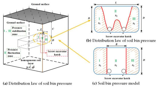
Figure 1.
Characteristics of pressure distribution in soil bin of rectangular roadheader. Ι and ΙΙΙ are pressure stabilisation zones. ΙΙ is a pressure fluctuation zone.
Tunneling for the T221 project in Singapore [35] was suspended multiple times due to encountered obstacles, resulting in a reduction in support pressure. As illustrated in Figure 2, rectangular pipe jacking machines were equipped with man bins to open the bins under pressure to remove obstacles, such as steel fragments, from the soil bins. As a result, the pressure increased, and settlement was better controlled during the opening process. However, due to cost constraints, the majority of rectangular boring machines were not equipped with man bins; consequently, bin opening was usually performed under atmospheric pressure, which is dangerous. In the case of an underground project connected to a station on Suzhou Line 5, the pipe jacking machine was dug into the soft soil and encountered block-filling during construction, resulting in poor soil discharge. The jacking machine was not equipped with a human silo, so the spiral earth-exit was eliminated, and the obstacle was removed through the bottom silo door. This process led to a stability study for the most unfavorable case of opening the bunker (s2 = 0, s1 ≠ 0).
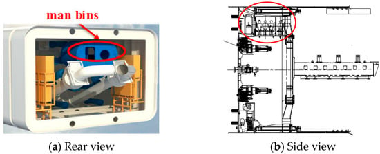
Figure 2.
Location schematic diagram of man lock.
2.2. Theoretical Model Construction
As shown in Figure 3a, the conventional silo-wedge model includes a lower wedge and an upper silo, with the lower wedge having a height of D, a width of L, and a soil column of C. As shown in Figure 3b, the silo-wedge model was established under open silo conditions, based on the characteristics of irregular support pressure distribution proposed in this paper. The safety factor was calculated using the horizontal fractionation method in this paper. In the case of layered soils, the most unfavorable soil layer was selected for the study, and the resulting safety factor was the most conservative. This paper therefore assumes that the rectangular pipe jacking machine was used to tunnel in homogeneous soils under unfavorable conditions. The lower part of the model corresponds to the characteristics of the support pressure distribution at the working face and divides the soil body in front of the working face into three sections (I, II, and III), with block II not being subject to support pressure and having a width of B. The upper part of the model corresponds to the overlying soil of the three lower blocks, which are also divided into three portions (IV, V, and VI), thereby dividing the model into six blocks. The support forces s1 acting on blocks I and III are sufficient to maintain these two blocks in equilibrium. Block II is unsupported by the support force due to the open barn condition, which poses a destabilizing risk. Block V, which is located in the upper part of block II, is affected by the soil arch effect and tends to follow the sliding of block II. To examine the stability of block II under the influence of the remaining parts, block II is used as the object of study, and its stability safety factor is computed using strength discounting and limit equilibrium analysis.
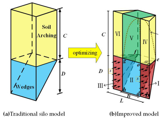
Figure 3.
Calculation model.
The damage mechanism discussed in this paper is that, in ultimate equilibrium, the overburden load is equal to the load carrying capacity of the wedge; when the load applied to the wedge (block II) by the overburden (block V) exceeds the force such that the wedge can no longer withstand it at the boundary of the wedge, the wedge will reach its ultimate state and break. The load applied by the overburden layer (Vsilo) is calculated by the silo theory [33]; the load carrying capacity of the wedge is calculated by the horizontal strip method [33], where the relevant shear force is discounted [32] by Equation (1); and then the corresponding safety factor is obtained by the ultimate equilibrium analysis.
In ultimate equilibrium, the overburden load is equal to the load-carrying capacity of the wedge; when the load applied to the wedge (block II) by the overburden (block V) exceeds the force that the wedge can withstand at its boundary, the wedge reaches its ultimate state and fails. The load applied by the overburden layer (Vsilo) is computed using the silo theory [33]; the load carrying capacity of the wedge is computed using the horizontal strip method [33], where the relevant shear force is discounted [32] by Equation (1); and then the corresponding safety factor is obtained using the ultimate equilibrium analysis:
where is the maximum shear strength of the soil, and represents the actual exerted shear strength.
As shown in Figure 4, considering the equilibrium of an infinitesimal slice with thickness dz, forces acting on the slice include the self-weight dG; the resultant “supporting” force V(z) exerted by the underlying ground bcgf; the resultant “loading” force V(z) + dV exerted by the overlying ground adhe; the resultant normal force dN and shear force dT at the inclined slip surface cdhg; and the resultant shear force dTs at the two vertical slip surfaces abcd and efgh. The equations of static equilibrium of the slice in the x and y directions can be respectively expressed as:
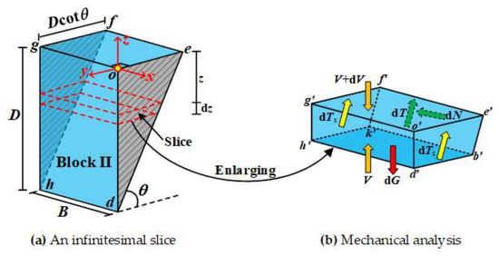
Figure 4.
Forces acting upon an infinitesimal slice.
Self-weight dG is
where γ is the weight of the soil, dA is the slice side area, and
The maximum shear strength of the inclined sliding surface cdhg is
From the idea of strength discounting (Equation (1)), the actual shear force can be found to be
From Equation (7), the actual shear force on the inclined sliding surface cdhg is
The maximum shear strength of the vertical sliding surface abcd (efgh) on both sides is
From Equation (7), the actual shear force on the vertical sliding surface abcd (efgh) on both sides is
where is the lateral pressure coefficient of the soil, and , is the vertical stress, taking into account Equation (5):
It is possible to obtain
By substituting Equations (2), (4), (5), (8), and (12) into Equation (3), the equilibrium equation parallel to the inclined plane cdhg can be obtained:
of which
of which
Equation (12), which is a differential equation of vertical stress combined with boundary conditions, can be obtained:
of which
Another boundary condition for the differential equation of vertical stress is , of which
The load applied by the overburden is
where is the surface load, assumed to be 0 in this paper; and R equals the ratio of the volume of the soil column to its circumferential area, which is
From the boundary conditions and Equations (21) and (22), we obtain
When the soil strength (,) and tunnel dimensions (C, L, D and B) are given, and in Equation (24) are mutual functions and inverse functions, respectively. This paper uses MATHEMATICA programming to solve the numerical method for the safety factor .
3. Results
Parametric Analysis
The influence of soil shear strength parameters (,), tunnel geometry parameters (,), and open silo parameters (unsupported ratio ) on the stability was analyzed. The calculation parameters are shown in Table 1.

Table 1.
Calculation parameters.
As shown in Table 2, when and is 1.5 and 2, respectively, and change with . It can be seen that, as increases, increases, and increases, indicating that the increase in the self-stabilization capacity of the soil causes the volume of the damage area to decrease, and the safety factor is increased. When and are certain, the larger that is, the smaller that is. For example, with = 1.5, = 30, the increase in B/L is from 0.45 to 0.75, and a decrease in fs occurs of approximately 21.9%, which is due to the increase in the risk of instability of the working face caused by the increase in the unsupported area.

Table 2.
Variation of the optimal and depending on .
As shown in Figure 5, increases with when other conditions are certain. For example, with and , when increased from 20° to 40°, increased by approximately 32.0% because, as the angle of internal friction increases, so does the shear strength of the tunnel’s surrounding rock and the tunnel’s capacity for self-stabilization, which are conducive to maintaining stability. Comparing Figure 5a,b, it can be seen that decreases slightly with increasing depth of overburden when is a constant because the greater that the burial depth is, the greater that the overburden pressure is, and consequently, the greater that the potential for it to destabilize is.
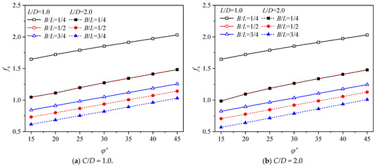
Figure 5.
Variations in depending on ( ).
Based on the numerical calculations and the strength reduction technique, Vermeer et al. [36] proposed a simple analytical equation to calculate the safety factor for open face tunneling as follows
where , , and are the soil cohesion, friction angle, and soil unit weight, respectively; and d is the unlined distance behind the tunnel face and is taken as 0 in this paper. Using D as the equivalent diameter of a noncircular section, this article calculates the height of the pipe-jacking machine. This section compares the current solution with Liu’s solutions and Vermeer’s equation for verification. In the theoretical model of Liu [37], obtained under the same conditions is brought into the procedure to calculate the safety factor for the model and to use it to check against the solution in this paper.
The variation of with L/D for the case of is given in Figure 6. It is easy to see that both Liu’s solution and the model solution of this paper have a safety factor that decreases with increasing L/D, also verifying the accuracy of Figure 5. The safety factor obtained from Liu’s solution is greater than that of the model solution of this paper in all operating conditions, indicating that the solution of this paper provides a safer solution and is more conducive to providing suggestions for engineering. When L/D = 2.0, the safety factors of the two models are very close, while when L/D is smaller, the difference between the two model solutions is larger, indicating that both are equally adaptable for larger width-to-height ratios. In the case of C/D = 2.0, the coefficient of safety of the paper solution decreases by 20%, while Liu’s solution decreases by about 47% as L/D decreases from 1.0 to 1.5, indicating that Liu’s solution is more sensitive to L/D compared to the paper’s model. Observing Figure 6a,b, it can be seen that the safety coefficient pattern is the same, also verifying the reliability of the change pattern. The results obtained from Vermeer’s equation are closer to the solution of this paper at a larger L/D, also illustrating the reliability of the solution of this paper at high L/D.
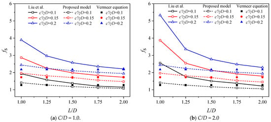
Figure 6.
Variations in depending on L/D (Liu et al. [37]).
As shown in Figure 7, when and , shows a non-linear and significant decrease as increases, indicating that is strongly influenced by . Considering and as examples, increases from 0.2 to 0.8, and decreases by 45.7% because the larger that the empty bin area is, the more soil that loses support, and the more likely that it is to slide out of stability. Comparing Figure 7a,b, it can be seen that decreases as increases for a given because an increase in working face width indirectly results in a larger void area and diminishes the soil arch effect, thereby increasing the risk of instability. The most unfavorable conditions shown at and have a safety factor of less than 1 when the soil quality is poor. Since Vermeer’s equation does not account for open positions, the results do not correspond to variations in .
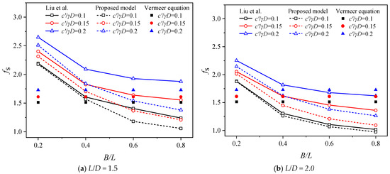
Figure 7.
Variations in depending on (Liu et al. [37]).
As shown in Figure 8, it can be seen that, as increases, shows a near linear increase, and Liu’s solution is more sensitive with respect to the parameters. In addition, it can be observed that the slope of the solution to Vermeer’s equation is identical to the slope of the solution presented in this paper; both are linearly increasing. Given that Vermeer’s equation is B/L-independent, a line is sufficient here. Figure 8a,b demonstrate that an increase in the soil’s self-stabilization capacity (increase in cohesion and increase in friction angle) leads to a decrease in the volume of the damaged area and an increase in the safety factor. In Figure 8a, when , , the solution of this paper and Liu’s solution give almost the same safety factor, but the difference gradually increases with the increase in the friction angle.
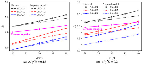
Figure 8.
Variations in depending on (Liu et al. [37]).
4. Discussion
In this section, the theoretical solution of this paper is verified based on an underground passage attached to a station of Suzhou Line 5 [37]. As shown in Figure 9, the rectangular tunnel was constructed by the jacking method with a cross-sectional dimension of 6.9 m × 4.2 m. The tunnel length was about 62.8 m, and the overburden depth was about 4.5 m. A total of 42 rings were jacked by the rectangular jacking method. The rectangular boring machine used six independent spoked cutters for excavation and a double screw conveyor for soil discharge. The main soil layers traversed by the tunnel were: ①1 the fill layer and ③1 the powder clay layer, and the lower lying soil layer was ③3 powder clay with powder sand layer. The physical and mechanical properties of each soil layer are shown in Table 3.
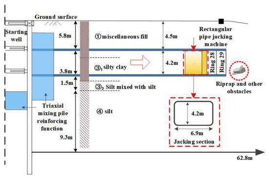
Figure 9.
Opening and clearing of a rectangular jacking pipe in Suzhou.

Table 3.
Soil properties.
The rectangular roadheader stops and opens the position when it encounters obstacles such as thrown rocks while advancing 28 and 29 rings, as shown in Figure 10. Three surface settlement monitoring points were set up at 42 m from the start shaft (1.5 m per ring), i.e., above the position between the pipe pieces of rings 28 and 29, at the position of the axis (here referring to monitoring point K2 on the drawing) and 4 m from both sides of the axis (here referring to monitoring points K1 and K3 on the drawing), as shown in Figure 11, and they were monitored once per day. A number of drift stones, up to 50 cm in size, were removed by opening the silo for clearance, as shown in Figure 12. The maximum settlement was about 21 cm at monitoring point K2 on the axis and about 9 cm at monitoring points K1 and K3 on both sides of the axis. According to the engineering conditions, we set the opening ratio as 0.35 and substituted the actual conditions of each project into the formula of this paper. The safety factor of this project can be calculated according to Section 2.1. The results are shown in Table 4.
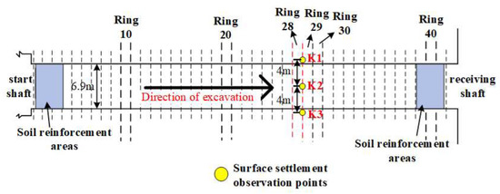
Figure 10.
Layout of a project in Suzhou.
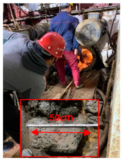
Figure 11.
Boulder removal.
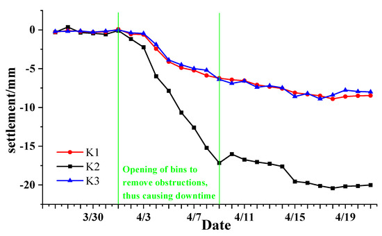
Figure 12.
Surface settlement during opening.

Table 4.
Comparison of calculated and monitored values.
During the normal digging phase, the support pressure varied between 65 kPa and 78 kPa. During normal pressure opening during shutdown, the residual support pressure on both sides ranged from 58 kPa to 67 kPa. Due to the small number of openings, the high risks involved, and the limited construction site conditions, ground stability was mainly judged by surface settlement. Although surface settlement occurred during the opening process, the settlement was less than 30 mm, the development of the ground deformation tended to be smooth, and the pressure was sufficient to maintain ground stability. The actual engineering situation fitted the presumed safety factor of 2.1 in this paper, and the comparison verified the reliability of the current model.
5. Conclusions
This paper presents a theoretical study of the stability of rectangular tunnel boring faces, and by employing parameter analysis, the influence of various factors on the stability was investigated. The theoretical method was then applied to the Suzhou project for verification, and the model’s reliability was evaluated. The following conclusions are reached:
- (1)
- A silo-wedge model is used to analyze the instability zone under low pressure or no support conditions for the problem of uneven pressure fluctuations at the palm face. This is a new method for calculating the safety factor of the excavated face. In the analysis, the unstable wedge is horizontally striped, and the concept of strength reduction is introduced into the limit equilibrium analysis to derive the safety factor for the unstable zone. The implicit expression of the safety factor is then solved using the mathematical software MATHEMATICA.
- (2)
- A parametric analysis of the soil strength parameters and tunnel geometry parameters was performed using the solutions of this paper, showing that decreases as the open area increases because the larger that the open area is, the more soil that loses support, and the more likely that it is to slide out of stability. It is important to note that, when the opening ratio is greater than 0.75 and the friction angle within the soil is less than 20°, the safety factor is less than 1, and the risk is greater. increases as increases because the shear strength of the tunnel envelope increases, and the more self-stabilizing that it is, the better that it is for maintaining stability. decreases slightly with increasing depth of burial because the greater that the depth of burial is, the greater that the overburden pressure is, and therefore, the greater that the susceptibility to instability and slumping is. Such a variation law is also consistent with Liu’s solution and Vermeer’s formula.
- (3)
- The solution of this paper is applied to the actual project, and the safety coefficient of the stability of the working face is calculated under the specific project-opening situation, verifying the reliability of this paper’s solution. The paper proves that the solution can serve as a theoretical reference for additional projects of a similar type.
Author Contributions
Conceptualization, X.Z. and W.L.; methodology, M.Y. and J.L.; validation, M.Y., C.Y. and X.Z.; investigation, J.L.; writing—original draft preparation, X.Z.; writing—review and editing, W.L., C.Y. and X.Z.; supervision, W.L. All authors have read and agreed to the published version of the manuscript.
Funding
This research was funded by the National Natural Science Foundation of China under grant number 51978430; Power China Huadong Engineering Corporation Limited (KY2019-ZD-02); the Key R&D Program of Zhejiang Province (2019C03111).
Institutional Review Board Statement
Not applicable.
Informed Consent Statement
Not applicable.
Data Availability Statement
The data presented in this study are available upon request from the corresponding authors.
Conflicts of Interest
The authors declare no conflict of interest.
Abbreviations
The following symbols are used in this paper:
| height of tunnel | |
| width of tunnel | |
| cover depth | |
| width of partially supported area | |
| effective cohesion | |
| effective angle of internal friction | |
| total unit weight | |
| ground surcharge | |
| support force acting on block I | |
| support force acting on block II | |
| wedge angle between slanted failure plane and horizontal | |
| lateral stress coefficient | |
| active earth pressure coefficient | |
| ratio of volume of prism to its side area | |
| load applied by overburden |
References
- Davis, E.H.; Gunn, M.J.; Mair, R.J.; Seneviratne, H.N. The stability of shallow tunnels and underground openings in cohesive material. Géotechnique 1980, 30, 397–416. [Google Scholar] [CrossRef]
- Leca, E.; Dormieux, L. Upper and lower bound solutions for the face stability of shallow circular tunnels in frictional material. Géotechnique 1990, 40, 581–606. [Google Scholar] [CrossRef]
- Mollon, G.; Dias, D.; Soubra, A.H. Rotational failure mechanisms for the face stability analysis of tunnels driven by a pressurized shield. Int. J. Numer. Anal. Methods 2011, 35, 1363–1388. [Google Scholar] [CrossRef]
- Pan, Q.J.; Dias, D. Upper-bound analysis on the face stability of a non-circular tunnel. Tunn. Undergr. Space Technol. 2017, 62, 96–102. [Google Scholar] [CrossRef]
- Liu, W.; Shi, P.X.; Chen, L.J.; Tang, Q. Analytical analysis of working face passive stability during shield tunneling in frictional soils. Acta Geotech. 2020, 15, 781–794. [Google Scholar] [CrossRef]
- Liu, W.; Wu, B.; Shi, P.X.; Cai, G.Q. Upper bound analysis of working face passive failure in large-diameter shield tunneling based on a composite mechanism. Comput. Geotech. 2021, 138, 104362. [Google Scholar] [CrossRef]
- Soubra, A.H.; Regenass, P. Three-dimensional passive earth pressures by kinematical approach. J. Geotech. Geoenviron. 2000, 126, 969–978. [Google Scholar] [CrossRef]
- Mollon, G.; Dias, D.; Soubra, A.H. Continuous velocity fields for collapse and blow-out of a pressurized tunnel face in purely cohesive soil. Int. J. Numer. Anal. Methods 2013, 37, 2061–2083. [Google Scholar] [CrossRef]
- Senent, S.; Yi, C.K.; Jimenez, R. An upper bound solution for tunnel face stability analysis considering the free span. Tunn. Undergr. Space Technol. 2020, 103, 103515. [Google Scholar] [CrossRef]
- Gao, J.; Zhang, Y.T.; Qiao, J.L. Face stability analysis of tunnels with consideration of seepage force. Chin. J. Geotech. Eng. 2009, 31, 1547–1553. (In Chinese) [Google Scholar]
- Chen, R.P.; Qi, L.Z.; Tang, L.J.; Zhou, B.S. Study of limit supporting force of excavation face’s passive failure of shield tunnels in sand strata. Chin. J. Rock Mech. Eng. 2013, 32, 2877–2882. (In Chinese) [Google Scholar]
- Lv, X.L.; Li, F.D.; Huang, M.S.; Wan, J.L. Three-dimensional numerical and analytical solutions of limit support pressure at shield tunnel face. J. Tongji Univ. (Nat. Sci.) 2012, 40, 1469–1473. (In Chinese) [Google Scholar]
- Perazzelli, P.; Leone, T.; Anagnostou, G. Tunnel face stability under seepage flow conditions. Tunn. Undergr. Space Technol. 2014, 43, 459–469. [Google Scholar] [CrossRef]
- Chambon, P.; Corte, J. Shallow Tunnels in Cohesionless Soil: Stability of Tunnel face. Int. J. Geotech. Eng. 1994, 120, 1148–1165. [Google Scholar] [CrossRef]
- Chen, R.P.; Li, J.; Chen, Y.M.; Kong, L.G. Large-scale tests on face stability of shield tunnelling in dry cohesionless soil. Chin. J. Geotech. Eng. 2011, 33, 117–122. (In Chinese) [Google Scholar]
- Chen, R.P.; Li, J.; Kong, L.G.; Tang, L.J. Experimental study on face instability of shield tunnel in sand. Tunn. Undergr. Space Technol. 2013, 33, 12–21. [Google Scholar] [CrossRef]
- Ng, C.W.W.; Wong, K.S. Investigation of passive failure and deformation mechanisms due to tunnelling in clay. Can. Geotech. J. 2013, 50, 359–372. [Google Scholar] [CrossRef]
- Liu, W.; Zhao, Y.; Shi, P.X.; Li, J.Y.; Gan, P.L. Face stability analysis of shield driven tunnels shallowly buried in dry sand using 1 g large-scale model tests. Acta Geotech. 2018, 13, 693–705. [Google Scholar] [CrossRef]
- Horn, N. Horizontal earth pressure on the vertical surfaces of the tunnel tubes. In Proceedings of the National Conference of the Hungarian Civil Engineering Industry, Budapest, Hungary, 18–21 June 1961; pp. 7–16. [Google Scholar]
- Janssen, H.A. Versuche fiber Getreidedruck in Silozellen. Z. Des Ver. Dtsch. Ing. 1895, 39, 1045–1049. [Google Scholar]
- Jancsecz, S.; Steiner, W. Face support for a large mix-shield in heterogeneous ground conditions. In Proceedings of the Tunnelling 1994, London, UK, 5–7 July 1994; Springer: Boston, MA, USA, 1994; pp. 531–550. [Google Scholar]
- Nv, M.N.; Broere, W.; Bosch, J. The impact of shallow cover on stability when tunnelling in soft soils. Tunn. Undergr. Space Technol. 2015, 50, 507–515. [Google Scholar]
- Chen, R.P.; Lin, X.T.; Wu, H.N. An analytical model to predict the limit support pressure on a deep shield tunnel face. Comput. Geotech. 2019, 115, 103174. [Google Scholar] [CrossRef]
- Anagnostou, G.; Kovari, K. The face stability of slurry-shield-driven tunnels. Tunn. Undergr. Space Technol. 1994, 9, 165–174. [Google Scholar] [CrossRef]
- Anagnostou, G.; Kovari, K. Face stability conditions with earth-pressure-balanced shields. Tunn. Undergr. Space Technol. 1996, 11, 165–173. [Google Scholar] [CrossRef]
- Broere, W. Face stability calculation for s slurry shield in heterogeneous soft soils. Tunn. Metrop. 1998, 23, 215–218. [Google Scholar]
- Wei, G. Theoretical Study on Properties of Soil and Structure during Pipe Jacking Construction. Ph.D. Thesis, Zhejiang University, Hangzhou, China, 2005. [Google Scholar]
- Wei, G.; He, F. Calculation of minimal support pressure acting on shield face during pipe jacking in sandy soil. Chin. J. Undergr. Space Eng. 2007, 3, 903–908. (In Chinese) [Google Scholar]
- Lei, M.F.; Peng, L.M.; Shi, C.H.; Zhao, D. Calculation and analysis of limit support force of shield tunnel excavation face under facing-slope conditions. Chin. J. Rock Mech. Eng. 2010, 32, 488–492. (In Chinese) [Google Scholar]
- Xu, Y.J.; Liang, W.Z.; Liu, X.M.; Cui, G.Q.; Bai, X.G. Soil Mass Stability at the Working Face of a Rectangular Pipe-Jacking Tunnel with a Large Section. Mod. Tunn. Technol. 2017, 54, 70–85. (In Chinese) [Google Scholar]
- Cheng, C.; Zhao, W.; Cheng, C.N.; Li, F. Calculation on Active Limit Support Pressure of Shield Tunnel Excavation Face in Dry Cohesionless Soil. J. Northeast. Univ. (Nat. Sci.) 2018, 39, 1348–1352. (In Chinese) [Google Scholar]
- Zhang, X.; Wang, M.N.; Li, J.W.; Tong, J.J.; Liu, D.G. Safety factor analy sis of a tunnel face with an unsupported span in cohesive-frictional soils. Comput. Geotech. 2020, 117, 103221. [Google Scholar] [CrossRef]
- Anagnostou, G. The contribution of horizontal arching to tunnel face stability. Géotechnique 2012, 35, 34–44. [Google Scholar] [CrossRef]
- Paternesi, A.; Schweiger, H.F.; Scarpelli, G. Numerical analyses of stability and deformation behavior of reinforced and unreinforced tunnel faces. Comput. Geotech. 2017, 88, 256–266. [Google Scholar] [CrossRef]
- Yu, M.; Liu, W.; Wu, B.; Yan, J.; Gan, P. Working Face Stability of Box Shield Tunneling under Non-Uniform Support Pressure. Appl. Sci. 2022, 12, 12360. [Google Scholar] [CrossRef]
- Vermeer, P.A.; Ruse, N.; Marcher, T. Tunnel heading stability in drained ground. Felsbau 2002, 20, 8–18. [Google Scholar]
- Liu, W.; Shi, P.X.; Yu, M.; Jia, P.J. Analysis of working face stability during obstruction removal from a box tunnel machine. Acta Geotech. 2022, 17, 4627–4639. [Google Scholar] [CrossRef]
Disclaimer/Publisher’s Note: The statements, opinions and data contained in all publications are solely those of the individual author(s) and contributor(s) and not of MDPI and/or the editor(s). MDPI and/or the editor(s) disclaim responsibility for any injury to people or property resulting from any ideas, methods, instructions or products referred to in the content. |
© 2023 by the authors. Licensee MDPI, Basel, Switzerland. This article is an open access article distributed under the terms and conditions of the Creative Commons Attribution (CC BY) license (https://creativecommons.org/licenses/by/4.0/).