
Design and Mechanical Properties of Flat Anchorage Limit Plate

 , ,
, ,
Abstract
:1. Introduction
2. Design of Flat Anchorage Limit Plate
2.1. Application Background of Limit Plate
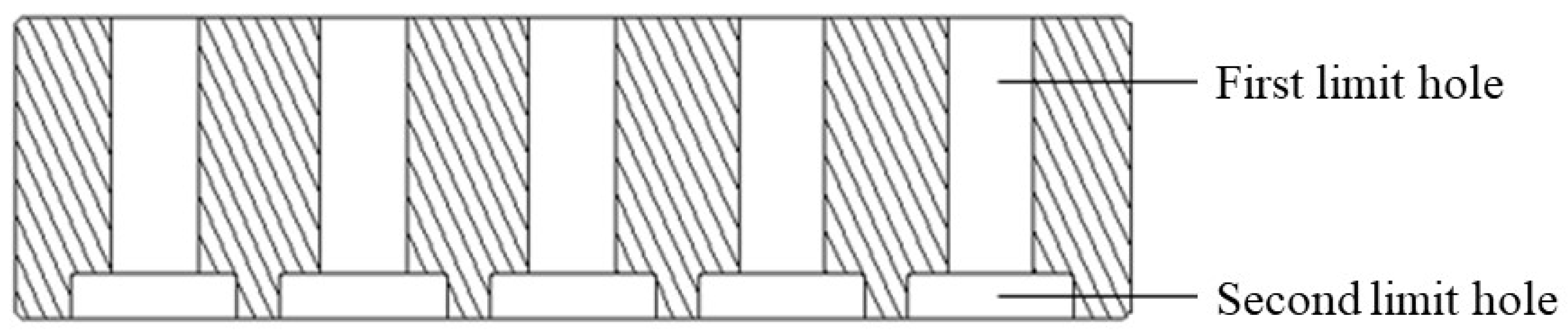
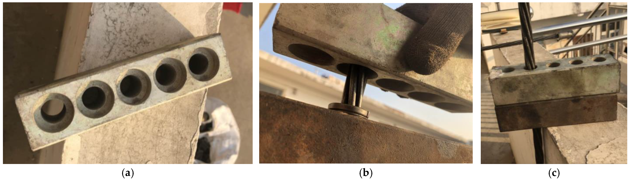
2.2. Limit Plate Design
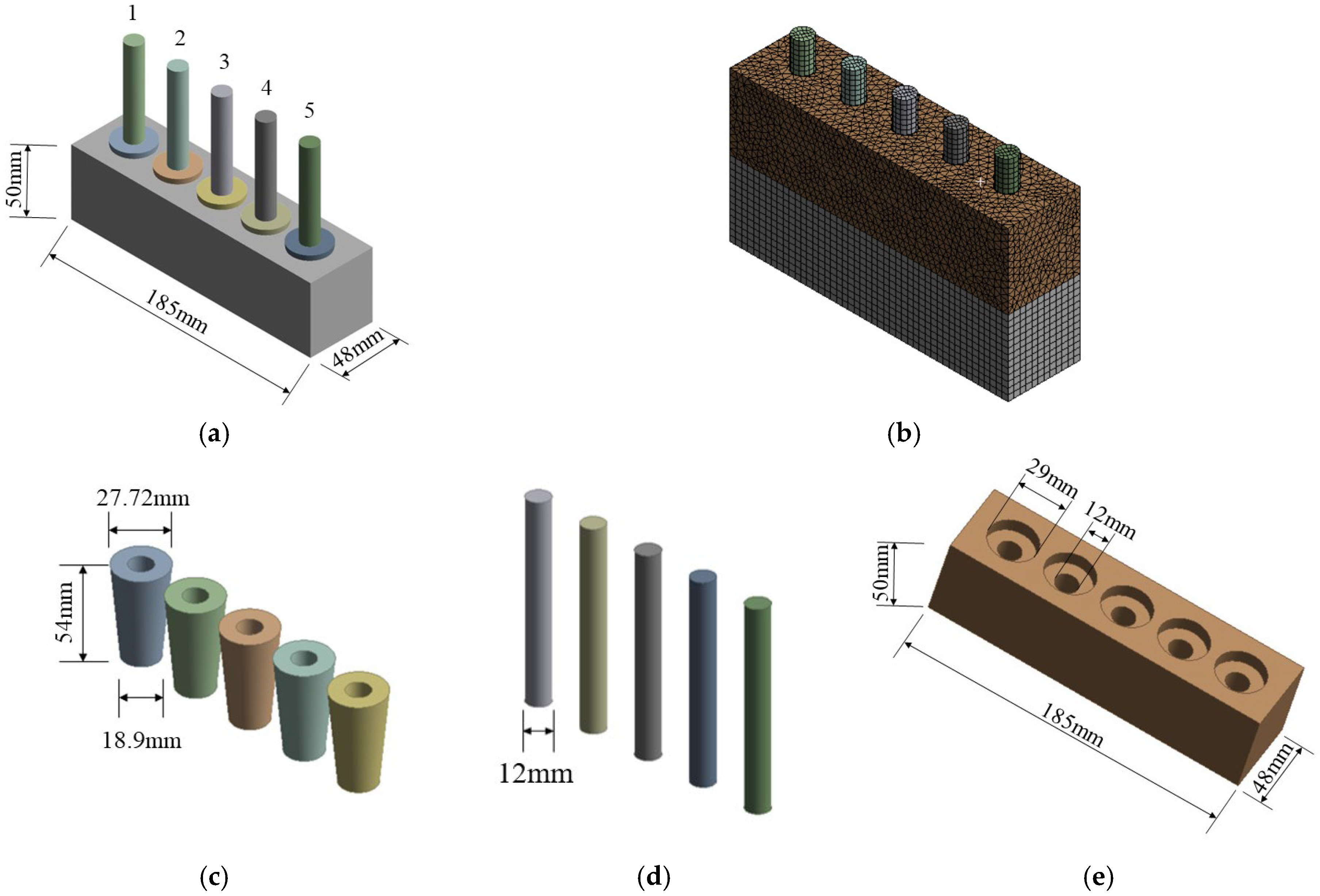
3. Establishment of Numerical Model of Flat Anchorage
4. Mechanical Properties of Flat Anchorage Limit Plate
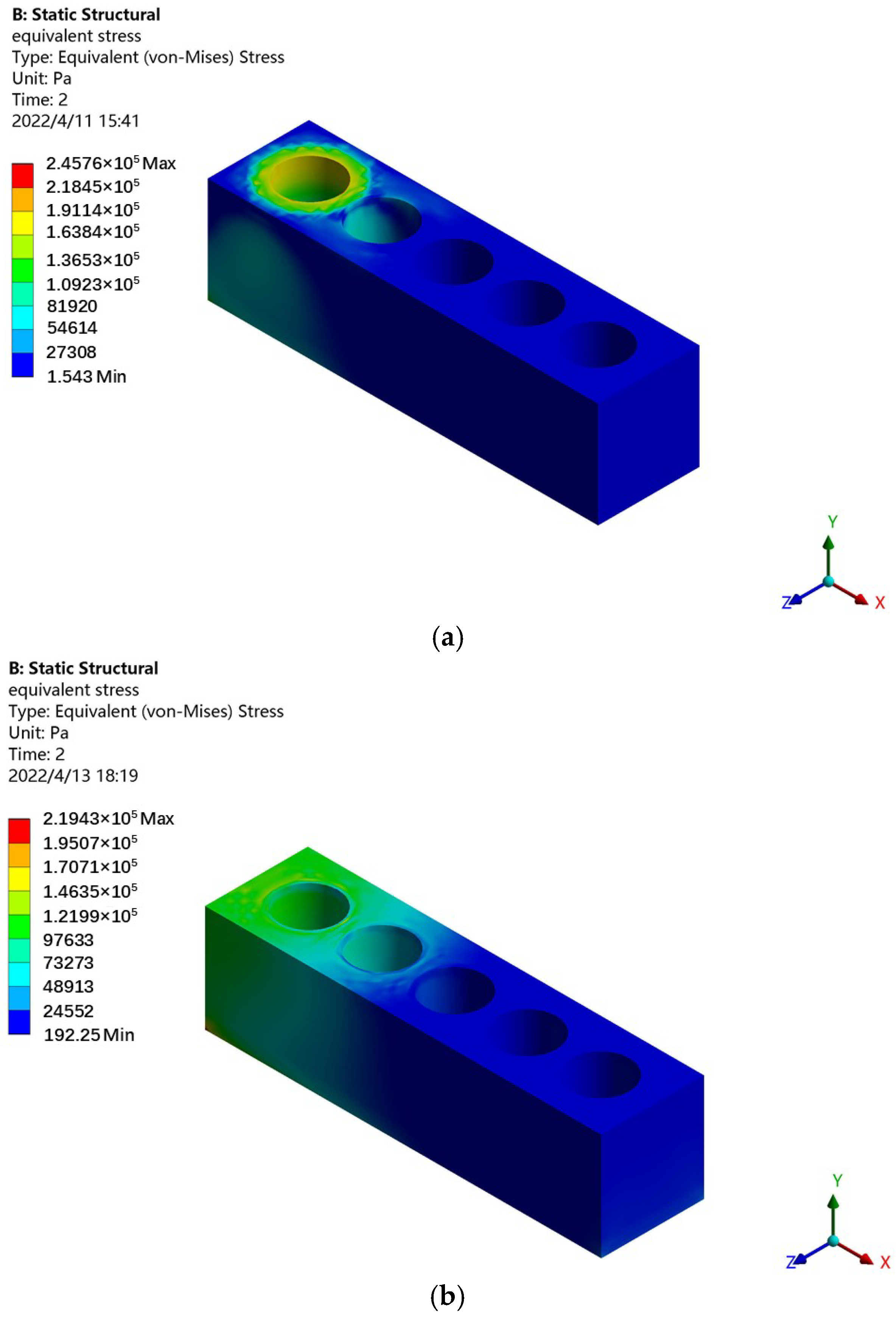
4.1. Tensile Stress Distribution of Single Hole
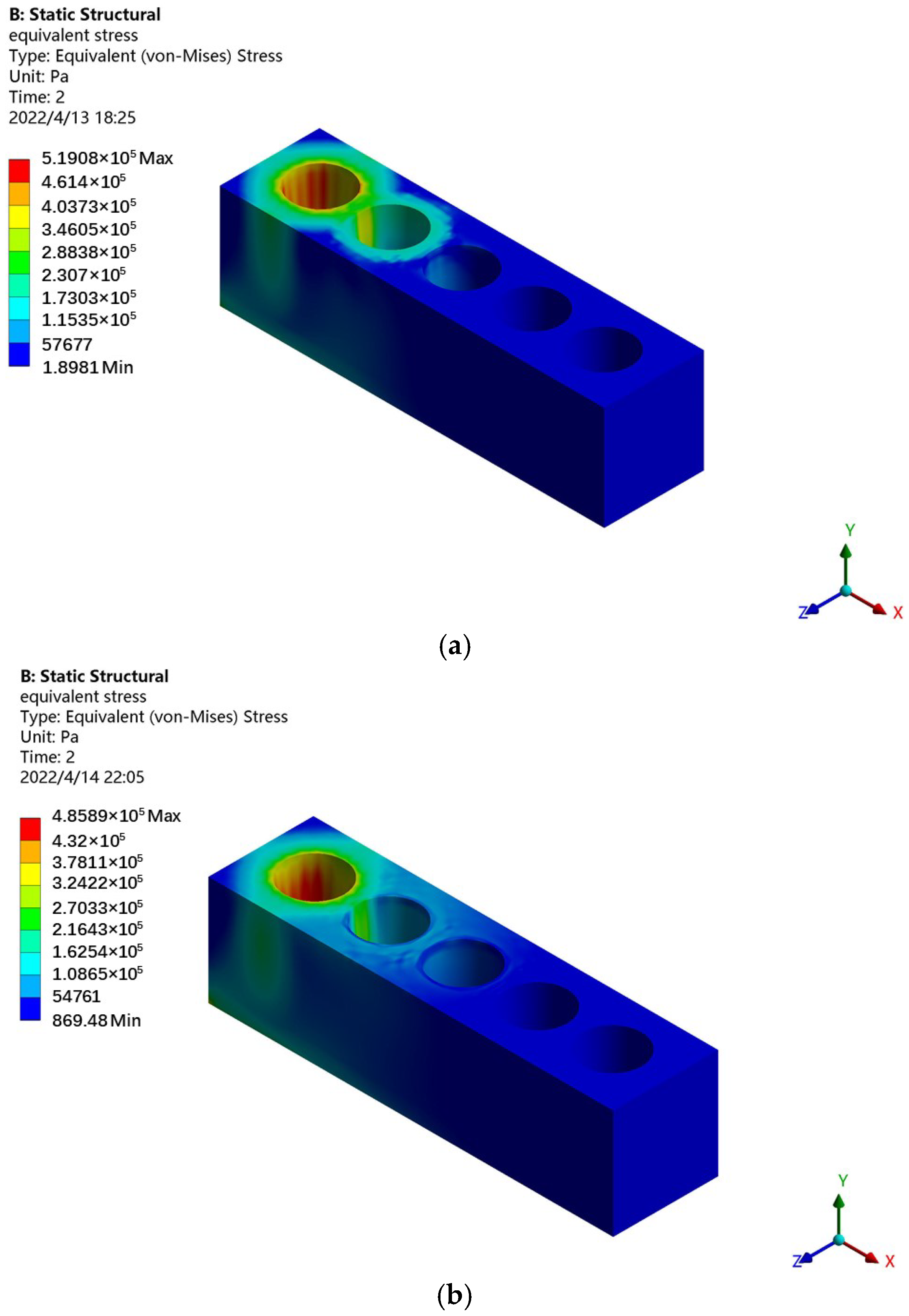
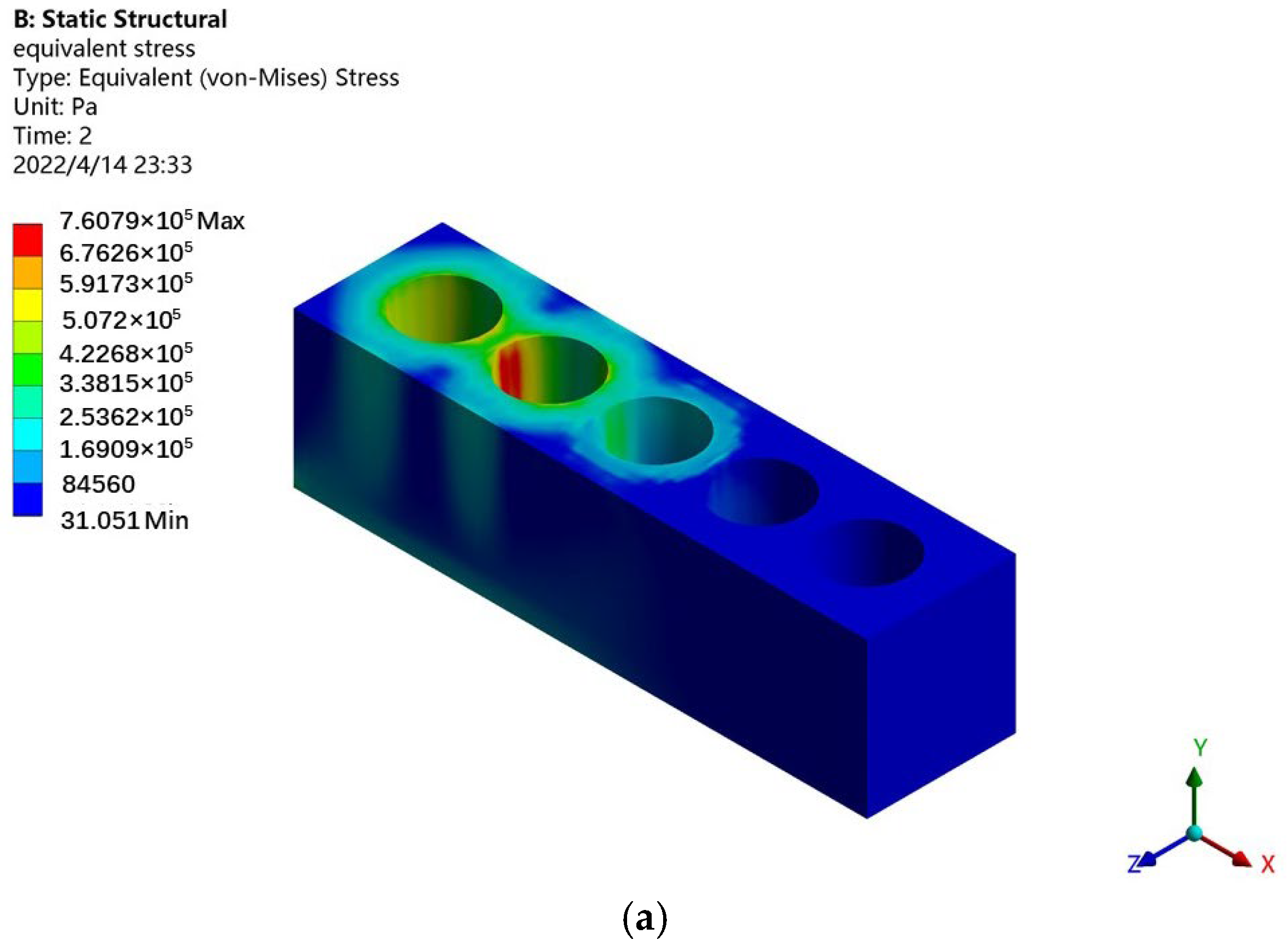
4.2. Tensile Stress Distribution of Double Holes
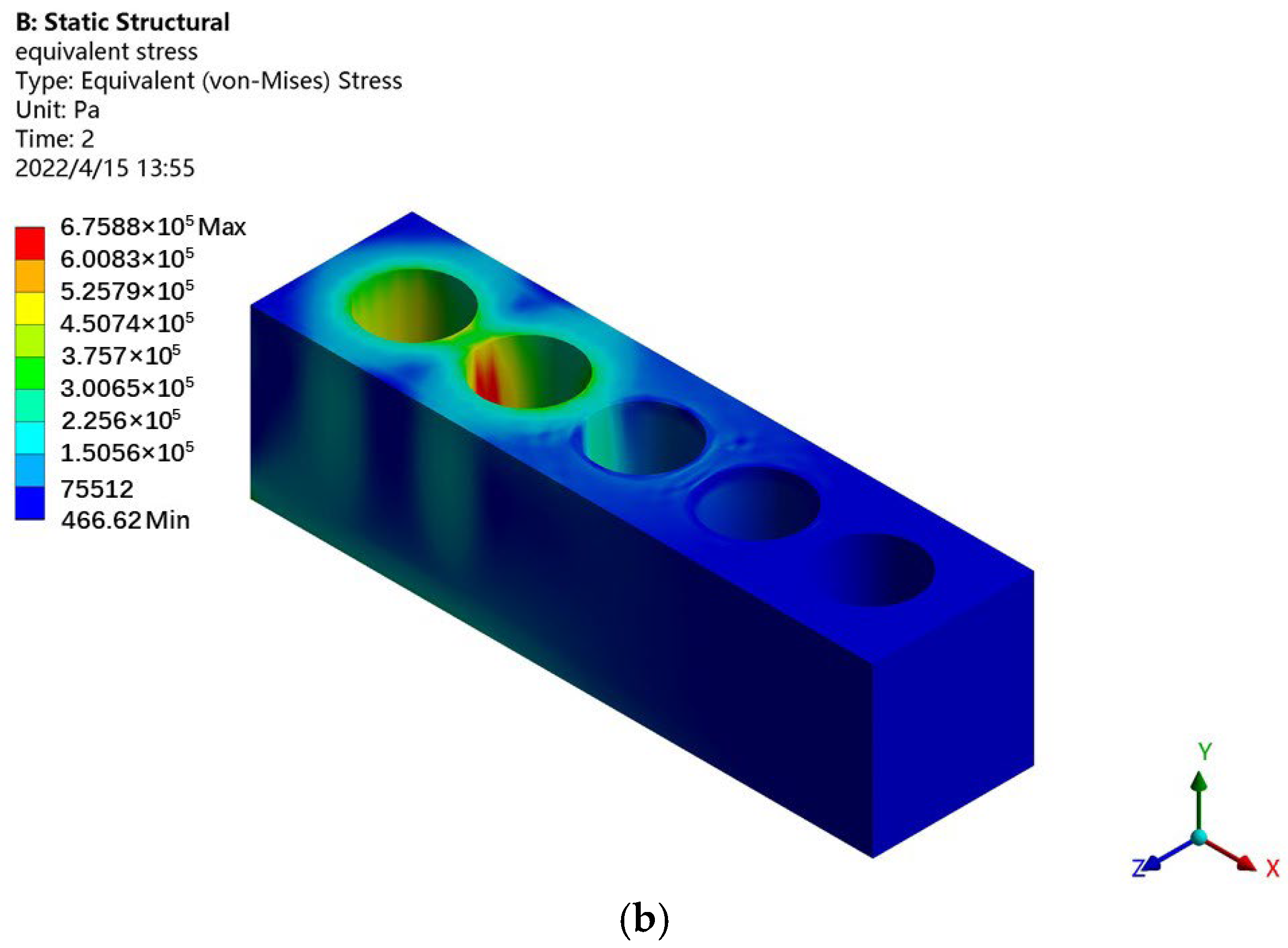
4.3. Three-Hole Tensile Stress Distribution
4.4. Four-Hole Tensile Stress Distribution
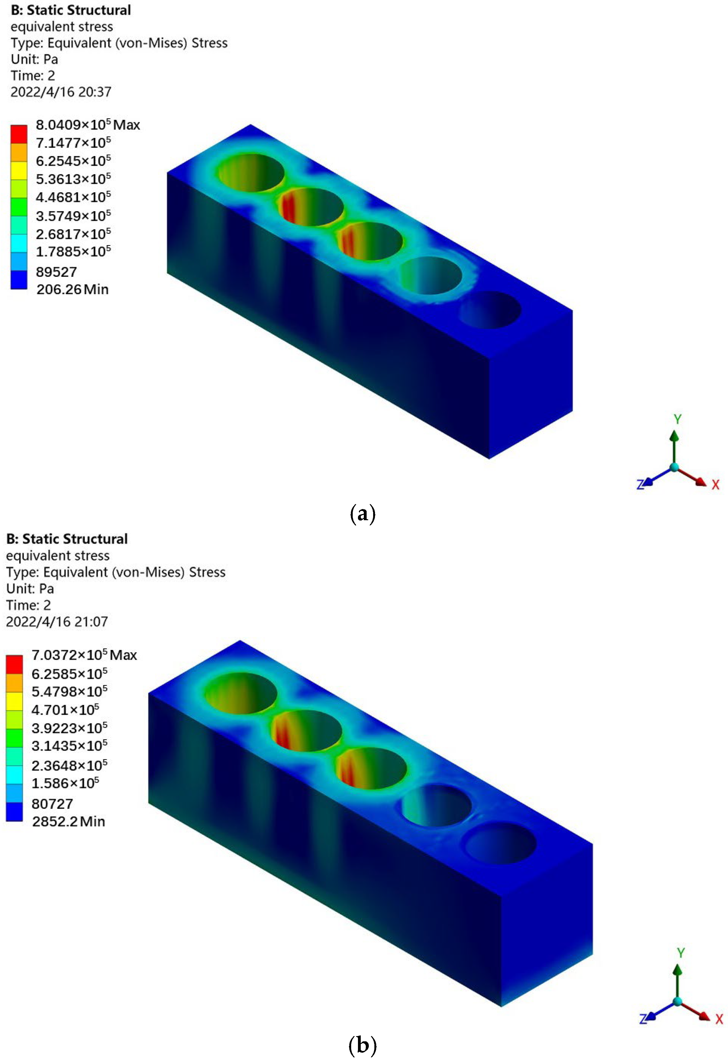
4.5. Five-Hole Tensile Stress Distribution
5. Construction Site Application
6. Conclusions
Author Contributions
Funding
Institutional Review Board Statement
Informed Consent Statement
Data Availability Statement
Conflicts of Interest
References
- Hu, J.; Zheng, Q. Application of 2000 MPa Parallel Wire Cables to Cable-Stayed Rail-cum-Road Bridge with Main Span Length over 1000 m. Bridge Constr. 2019, 49, 48–53. [Google Scholar]
- Wu, Y.; Ya, G.; Dai, X.; Zhang, X. Key Techniques of 1960 MPa Steel Wire and Wire Strand for Main Cable of Second Humen Bridge. Bridge Constr. 2018, 48, 5–10. [Google Scholar]
- Wu, Q.; Qiang, Q.; Zhou, Z.; Wang, Z.; Zhou, N. Study of Anchorage Design for 1860 MPa-Grade Stay Cables of Qingshan Changjiang River Highway Bridge in Wuhan. Bridge Constr. 2020, 50, 106–111. [Google Scholar]
- Wang, N. Hoop Prestressing Technique on Pylons of Wuhu Changjiang River Rail-cum-road Bridge on Shangqiu-Hefei-Hangzhou Railway. Bridge Constr. 2019, 49, 7–12. [Google Scholar]
- Li, J.; Zhou, W. Construction Techniques for Stay Cables Provided with Isodirectionally Turning Stay Cable Anchor System. Bridge Constr. 2015, 45, 110–115. [Google Scholar]
- Yang, Z.; Tan, T.; Liu, Y.; Sun, M.; Zhang, Y. Experimental Study on Prestressed CFRP Reinforced Concrete Slab. J. Highw. Transp. Res. Dev. 2017, 34, 76–82. [Google Scholar]
- Zhang, B.; Shang, S. Experimental Study on Flexural Member Strengthened with Variable Bonded Prestressed CFRP Plates. J. Highw. Transp. Res. Dev. 2018, 35, 61–68. [Google Scholar]
- Guo, R.; Peng, Z.; Guo, J.; Du, L.; Zhao, S. Experimental and Theoretical Analysis on Bending Fatigue Performance of RC Beam Reinforced with Bonded Prestressed CFRP Plate. J. Highw. Transp. Res. Dev. 2018, 35, 50–57+85. [Google Scholar]
- Shang, S.; Zhang, B.; Lv, X. Experimental Study on Long-term Creep Behavior of Beam Bridge Strengthened with Prestressed CFRP Plate. J. Highw. Transp. Res. Dev. 2015, 32, 68–74. [Google Scholar]
- Viktor, G.; Aleksandr, K.A.; Arvydas, R. An Innovative Frictional Anchorage System for Flat CFRP Ribbon Strips. Compos. Struct. 2023, 303, 116369. [Google Scholar]
- Damiani, M.; Quadrino, A.; Nisticò, N. FRP Cables to Prestress RC Beams: State of the Art vs. a Split Wedge Anchorage System. Buildings 2021, 11, 209. [Google Scholar] [CrossRef]
- Shakiba, M.; Oskouei, A.V.; Karamloo, M.; Doostmohamadi, A. Effect of Mat Anchorage on Flexural Bonding Strength Between Concrete and Sand Coated GFRP Bars. Compos. Struct. 2021, 273, 114339. [Google Scholar] [CrossRef]
- Zwingmann, B.; Liu, Y.; Schlaich, M.; Janetzko, S. The sling anchorage: Approach to Anchor the Full Load Bearing Capacity of Pin-loaded Straps. Compos. Struct. 2017, 178, 110–118. [Google Scholar] [CrossRef]
- Xiao, X.; Zhang, Q.; Zheng, J.; Li, Z. Analytical model for the nonlinear buckling responses of the confined polyhedral FGP-GPLs lining subjected to crown point loading. Eng. Struct. 2023, 282, 115780. [Google Scholar] [CrossRef]
- Xiao, X.; Zhang, H.; Li, Z.; Chen, F. Effect of Temperature on the Fatigue Life Assessment of Suspension Bridge Steel Deck Welds under Dynamic Vehicle Loading. Math. Probl. Eng. 2022, 2022, 7034588. [Google Scholar] [CrossRef]
- Deng, E.; Zhang, Z.; Zhang, C.; Tang, Y.; Wang, W.; Du, Z.; Gao, J. Experimental study on flexural behavior of UHPC wet joint in prefabricated multi-girder bridge. Eng. Struct. 2023, 275, 115314. [Google Scholar] [CrossRef]
- Abedini, M.; Zhang, C. Residual capacity assessment of post-damaged RC columns exposed to high strain rate loading. Steel Compos. Struct. 2022, 45, 389–408. [Google Scholar]
- Zhong, X.; Shu, X.; Yao, F.; Yuan, Y.; Wang, G. Research on Tangential Stiffness Identification of the Rough Interface between Anchor and Anchor Plate. Chin. J. Appl. Mech. 2017, 34, 384–389+412. [Google Scholar]
- Shi, L.; Ma, L.; Chen, S.; Su, Y. Research on High-strength Prestressed Anchorage System Technology of Railway Bridge. Railw. Eng. 2021, 61, 1–4+39. [Google Scholar]
- Zhang, C.; Zha, H.; Wang, X.; Wang, H.; Li, B. Key Points of Deepening Design of Large-span Prestressed Beamless Floor and Construction Technical Measures. Build. Struct. 2021, 51, 2277–2280. [Google Scholar]
- Du, Y.; Tang, Z. Anchorage Mechanism of Fiber Yarn with Impregnated Inorganic Glue. Highw. Eng. 2021, 46, 41–46. [Google Scholar]
- Sun, S.; Zhao, L.; Mei, K.; Li, H.; Xing, L. Experimental Study on Tensile Properties of Steel-basalt Fiber Composite Bars. J. Highw. Transp. Res. Dev. 2021, 38, 45–50+95. [Google Scholar]
- Fei, H.; Shan, J.; Ma, W.; Wang, Z. Design and Anchorage Performance Test of Anchorage of Filled Epoxy-coated Strand. J. Highw. Transp. Res. Dev. 2010, 27, 66–72. [Google Scholar]
- Wang, Z.; Wang, D.; Chen, D.; Li, S.; Wang, M.; Yu, S.; Jiang, Q.; Jiang, L. Structure and Dimension Design of Flat Anchor Cushion Plate. J. Xinxiang Univ. 2019, 36, 56–61. [Google Scholar]


| Component | Elastic Modulus (MPa) | Density (kg·m−3) | Poisson’s Ratio | Compressive Yield Strength (MPa) |
|---|---|---|---|---|
| steel strand/clip/flat anchorage/limit plate | 2 × 10⁵ | 7850 | 0.3 | 250 |
| Tension Hole Position | Maximum Equivalent Stress of Conventional Flat Anchorage (kPa) | Maximum Equivalent Stress of Anchorage in New Flat Anchor System (kPa) | Decrease (%) |
|---|---|---|---|
| 1 | 245.76 | 219.43 | 10.7 |
| 2 | 225.74 | 122.07 | 45.9 |
| 3 | 207.73 | 107.49 | 48.3 |
| Tension Hole Position | Maximum Equivalent Stress of Conventional Flat Anchorage (kPa) | Maximum Equivalent Stress of Anchorage in New Flat Anchor System (kPa) | Decrease (%) |
|---|---|---|---|
| 1 and 2 | 519.08 | 485.89 | 6.4 |
| 1 and 3 | 514.86 | 474.47 | 7.8 |
| 1 and 4 | 514.52 | 481.88 | 6.3 |
| 1 and 5 | 514.80 | 487.09 | 5.4 |
| 2 and 1 | 525.66 | 495.84 | 5.7 |
| 2 and 3 | 527.76 | 487.73 | 7.6 |
| 2 and 4 | 524.65 | 488.59 | 6.9 |
| 2 and 5 | 525.49 | 497.08 | 5.4 |
| 3 and 1 | 520.98 | 476.80 | 8.5 |
| 3 and 2 | 524.32 | 487.57 | 7.0 |
| Tension Hole Position | Maximum Equivalent Stress of Conventional Flat Anchorage (kPa) | Maximum Equivalent Stress of Anchorage in New Flat Anchor System (kPa) | Decrease (%) |
|---|---|---|---|
| 1, 2, and 3 | 760.79 | 675.88 | 11.2 |
| 1, 2, and 4 | 755.70 | 668.45 | 11.5 |
| 1, 2, and 5 | 756.93 | 663.29 | 12.4 |
| 1, 3, and 2 | 526.69 | 487.43 | 7.5 |
| 1, 3, and 4 | 526.77 | 487.77 | 7.4 |
| 1, 3, and 5 | 523.34 | 484.3 | 7.5 |
| 1, 4, and 2 | 518.60 | 484.41 | 6.6 |
| 1, 4, and 3 | 521.54 | 482.28 | 7.5 |
| 1, 4, and 5 | 520.73 | 490.83 | 5.7 |
| 1, 5, and 2 | 519.33 | 484.76 | 6.7 |
| 1, 5, and 3 | 515.10 | 475.61 | 7.7 |
| 1, 5, and 4 | 764.04 | 679.05 | 11.1 |
| 2, 3, and 4 | 761.01 | 673.81 | 11.5 |
| 2, 3, and 5 | 761.64 | 668.58 | 12.2 |
| 2, 4, and 1 | 529.08 | 495.23 | 6.4 |
| 2, 4, and 3 | 529.53 | 488.77 | 7.7 |
| 2, 4, and 5 | 526.97 | 493.03 | 6.4 |
| Tension Hole Position | Maximum Equivalent Stress of Conventional Flat Anchorage (kPa) | Maximum Equivalent Stress of Anchorage in New Flat Anchor System (kPa) | Decrease (%) |
|---|---|---|---|
| 1, 2, 3, and 4 | 804.09 | 703.72 | 12.48 |
| 1, 2, 3, and 5 | 804.71 | 697.85 | 13.28 |
| 1, 2, 4, and 3 | 754.95 | 676.92 | 10.34 |
| 1, 2, 4, and 5 | 754.34 | 664.28 | 11.94 |
| 1, 2, 5, and 3 | 761.88 | 676.04 | 11.27 |
| 1, 2, 5, and 4 | 756.78 | 668.63 | 11.65 |
| 1, 3, 4, and 2 | 761.64 | 677.83 | 11.00 |
| 1, 3, 4, and 5 | 764.71 | 683.02 | 10.68 |
| 1, 3, 5, and 2 | 523.65 | 486.64 | 7.07 |
| 1, 3, 5, and 4 | 523.51 | 487.93 | 6.80 |
| 1, 4, 5, and 2 | 763.18 | 677.5 | 11.23 |
| 1, 4, 5, and 3 | 768.29 | 684.74 | 10.87 |
| 2, 3, 4, and 1 | 798.3 | 695.74 | 12.85 |
| 2, 3, 5, and 1 | 763.26 | 678.63 | 11.09 |
| 2, 3, 5, and 4 | 760.24 | 673.44 | 11.42 |
| 2, 4, 5, and 1 | 757.41 | 673.03 | 11.14 |
| 2, 4, 5, and 3 | 761.27 | 685.61 | 9.94 |
| 3, 4, 5, and 1 | 808.76 | 702.61 | 13.13 |
| 3, 4, 5, and 2 | 807.52 | 708.55 | 12.26 |
| Tension Hole Position | Maximum Equivalent Stress of Conventional Flat Anchorage (kPa) | Maximum Equivalent Stress of Anchorage in New Flat Anchor System (kPa) | Decrease (%) |
|---|---|---|---|
| 2, 3, 4, 5, and 1 | 802.84 | 699.87 | 12.83 |
| 1, 3, 4, 5, and 2 | 808.61 | 707.97 | 12.45 |
| 1, 2, 4, 5, and 3 | 762.37 | 685.55 | 10.08 |
| 1, 2, 3, 5, and 4 | 803.31 | 703.15 | 12.47 |
| 1, 2, 3, 4, and 5 | 797.87 | 698.15 | 12.50 |
Disclaimer/Publisher’s Note: The statements, opinions and data contained in all publications are solely those of the individual author(s) and contributor(s) and not of MDPI and/or the editor(s). MDPI and/or the editor(s) disclaim responsibility for any injury to people or property resulting from any ideas, methods, instructions or products referred to in the content. |
© 2023 by the authors. Licensee MDPI, Basel, Switzerland. This article is an open access article distributed under the terms and conditions of the Creative Commons Attribution (CC BY) license (https://creativecommons.org/licenses/by/4.0/).
Share and Cite
Huang, B.; Wu, A.; Zhang, S.; Wang, J.; Cao, B.; Du, Y.; Zhang, Y. Design and Mechanical Properties of Flat Anchorage Limit Plate. Appl. Sci. 2023, 13, 5638. https://doi.org/10.3390/app13095638
Huang B, Wu A, Zhang S, Wang J, Cao B, Du Y, Zhang Y. Design and Mechanical Properties of Flat Anchorage Limit Plate. Applied Sciences. 2023; 13(9):5638. https://doi.org/10.3390/app13095638
Chicago/Turabian StyleHuang, Bo, Anyang Wu, Shuang Zhang, Jiawei Wang, Bing Cao, Yihan Du, and Yue Zhang. 2023. "Design and Mechanical Properties of Flat Anchorage Limit Plate" Applied Sciences 13, no. 9: 5638. https://doi.org/10.3390/app13095638
APA StyleHuang, B., Wu, A., Zhang, S., Wang, J., Cao, B., Du, Y., & Zhang, Y. (2023). Design and Mechanical Properties of Flat Anchorage Limit Plate. Applied Sciences, 13(9), 5638. https://doi.org/10.3390/app13095638