Abstract
The rotational stiffness of the pocket-type connection used in system scaffolding to join horizontal members and vertical members was evaluated. To investigate the rotational stiffness of connections when subjected to bending moments in the downward, upward, and lateral rotation directions, load tests were performed on 30 specimens with cantilever specimens for each rotational direction. Results showed that failure shapes of pocket-type connections were different depending on the rotation direction. Owing to the differences in the failure phenomena, the maximum moment capacity of the upwardly rotated specimens was the largest, followed by that of the downwardly rotated specimens and the laterally rotated specimens in that order. Compared to the Eurocode 3 connection classification, the pocket-type connections correspond to semi-rigid connections when the rotation direction is downward or upward, and they can be considered nominal pin connections when the rotation direction is lateral. From the moment-rotation curves, it was concluded that the rotational stiffness of the pocket-type connections could be estimated as a bilinear model.
1. Introduction
System scaffolding, which is also known as modular scaffolding, is a temporary structure used to ensure an adequate workspace for construction and to temporarily support building materials, equipment, etc. It consists of pipes with fixed connection points that can be interconnected at predetermined heights. Notably, system scaffolding is easier to install and remove than traditional tube and coupler scaffolding, and it provides excellent structural safety. As such, its use in high-rise and large-scale construction tasks is gradually increasing. However, despite extensive considerations for ensuring a sufficient safety factor that can prevent collapse accidents, system scaffolding collapse accidents can still occur [1], and concerns regarding its bearing capacities have been raised previously [2,3,4,5,6]. In South Korea, there is a mandatory requirement to perform design checks on the structural safety of scaffolding structures prior to installing the scaffolding. Structural safety reviews of scaffoldings are performed through structural analyses based on the content presented in “Korea Design Standards for Temporary Facilities” [7] and related specific design standards. The design standards [8,9] specify that the connection conditions between vertical members and other members (horizontal members, bracing members, wall connections, etc.) can be considered simple hinge conditions to ensure the efficiency of the structural analysis of the scaffolding, supports, etc.
It is noted that if the application of hinge conditions is difficult, the technical decision of structural experts can be used by applying springs with rotational stiffness to the connection. However, the value of spring constants was not proposed. In practice, it is known that connections used in scaffoldings have the moment capacity to resist rotation. Several researchers have performed numerical analyses and experimental tests on scaffolding structures while considering the rotational stiffness of connections, and results have demonstrated that the estimated strength of the scaffolding varies with the consideration of the rotational stiffness of connections [10,11]. Notably, the assumption of connections as hinges allow for conservative designs of scaffolding structures in terms of safety; however, it is difficult to estimate the accurate structural behavior of scaffoldings. The connections of system scaffoldings could distribute the moment of vertical members to horizontal members; therefore, considering the rotational stiffness of the connections is important to predict the structural behavior of scaffoldings accurately. As such, accurately evaluating the rotational stiffness of connections is essential for ensuring the quantitative safety of scaffolding structures.
Researchers are continually conducting studies to evaluate the performance and stiffness of connections in temporary structures such as system scaffolding. Based on reviews of studies on scaffolding connections, researchers have presented models of the rotational stiffness of scaffolding connections with a variety of forms according to experiments and analysis. Jia et al. [12] analyzed the rotational stiffness of right-angle clamps used in coupler scaffolding, considering the bolt tightening torque, product condition (new or old), various clamp combinations, and load direction. Chandrangsu and Rasmussen [13] performed experiments on cuplock-type connections, considering the composition of the connections, and they presented a connection rotational stiffness for modeling system scaffolding. In addition, studies have been performed on wedge-type connections, which are among the forms used for system scaffolding connections, and results include the development of connection rotational stiffness models for the structural analysis of system scaffolding considering a variety of influencing factors such as product condition and load direction [14,15,16]. The results of previous studies [2,12,13,14,15,16] have revealed that the rotational stiffness of various connection shapes can influence the structural behavior of scaffolding, and significant differences can be observed in the rotation-resisting behavior according to the shape of the connection.
The scaffolding used in Korea generally features a pocket-type connection or wedge-type connection form. However, compared with wedge-type connections, limited studies have focused on the rotational stiffness of pocket-type connections. Chung et al. [17] performed experiments on pocket-type connections that applied loads in the downward direction to horizontal members connected to other horizontal members, and they proposed a bilinear rotational stiffness model. However, notably, the shape of pocket-type connections is not vertically symmetrical along the central axis of the horizontal member. According to the results of the study conducted by Chandrangsu and Rasmussen [13], which considered the connection’s rotational direction, a difference of approximately 12% can be observed in the rotational stiffness according to the rotation direction, even in cuplock-type connections that are almost symmetrical both vertically and horizontally along the central axes of the horizontal member. Owing to their shape, pocket-type connections can exhibit different rotational stiffness values when subjected to bending moments in different directions. To apply the rotational stiffness of connections to structural analyses of system scaffoldings that use pocket-type connection styles, it is necessary to create a model of the rotational stiffness of pocket-type connections considering the connection’s rotation direction.
This study focused on developing a bilinear stiffness model for the pocket-type connection used in system scaffolding by reflecting the connection’s rotation direction. For the pocket-type connection consisting of horizontal and vertical steel pipes, pin, and pocket, experiments in which the horizontal steel pipe was rotated upward and laterally were performed. The moment-rotation curves were derived from the load-displacement relationship, and the parameters of the bilinear model were calculated. In addition, the experimental results were compared to those of a rotational stiffness model derived from the results of experiments on specimens rotated in the downward direction [17] in the authors’ previous study.
2. Pocket-Type Connections in System Scaffolding
Both pocket-type and wedge-type connections are commonly used connection styles for system scaffolding in Korea. Figure 1 and Table 1 show the structural shapes of the pocket-type connections used in this study, their specific dimensions, and their average measured values. During the connection fabrication process, there may be differences between the connection members’ specifications and the actual measured values; therefore, the actual values for each member were measured, and the results are shown in Table 1. The averages of the measured values were found by randomly selecting and analyzing 20 of the 60 specimens that were used in this study. The error rate of the average measured value compared to the specifications was within −0.3% to 2.6%.

Figure 1.
Shapes and dimensions of pocket-type connection: (a) Shapes and names of parts; (b) Abbreviations of detailed dimensions; (c) Connected shape.

Table 1.
Detailed dimensions of pocket-type connection.
The vertical members and horizontal members of pocket-type connections are connected by inserting a pin that is welded to the end of the horizontal member steel pipe into the pocket on the vertical member, and this is followed by striking with a hammer. Figure 1 shows the pocket part where four pockets are welded to the vertical member. Each pocket connection acts independently of the other pocket connections so that the number of horizontal members inserted into the pockets has almost no effect on the rotational stiffness of the other connections. Therefore, this study focused on the connection rotational stiffness of a configuration in which only one vertical member and one horizontal member were connected, and the number of connected horizontal members was not considered to be a variable that affects the rotational stiffness.
Table 2 shows the material and mechanical properties of the steel pipes, pockets, and pins that make up the pocket-type connection. The Mill Test Certificate, which guarantees the quality of the steel, was used to find the yield strength, tensile strength, and elongation percentage of each component. Instead of the coupon test to obtain the stress-strain curve, the Mill Test Certificate was used to show the material properties of used steel members since it is not easy to cut a specimen to test a coupon test from considered connection specimens. The average value of 12 certificates was used for the pocket material, and the average value of nine results was used for the pin material. The Mill Test Certificate received from a steel manufacturer was issued according to ISO 10474/EN 10204 3.1. The material properties of the system scaffolding with the pocket-type connections used in this study meet Korea’s performance standards for members used in system scaffolding [18]. The mill sheet certificates for the vertical member steel pipes and horizontal member steel pipes include the results of tests performed on products that were fabricated as steel sheets (raw material) rather than steel pipes. As such, it was determined that the results in the mill sheet certificates reflected any changes in yield strength, etc., that may have occurred during the process of fabricating the steel sheets into steel pipes.
Table 2.
Material properties of the pocket-type connection.
3. Experimental Program
The pocket-type connections have a shape that is horizontally symmetrical along the XZ plane, as shown in the figure in Table 3. To analyze the overall rotational stiffness of the pocket-type connections, it is necessary to examine their behavior when subjected to bending moments in the downward, upward, and lateral directions. This study performed load experiments in which the horizontal member connected to the vertical member was subjected to a bending moment in the clockwise direction with respect to the Y axis (hereinafter “upward rotation”) and a bending moment in the clockwise direction with respect to the Z axis (hereinafter “lateral rotation”). In addition, the results of the authors’ previous study [17] were used for the rotational stiffness when the horizontal member connected to the vertical member was subjected to a bending moment in the counterclockwise direction in reference to the Y axis (hereinafter “downward rotation”).
Table 3.
Labels for test configurations.
For each rotational direction, load tests were performed on 30 specimens with cantilever beam shapes consisting of system scaffolding vertical members and horizontal members. Figure 2 shows the specimens’ experimental configurations for each load direction. As shown in Figure 3, the method for each experiment was the same as the authors’ previous experiment method [17], and the only difference was the direction in which the specimens were installed. The locations of applied load and displacement gauges (LVDT, Linear Variable Differential Transformers) are shown in Figure 3. To distinguish the experiment results, different specimen names were assigned to each experiment configuration, as shown in Table 3. To check for deformation in specific members, four strain gauges (SG-H, SG-V, SG-R, SG-L) were attached to each of the two specimens for each rotation direction, as shown in Figure 4.
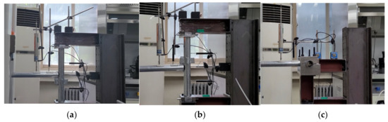
Figure 2.
Overview of the test setup: (a) DN-1; (b) UP-1; (c) LAT-1.
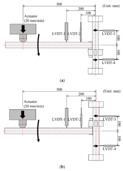
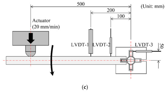
Figure 3.
Test configuration and measure points: (a) DN-1~30 [17]; (b) UP-1~30; (c) LAT-1~30.
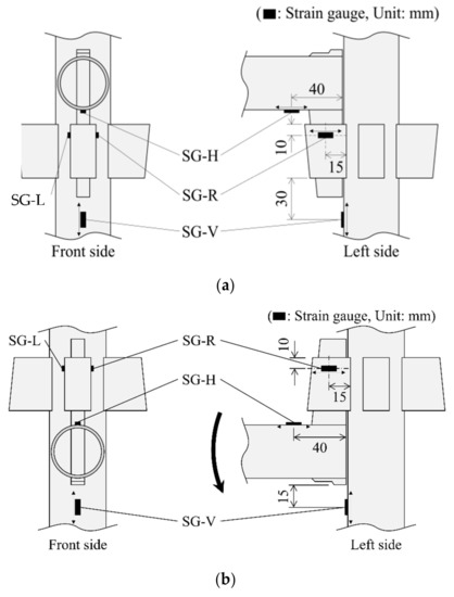
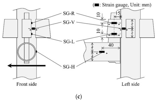
Figure 4.
Test configuration and measurement points: (a) DN-1; (b) UP-1; (c) LAT-1.
4. Results
4.1. Failure Shape
The failure shapes of the specimens were analyzed according to the connections’ rotation directions. Figure 5, Figure 6 and Figure 7 show the failure shapes of the specimens that were subjected to downward rotation, upward rotation, and lateral rotation, respectively. In the case of the downward rotation specimens (Figure 5), the main deformation occurred in the pin and the pocket, which have lower yield strength than the steel pipe, and yielding occurred at the top of the part where the pin and the pocket make contact (Figure 5b,c) in the connection’s structural shape. In addition, slight deformation occurred in the part of the horizontal member steel pipe that made contact with the bottom part of the pin.
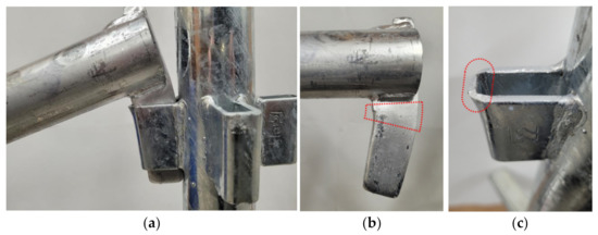
Figure 5.
Deformation shapes after test of downward rotation: (a) wholeness; (b) pin; (c) vertical pipe.
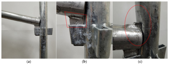
Figure 6.
Deformation shapes after test of upward rotation: (a) wholeness; (b) pin; (c) vertical pipe.
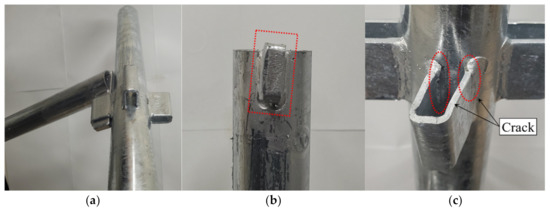
Figure 7.
Deformation shapes after test of lateral rotation: (a) wholeness; (b) pin; (c) pocket.
In the upward rotation specimens (Figure 6), bending occurred in the neck part of the pin as in the case of the downward rotation specimens, but there was a difference in the deformation of the pocket. When the connection was rotated downward, deformation or failure occurred in a section of the top part of the pocket (the top of the surface that makes contact with the pin and is subjected to direct force) owing to bending in the pin; however, in the case of upward rotation, there was negligible deformation of the pocket, and the surface of the vertical steel pipe was caved in where the vertical pipe was in contact with the end of the horizontal pipe. As the load increased, the vertical steel pipe gradually started to bend at a contact section with the end of the horizontal steel pipe (Figure 6c). Thus, the pin moved upward and rotated due to the deformation of the contact. The moment-resistant capacity of the connection can be derived from the resistance of the contact surface. In the case of lateral rotation (Figure 7), the failure shape was quite different than that of upward and downward rotation, and a very small amount of torsional deformation occurred in the pin. The connection pockets of the lateral rotation specimens were deformed in the direction of the rotation, and cracks occurred in the bent part of the pocket in some specimens. The connection deformation results caused by rotation in each direction show that different stress conditions occurred according to the rotation direction in the pocket-type connections, which have a vertically asymmetrical shape.
4.2. Load-Displacement Curve and Stress-Rotation Curve
Figure 8, Figure 9 and Figure 10 show load–displacement curves of the connection specimens according to the load direction. As shown in the figures, the upward-direction specimens had the greatest load-displacement capacity, followed by the downward-direction specimens. The lateral-direction specimens were found to resist a low level of moment. For the downward rotation specimens (Figure 8), initial sliding occurred in some specimens due to the slip in the contact section between the pin and the vertical steel pipe. However, there is no problem in calculating the moment-rotation curve since the position of the rotational axis, which is the intersection point of the horizontal pipe’s central axis and the vertical pipe’s central axis, remained almost unchanged. The yield of the specimen occurred at the pocket in contact with the pin. Since the yield strength of the pocket was the smallest compared with other parts, the yield strength of the pin seems to have dominated the yield strength of the specimen. The yield of specimens occurred at a load range of 1.22 kN–1.91 kN (Average = 1.39 kN, S.D. = 0.06 kN), where the top part of the pocket started to yield. As the load increased, the top part of the pocket was bent and reached its ultimate state, as shown in Figure 5. The maximum loads were in the range of 1.64 kN–2.00 kN (Average = 1.87 kN, S.D. = 0.08 kN).
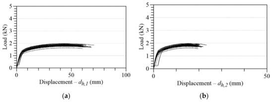
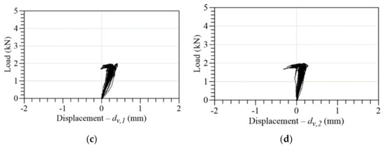
Figure 8.
Load–displacement curves of downward rotation: (a) LVDT-1; (b) LVDT-2; (c) LVDT-3: (d) LVDT-4.
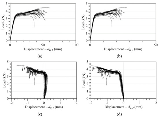
Figure 9.
Load–displacement curves of upward rotation: (a) LVDT-1; (b) LVDT-2; (c) LVDT-3: (d) LVDT-4.
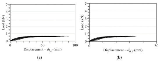
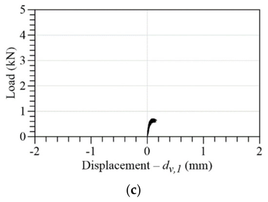
Figure 10.
Load–displacement curves of lateral rotation: (a) LVDT-1; (b) LVDT-2; (c) LVDT-3.
The results of the upward rotation specimens are shown in Figure 9. Unlike the results of downward rotation specimens, the structural behavior of the upward rotation specimen was dominated by the contact section between the vertical steel pipe and the end of the horizontal pipe, as explained in the deformation shape. When the vertical steel pipe yielded, the connection specimen began to yield. The yield load range was 2.95 kN–3.53 kN (Average = 3.28 kN, S.D. = 0.12 kN). As the load increased, the vertical steel pipe gradually bent inward. When the vertical steel pipe reached its ultimate state, the maximum load occurred. The maximum load range was 3.61 kN–4.50 kN (Average = 3.95 kN, S.D. = 0.25 kN). The width of the initial straight line before yielding was relatively smaller than that of the downward specimens due to the contact resistance resulting from the surface of the vertical steel pipe. The horizontal displacements of the top and bottom of the vertical steel pipe around the connection point initially indicated different directions, while those of the downward rotation specimens showed the same direction. It means that the pocket-type connection resists upward rotation more strongly. The specimens with the upward rotation have the largest load-displacement capacity.
For the specimens with lateral rotation, the smallest load-displacement capacity is shown in Figure 10. The range of initial stiffness was very wide, and the yield of specimens occurred at a load range of 0.13 kN–0.58 kN (Average = 0.46 kN, S.D. = 0.09 kN). As the load increased, the connection pocket of the lateral rotation specimens deformed in the direction of the rotation, and cracks occurred in welded part. Thus, the specimen began to yield in the low load, and the resistance capacity was dominated by the rotational stiffness of the pocket and the welded part. The maximum loads were in the range of 0.59 kN–0.72 kN (Average = 0.66 kN, S.D. = 0.04 kN). The difference between yield load and maximum load is relatively small.
The stress-strain curves are investigated to analyze the behavior caused by the rotation of the pocket-type connections. Figure 11 shows stress-rotation curves that were converted from strain rates according to the rotation angles of the connections in the first and second specimens for each rotation direction, as measured by strain gauges attached to the steel pipes and pockets.
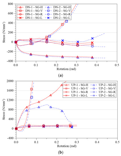
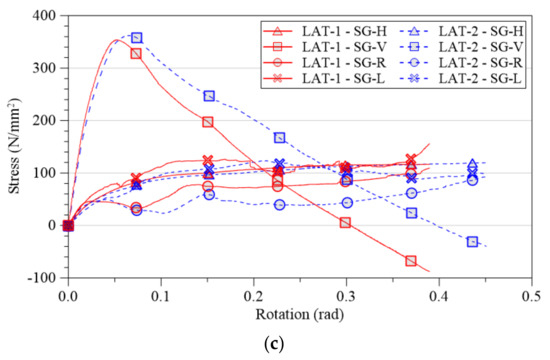
Figure 11.
Stress–rotation curves according to the rotation direction: (a) downward rotation; (b) upward rotation; (c) lateral rotation.
In the case of the downward rotation (Figure 11a), continuous compressive stress occurred after applying a load at the point of the strain gauge (SG-V) attached to the horizontal member steel pipe. The maximum compressive stress at the location where the strain gauge was attached to the horizontal member steel pipe (DN-1–SG-H: 316.7 MPa, DN-2–SG-H: 335.8 Mpa) was less than 50% of the yield strength of the horizontal member steel pipe material (698.0 Mpa). In the case of the measurement point where the strain gauge (SG-H) was attached to the vertical member steel pipe, compressive stress occurred in the initial rotation part, but after the maximum compressive stress, the stress reversed and became tension. The tensile stress that occurred afterward increased continuously and attained a yield strength (639.0 Mpa) around the point where the connection’s maximum moment was reached. It was found that plastic deformation occurred in the steel pipe as the lower part of the pin pressed on the vertical member steel pipe due to the rotation of the connection, but it was determined to be a minor degree of deformation compared to the deformation of the pin when the shape of the connection was examined after the end of the experiments (Figure 8). The stress that occurred at the strain gauges attached to both sides of the top part of the pocket (SG-R, L) was smaller than the stress that occurred in the steel pipe, and the difference in the stress that occurred on the left side and the right side was small in both the DN-1 and DN-2 specimens.
Tensile stress occurred at the initial rotation angle, and after around 0.1–0.2 rad, it reversed and became compressive stress. It was determined that the pocket was under tension owing to the pin at the beginning of the experiments, and the stress at the SG-R and L stress measurement locations at the left and right top part of the pocket began to decrease as tearing occurred at the top of the front part of the pocket. In addition, the compressive stress that occurred in the latter part of the experiments was determined to be affected by the tensile stress that occurred owing to the hammering performed after the pin was inserted in the pocket and before the strain gauges were attached. Based on the deformation shapes of the pocket-type connections and the level of stress that occurred, it was found that the main deformation in the connections of the downward rotation specimen occurred in a part of the top of the pocket (the top of the face that makes contact with the pin and which is subjected to direct force) and the pin. The section in which the rotational stiffness rapidly decreased was the rotation section where the pin and pocket began to yield, and it was found that the yielding of the pin and the pocket had the primary influence on distinguishing the pocket-type connection’s initial rotational stiffness and post-yield rotational stiffness.
As shown in Figure 11b, the horizontal steel pipe adjacent to the pin was subjected to stronger tensile stress than other locations during the initial stage of upward rotation. After a rotation angle of around 0.03 rad, the vertical steel pipe subjected to compressive stress caved in, and tensile force was generated. As this occurred, the rate of increase in the horizontal steel pipe’s tensile stress decreased. At this time, the stress in the pocket part was within around 70% of the yield strength (211.7 N/mm2). There is a difference between horizontal steel pipe tensile stress (UP-1-SG-H and UP-2-SG-H) under the same experimental conditions. The reason for the decrease in UP-2-SG-H after 0.15 radians is due to the occurrence of cracks in the welded part between the pin and the horizontal steel pipe of UP-2. The tensile force transmitted to UP-2-SG-H decreased due to the occurrence of cracks in the welded joint. However, in the specimen of UP-1, the crack did not occur. Since the specimen with the upward rotation has a relatively strong rotation-resistant capacity, the connection welding of the pin and the horizontal steel pipe can be broken in some specimens. It can be seen that the stiffness of the upwardly rotated connection was influenced more by the material of the vertical steel pipe than the pocket, which is a direct component of the connection. The stress in the laterally rotated connection (Figure 11c) was less than each material’s yield strength at all locations where stress was measured. Based on the pockets’ deformation shapes and the generated stress results, it appears that the stiffness of the laterally rotated connection was determined by plastic deformation or cracks that occurred in welded and bent part of the pocket.
4.3. Moment-Rotation Curve
To find the moment–rotation curves of the pocket connections, moment () was calculated using Equation (1). The rotation angles (, rad) of the downwardly rotated specimens and the upwardly rotated specimens were calculated from Equation (2), and the rotation angles of the laterally rotated specimens were calculated using Equation (3). To avoid reflecting the error that occurs owing to the bending of the horizontal member when calculating the connections’ rotation angles, the actuator’s displacement data were not considered in the calculations. Diagrams of each symbol are shown in Figure 12.
where is the load; is the distance from the vertical steel pipe’s central axis to the load point; are the displacement measurements from each displacement gauge; and are the distances from the steel pipe’s central axis to each displacement gauge.
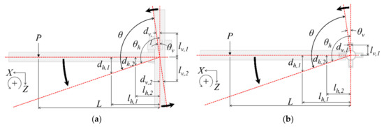
Figure 12.
Symbol designation for rotation calculation: (a) downward and upward rotation; (b) lateral rotation.
Figure 13 shows the moment–rotation relationships calculated for all specimens, and Table 4 shows the means and standard deviations of the maximum moment for each connection rotation direction. In the literature, connections are classified as rigid, semi-rigid, and nominally pin according to their rotational stiffness. These classifications correspond to the three regions divided by the dotted lines in the moment–rotation curve graph in Figure 13. The dotted lines are defined according to Eurocode 3 [19]. The specimens’ moment–rotation curves each show differences according to the rotation direction. The specimens that showed the maximum moment were the upwardly rotated specimens, and the mean was 1.942 kNm. In the case of upward rotation, the moment–rotation curves rapidly decreased after the maximum moment occurred (approximately 0.19–0.27 rad). It seems that the rotational stiffness, which corresponds to the slope of the moment–rotation curve, rapidly decreased at around 0.03 rad before the maximum moment occurred. The rotation angle of 0.03 rad indicates the time at which denting occurred in the vertical steel pipe, and the vertical steel pipe significantly affected the rotational stiffness of the upwardly rotated connection. There was no noticeable deformation of the pocket during the loading of upward rotation. When the contact section of the vertical steel pipe with the end of the horizontal steel pipe yielded, the moment-rotation curve showed the yielding. The maximum capacity was derived from the ultimate capacity of vertical steel pipe in local bending.
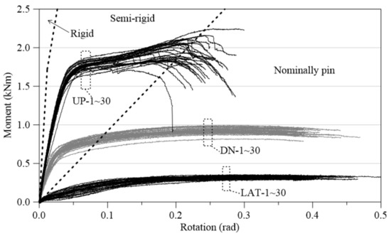
Figure 13.
Moment–rotation curves divided according to the rotation direction, with references to Eurocode 3.
Table 4.
Maximum moments of specimens for each rotation direction.
On the other hand, in downward rotation, which resists rotation relying on the low strength of pins and pockets without interference in the vertical pipe, the rotational stiffness decreased at small angles (about 0.01 rad) compared to upward rotation, and gradual deformation occurred in the upper part of the pocket after about 0.01 rad. When the top part of the pocket in contact with the pin started to yield, the moment-rotation curves showed the yielding state. As the load increased, the moment gradually increased, affecting the pocket capacity, and the mean maximum load was 0.934 kN.
The lateral rotation case showed the smallest moment capacity with a mean moment of 0.321 kNm, and it had a moment–rotation curve that was gradual overall. The rotation angle in the yield state was the biggest among the specimens. In the rotation range of about 0.05 rad to 0.10 rad, the pocket that maintained a rectangular cross-section was changed to a parallelogram due to the yield of the pocket bend. As the load increased, the pocket was gradually distorted, and the crack propagated in the welded part. Thus, the specimen with the lateral rotation represented the smallest moment capacity. In comparing the mean values of the maximum moment according to the rotation direction, it was found that the maximum moment of the upward rotation increased to 2.08 times that of the downward rotation, but the maximum moment of the lateral rotation decreased significantly to 0.34 times that of the downward rotation.
In the connection classifications of Eurocode 3 [19], if the connection’s stiffness belongs in the nominally pin connection or rigid connection regions, the connection can be a nominally pin or rigid connection during the design. In the case of the lateral rotation in Figure 13, the connection can be considered a hinge; however, the initial rotational stiffness of the rotation directions other than lateral rotation was such that they are both located in the semi-rigid region. These results mean that it will be difficult to accurately predict the overall safety of system scaffolding if its connections are assumed to be hinges when a structural analysis is performed on a system scaffolding structure. Therefore, to perform an accurate structural analysis on scaffolding structures with pocket-type connections, the connections should be treated as semi-rigid connections when defining the stiffness of the connections’ upward and downward rotations. In addition, there are differences in the moment–rotation curves and maximum rotation according to the rotation direction; therefore, individual rotation stiffness models should be used for each rotation direction. On the other hand, depending on the designer’s engineering judgment, it may be possible to consider the connection as a hinge instead of a stiffness model in the case of horizontal rotation.
4.4. Rotational Stiffness of Connections
Scaffolding design typically focuses on providing adequate structural integrity, stability, and load-carrying capacity while adhering to recognized industry standards, codes, and regulations. In the case of general scaffolding design, there is no need to consider the yield deformation capacity of connections where the connections are assumed to be hinges. However, in the case of investigating the accurate ultimate behavior of the scaffolding and identifying vulnerable components under various loads, it is necessary to consider the plastic deformation capacity of connections. The moment–rotation curves of the pocket-type connections do not show any initial rotation angle looseness [13] owing to the shape of the connections and the method of tightening by hammering the members, etc. Therefore, in this study, the rotational stiffness models for the pocket-type connections were assumed to have a bilinear form similar to the actual moment–rotation curves. Figure 14 defines the rotational stiffness values (, ) and reference rotation angles (, ) that are parameters of the assumed bilinear rotational stiffness model. If the simple mean of the values of each specimen’s bilinear rotational stiffness model are used as the mean value of , which is the reference for changing rotational stiffness, the continuity of each rotational stiffness cannot be guaranteed. Therefore, as shown in Equation (4), the mean of was calculated as a weighted mean using the initial rotational stiffness () as a weight value.

Figure 14.
Bilinear rotational stiffness model.
Figure 15 and Table 5 show the major parameters of the bilinear rotational stiffness model for each rotation direction of the pocket-type connections, which were derived from the results of experiments in this study and the authors’ previous study [17]. Research has been conducted on the reliability analysis of scaffolding structures [20,21,22]. In order to provide statistical characteristics of random variables for the rotation stiffness that can be used in the reliability analysis of scaffolding structures, the derived bilinear rotational stiffness model for pocket-type connections also includes the rotational stiffness’ (, ) coefficient of variation and 5th and 95th percentiles, along with the mean values of the parameters. In the rotational stiffness model of the downwardly rotated connections, the mean of the initial rotational stiffness (, rotation range: 0.000–0.025 rad) was 28.378 kNm/rad, and the mean of the post-yield rotational stiffness (second rotational stiffness, , rotation range: 0.025–0.196 rad) was 1.450 kNm/rad. In the rotational stiffness model of the upwardly rotated connections, the mean of the initial rotational stiffness (, rotation range: 0.000–0.035 rad) was 47.138 kNm/rad, and the mean of the second rotational stiffness (, rotation range: 0.035–0.169 rad) was 2.461 kNm/rad. In the rotational stiffness model of the laterally rotated connections, the mean of the initial rotational stiffness (, rotation range: 0.000–0.073 rad) was 3.144 kNm/rad, and the mean of the second rotational stiffness (, rotation range: 0.073–0.197 rad) was 0.577 kNm/rad. However, the coefficient of variation of the initial rotational stiffness of the laterally rotated connections was very large compared to the other rotational stiffness values, indicating some uncertainty. However, it can be considered a nominally pin connection when performing analyses according to Eurocode 3 [19].
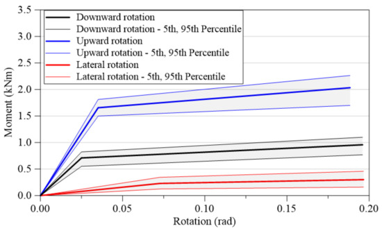
Figure 15.
Bilinear rotational stiffness model of pocket-type connection divided according to the rotation direction.
Table 5.
Parameters of bilinear rotational stiffness model.
The derived rotational stiffness model shows the need for the analysis of the rotational stiffness of pocket-type connections in different rotation directions other than downward rotation, which is the rotation direction that is generally considered in the existing literature pertaining to the rotational stiffness of connections in temporary equipment. Using the downward rotational stiffness of pocket-type connections as a reference, the initial rotational stiffness of upward rotation () was 1.66 times that of downward rotation, and the second rotational stiffness () was 1.70 times that of the downward rotation. In the case of lateral rotation, the initial rotational stiffness was 0.11 times that of the downward rotation, and the second rotational stiffness was 0.4 times that of the downward rotation. As such, it was found that there was a large decrease in the rotational stiffness. Therefore, the rotational stiffness of pocket-type connections is proposed as a bilinear model in which the initial stiffness and the second stiffness vary according to the rotation direction (downward rotation, upward rotation, or lateral rotation).
5. Conclusions
This study performed experiments to evaluate the rotational stiffness that can occur in the horizontal members of pocket-type connections. Upward rotation and lateral rotation experiments were performed on 30 specimens each, and the results of the authors’ previous downward rotation experiments were used to analyze the failure shapes and moment–rotation curves of the specimens as well as to make the following conclusions.
- (1)
- There were differences in the failure shapes of pocket-type connections according to the rotation direction. In the case of the downwardly rotated specimens, the main failure shape occurred in the pins and pockets, which have low yield strength, rather than the steel pipes. In the upwardly rotated specimens, deformation or failure occurred in some of the top parts of the pocket owing to the bending of the pin; however, the deformation of the pocket was negligible, and cave-in phenomena occurred in the part of the vertical steel pipe that made contact with the end of the horizontal steel pipe. In the laterally rotated specimens, there was little torsional deformation of the pins, but there was deformation in the rotation direction of the pocket, and in some of the specimens, cracks occurred in the bent part of the pocket. Owing to the differences in the failure phenomena, the maximum moment capacity of the upwardly rotated specimens was the largest, followed by that of the downwardly rotated specimens and the laterally rotated specimens in that order.
- (2)
- A bilinear rotational stiffness model is appropriate for the moment–rotation curves that result from each rotation direction of the pocket-type connections. Based on the moment–rotation curves, it was determined that the connections correspond to semi-rigid connections in the Eurocode 3 connection classification system when the rotation direction is downward or upward, and they can be considered nominally pin connections during structural analysis when the rotation direction is lateral.
- (3)
- Considering the rotational stiffness during the upward rotation of the pocket-type connections, the initial stiffness () was found to be 47.138 kNm/rad, and the second stiffness () was found to be 2.461 kNm/rad, while the initial stiffness of the downward rotation was 28.378 kNm/rad, and the second stiffness was 1.450 kNm/rad. In contrast, the initial stiffness of lateral rotation was 3.144 kNm/rad, and the second stiffness was 0.577 kNm/rad. A bilinear model can be proposed in which the initial and second rotational stiffness values of upward rotation are, respectively, 1.66 and 1.70 times that of the downward rotation, and the initial and second rotational stiffness values of lateral rotation are respectively 0.11 times and 0.4 times that of the downward rotation.
Author Contributions
Conceptualization, D.-H.C. and J.-H.W.; methodology, D.-H.C.; validation, J.-H.W.; investigation, D.-H.C. and J.-H.W.; writing—original draft preparation, D.-H.C.; writing—review and editing, J.-H.W.; visualization, D.-H.C. All authors have read and agreed to the published version of the manuscript.
Funding
This work was partially supported by the Human Resources Development of the Korea Institute of Energy Technology Evaluation and Planning (KETEP) grant funded by the Korean government Ministry of Knowledge Economy (No. 20224000000070, Human Resource Training for Smart Energy New Industry Cluster).
Institutional Review Board Statement
Not applicable.
Informed Consent Statement
Not applicable.
Data Availability Statement
Data that support the findings of this study are available from the corresponding author upon reasonable request.
Conflicts of Interest
The authors declare no conflict of interest.
References
- Park, M.S.; Choi, B.J.; Han, M.H.; Lim, H.T.; Cho, T.G. A study on the improvements of assembling methods of system support for enhancing economic safety. J. Disaster Saf. 2017, 1, 9–18. (In Korean) [Google Scholar]
- Bong, J.K.; Lee, H.D.; Kim, S.; Mha, H.S.; Yim, D.K.; Won, J.H. Probabilistic characteristics of moment capacity and rotational stiffness of wedge joints used in support systems reflecting reused members. Appl. Sci. 2019, 9, 4056. [Google Scholar] [CrossRef]
- Holam, A.; Sawicki, M.; Szóstak, M. Occupational accidents involving construction scaffolding using Pareto-Lorenz analysis. Appl. Sci. 2018, 8, 48. [Google Scholar] [CrossRef]
- López Arquillos, A.; Rubio Romero, J.; Gibb, A. Analysis of construction accidents in Spain, 2003–2008. J. Saf. Res. 2012, 43, 381–388. [Google Scholar] [CrossRef] [PubMed]
- Peng, J.L.; Yen, T.; Kuo, C.C.; Chan, S.L. Analytical and experimental bearing capacities of system scaffolds. J. Zhejiang Univ. 2009, 10, 82–92. [Google Scholar] [CrossRef]
- Błazik-Borowa, E.; Szer, J.; Borowa, A.; Robak, A.; Piénko, M. Modelling of load-displacement curves obtained from scaffold components tests. Bull. Pol. Acad. Sci. Tech. Sci. 2019, 67, 317–327. [Google Scholar]
- KDS 21 00 00: 2022; Temporary Facilities Design Standards. Ministry of Land, Infrastructure and Transport (MOLIT): Sejong City, Republic of Korea, 2022. (In Korean)
- KDS 21 50 00: 2022; Formwork and Support Design Standards. Ministry of Land, Infrastructure and Transport (MOLIT): Sejong City, Republic of Korea, 2022. (In Korean)
- KDS 21 60 00: 2022; Scaffolding and Safety Facility Design Standards. Ministry of Land, Infrastructure and Transport (MOLIT): Sejong City, Republic of Korea, 2022. (In Korean)
- Godley, M.H.R.; Beale, R.G. Analysis of large proprietary access scaffold structures. Proc. Inst. Civ. Eng. Civ. Eng. 2001, 146, 31–39. [Google Scholar] [CrossRef]
- Peng, J.L.; Wu, C.W.; Chan, S.L.; Huang, C.H. Experimental and numerical studies of practical system scaffolds. J. Constr. Steel Res. 2013, 91, 64–75. [Google Scholar] [CrossRef]
- Jia, L.; Liu, H.; Chen, Z.; Liu, Q.; Wen, S. Mechanical properties of right-angle couplers in steel tube—Coupler scaffolds. J. Constr. Steel. Res. 2016, 125, 43–60. [Google Scholar] [CrossRef]
- Chandrangsu, T.; Rasmussen, K.J.R. Investigation of geometric imperfections and joint stiffness of support scaffold systems. J. Constr. Steel. Res. 2011, 67, 576–584. [Google Scholar] [CrossRef]
- Pieńko, M.; Błazik-Borowa, E. Experimental studies of ringlock scaffolding joint. J. Constr. Steel. Res. 2020, 173, 106265. [Google Scholar] [CrossRef]
- Won, J.H.; Lee, H.D.; Choi, M.K.; Park, M.C. Flexural strength and rotational stiffness estimation of joint between vertical and horizontal members in system support. J. Korean Soc. Saf. 2018, 33, 46–53. (In Korean) [Google Scholar]
- Zheng, Y.F.; Guo, Z.X. Investigation of joint behavior of disk-lock and cuplok steel tubular scaffold. J. Constr. Steel. Res. 2021, 177, 106415. [Google Scholar] [CrossRef]
- Chung, D.H.; Jang, N.G.; Won, J.H. An experimental study on the rotational stiffness of system scaffolding with pocket type connection. J. Korean Soc. Steel. Const. 2023, 35, 11–19. (In Korean) [Google Scholar] [CrossRef]
- Notice of Safety Certification for Protective Devices. Available online: https://www.law.go.kr/LSW//admRulLsInfoP.do?admRulSeq=2100000199056 (accessed on 24 March 2023). (In Korean).
- EN 1993-1-8: 2005; Eurocode 3: Design of Steel Structures. Part 1.8: Design of Joints. European Committee for Standardization (CEN): Brussels, Belgium, 2005.
- Zhang, H.; Chandrangsu, T.; Rasmussen, K.J.R. Probabilistic study of the strength of steel scaffold systems. Struct. Saf. 2010, 32, 393–401. [Google Scholar] [CrossRef]
- Zhang, H.; Rasmussen, K.J.R.; Ellingwood, B.R. Reliability assessment of steel scaffold shoring structures for concrete formwork. Eng. Struct. 2012, 36, 81–89. [Google Scholar] [CrossRef]
- Wang, C.; Zhang, H.; Rasmussen, K.J.R.; Reynolds, J.; Yan, S. System reliability-based limit state design of support scaffolding systems. Eng. Struct. 2020, 216, 110677. [Google Scholar] [CrossRef]


Disclaimer/Publisher’s Note: The statements, opinions and data contained in all publications are solely those of the individual author(s) and contributor(s) and not of MDPI and/or the editor(s). MDPI and/or the editor(s) disclaim responsibility for any injury to people or property resulting from any ideas, methods, instructions or products referred to in the content. |
© 2023 by the authors. Licensee MDPI, Basel, Switzerland. This article is an open access article distributed under the terms and conditions of the Creative Commons Attribution (CC BY) license (https://creativecommons.org/licenses/by/4.0/).